

Page 1

Getting Started with the
MapleSim Connector
Copyright © Maplesoft, a division of Waterloo Maple Inc
Maplesoft, a division of Waterloo Maple Inc
Page 2

Getting Started with the MapleSim Connector
Copyright
Maplesoft, Maple, and MapleSim are all trademarks of Waterloo Maple Inc.
© Maplesoft, a division of Waterloo Maple Inc. 1996-2009. All rights reserved. No part of this book may be reproduced, stored in a retrieval system, or transcribed, in any form or by any means — electronic, mechanical,
photocopying, recording, or otherwise. Information in this document is subject to change without notice and does
not represent a commitment on the part of the vendor. The software described in this document is furnished under
a license agreement and may be used or copied only in accordance with the agreement. It is against the law to
copy the software on any medium except as specifically allowed in the agreement.
Macintosh is a trademark of Apple Inc., registered in the U.S. and other countries.
MATLAB and Simulink are registered trademarks of The MathWorks, Inc.
All other trademarks are the property of their respective owners.
This document was produced using a special version of Maple and DocBook.
Printed in Canada
Page 3

Contents
Introduction ................................................................................................... v
1 Getting Started ............................................................................................. 1
1.1 Setting Up the MapleSim Connector ........................................................... 1
Establishing a Connection with MATLAB .................................................... 1
1.2 Getting Help .......................................................................................... 1
1.3 Using the Simulink Block Generation Template ............................................ 2
Viewing MapleSim Connector Examples ..................................................... 2
1.4 Example: RLC Circuit Model ................................................................... 3
1.5 Preparing a Model for Export .................................................................... 5
Converting the Model to a Subsystem .......................................................... 6
Defining Subsystem Inputs and Outputs ...................................................... 7
Define and Assign Subsystem Parameters . .. .. .. .. .. .. .. .. .. .. .. .. .. .. .. .. .. .. .. .. .. .. .. .. .. 11
Exporting Your Model Using the Simulink Block Generation Template ............ 13
Implement the S-Function Block in Simulink .. .. .. .. .. .. .. .. .. .. .. .. .. .. .. .. .. .. .. .. .. .. .. 15
2 Creating and Exporting Mathematical Models in Maple ..................................... 17
2.1 Using a Template to Generate an S-Function Block ..................................... 17
2.2 Creating and Exporting a DynamicSystems Object Programmatically ............. 19
2.3 Example: DC Motor .............................................................................. 20
Index ........................................................................................................... 23
iii
Page 4

iv • Contents
Page 5

Introduction
The MapleSim™ Connector provides all of the tools you need to prepare and export your
dynamic systems models to Simulink® as S-function blocks. You can create a model in
MapleSim, simplify it in Maple™ by using an extensive range of analytical tools, and then
generate an S-function block that you can incorporate into your Simulink toolchain.
You can also use these tools for exporting mathematical models that you have created from
first principles in Maple as S-functions.
Furthermore, various options allow you to use the C code generation feature in Maple to
create code libraries of your MapleSim models for implementation in other applications.
Features of this toolbox include:
• Maple templates, which provide an intuitive user interface for optimizing your
MapleSim model, and then generate an S-function in Simulink.
• A range of examples illustrating how to prepare and export your models.
• A direct interface between Maple and Simulink allows you to generate and test an Sfunction block as you develop the model.
• Commands for developing S-functions of mathematical models from first principles in
the Maple environment and examples to illustrate how to do it.
• Access to commands in the SimulinkConnector and DynamicSystems packages for
developing automated applications to generate S-functions.
Scope of Model Support
MapleSim is a very comprehensive modeling tool where it is possible to create models that
could go beyond the scope of this MapleSim Connector release. In general, the MapleSim
Connector supports systems of any complexity, including systems of DAEs of any index,
in any mix of domains, as long as they exhibit continuous behavior. Systems that contain
any type of discontinuity, including discrete transforms, switches, logic gates, relational
and Boolean operations are not supported by the current release of this product.
Apart from all of the engineering and signal components that are continuous, this product
also supports lookup tables, and custom components that do not use discontinuous operations
such as piecewise functions.
v
Page 6

vi • Introduction
System Requirements
The MapleSim Connector requires the following:
• MATLAB® 2008b, 2009a or 2009b
• Simulink 7.0 or later
• The latest versions of Maple and MapleSim
For installation instructions and a complete list of system requirements, see the Install.html
file on the product CD.
Page 7
1 Getting Started
1.1 Setting Up the MapleSim Connector
Establishing a Connection with MATLAB
To generate an S-function block, you must set up Maple to communicate with MATLAB.
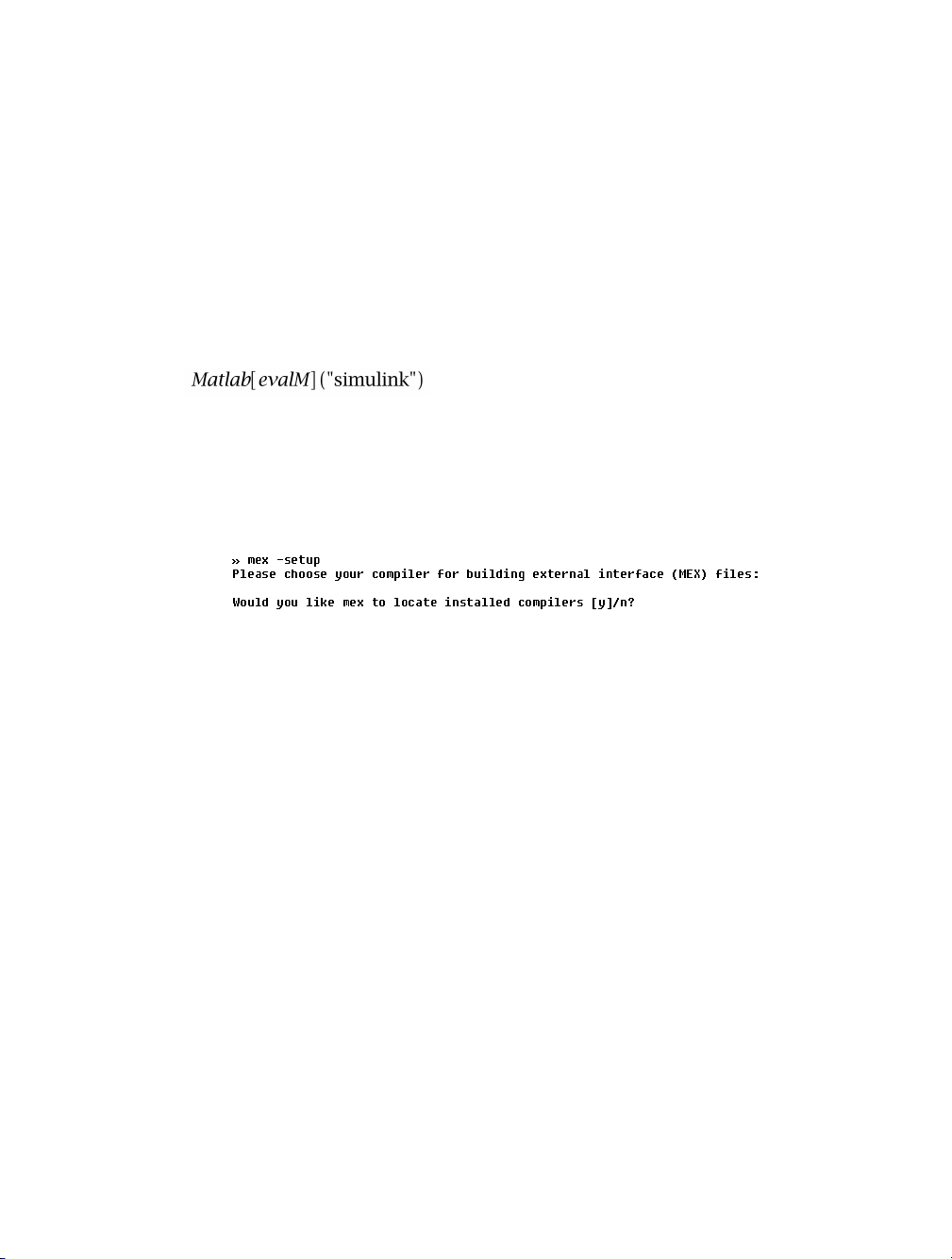
Start Maple and enter the following command to establish a connection with MATLAB.
>
A MATLAB command window is opened and the connection is established. If the window
does not open, follow the instructions in the ?Matlab[setup] help page to configure the
connection.
Next, set up the MATLAB mex compiler. Go to the MATLAB command window and enter
the setup command.
Follow the instructions to choose a local C compiler that supports ANSI (American National
Standards Institute) C code.
See the ?SimulinkConnector,setup help page for more information.
You are now ready to use the MapleSim Connector.
1.2 Getting Help
In Maple, enter ?SimulinkConnector at a prompt in a worksheet.
1
Page 8
2 • 1 Getting Started
1.3 Using the Simulink Block Generation Template
The MapleSim Connector provides a Simulink Block Generation template in the form of
a Maple worksheet for manipulating and exporting MapleSim subsystems. This template
contains pre-built embedded components that allow you to generate S-function or C code
from a MapleSim subsystem, export the subsystem as a Simulink block, and save the source
code.
Using this template, you can define inputs and outputs for the system, choose the format of
the resulting S-function, and generate the source code, library code, block script, or Simulink
block. You can also assign the model equations to a variable and use any Maple commands
to perform analysis tasks.
Viewing MapleSim Connector Examples
Toolbox examples are available in the Simulink Connector Examples palette in MapleSim.
Each example includes a code generation template in its document folder.
To view an example:
1. In the Simulink Connector Examples palette at the left side of the MapleSim window,
expand one of the submenus, and then click the entry for the model that you want to view.
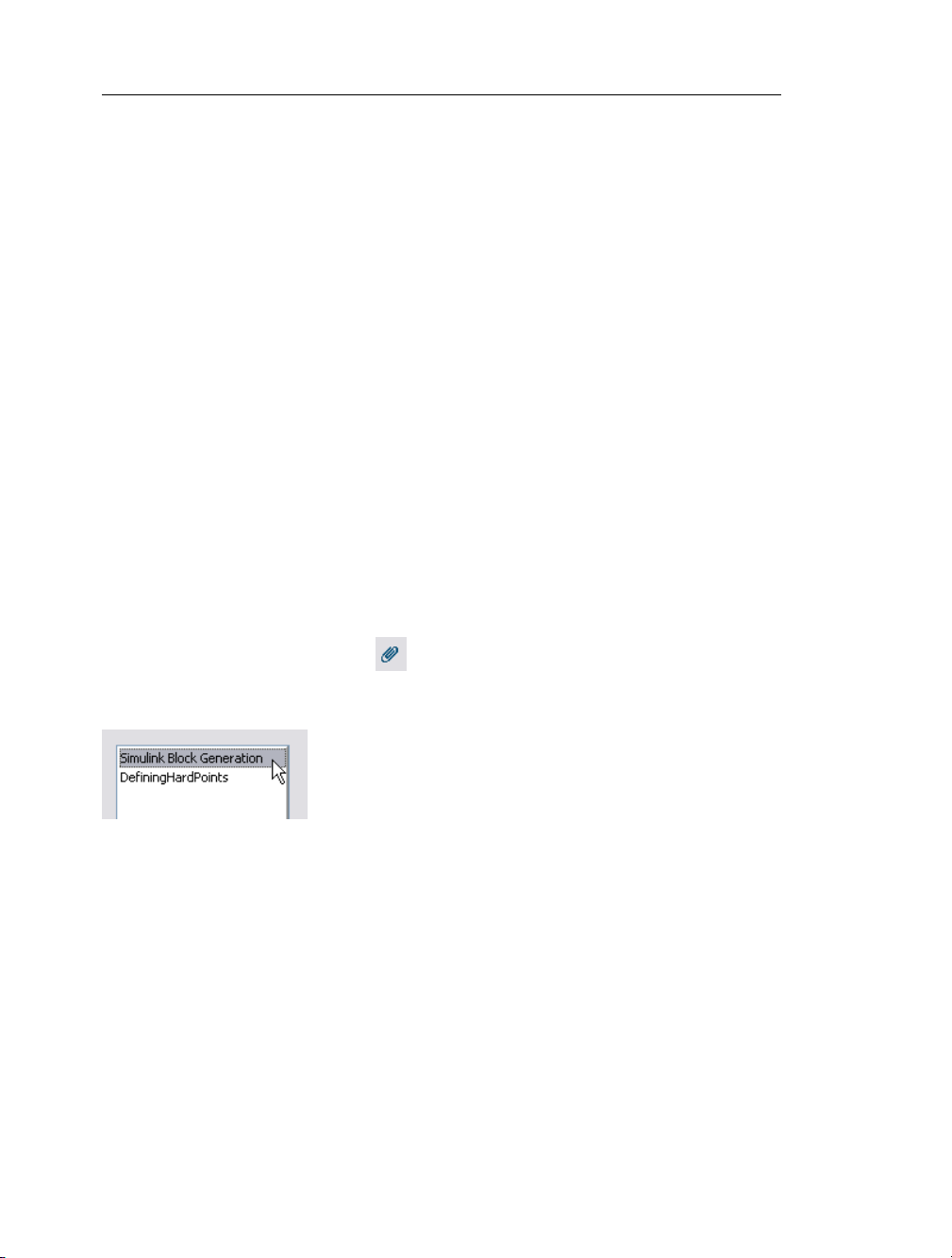
2. Click the document folder button in the top toolbar.
3. From the document list, select Simulink Block Generation.
4. Click Open Selected. The code generation template is opened in Maple.
Some models include additional documents, such as templates that display model equations
or define custom components. You can open any of these documents by selecting its entry
in the list and clicking Open Selected.
Page 9

1.4 Example: RLC Circuit Model • 3
1.4 Example: RLC Circuit Model
In this example, you will generate a Simulink block from an RLC circuit model that was
created in MapleSim.
Before starting this tutorial, you must set up MATLAB and the mex compiler. For more
information, see Establishing a Connection with MATLAB (page 1).
To generate an S-function block:
1. In the Simulink Connector Examples palette, select the RLC Parallel Circuit example.
2. Click the document folder button in the top toolbar.
3. From the drop-down menu, select Simulink Block Generation.
4. Click New.
5. Enter RLC Circuit as the worksheet name and click OK.
6. In the document list at the left side of the dialog box, select RLC Circuit and click Open
Selected. Your MapleSim model is opened in the Simulink Block Generation for
MapleSim Template in Maple.
7. In the Model Summary section of the template, from the Subsystem drop-down menu,
select the RLC_Parallel subsystem. This list box displays all of the subsystems in your
MapleSim model.
8. Click System Update. All of the template fields are populated with information specific
to the subsystem.
9. In the S-Function block name field, enter RLC_Circuit. This is the name that will be
displayed for the block in Simulink.
Page 10
4 • 1 Getting Started
You can now specify which subsystem parameters will be kept as configurable parameters
in the generated Simulink block. In this example, the resistance parameter will be kept as
a configurable parameter.
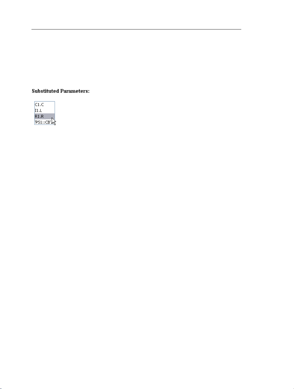
10. In the Setting Parameters section, select the R1.R parameter entry in the Substituted
Parameters list.
11. Click the > button. The entry is added to the Simulink Parameters list. The resistance
parameter will be kept as a configurable parameter in the generated Simulink block and the
parameters remaining in the Substituted Parameters list will be assigned to values during
the code generation process.
12. To change the default value of the resistance parameter, select R1.R from the Simulink
Parameters list and enter 5 in the Parameter Value field and click anywhere outside of
the field.
13. In the Advanced Code Generation Settings section, set the Code Optimization option
to Full. This option specifies the degree of simplification applied to the model equations
during the code generation process. This option eliminates redundant variables and equations
in the system.
14. In the Generate Simulink Block section, click the Model radio button.
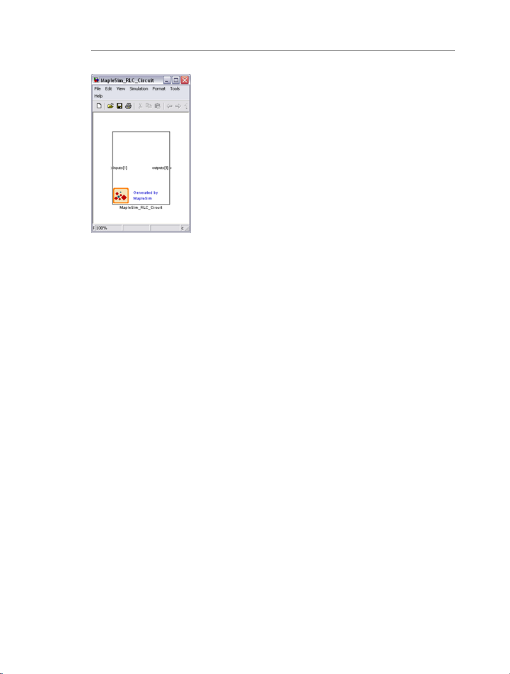
15. Click Generate to Simulink to generate the S-function code and create the block.
Note: Generating a block may require a few minutes.
A MATLAB command window is opened and the block with the specified parameters is
generated in Simulink.
Page 11
1.5 Preparing a Model for Export • 5
Double-clicking the block opens the mask that contains the symbolic parameters from the
original model. This block can now be connected with any compatible Simulink blocks.
1.5 Preparing a Model for Export
In this example, you will perform the steps required to prepare a slider-crank mechanism
model and export it as an S-function block:
1. Convert the slider-crank mechanism model to a subsystem.
2. Define subsystem inputs and outputs.
3. Define and assign subsystem parameters.
4. Export the model using the Simulink Block Generation template.
5. Implement the S-function block in Simulink.
The following tutorial will take you through these steps in detail. Before starting this tutorial,
you must set up MATLAB and the mex compiler. For more information, see Establishing
a Connection with MATLAB (page 1).
To open the slider-crank mechanism example:
1. In MapleSim, expand the Examples palette and then expand the Multibody submenu.
2. Open the Slider Crank Mechanism example.
Page 12

6 • 1 Getting Started
Converting the Model to a Subsystem
By converting your entire model or part of your model into a subsystem, you identify which
parts of the model that you want to export. In this example, you will prepare the system for
export by grouping all of the components into a subsystem.
1. Using the selection tool ( ) located above the model workspace, draw a box around all
of the components in the model.
2. From the Edit menu, select Create Subsystem.
3. In the Create Subsystem dialog box, enter SliderCrank as the subsystem name.
Page 13

1.5 Preparing a Model for Export • 7
4. Click OK. A SliderCrank subsystem block is displayed in the model workspace.
Defining Subsystem Inputs and Outputs
Simulink only supports data signals. Properties on acausal ports, such as mechanical flanges
and electrical pins, must be converted to signals using the appropriate components. The
resulting signals can then be directed as inputs and outputs for the subsystem in MapleSim
and for the S-function block.
In this example, you will convert the displacements of the slider and the joint between the
crank and connecting rod to output signals. The input signal needs to be converted to a
torque that is applied to the revolute joint that represents the crank shaft.
1. Double-click the subsystem block to view its contents. The broken line surrounding the
components indicates the subsystem boundary, which can be resized by clicking and dragging
its sizing handles.
2. Delete the probes that are attached to the model.
3. On the left side of the MapleSim window, expand the Multibody palette and then expand
the Sensors submenu.
4. Drag the Absolute Translation component to the model workspace and place it below
the Prismatic Joint component.
5. Right-click (Control-click for Macintosh®) the Absolute Translation component and
select Rotate Counterclockwise.
6. From the Signal Blocks → Routing → Demultiplexers menu, drag a 3-port Demulti-
plexer component to the model workspace and place it to the right of the Absolute Trans-
lation component.
Page 14

8 • 1 Getting Started
7. To connect the Absolute Translation component to the model, click the frame (the white
square connector). The frame is highlighted in green when you hover your pointer over it.
8. Draw a vertical line and click the connection line directly above the component. The
sensor is connected to the rest of the diagram.
9. In the same way, connect the r output port of the Absolute Translation component to
the navy blue input port of the demultiplexer. This is the displacement signal from the sensor
in x, y, and z coordinates. Since the slider only moves along the x axis, you need to output
the first coordinate as a signal.
10. Hover your pointer over the first demultiplexer port and click your mouse button once.
Page 15
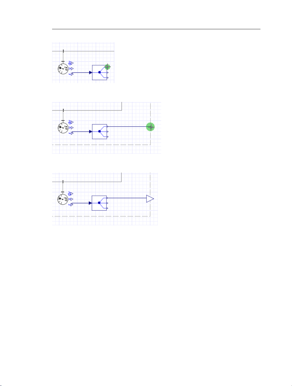
1.5 Preparing a Model for Export • 9
11. Drag your pointer to the subsystem boundary.
12. Click the boundary once. A real output port is added to your subsystem.
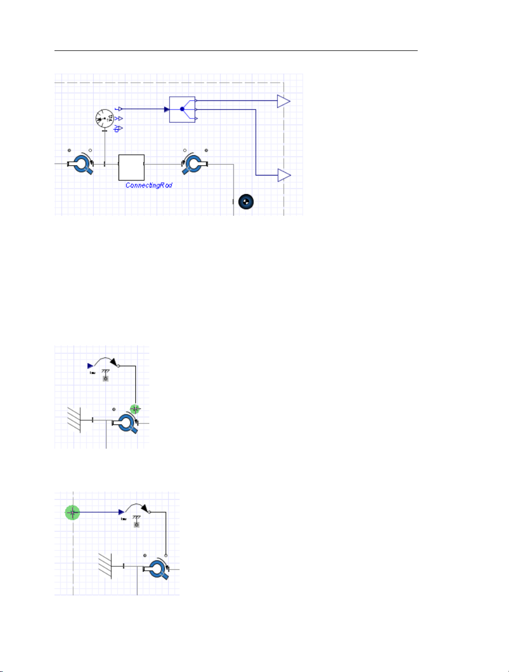
13. Add another Absolute Translation component above the Connecting Rod subsystem.
14. Right-click (Control-click for Macintosh) this Absolute Translation component and
select Flip Vertically.
15. Add a 3-port Demultiplexer component to the right of the sensor and connect the
components as shown below.
Page 16
10 • 1 Getting Started
Since the crank is moving in the x, y plane, you only need to output the first two signals.
You will now add a real input port to your subsystem to control the torque on the crank
shaft.
16. From the 1-D Mechanical → Rotational → Torque Drivers menu, add a Torque
component to the model workspace and place it above the Fixed Frame component.
17. Connect the white flange of the Torque component to the white flange of the leftmost
Revolute Joint.
18. Click the input port of the Torque component and drag your pointer to the subsystem
boundary.
Page 17
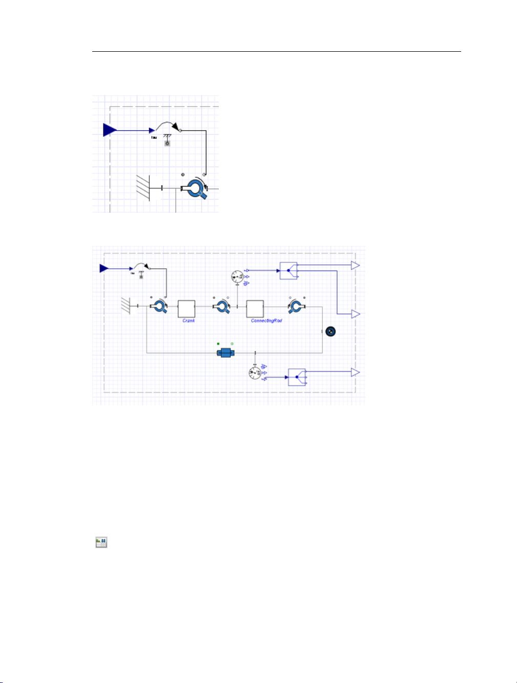
1.5 Preparing a Model for Export • 11
19. Click the boundary once. A real input port is added to your subsystem.
The complete subsystem is displayed below.
Define and Assign Subsystem Parameters
You can define custom parameters that can be used in expressions in your model to edit
values more easily. To do so, you define a parameter with a numeric value in the parameter
editor. You can then assign that parameter as a variable to the parameters of other components; those individual components will then inherit the numeric value of the parameter
defined in the parameter editor. By using this approach, you only need to change the value
in the parameter editor to change the parameter values for multiple components.
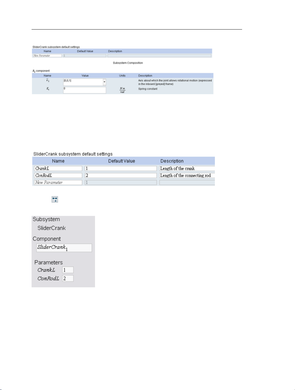
1. While in the detailed view of the SliderCrank subsystem, click the parameters button
( ) above the model workspace. The parameter editor is displayed.
Page 18
12 • 1 Getting Started
2. In the New Parameter field, define a parameter called CrankL and press Enter.
3. Specify a default value of 1 and enter Length of the crank as the description.
4. In the second row of the table, define a parameter called ConRodL and press Enter.
5. Specify a default value of 2 and enter Length of the connecting rod as the description.
6. Click to switch to the diagram view. The parameters are defined in the Parameters
pane.
7. In the model workspace, select the Crank subsystem.
8. In the Parameters pane, change the length value (L) to CrankL.
Page 19

1.5 Preparing a Model for Export • 13
The Crank subsystem now inherts the numeric value of CrankL that you defined.
9. Select the ConnectingRod subsystem and change its length value to ConRodL.
10. Click the Main button above the model workspace to navigate to the top level of the
model.
You will include these parameter values in the model that you export. You are now ready
to convert your model to an S-function block.
Exporting Your Model Using the Simulink Block Generation Template
After preparing the model, you can use the Simulink Block Generation template to set export
options and convert the model to an S-function block.
1. Click the document folder icon in the main toolbar.
2. From the drop-down menu, select Simulink Block Generation.
3. Click New.
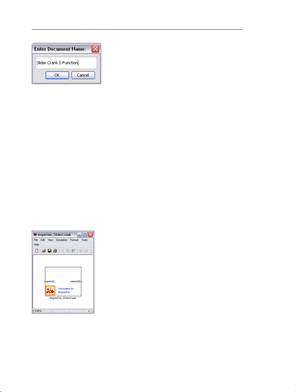
4. Enter Slider Crank S-Function as the worksheet name and click OK.
Page 20
14 • 1 Getting Started
5. In the document list at the left side of the dialog box, select Slider Crank S-Function
and click Open Selected. The slider-crank subsystem is opened in the Simulink Block
Generation for MapleSim Template in Maple.
6. From the Subsystem drop-down menu, select SliderCrank and click System Update.
All of the template fields are populated with information specific to the subsystem.
7. In the Setting Parameters section, click the >> button. The ConRodL and CrankL
parameters, which you defined in the previous section, are added to the Simulink Parameters
list. These parameters will be kept as configurable parameters in the generated Simulink
block.
8. In the Generate Simulink Block section, select the Model radio button to place the
generated block into a new Simulink model instead of the Simulink block library.
9. Click Generate to Simulink to generate the S-function code and create the block.
Note: Generating a block may require a few minutes.
A MATLAB command window is opened and the block with the specified parameters is
generated in Simulink.
Page 21
1.5 Preparing a Model for Export • 15
Implement the S-Function Block in Simulink
In Simulink, you can connect your block to other compatible blocks, specify initial conditions,
and edit the component parameter values.
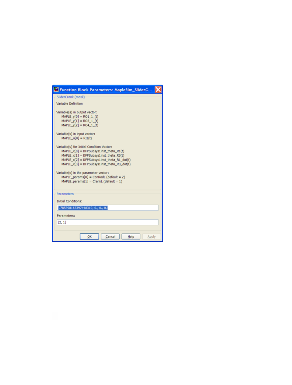
1. In Simulink, double-click the block. The Parameter Mask dialog box is displayed.
This dialog box displays the ConRodL and CrankL parameters that you defined in
MapleSim as a vector. The text in the dialog describes each parameter in the order they
appear in the vector. Initial conditions can also be changed in this dialog box.
2. Click the Help button. This window provides a model description and information about
the inputs, outputs, parameters, and initial conditions.
3. All inputs and outputs are implemented as vector signals. To access individual signals
in Simulink, use a Mux block for inputs and a Demux block for outputs.
Page 22

16 • 1 Getting Started
Page 23

2 Creating and Exporting Mathematical Models in Maple
In Maple, you can use commands from the DynamicSystems package to create a system
from first principles. Maple contains a data structure called a system object that encapsulates
the properties of a dynamic system. This data structure contains information, for example,
the description of the system, and the description of the inputs. Five different types of systems
can be created.
• Differential equation or difference equation
• Transfer function as an expression
• Transfer function as a list of numerator and denominator coefficients
• State-space
• Zero, pole, gain
You can use the Simulink Block Generation for DynamicSystems template, which provides
embedded components for generating source code and exporting a DynamicSystems object
to Simulink. To open this template, enter ?MapleSimSimulinkConnector,DynamicSys-
temsBlockGeneration at a prompt in a Maple worksheet.
Alternatively, you can create a DynamicSystems object in a new worksheet and use commands from the SimulinkConnector package to generate source code and save it as a
MATLAB .m file.
2.1 Using a Template to Generate an S-Function Block
In this tutorial, you will use the Simulink Block Generation for DynamicSystems template
to generate a Simulink block from a dynamic system defined in Maple.
Before starting this tutorial, you must set up MATLAB and the mex compiler. For more
information, see Establishing a Connection with MATLAB.
To generate an S-function block from a dynamic system:
1. In a Maple worksheet, enter ?MapleSimSimulinkConnector,DynamicSystemsBlock-
Generation. The template is opened.
2. If prompted to execute the entire worksheet, click Yes.
In the Component Equations section, you would normally define variables to store component equations and parameters.
17
Page 24

18 • 2 Creating and Exporting Mathematical Models in Maple
These variables are referenced in the equations that define the system object. For demonstration purposes, the equations and parameters of a DC Motor have been defined for you.
3. In the Generate Simulink Block section, select the Model radio button. This option
places the S-function into a new Simulink model instead of a Simulink block library.
4. Click Code Generation. The generated C code is displayed in the View Code section.
5. Click Generate to Simulink.
6. In the Select File dialog box, specify the path and name of the .m and .c files to which
to save the generated code.
7. Click Save. Maple generates the Simulink block.
Note: Generating a block may require a few minutes.
A MATLAB command window is opened and the block with the specified parameters is
generated in Simulink. Double-clicking the block opens the mask that contains the symbolic
parameters from the original model. This block can now be connected with any compatible
Simulink blocks.
Page 25

2.2 Creating and Exporting a DynamicSystems Object Programmatically • 19
2.2 Creating and Exporting a DynamicSystems Object
Programmatically
First, load the DynamicSystems and SimulinkConnector packages in the Maple worksheet.
>
>
To create a system object from the transfer function , use the following
command:
>
(2.1)
To view the details of the system, use the PrintSystem command.
>
(2.2)
The default values for the input names ( and output names have been used.
Alternatively, during creation of the system, different input and output names can be specified.
Page 26
20 • 2 Creating and Exporting Mathematical Models in Maple
To define parameters values, use the following command:
>
(2.3)
Finally, use the Simulink command to generate the source code and the SaveCode command
to save the code as a .c file and MATLAB .m file.
>
>
>
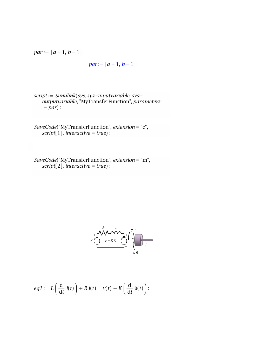
2.3 Example: DC Motor
Consider the classic example of the simplified DC motor. Using the built-in functionality
of the DynamicSystems package in Maple, you can define the system model, and then
visualize and simulate it before saving the code.
This example demonstrates how to define, analyze, and export a system programmatically.
1. In a new Maple worksheet, define the system model.
Differential Equation Model:
>
Page 27
2.3 Example: DC Motor • 21
>
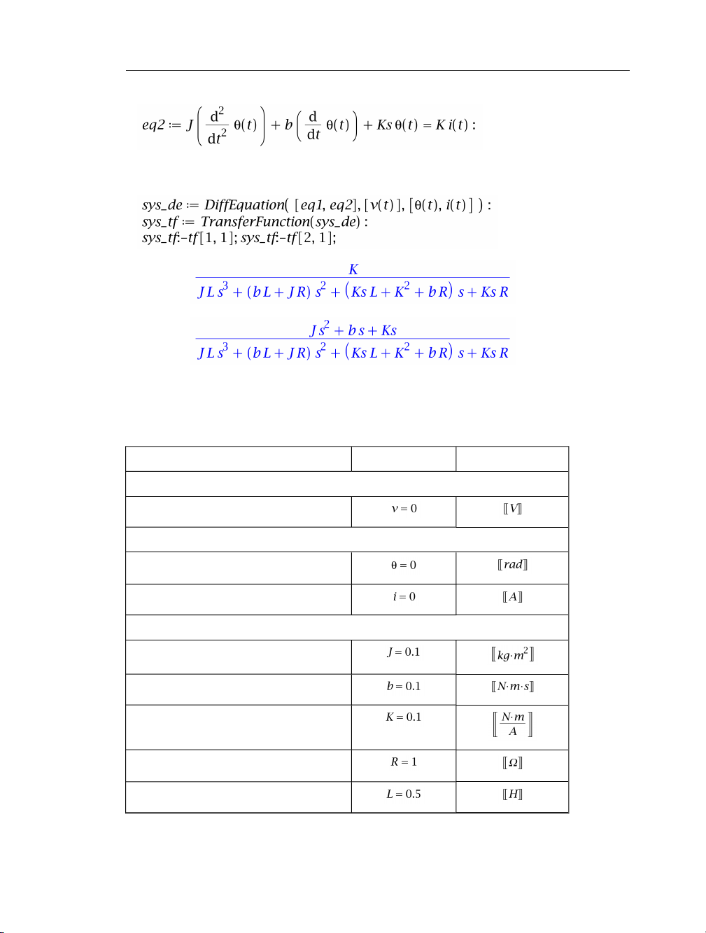
Transfer Function Model:
>
(2.4)
In place of the above commands, you could use the PrintSystem command to display each
part of the model.
2. Specify the parameters in the model.
Units(Initial) ValueDescription
Input Variables
Applied voltage
Output Variables
Motor shaft angular position
Motor current
Parameters
Moment of inertia of the motor
Damping of the mechanical system
Electromotive force constant
Motor coil resistance
Motor coil inductance
Page 28

22 • 2 Creating and Exporting Mathematical Models in Maple
Units(Initial) ValueDescription
External Spring Load Constant
>
>
3. Generate and save the source code as a .c file and MATLAB .m file.
>
>
>
With the basic tools shown in this guide, you are now ready to use the MapleSim Connector
to solve many system design problems. Enter ?DynamicSystems and ?SimulinkConnector
at a prompt in a Maple worksheet for more information about the commands used in this
guide.
Page 29

Index
D
DynamicSystems object, 17
Creating and Exporting Programmatically, 19
Transfer function, 19
I
Inputs and outputs, 7
M
MapleSim Connector Examples Palette, 2
Mathematical model, 17
MATLAB
Setup, 1
S
Simulink, 15
Subsystem
Creating, 6
Subsystem parameters, 11
System object, 17
T
Templates
DynamicSystems, 17
Simulink Block Generation, 2, 13
23
Page 30

24 • Index
 Loading...