

Page 1
SPS-8250/SPS-9250 SWITCH MODE POWER SUPPLY
USER’S MANUAL
INTRODUCTION
The SPS-8250/SPS-9250 Switching Mode DC Power Supply provides high power output with its
small size and lightweight. It is suitable for a variety of uses, especially for DC operated radio equipment
source from an AC outlet and providing variable voltages of 3V to 15V under 25A continuous operation.
Please read through this operation instruction carefully and follow the instructions to prevent from
abuse or misuse. This manual must be kept for reference at anytime in need.
FEATURES
1. Lightweight and Small Size: Switching mode power supply has the advantages of lightweight and
small size. Comparing with linear mode power with the same power output, it is much lighter and
smaller.
2. High Efficiency: The unit is operated with efficiency over 80% under the best condition.
3. Overload Protection: The constant current circuitry is adopted to prevent from overload. The overload
indicator will be lighted up when the unit is overloaded.
4. Over Temperature Protection: The over temperature circuitry is functioned when the unit is over a
certain high temperature to prevent the unit from damage by the high temperature. When the circuitry
is functioned, the output voltage and current will drop down to a safety value and the overloaded
indicator will be lighted up.
5. Over Voltage Protection:
by abnormal high output voltage.
6. High RFI Stability: The high protection circuitry against RFI (Radio Frequency Interference) provides
a stable operation.
7. Variable Voltage Output: The variable range of output voltages from 3V to 15V enables good fits
with various uses.
The over voltage circuitry protect the unit and the loading equipment from damage
PANEL DESCRIPTION
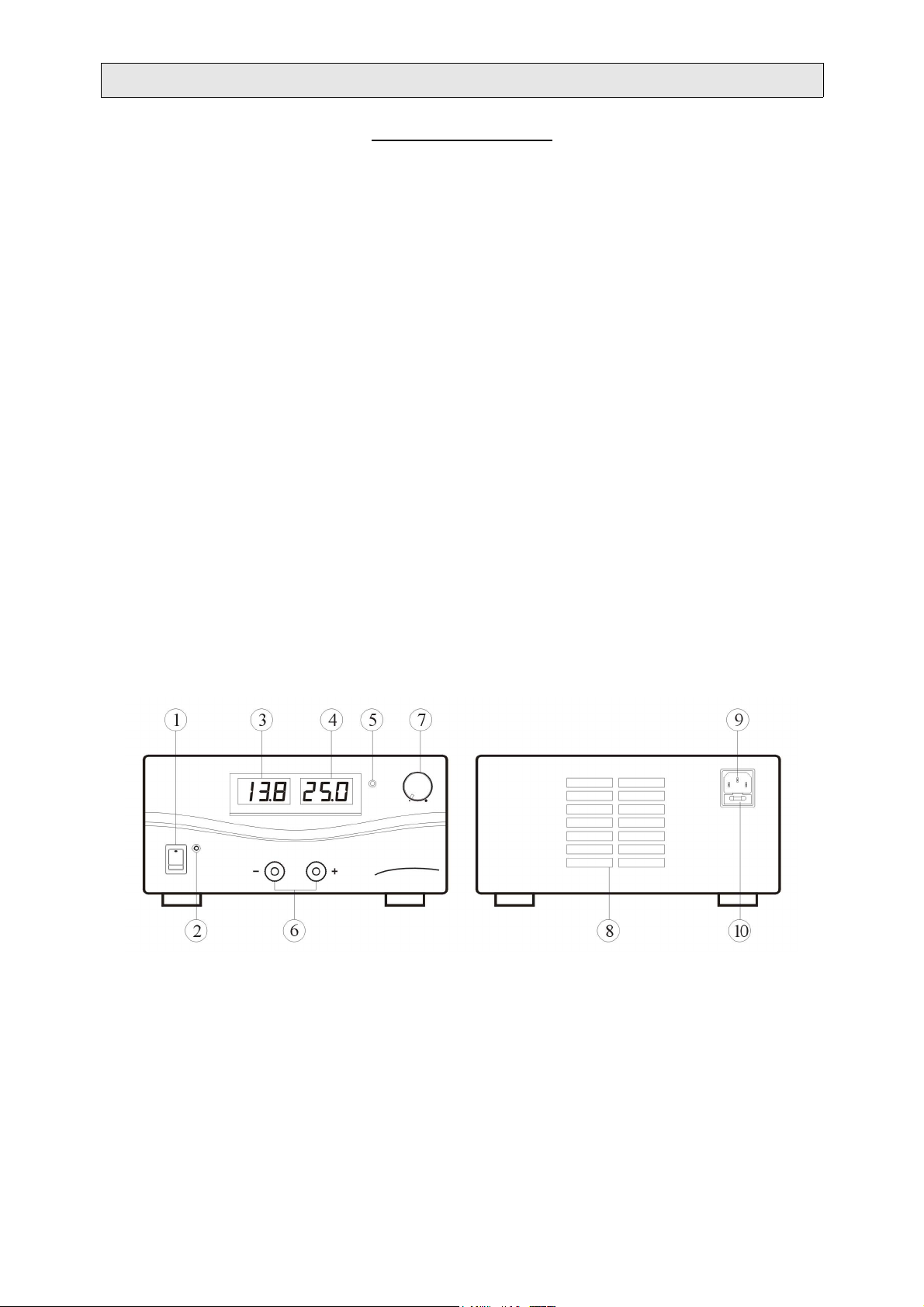
1. On/Off Switch 2. Power Indicator
3. Voltmeter 4. Ammeter
5. Overload Indicator 6. Output Terminal
7. Output Voltage Adjustment knob 8. Cooling Fan Air Intake Window
9. Power Input Connector 10. Fuse Holder
Note: The fixed 13.8Vdc output selection switch is placed at the bottom of unit. It used to select the
output voltage to fixed 13.8V or adjustable output 3-15V (controlled by adjustment knob).
INSTALLATION
1. Make grounding the unit to prevent from electric shock at high voltage caused by leakage or
lightning.
2. DO NOT place the unit in high humid, dusty and/or sunshiny places.
Page 2
3. Place the unit in a location where allows free air circulation.
4. DO NOT place the unit close the TV sets or CRT monitor.
5. Couple with an AC outlet directly, as source via distribution cables may heat plugs and cable.
6. Put the unit horizontally for accurate meter readings.
Note: For Indoor Use Only.
CAUTION
1. DO NOT use the unit for the equipment requiring higher current input than the designed value
otherwise damages the unit.
2. DO NOT replace the fuse before ceasing problems and the assigned value of fuse must be used in
place.
3. If the external flexible cable or cord of this transformer is damaged, it shall be replaced by a special
cord or assembly available from the manufacturer or his service agent.
SAFETY PRECAUTIONS
1. NEVER remove the metal cover of the power supply while AC power is connected.
2. NEVER touch the unit when your hands are wet.
3. NEVER operate the unit if foreign materials such as metallic objects, water, or other debris have fallen
inside. Contact your dealer for check and repair.
4. NEVER operate the unit that was being damaged, as the voltage regulation circuitry may have been
disabled. The resulting high voltage could damage your equipment.
5. NEVER allow foreign objects to touch the DC Power Output Terminals.
6. If you have the need to inspect the interior of the unit, let it to cool down completely, as some
components may be enough to burn your hand in the event of component failure.
7. NEVER block the cooling fan air intake window.
CONNECTION AND OPERATION
1. Make sure the AC power source fits the input of voltage unit labeled and plug it in the AC outlet.
2. Turn ON the unit and adjust the output voltage to match with the input voltage of the equipment. Then
turn OFF the unit.
3. Connect the equipment to the unit. Red (+) is connected to the positive polarity input of the equipment
and Black (-) is connected to the negative polarity input of the equipment.
4. First turn ON the unit and then turn the equipment ON.
5. When and operation is finished, turn off the equipment first and then turn OFF the unit.
SPECIFICATIONS
SPS-8250 SPS-9250
OUTPUT VOLTAGE: 3-15Vdc Adjustable or Fixed 13.8Vdc (Selectable)
OUTPUT CURRENT: 25A
RIPPLE AND NOISE: 5mV
LINE REGULATION:
50mV (±10% Variation)
LOAD REGULATION: 200mV (0~100% Load)
POWER SOURCE: 230Vac/50Hz~ (or On Request)
METER TYPE: Analog Digital LED
DIMENSION (W×H×D):
220 × 110 × 225 (mm)
WEIGHT: Approx. 3.0Kg
r.m.s
Rev1.0 09/2006
7673-8250-0010
 Loading...