

Page 1

HCS-3300/3302/3304 USB
Remote Programmable Laboratory Grade Switching Mode Power Supply
User Manual
1. INTRODUCTION
Since the intr o duc ti o n o f HCS s er ie s p o wer s upp li es in 2009, we ha ve made n u mer o us i mp ro ve me nt wit hin the limits of
the original hardware modules, firmware and software framework.
In the upgraded version of HCS series power supplies, both the hardware and the firmware have been modified, the
application software has a completely design in concert with the value added features.
Added features which can be done on the unit panel.
1. Reset no load current to zero on current meter.
2. Reset the 3 presets to factory default
2. WARNING
• Do not use thi s power supply near wat er.
• Do not ope rate or touch t his power supply with wet hands.
• Do not open the casing of the power supply when it is connected to ac mains.
• Refer all servicing to qualified service personnel only.
• Before replacing the AC fuse at AC socket, find out and clear up the cause first.
• Replace the AC fuse with the same type and rating as the original fuse.
• The max. output voltage of Model HCS-3304 is over 60VDC, avoid touch the metal contact part of the output
terminals.
• This power s upply is de s igned for us ing in non -cascade e nviron ment. It is not recommended to connect two or more
power supplies in parallel or in series.
• Analogue Remote Control or Remote Programming via USB function is only suitable for stand-alone one unit
operation.
• Do not use this power supply with electrical motors, solenoid or inductive load that generates a back EMF and
voltage transient which may damage the power supply
3. CAUTION
• Use a grounded 3 pin AC source.
• This unit is for indoor use onl y.
• Do not operate or place this unit in a humid, dusty, in direct sunlight location or near any heat source.
• Before plugging into local AC mains, check with the rating label at the back of the unit.
• Do not block any ventila tion openi ngs of the unit.
• This unit must be used within the specified rating, regular excessive continuous loading may cause damage to the
power supply.
• The gauge size of input power cable must be at least 0.75mm
3m.
2
and the total length of power cable must not exceed
4. OPERATION ENVIRONMENTAL CONDITION
• 10-80% R.H.
• Altitude up to 2000m
• Installation category: CAT 2
• Pollution degree: 2
• Mains supply voltage fluctuation up to ±10% of the normal voltage
Page 2
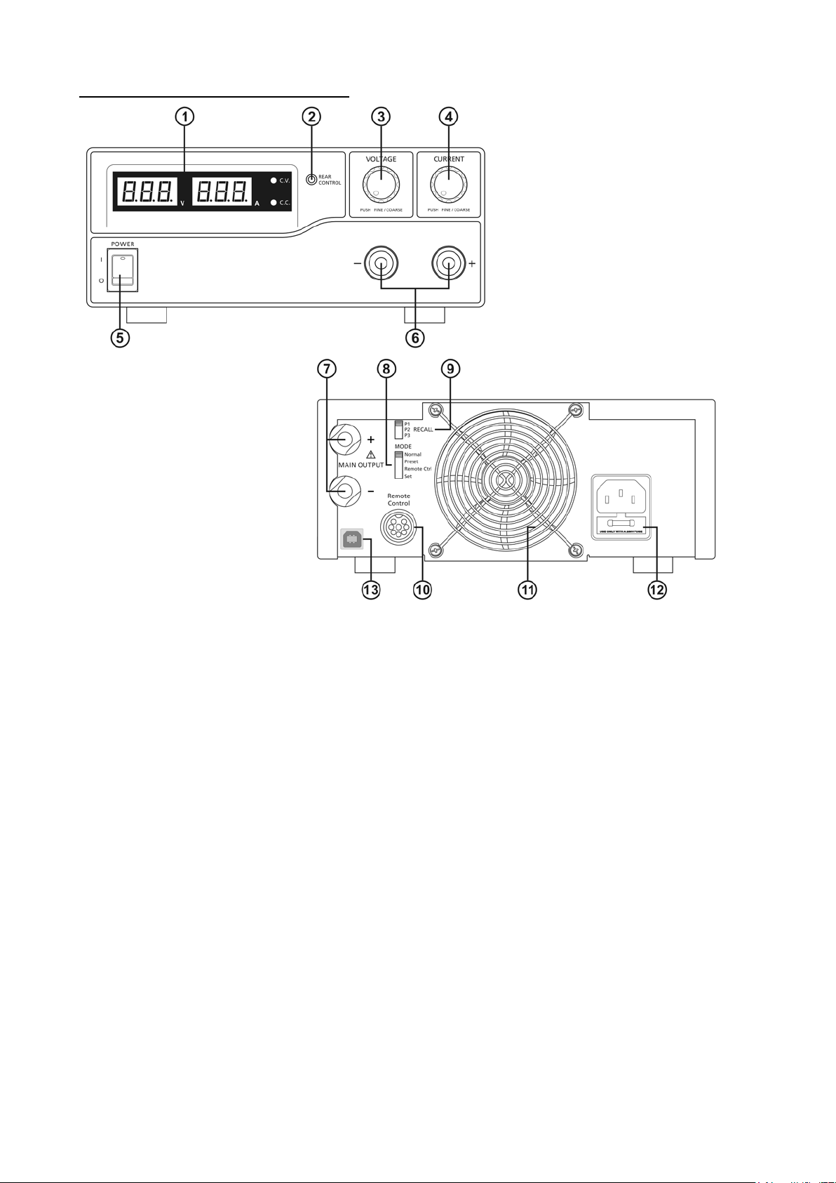
5. CONTROLS AND INDICATORS
Front
Rear
(1) LED panel meter display with CC/CV Indic tor
(2) Rear Control Indicator (light s up when using Preset/ Remote Control/ Set mode)
(3) Output Voltage Control Knob (control both the main and auxiliary output voltage)
(4) Output Current Control Knob (cont r ol both the main and auxiliary output current li mit)
(5) Power ON/OFF Switch
(6) Aux. output t erminal (max 5A)
Note: HCS-3300: The total rated current (Aux.+Main) is 30A
HCS-3302: The total rated current (Aux.+Main) is 15A
HCS-3304: The total rated current (Aux.+Main) is 8A
(7) Output Terminal (Rated 30A for HCS-3300/ Rated 15A for HCS-3302/ Rated 8A for HCS-3304)
(8) Mode Selection Switch (Normal, Preset, Remote Control, Set Modes)
(9) Recall Selection Switch
(10) Remote Control Terminal
(11) Cooling Fan Air Intake Grille
(12) AC Input Plug
(13) USB port
(for access to computer to run cyclical operation with programmable voltage, current, period time and cycle)
Page 3
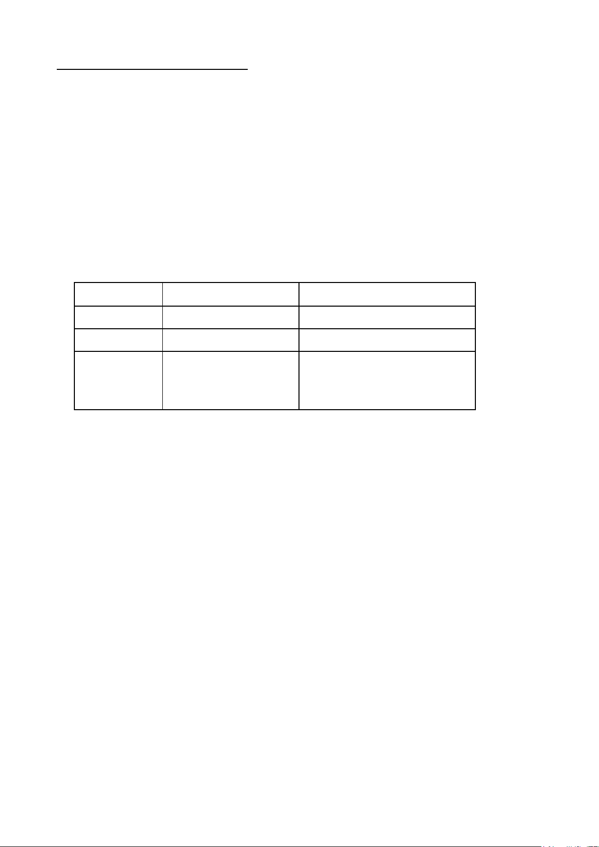
6. CONTROL MODE SELECTION
Recall No.
Output Voltage
Output Current
P1
5V
Maximum
P2
13.8V
Maximum
P3
HCS-3300: 15V
Maximum
There are 4 modes, Normal, Preset, Set and Remote Control mode for the power supply.
Slide the Mode Selection Switch (8) to yo ur desired Mode.
The power supply is factory preset to Normal Mode with maximum current level CC.
6.1 Normal Mode
This is the factory preset mode and the power supply output V, I, are controlled by the dual act i on volume knobs.
Push the kno bs to toggle the coar s e and fine tuning, notic e the subtl e changes in brightness of related LED.
Adjust the knobs to your desired values by trying coarse and fine tuning.
To check the p reset current level, just turn t he Current Knob lightly in any direction.
The display will resume its normal brightness after few seconds to double confirm your adjustment.
6.2 Preset Mode
a. In this mode, the Rear Contro l Light is on to indicate panel V & I controls are de-activated.
b. There are 3 preset output P1/ P2/ P3 at the Recall Selection Switch (9)
c. The preset values are factory set as following table.
d. End user can set his own output rating, please refer to paragraph 6.3
HCS-3302: 25V
HCS-3304: 55V
6.3 Set Mode – First enter into the Set Mode by pushing Switch (8) to Set Mode slot.
The power supply is then ready to be preset.
6.3.1 To define the preset output P1/ P2/ P3.
a. Select the Recall Switch (9) to the position P1, P2 o r P3 which you want to set
b. Adjust the front panel voltage control knob to set your desired voltage value
c. Adjust the front panel current control knob to set your desired current limit value
d. Repeat the procedure for remaining recalls P1, P2, P3 if desired.
e. Move Mode Switch (8) from Set to Preset position to confirm your settings.
Remarks:
All the set values in the presets will be kept even after the po wer supply has been tuned off.
Always check output voltage of Pr esets before connect to Load
To check the preset values, move Mode Switch (8) to Preset position
Move the Recall Switch (9) to P1, P2 or P3.
The V and I settings of corresponding RECALL P1, P2, P3 will be show on the panel meters.
It is more ease to setup these preset values by using PC software. After set values in PC software and save. Use
Recall switch to use it.
6.4 Analogue Remote Control Mode
To contro l the output vol tage and current by remote control connector (10)
Please refer to paragraph 8
Page 4
7. Using the power supply
Model Number
Output Voltage Range
Total Rated Current
HCS-3300
1 ~ 16V
0 ~ 30A
HCS-3302
1 ~ 32V
0 ~ 15A
HCS-3304
1 ~ 60V
0 ~ 8A
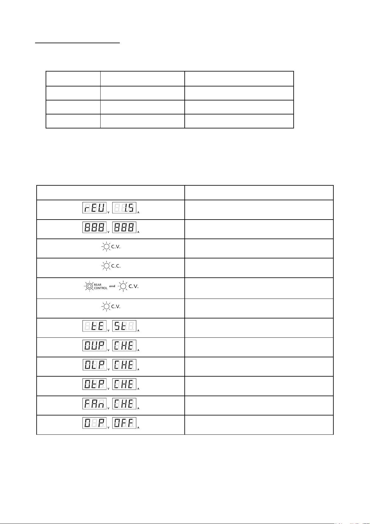
Self test display and Sequence
Test contents
7.1 This series has 3 models. Make sure you have used the correct one.
They have different output volta ge range and current as following:
7.2 Check the rating label of the power supply and make sure it complies with your AC mains voltage.
Connect the power supply to the AC Mains using the provided power cord.
Make sure the Mode Switch (8) is at Normal Position.
Below table to show the self test sequence
To show software version
Segment check
C.V. Indicator check
C.C. Indicator check
Rear control indicator check
Return to C.V.
Start to check
Over voltage protection check
Over load protection check
Over temperature protection check
7.3 The power supply will perform a series of self chec ks when it is switched on.
The LED and o t he r i nd ica to r s on t he fr o nt pa ne l wil l b e o n by turn. W he n t he co o li ng fa n is being c he cke d, a hi gh
speed wind noise can be heard.
After the self checks, the CV, V and A LED indicators are lit up displaying voltage and 0.0 current. To find out
about the set C C current level , just tur n the curr ent contr ol knob o ne click i n either di rectio n. The cur rent disp lay
returns to 0.0 after a few seconds.
Output off (remote control mode)
Fan check
Page 5
7.4 Using the control knobs
The rotary encoder control knobs have fine and coarse tuning with clicking movement.
Push the knobs to toggle between coarse and fine tuning, notice the subtle changes in brightness of related LED. .
Adjust the knobs to your desired values by trying coarse and fine tuning.
The display will resume its normal brightness after few seconds to confirm your adjustment.
7.5 Connect the equipment to the power supply. Red (+) is connected to the positive polarity input of the equipment
and Black (-) is connected to the negative polarity input of the equipment.
7.6 Switch on the power supply first and the panel meter & green CV Indic ator should l ight up again.
7.7 Switch on the equipment and the panel meter & green CV Indicator should still r emain in green.
7.8 You can now operate the equipment.
When an operation is fi nished, switch off the equipme nt fi rst and then switch off the power supply.
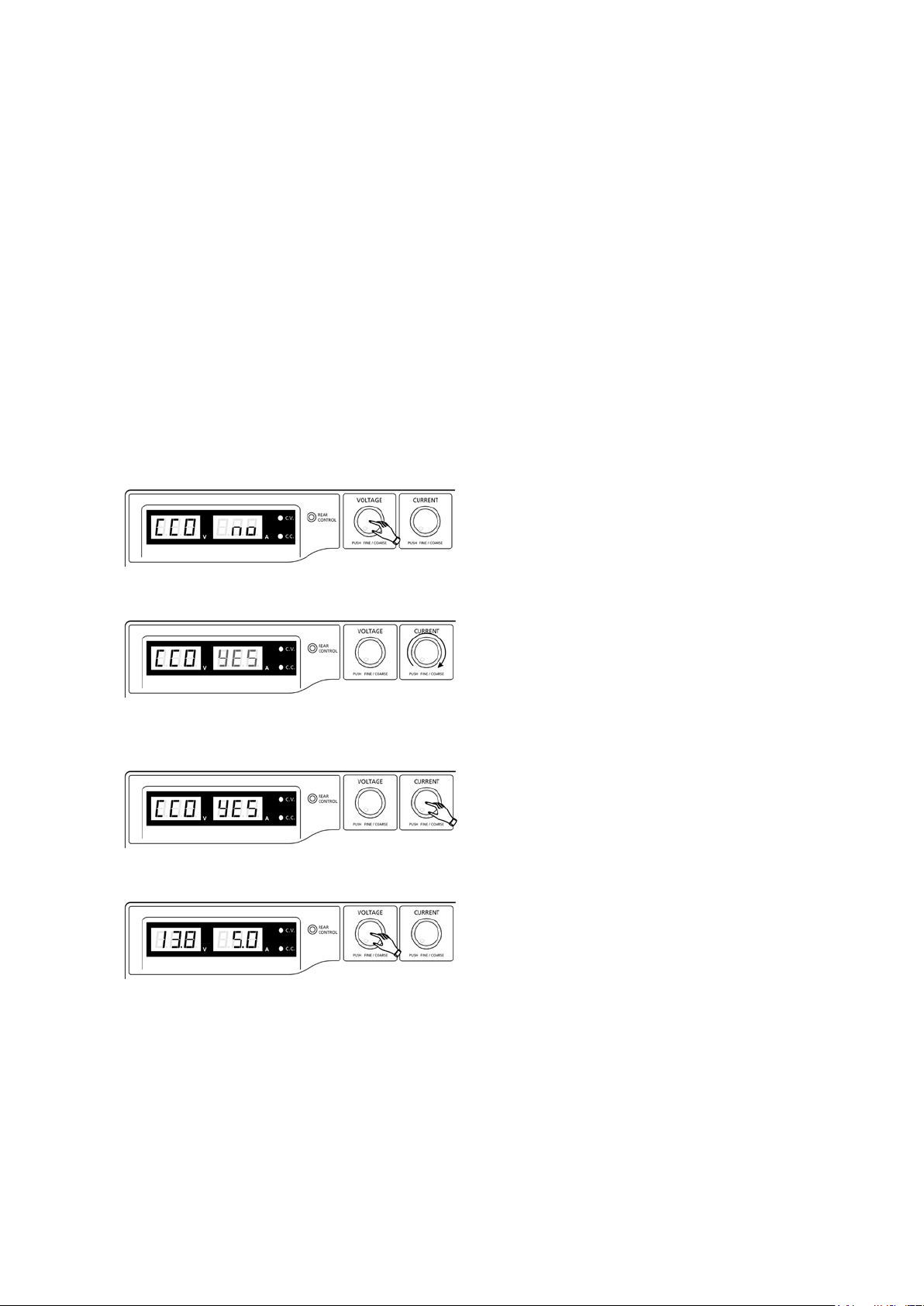
7.9 Manually zeroing Current Meter Offset
The p ower suppl y will auto -zeroing the current meter offset when po wered up. In case it is needed to reset current
meter to zero during test and you do not want to restart power supply. You can manually reset it to zero in menu
mode.
Press and hold Voltage Control Knob for 30s to enter MENU mode. It shows
Rotate Current Control Knob until the Current meter s howing
Then press Current Control Knob once to confirm. The “YES” will be lighted after successful zeroing current
meter offset.
Finally, pr e ss Vo ltage Control Knob to exit MENU mode.
Page 6
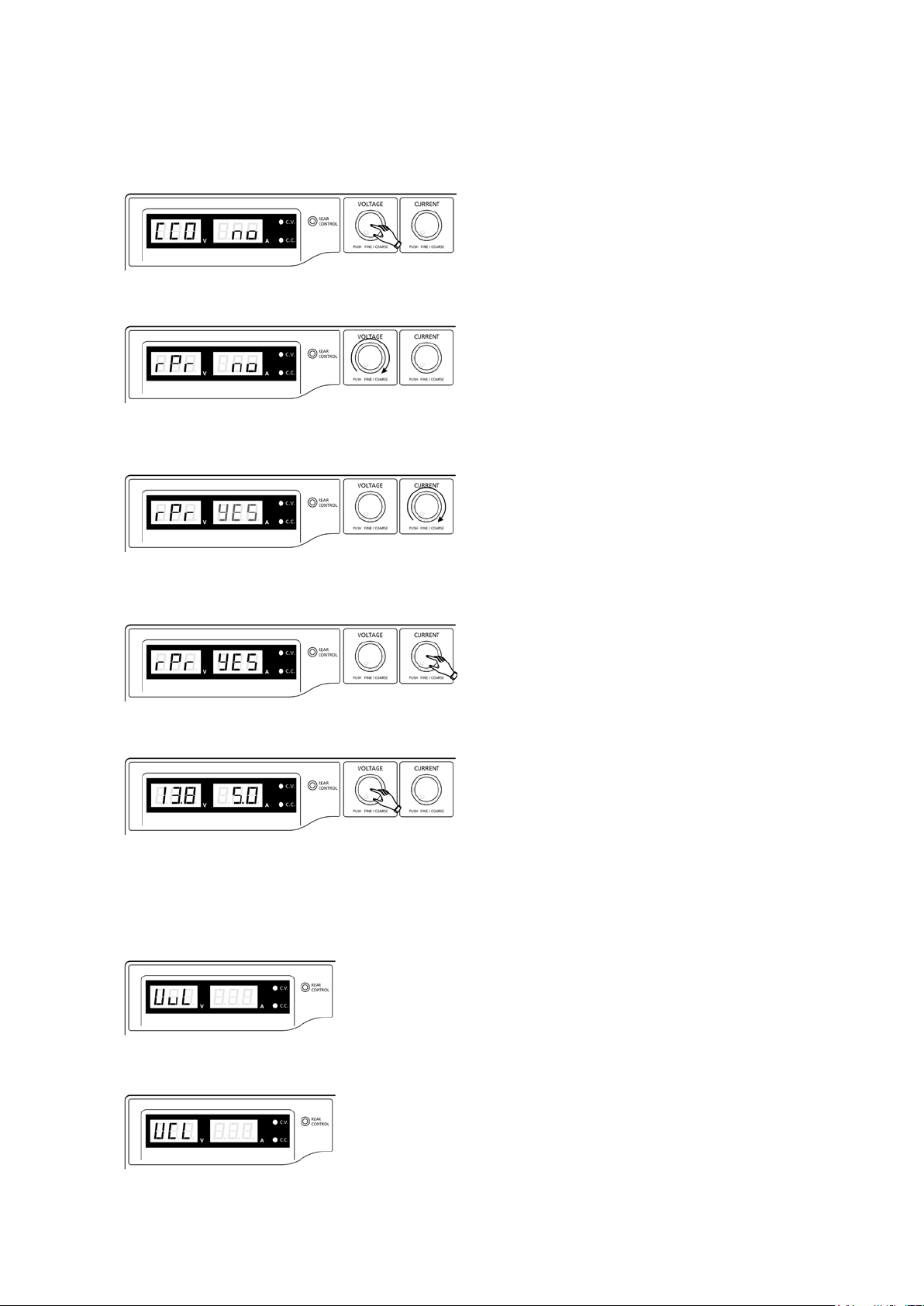
7.10 Reset 3 preset output P1/ P2/ P3 to factory default value
In session 6.3, you learning how to set 3 preset output to you preferred value. In case you need to reset it to factory
default, you can do it in MENU mode.
Press and hold Voltage Control Knob for 30s to enter MENU mode.
Whe n it is showi ng “CCO”, rotate Voltage Control Knob until Voltage meter showing “rPr”.
T he Current mete r is showi ng “no” at this time. T hen rotate Current Control Knob until Current meter sho wing
“YES”.
Pr ess Current Control Knob once to confirm. The “YES” will be lighted after preset output being reset to factory
default value.
Finally pre ss Vo ltage Control Knob to exit MENU mode
7.11 Upper V oltage Limit (UVL) and Upper Current Limit (UCL)
The power supply has Upper Voltage Limit and Upper Current Limit setting. These value can ONLY be set
through PC software.
Whe n increasing output voltage setting and reach set UVL value. The vo ltage disp l ay will show
Whe n increasing output c urrent setting and reac h set UCL value. The current display will show
Page 7
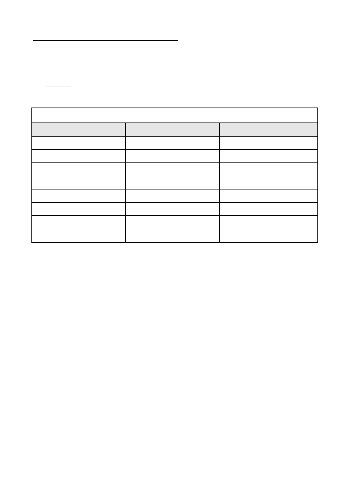
8. ANALOGUE REMOTE CONTROL MODE
Remote Socket Pin Assignment for external variable voltage source
PIN
FUNCTIONS
REMARKS
1
Internal DC +5V
Less then 50mA
2
Voltage Adj ust
0 - 5V
3
Current Adjust
0 - 5V
4
Ground
5
Output OFF
Short to Ground
6
N.A. 7
N.A.
8
N.A.
There are two methods for remote control of current and voltage adjustment.
Both methods require both the current remote control part and the voltage remote control part to be set up and be in
used at the same time in order for analogue remote control mode to be functional.
Otherwise unit will be in CC mode all the ti me and the analogue remote control will not be functional.
8.1 Method A Using two external variable DC voltage sources
Remote Socket Pin Assignment for external variable voltage source PIN FUNCTIONS
CC current setting by remote contro l.
Short circuit the main output with 12AWG wire.
Adjust the CC current using external power supply connected to Pin 3.
Output voltage setting by remote c ontrol
Check the output voltage range of t he power supply by varying the external volta ge source connected to Pin 2.
Page 8
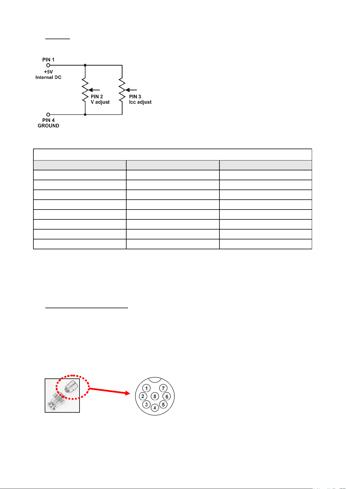
8.2 Method B Using two 0 – 5K Ohm variable resistors
Remote Socket Pin Assignment for variable resistor
PIN
FUNCTIONS
REMARKS
1
Internal DC +5V
Resistor end
2
Voltage Adj ust
Variable part of resistor
3
Current Adj ust
Variable part of resistor
4
Ground
Another resistor end
5
Output OFF
Short to Ground
6
N.A. 7
N.A.
8
N.A.
Pin numbers are marked
on
Two variable resistors must be set up at the same time in order for the re mote co ntrol to be functional.
Remark: variable resistors 5Kohm.
CC current setting by remote contro l.
Short circuit the main output with 12AWG wire.
Adjust the CC current se tting usi ng the 0-5k Ohm variable resistor.
Output voltage setting by remote c ontrol
Check the output voltage range of the power supply by adjusting the 5Kohm variable resistor.
8.3 Remote Output ON/OFF Control
This remote output on/off control can be activated in any of the modes Normal, Preset, Remote and Set mode.
A. By default, Pin 5 is open and output is on.
B. Shorting Pin 5 to Pin 4 (ground) and output is off.
C. When output is off, the C.V. & C .C. LED wi l l flash. The current output voltage and cur rent setting will show on
the panel meter.
D. You also can adjus t the output by voltage & current control knob to your des ired value when output is off.
Remark: using the 8pin remote pl ug provided and connect with 22AWG wires.
CAUTION !
The allowable fastest switching On/Off frequency is 10 times per second.
When the On/Off frequency is over 10 times per second, the power supply may not work normally and protections may
be triggered.
the black portion.
Page 9
9. FAULTS AND TROUBLE SHOOTING
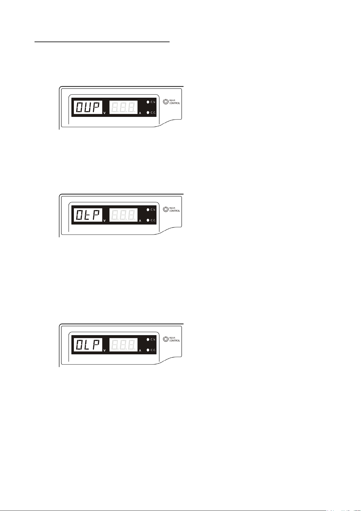
9.1 OUP: Over Voltage Protection
This unit has a built-in tr acking over voltage p rotection fe ature. In the event of output voltage becoming
greater than the set value (see specified ra nge from specifications table), protection will be triggered and the
o utput p ower will be cut off and OUP warning appears as below.
To reset the warning, s witch off the unit and remove all loading.
Switch the unit back on again and it should resu me normal operation.
If this problem persists, please contact and consult with your agent.
9.2 OTP: Over Temperature Protection
There is a thermo sensor inside the unit to monitor and to prevent the unit to ge ts too hot inside. At OTP, there
is no outp ut and the following warning will a ppear on the LED display.
When you get this warning, switch off the unit and remove all loading.
Check your load and output setting. Allow the unit to cool down for at least 30 minutes.
Check if any of the ventilation is bl ocked, check enough cle arance around power supply.
Listen carefull y for the shor t wind noise from the cooling fan when you turn on the unit again.
I f you cannot hear thi s routine self te st wind noise on swit ch on, the fan is fa ult and do not use t he power
supply, contact your agent.
9.3 OLP: Over Load Protection
Normally the overload protection is sustained by the CC constant current mode.
When the CC mode fails and goes undetected, it may cause serious damage to your test piece or load.
The OLP is to minimize the extent of damage to your loads as power supplies do fail someday.
Switch off your power supply as soo n as you see t his warning as shown below.
To reset this warning, switch off the u nit and remove all loading.
Switch the unit back on a gain and d ouble check with caution.
If this problem cannot be fixed, please contact and consult with your agent.
Page 10
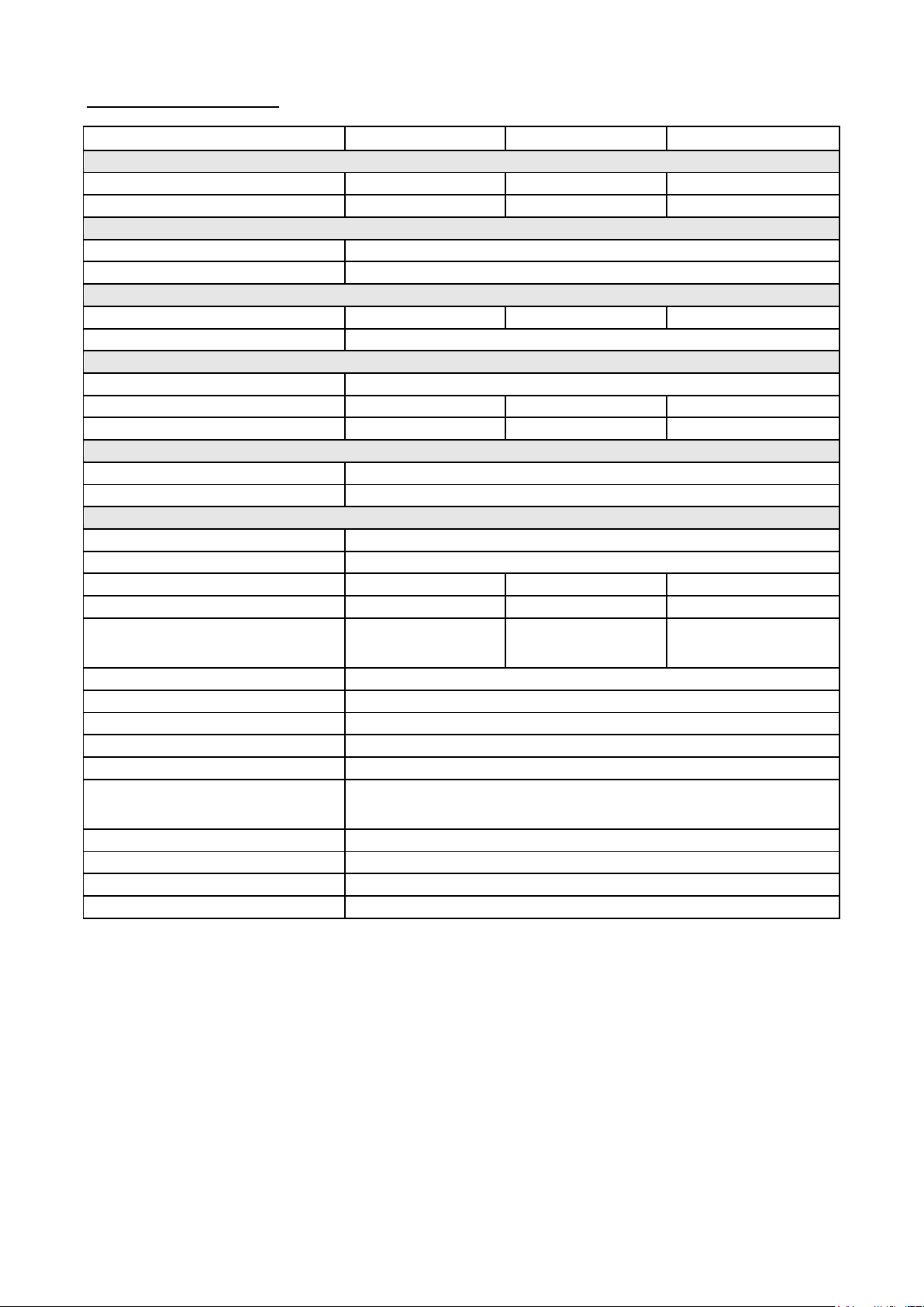
10. SPECIFICATIONS
Models
HCS-3300
HCS-3302
HCS-3304
Output
Variable Output Voltage
1 - 16VDC
1 - 32VDC
1 - 60VDC
Variable Output Current
0 - 30A
0 - 15A
0 - 8A
Voltage Regulation
Load (10-100% Load)
50mV
Line (170-264VAC Variation)
20mV
Current Regulation
Load (10-90% Rated Voltage)
150mA
100mA
100mA
Line (170-264VAC Variation)
50mA
Ripple & Noise
Ripple & Noise (r.m.s.) Voltage
5mV
Ripple & Nois e (peak-peak) Voltage
50mV
50mV
100mV
Current Ripple & Noise (r.m.s.)
50mA
20mA
10mA
Meter Type & Accuracy
Voltage Meter
3 Digit LED Display ±0.2% +3 counts
Current M eter
3 Digit LED Display ±0.2% +3 counts
Other
Input Voltage
200 – 240VAC 50/60Hz~ (or on request )
Full Load Input Current
2.5A
Efficiency
85%
86%
88%
Switching Frequency
65 – 85Khz~
75 – 95Khz~
65 – 85Khz~
O/P 1-5V: set voltage +2V
O/P 1-5V: set voltage +2V
O/P 20-30V: set voltage +4V
O/P 1-5V: set voltage +2V
O/P 20-60V: set voltage +4V
Transient Response Time (50-100%Load)
1.5ms
Power Factor Control
Power factor correction >0.95 at optimal load
Cooling Method
Thermostatic Cont rol Fan from Zero to f ull speed
Protections
Overload, Short Circuit by Constant Current, Output Tracking Over Voltage, Over Temperature
Special Features
3 User defined VI preset, Remote control V, I and output on-off
Max. 20 presets of V & I
Max. preset cycle 999
Accessories
User Manual, Application Software, USB cable
Approvals
CE EMC: EN 55011, 55022 LVD: EN 60950, 61010
Dimensions (WxHxD)
200 x 90 x 215 mm 7.9 x 3.5 x 8.5 inch
Weight
2.6 kg 5.7 lb
Tracking Over Voltage Protections
Preset Cycle P r ogramming
O/P 5-15V: set voltage +3V
Max. preset t ime 99min. + 59sec.
O/P 5-20V: set voltage +3V
O/P 5-20V: set voltage +3V
Page 11
11. PC Interface Control
Support OS: Windows XP/Vista/7 (32bits/64bits)
Driver: Silicon Lab CP210x USB driver
(Included in CDROM folder “USB CP210x Drivers V6.6.1 for Win_XP_S2K3_Vista_7”)
Execute Program: run “<CDROM Drive>:\pscs\pscs.bat”
A. Main Display
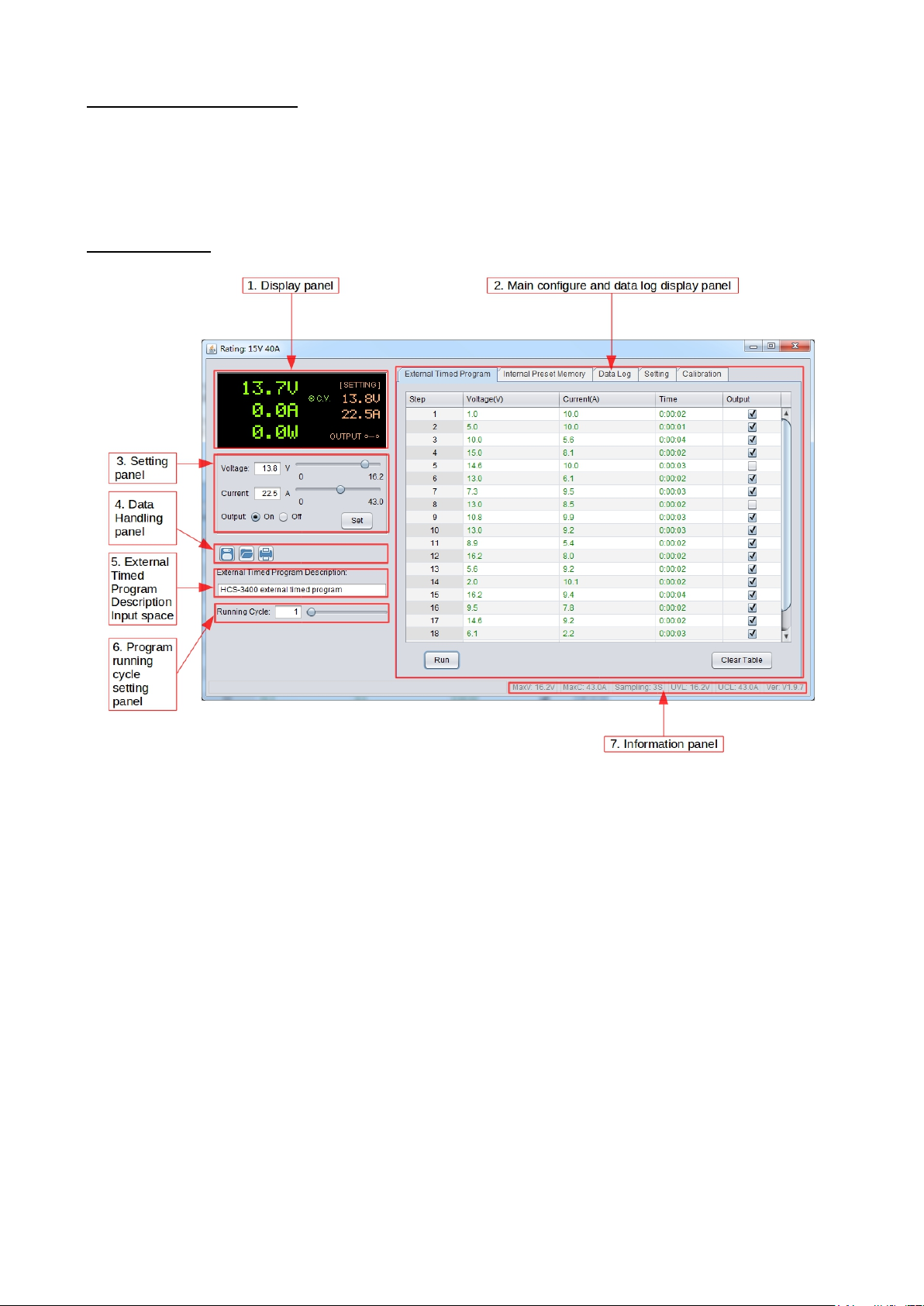
The Main interface divided into 7 panels.
1. Display panel – use to display real-time information of power supply.
2. Main configuration and data log display panel – use to change general setting of program and display data log.
3. V oltage and C urrent setting panel – use to set inc ident output value and output On/Off.
4. Data handling panel – use to save, load and print data.
5. Exter nal Timed Program Description input space – use to enter d escription of External Timed Program.
6. Program running cycle setting panel – use to set running cycle for External Timed Program.
7. Information panel – use to d isplay Maximum voltage/ current, Sampling time , upper voltage/ current limit
and software version.
Page 12
B. Display panel
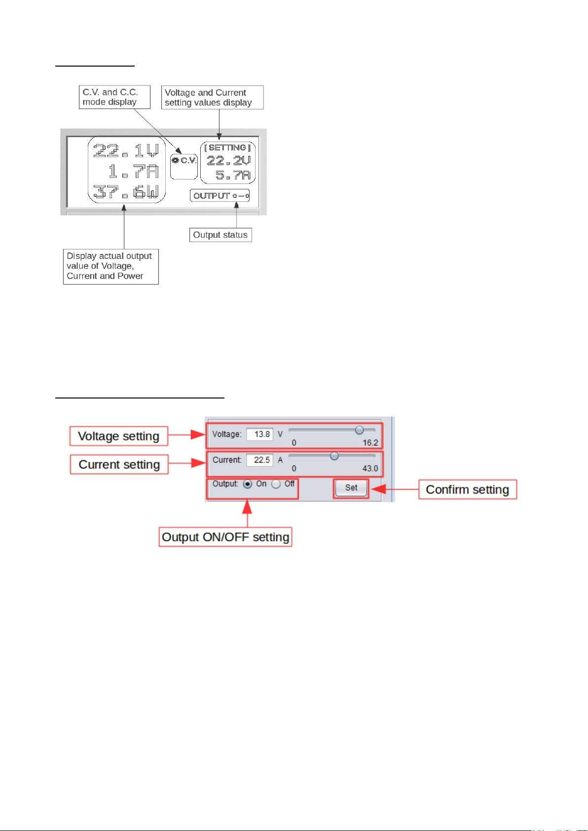
The display show following in formation
- Output Voltage value
- Output Current value
- Output Power value
- Output On/Off status
- C.V./ C.C. Model
- Setting values
C. Set output value and On/Off st atus
You can directly type the desired o utput volta ge & outp ut curre nt and the n click “Set” butto n to set t he value. Or you
can use slide bar to adjust the value.
Page 13
D. External Timed Program
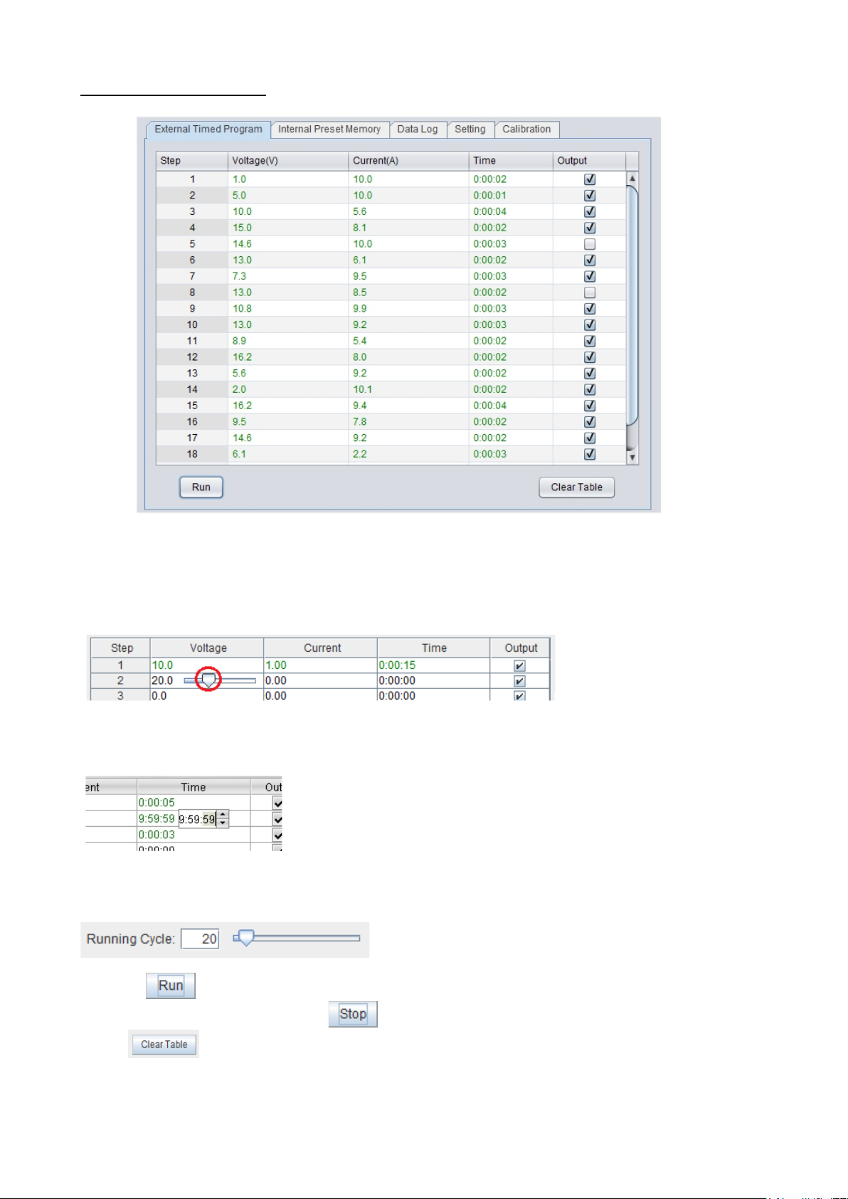
External Timed Program is completely controlled by PC, PC counts the time and changes volta ge a nd cur rent of p o wer
supply.
Select External Timed Program tab to switch to the External Timed P rogram tab.
- Double click on the cell that you would like to set value. For example Step 2 voltage.
- Slide the bar to configure the value.
- Set time for this step to be running. The time range is between 0 to 9hours 59 minutes 59 seconds. You can click
up/down button to change value or directly input value. If the time value is set to 0, this step will be skipped.
- Select running cycle between 0-999. You can use slide bar t o select or directly input value in t ext box. Input 0 means
run the program forever.
- Click on
- In between program run ning cycle, click
- Click
button to start running cycle.
to clear the setting.
button to stop program.
Page 14
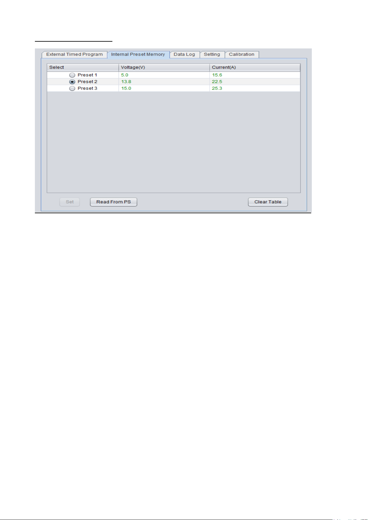
E. Internal Preset Memory
The PC interface remote mode really eliminates the tedious process in keying in groups of entries on the power supply.
Because all the data are displayed together in the monitor, possibility of wrong entry is greatly reduced. Data of
different groups can be classified, stored, exported and retrieved for use at any time.
Furthermore, retrieved data will be in red color if they exceed the present preset limits of voltage in upper voltage level
or current limiting value.
Clear Table ----- Delete all data on the Display Table to ready for new data entry.
Read for PS ----- Get data from the Power Supply.
Page 15
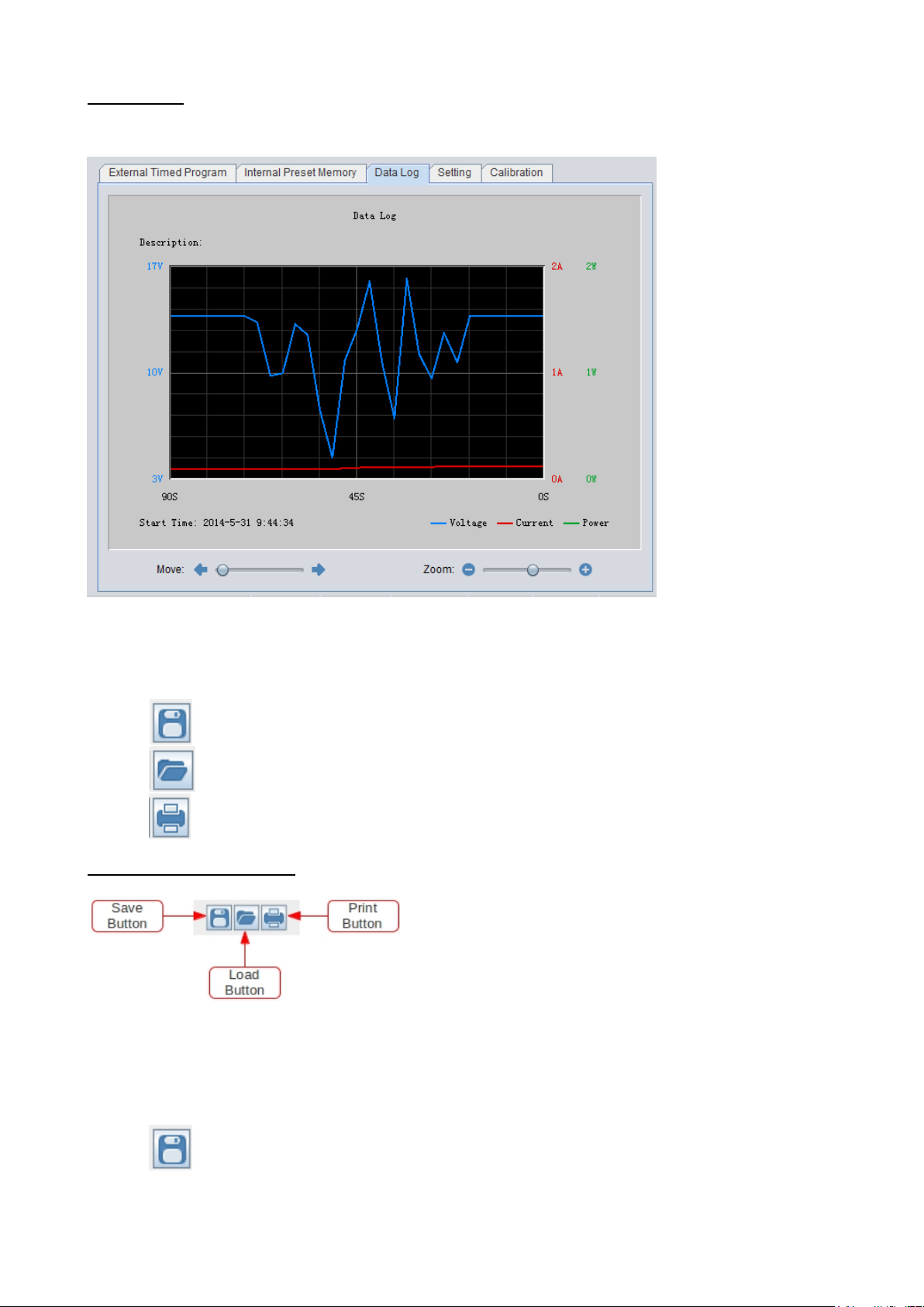
F. Data Log
Data Log window
Data log window is used to displa y outp ut Vo lta ge, Current and Power against time in graphical view.
You can move the diagram left and right by adjust “Move:” slide bar.
You can zoom in/out the diagram by adjust “Zoom:” slide bar.
You can save the data in CSV file for analysis later.
- Click
- Click
- Click
G. Save, Load and print setting
In previous session, the above 3 buttons are used to save, load and print log data. In addition, these buttons can used to
save, load and print setting for External Timed Program and Internal Preset Memory.
First, select tab in Main configure and data log display panel.
to save Data log to CSV file.
to open and load data from CSV file to program for analysis.
to print the setting to print.
When “External Timed Program” tab is being selected, the buttons are used to save and load the setting of External
Timed Program.
- Click
to save External Timed Program setting to CS V file.
Page 16
- Click to open and load setting from CSV file to program.
- Click
- If you want to add description for your setting. Input the descript ion in following “External Timed Program
Description:” space to before save.
to print the setting to print.
When “Internal Preset Memory” tab is being selected, the buttons are used to save and load the setting of Internal Preset
Memory.
- Click
- Click
- Click
H. Setting
to save Internal Preset Memory setting to CSV file.
to open and load setting from CSV file to program.
to print the setting to print
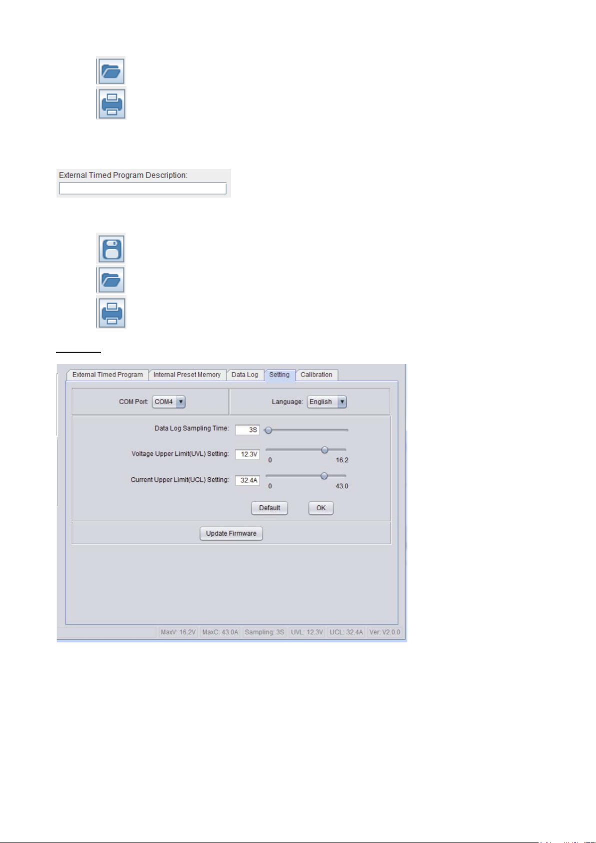
In the setting page, you can do general setting for the program.
The software will automatic detect power super model and COM port used
You can select language for the program
You can select the COM Port for power supply connected
You can set sampling time for data log by adjust slide bar
You can set your output voltage upper limit (UVL) value to further safeguard your low voltage applications.
You can set your output current upper limit ( UCL) value to further safeguard your low current appl i cations.
You can update power supply Firmware (Remark: Only available on system shipped with version 3.1 or above)
* Remark: The UVL and UC L setting will save into power supply. These value can only be set through PC
software.
Page 17
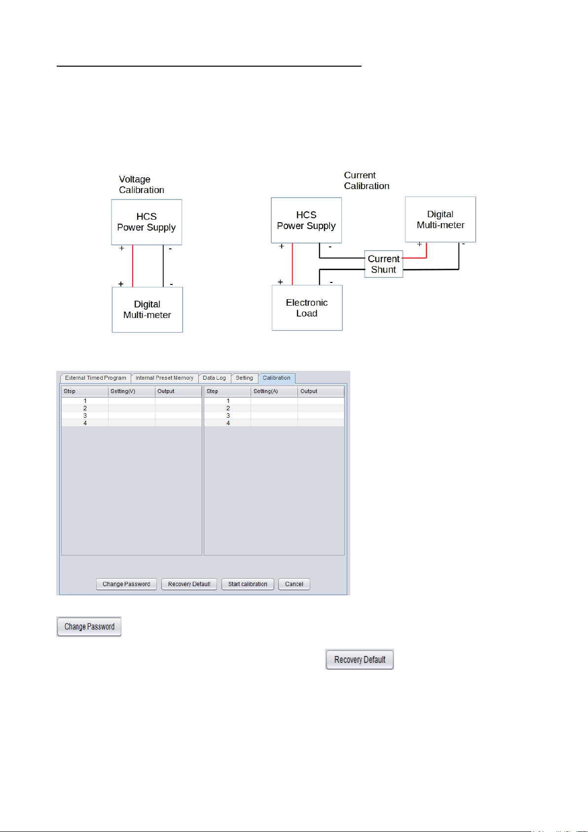
I. Power Supply Calibration (Only available on Firmware 3.1 or above)
* WARNING: IT IS HIGHLY RECOMMENDED THAT THE CALIBRATION IS DONE BY EXPERIENCE
TECHNICAL PERSON
HCS can be calibrated by using Manson PC control software. Digital Multi -meter and Electronic load are required for
calibration.
Please connect as follow for Voltage and Current Calibration.
Click on the calibration page
It need password to entry calibration, the default password is password. After login, you can change password by click
to enter you new password.
You can recovery to default factory shipped calibration by click on
button.
Page 18
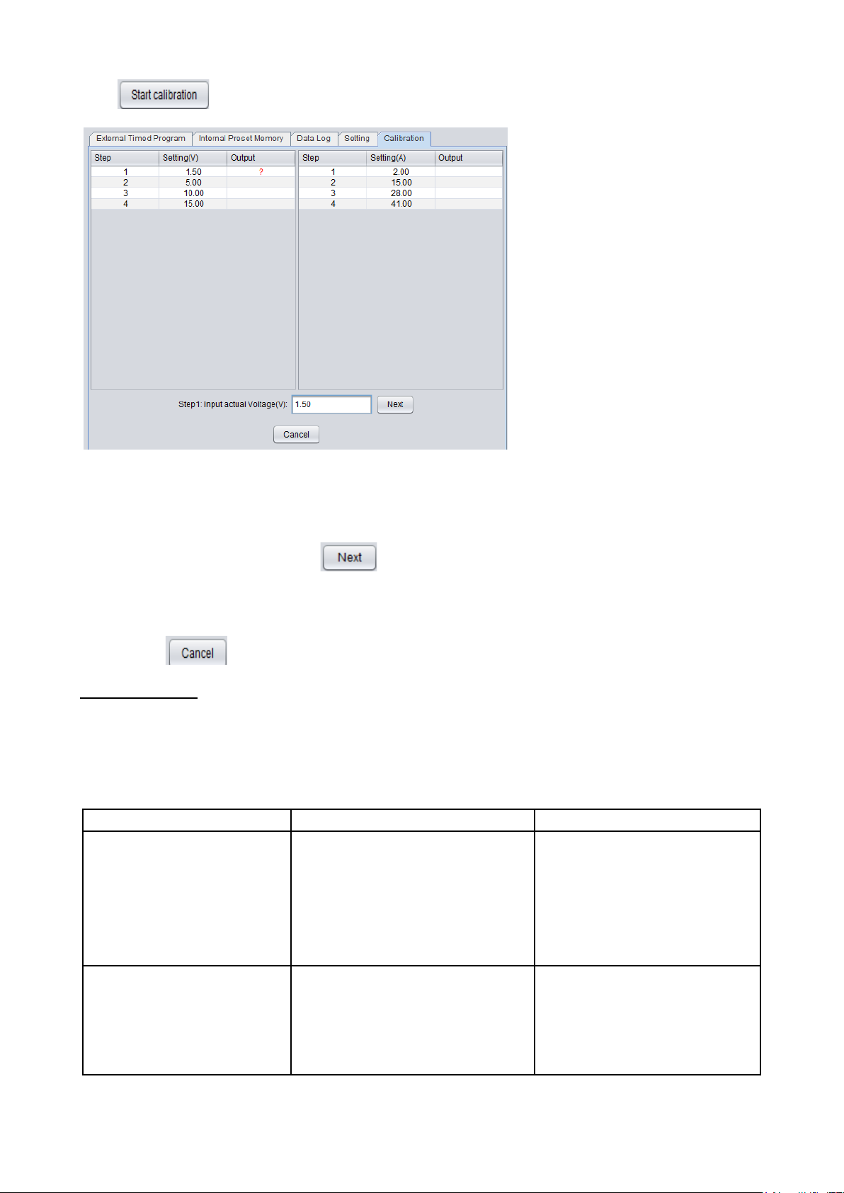
Click to run calibration process.
Command code & return value
Function
Example
Input Command:
Get PS maximum Voltage & Current value
Input command:
Maximum Current is 20.0A
Input Command:
Switch on/off the output of PS
Input command:
Switch on the output of PS
There are total 8 steps for calibration. 4 steps for Voltage and 4 steps for Current. You only need to follow step by step
to finish calibration.
It start from Voltage calibration first. DO NOT CONNE CT LOAD for Volta ge calibr ation . As s ho w in t he ab o ve figure,
the power supply will automatic set output voltage for each step. You need to measure actual output by Digital multi-
meter and input actual Voltage then click
to continuous for next step.
After 4 steps of V oltage calibration, it will s witc h to Curr e nt calibration. It need to CONNECT TO ELECTIONIC
LOAD for current calibration. The calibration steps in similar as voltage calibration.
You can click
to cancel calibration anytime.
J. Co mmand Set
Command line for mat
COMMAND<parameter1><parameter2>... [CR]
Remark:
One decimal place for current value: HCS-3100, 3150, 3200, 3202, 33XX, 34XX, 36XX
Two decimal places for current value: HCS-3102, 3014, 3204
GMAX[CR]
Return value:
<voltage><current>[CR]
OK[CR]
<voltage>=???
<current>=???
GMAX[CR]
Return value:
180200[CR]
OK[CR]
Meaning:
Maximum Voltage is 18.0V
SOUT<status>[CR]
Return value:
OK[CR]
<status>=0/1 (0=ON, 1=OFF)
SOUT0[CR]
Return value:
OK[CR]
Meaning:
Page 19
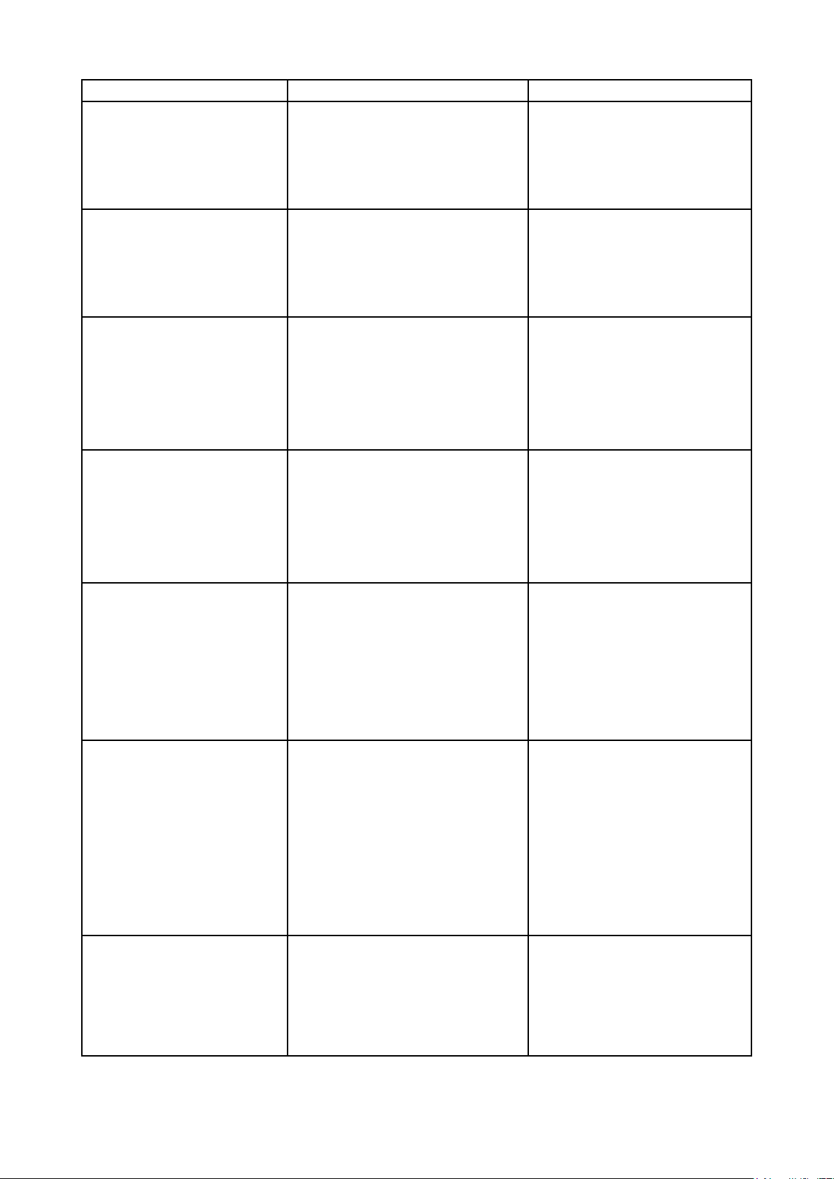
Command code & return value
Function
Example
Input Command:
VOLT<voltage>[CR]
Preset Voltage value
Input command:
Set Voltage value as 12.7V
Input Command:
Preset Current value
Input command:
Set Current value as 12.0A
Input Command:
Get PS preset Voltage & Current value
Input command:
and Current value set at 18A
Input Command:
Get PS Display values of Voltage, Current and
Input command:
It is in CC mode.
Input Command:
Save Voltage and Current value into 3 PS
n number start from 0 to
Input command:
Preset Memory 2 as 3.3V and 13.3A
Input Command:
Get saved Voltage and Current value from 3
(X is memory location number start from 0 to
Input command:
PS return following preset value from 3
Memory 2 is 13.3V and 13.3A
Input Command:
Set Voltage and Current using values saved in
Input command:
Set Voltage and Current using values
saved in memory location 1
Return value:
OK[CR]
<voltage>=010<???<Max-Volt
*Max-Volt value refer to product specification
VOLT127[CR]
Return value:
OK[CR]
Meaning:
CURR<current>[CR]
Return value:
OK[CR]
GETS[CR]
Return value:
<voltage><current>[CR]
OK[CR]
GETD[CR]
Return value:
<voltage><current><status>[CR]
OK[CR]
PROM<voltage0><current0>
<voltage1><current1>
<voltage2><current2>[CR]
Return value:
OK[CR]
<current>=000<???<Max-Curr
*Max-Curr value refer to product specification
<voltage>=???
<current>=???
Status of CC/CV
<voltage>=????
<current>=????
<status>=0/1 (0=CV, 1=CC)
memor y locations
<voltageX>=???
<currentX>=???
(X is memory locatio
2)
CURR120[CR]
Return value:
OK[CR]
Meaning:
GETS[CR]
Return value:
150180[CR]
OK[CR]
Meaning:
The Voltage value set at 15V
GETD[CR]
Return value:
150016001[CR]
OK[CR]
Meaning:
The PS Display value is 15V and 16A.
PROM111111022122033133[CR]
Return value:
OK[CR]
Meaning:
Preset Memory 0 as 11.1V and 11.1A
Preset Memory 1 as 2.2V and 12.2A
GETM[CR]
Return value:
<voltage0><current0>[CR]
<voltage1><current1>[CR]
<voltage2><current2>[CR]
OK[CR]
RUNM<memory>[CR]
Return value:
OK[CR]
PS memory loctions
<voltageX>=???
<currentX>=???
2)
memor y locations
<memory>=0/1/2
GETM[CR]
Return value:
111111[CR]
122122[CR]
133133[CR]
OK[CR]
Meaning:
memor y locations;
Memory 0 is 11.1V and 11.1A
Memory 1 is 12.2V and 12.2A
RUNM1[CR]
Return value:
OK[CR]
Meaning:
Page 20
12. Appendix
HCS USB configuration for remote programming
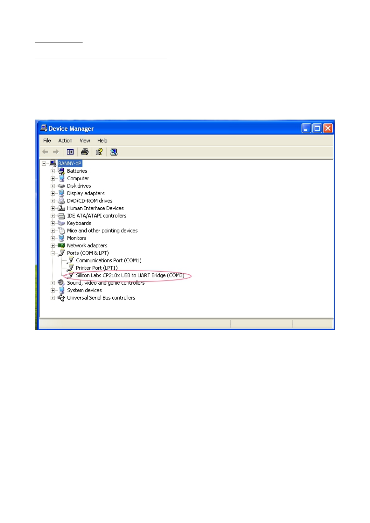
This application note describes the procedure to configure the USB port for HCS remote programming application.
HCS remote programmable power supply with USB can connected to PC through USB cable.
USB to serial bridge design i s used . When connected to PC, it will be converted as COM port shown in the following
picture. e.g. COM3
If the COM port does not come up, please check if the USB driver has been probably installed.
The USB driver comes with HCS software CD. Make sure the CD has been load to computer first.
Then it can program as stand COM port.
The default COM port setting;
baud rate : 9600
Data bits : 8 bit
stop bit : 1
Parity : None
The HCS then can be pro grammed for remote control etc. by the ASCII commands via the COM3.
All the command sets are given in the user manual of the po we r supply.
Rev.5 5/2017 7673-3300-0015
 Loading...