

Page 1

GAS-FLAMED ROTISSERIE OVEN
MODEL
MODEL HGFR
HGFR ML-132078 Natural Gas
ML-132079 Propane Gas
701 S. RIDGE AVENUE
TROY, OHIO 45374-0001
937 332-3000
www.hobartcorp.com
FORM 35504 Rev. A (Mar. 2005)
Page 2

IMPORTANT FOR YOUR SAFETY
THIS MANUAL HAS BEEN PREPARED FOR PERSONNEL QUALIFIED TO INSTALL GAS
EQUIPMENT, WHO SHOULD PERFORM THE INITIAL FIELD START-UP AND
ADJUSTMENTS OF THE EQUIPMENT COVERED BY THIS MANUAL.
POST IN A PROMINENT LOCATION THE INSTRUCTIONS TO BE FOLLOWED IN THE
EVENT THE SMELL OF GAS IS DETECTED. THIS INFORMATION CAN BE OBTAINED
FROM THE LOCAL GAS SUPPLIER.
IMPORTANT
IN THE EVENT A GAS ODOR IS DETECTED, SHUT DOWN
UNITS AT MAIN SHUTOFF VALVE AND CONTACT THE LOCAL
GAS COMPANY OR GAS SUPPLIER FOR SERVICE.
FOR YOUR SAFETY
DO NOT STORE OR USE GASOLINE OR OTHER FLAMMABLE
VAPORS OR LIQUIDS IN THE VICINITY OF THIS OR ANY
OTHER APPLIANCE.
WARNING: IMPROPER INSTALLATION, ADJUSTMENT,
ALTERATION, SERVICE OR MAINTENANCE CAN CAUSE
PROPERTY DAMAGE, INJURY OR DEATH. READ THE
INSTALLATION, OPERATING AND MAINTENANCE
INSTRUCTIONS THOROUGHLY BEFORE INSTALLING OR
SERVICING THIS EQUIPMENT.
IN THE EVENT OF A POWER FAILURE, DO NOT ATTEMPT TO
OPERATE THIS DEVICE.
© HOBART CORPORATION 2002, 2005
– 2 –
Page 3

CONTENTS
GENERAL . . . . . . . . . . . . . . . . . . . . . . . . . . . . . . . . . . . . . . . . . . . . . . . . . . . . . . . . 4
INSTALLATION . . . . . . . . . . . . . . . . . . . . . . . . . . . . . . . . . . . . . . . . . . . . . . . . . . . . . . . 5
Location . . . . . . . . . . . . . . . . . . . . . . . . . . . . . . . . . . . . . . . . . . . . . . . . . . . . . . . 5
Installation Codes and Standards . . . . . . . . . . . . . . . . . . . . . . . . . . . . . . . . . . . 5
Venting Requirements . . . . . . . . . . . . . . . . . . . . . . . . . . . . . . . . . . . . . . . . . . . . 5
Unpacking . . . . . . . . . . . . . . . . . . . . . . . . . . . . . . . . . . . . . . . . . . . . . . . . . . . . . . 5
Assembly . . . . . . . . . . . . . . . . . . . . . . . . . . . . . . . . . . . . . . . . . . . . . . . . . . . . . . 6
Leveling. . . . . . . . . . . . . . . . . . . . . . . . . . . . . . . . . . . . . . . . . . . . . . . . . . . . . . . . 7
Tether Connection . . . . . . . . . . . . . . . . . . . . . . . . . . . . . . . . . . . . . . . . . . . . . . . 7
Plumbing Connection . . . . . . . . . . . . . . . . . . . . . . . . . . . . . . . . . . . . . . . . . . . . . 7
Electrical Connection . . . . . . . . . . . . . . . . . . . . . . . . . . . . . . . . . . . . . . . . . . . . . 8
Gas Connection . . . . . . . . . . . . . . . . . . . . . . . . . . . . . . . . . . . . . . . . . . . . . . . . . 8
Before First Use . . . . . . . . . . . . . . . . . . . . . . . . . . . . . . . . . . . . . . . . . . . . . . . . . 8
OPERATION . . . . . . . . . . . . . . . . . . . . . . . . . . . . . . . . . . . . . . . . . . . . . . . . . . . . . . . . 9
Set Up Rotisserie Oven . . . . . . . . . . . . . . . . . . . . . . . . . . . . . . . . . . . . . . . . . 10
Preheating. . . . . . . . . . . . . . . . . . . . . . . . . . . . . . . . . . . . . . . . . . . . . . . . . . . . 11
Preparing Chickens for Roasting. . . . . . . . . . . . . . . . . . . . . . . . . . . . . . . . . . 11
Loading . . . . . . . . . . . . . . . . . . . . . . . . . . . . . . . . . . . . . . . . . . . . . . . . . . . . . . 13
Manual Cooking . . . . . . . . . . . . . . . . . . . . . . . . . . . . . . . . . . . . . . . . . . . . . . . . 14
Holding . . . . . . . . . . . . . . . . . . . . . . . . . . . . . . . . . . . . . . . . . . . . . . . . . . . . . . 14
Programmed Cooking . . . . . . . . . . . . . . . . . . . . . . . . . . . . . . . . . . . . . . . . . . 15
Holding . . . . . . . . . . . . . . . . . . . . . . . . . . . . . . . . . . . . . . . . . . . . . . . . . . . . . . 15
Preprogrammed Recipes . . . . . . . . . . . . . . . . . . . . . . . . . . . . . . . . . . . . . . . . 16
Modifying a Preprogrammed Recipe. . . . . . . . . . . . . . . . . . . . . . . . . . . . . . . . 17
Unloading . . . . . . . . . . . . . . . . . . . . . . . . . . . . . . . . . . . . . . . . . . . . . . . . . . . . 18
Shutdown . . . . . . . . . . . . . . . . . . . . . . . . . . . . . . . . . . . . . . . . . . . . . . . . . . . . 18
Cleaning . . . . . . . . . . . . . . . . . . . . . . . . . . . . . . . . . . . . . . . . . . . . . . . . . . . . . 18
MAINTENANCE . . . . . . . . . . . . . . . . . . . . . . . . . . . . . . . . . . . . . . . . . . . . . . . . . . . . . 21
Monthly . . . . . . . . . . . . . . . . . . . . . . . . . . . . . . . . . . . . . . . . . . . . . . . . . . . . . . 21
Annually . . . . . . . . . . . . . . . . . . . . . . . . . . . . . . . . . . . . . . . . . . . . . . . . . . . . . 21
TROUBLESHOOTING . . . . . . . . . . . . . . . . . . . . . . . . . . . . . . . . . . . . . . . . . . . . . . . . 22
Service and Parts Information . . . . . . . . . . . . . . . . . . . . . . . . . . . . . . . . . . . . 22
– 3 –
Page 4

Installation, Operation and Care of
HGFR GAS-FLAMED ROTISSERIE OVEN
SAVE THESE INSTRUCTIONS
GENERAL
The model HGFR Series Gas-Flamed Rotisserie Oven features stainless steel interior and exterior for
ease of cleaning. Infrared ceramic gas burners efficiently roast the product. The rotisserie rotates the
product on spits as it revolves around the rotisserie oven. The product roasts evenly and self-bastes
throughout the cooking process. The drip pan's water bath system in the bottom of the rotisserie oven
adds moisture during roasting, catches the fat drippings (reducing the chance of fire) and facilitates
easy cleanup. This rotisserie oven has been exclusively designed to grill meat products. A see-through
window option is available.
GAS AND ELECTRICAL DATA
Type Manifold Supply Pressure Volts / Hertz / Phase Oven Minimum Circuit Ampacity
of BTU/hr Pressure Amps Maximum Protective Device
Gas Min. Max. AMPS
Natural 116,000 5.5"W.C. 7"W.C. 14"W.C. 120 / 60 / 1 3 15
(1.37 kPa) (1.74 kPa) (3.49 kPa)
Propane 120,000 11"W.C. 12"W.C. 14"W.C. 120 / 60 / 1 3 15
(2.74 kPa) (2.98 kPa) (3.49 kPa)
– 4 –
Page 5

INSTALLATION
Prior to installation, verify that the electrical service and gas supply (natural or propane) agree with the
specifications on the machine data plate located on the right side of the rotisserie oven.
LOCATION
WARNING: THE ROTISSERIE OVEN SHOULD NOT BE ACCESSIBLE TO THE CUSTOMER; HOT
GLASS AND PARTS CAN CAUSE BURNS.
The equipment area must be kept free and clear of combustibles. Maintain clearances from combustible
and noncombustible construction of 3" (
the optional glass back, clearance from combustible and noncombustible construction must be 3"
(
7.6 cm) at side and 15" (38.1 cm) from the rear of the rotisserie oven. The installation location must allow
adequate clearances for servicing: 18" (
Adequate clearances must also allow for proper operation of the doors. The rotisserie oven is suitable
for installation on combustible floors. The rotisserie oven must be level for the rotor to operate properly.
The rotisserie oven must be installed so that the flow of combustion and ventilation air will not be
obstructed. The bottom of the rotisserie oven must be kept clear so that the air openings into the
combustion chamber are not obstructed. Make sure there is an adequate supply of air in the room to
allow for that required for combustion of gas at the rotisserie oven burners.
7.6 cm) at the sides and rear. If rotisserie oven is equipped with
46 cm) is recommended when used with leveling feet.
INSTALLATION CODES AND STANDARDS
In the United States, the gas rotisserie oven must be installed in accordance with: 1) State and local
codes; 2) National Fuel Gas Code, ANSI-Z223.1 (latest edition), available from American Gas
Association, 1515 Wilson Boulevard, Arlington, VA 22209; 3) ANSI/NFPA 96,
Cooking Equipment
(latest edition), available from National Fire Protection Association, Batterymarch
Vapor Removal from
Park, Quincy, MA 02269; and 4) National Electrical Code, ANSI/NFPA-70 (latest edition).
In Canada, the gas rotisserie oven must be installed in accordance with: 1) Local codes; 2) CAN/
CSA149.1,
Natural Gas and Propane Installation Code
(latest edition); and 3) Canadian Electrical
Code, Part 1, CSA Standard C22.1 (latest edition).
VENTING REQUIREMENTS
Refer to
Vapor Removal from Cooking Equipment
, NFPA 96 (latest edition). The rotisserie oven cannot
be directly vented to a gas flue or exhaust. It should be operated under an exhaust hood that extends
at least 6" (
15.2 cm) beyond the rotisserie oven's sides. Clearance above the rotisserie oven flue should
allow the products of combustion to escape without interfering with heat circulation in the rotisserie
oven.
UNPACKING
Immediately after unpacking, check the rotisserie oven for possible shipping damage. If the rotisserie
is found to be damaged, save the packaging material and contact the carrier within 15 days of delivery.
Remove all vinyl paper from the stainless steel surfaces on the interior and exterior of the rotisserie
oven. Remove all tape from the glass and metal surfaces.
– 5 –
Page 6
ASSEMBLY
PL-41689-1
CERAMIC LOGS
IGNITOR BOX
Carefully remove and inspect all loose parts packed with the rotisserie oven, including the following:
Overflow Tube (1) Skim Tube (1) Ceramic Logs (4)
Removable Rear Panel (1) Door Handle Knobs (2) Wire Rack (1)
Unwrap foot pedal switch and place on floor.
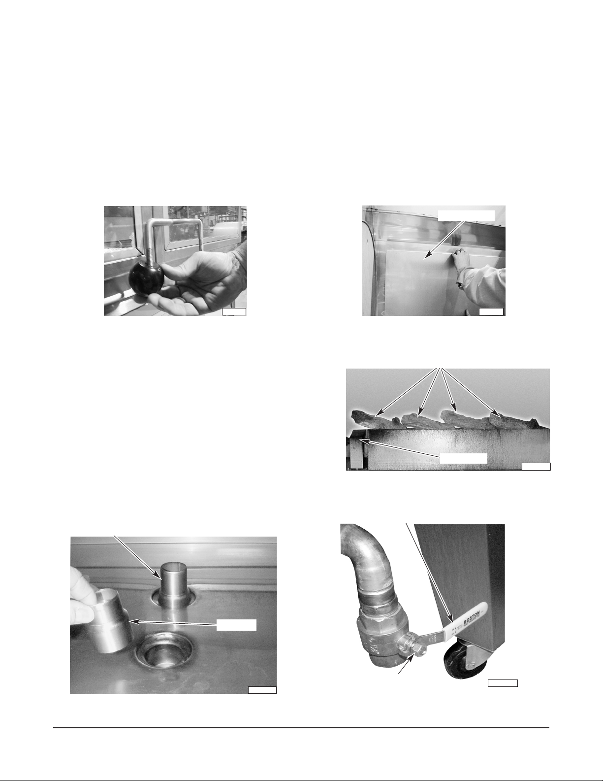
Screw the door handle knobs onto the door handle rods and tighten them firmly (Fig. 1).
Hang the upper edge of the removable hanging panel from the hanger strip on the rear wall inside the
rotisserie (Fig. 2). Panel must be flat against rear rotisserie oven cavity wall.
HANGING PANEL
PL-41706 PL-41707
Fig. 1 Fig. 2
Place ceramic logs on log rack. Place logs beginning on
the left side with the right side of each log angled down
(Fig. 3). Place the left ceramic log over the ignitor box to
prevent fat from clogging the burner holes.
Remove the wire rack and install the overflow and skim
tubes, wide side down, in the drains at the bottom of the
rotisserie (Fig. 4); placement is interchangeable. Replace
the wire rack.
Remove the drain handle from its shipping location on the
drain valve and install it properly on the drain valve stem
(Fig. 5).
OVERFLOW TUBE
SKIM TUBE
Fig. 3
DRAIN VALVE HANDLE
DRAIN VALVE STEM
PL-41658-1
Fig. 4 Fig. 5
– 6 –
PL-41659-1
Page 7
LEVELING
If the rotisserie oven is equipped with casters (standard), move
the rotisserie oven to its final installed position and lock the front
casters; back casters are nonlocking. Casters are nonadjustable;
therefore, the floor must be level to avoid experiencing cooking
problems.
If the rotisserie oven is equipped with adjustable feet (optional),
move the rotisserie oven to its final installed position. Place a
spirit level on top of the rotisserie oven and turn the adjustable feet
in or out to level the rotisserie oven front to back and side to side.
TETHER CONNECTION
HOLE
FOR
TETHER
When equipped with casters, the gas connection must be made
with a connector that complies with the Standard for Connectors
for Movable Gas Appliances, ANSI Z21.69 (latest edition) or
Connectors for Moveable Gas Appliances, (CAN/CGA-6.16) and
must be made with a quick-disconnect device that complies with
the Standard for Quick-Disconnect Devices for Use With Gas
Fuel, ANSI Z21.41 (latest edition) or Quick-Disconnect Devices
for Use With Gas Fuel (CANI-6.9). Tether the rotisserie oven
using the hole provided on the left side of machine next to the gas
connection (Fig. 6).
If disconnection of the tether is necessary, turn off the gas and
water supplies before disconnecting. After returning the rotisserie
oven to its original position, reconnect the tether before turning the
gas and water supplies back on.
PLUMBING CONNECTION
WARNING: PLUMBING CONNECTIONS MUST COMPLY WITH
APPLICABLE SANITARY, SAFETY AND PLUMBING CODES.
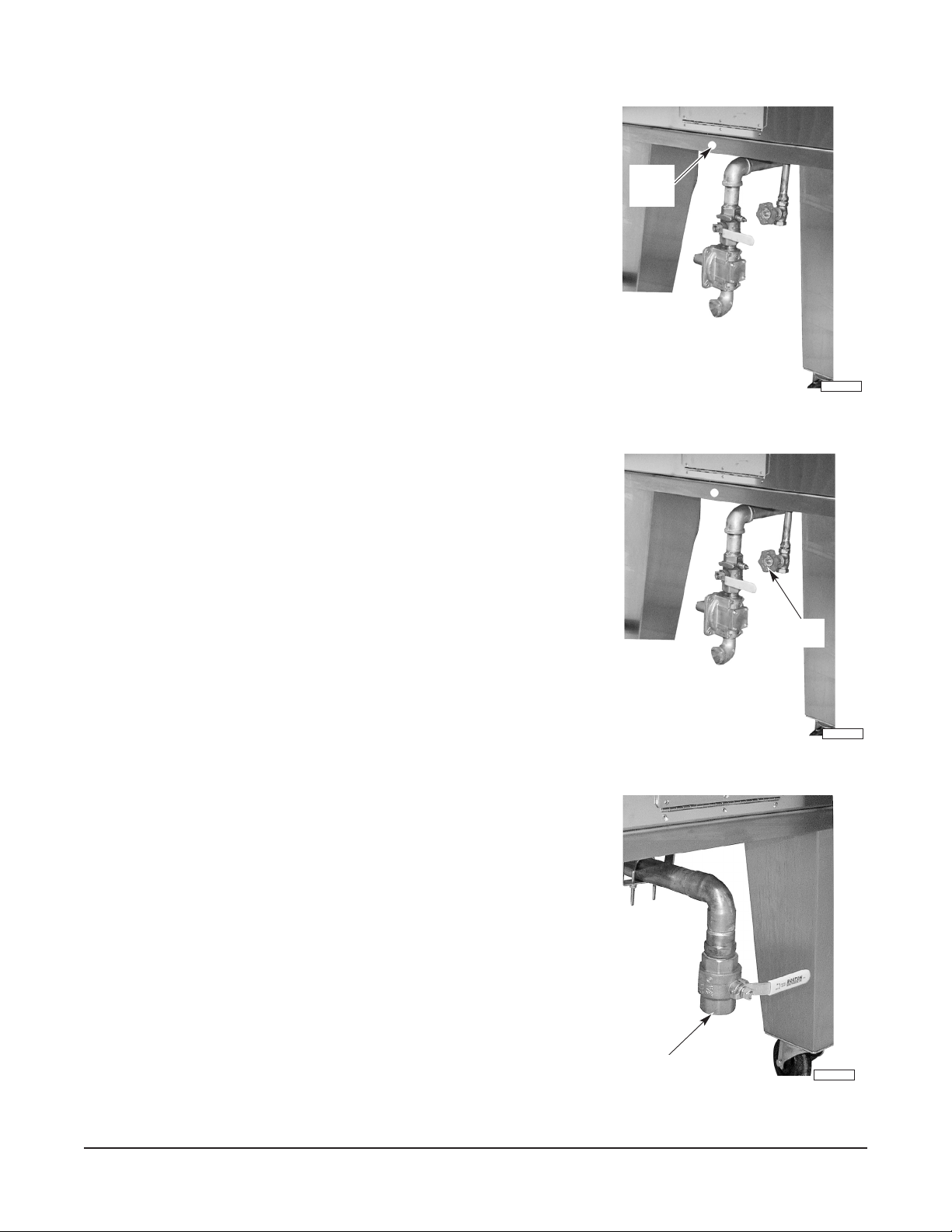
Water Supply Connection (Fig. 7)
The rotisserie oven is equipped with a water bath system in the
bottom of the rotisserie oven. It can be connected to the potable
water supply at the
1
/2" NPT (1.3 cm) supply valve connection. A
flexible connection is recommended to allow for rotisserie oven
movement.
Fig. 6
Fig. 7
WATER
VALV E
PL-41656-1
PL-41690-1
Drain Connection (Fig 8)
For optional permanent connection, a 1
1
/2" NPT (3.8 cm) drain
connection is also provided. If connecting to a drain, make sure
the drain is connected to a grease trap.
– 7 –
DRAIN CONNECTION
PL-41655-1
Fig. 8
Page 8
ELECTRICAL CONNECTION
WARNING: ELECTRICAL AND GROUNDING CONNECTIONS MUST COMPLY WITH THE
APPLICABLE PORTIONS OF THE NATIONAL ELECTRICAL CODE AND/OR OTHER LOCAL
ELECTRICAL CODES.
WARNING: THIS MACHINE IS PROVIDED WITH A THREE-PRONG GROUNDING PLUG. THE
OUTLET TO WHICH THIS PLUG IS CONNECTED MUST BE PROPERLY GROUNDED. IF THE
RECEPTACLE IS NOT THE PROPER GROUNDING TYPE, CONTACT AN ELECTRICIAN.
Do not plug in until after the gas connection has been made and checked for leaks.
GAS CONNECTION
All gas supply connections and any pipe joint compound must
be resistant to the action of propane gas. Codes require that
a gas shutoff valve be installed in the gas line ahead of the
rotisserie oven; use the valve provided. A gas pressure
regulator is supplied with the rotisserie oven.
Connect the rotisserie oven to a 1" (
2.5 cm) gas supply line
(Fig. 9). Make sure the pipes are clean and free of obstructions,
dirt and piping compound. Connecting the rotisserie oven to
a smaller gas supply line is not recommended because this
will reduce the effectiveness of the burners or cause improper
operation.
WARNING: PRIOR TO STARTING, CHECK ALL JOINTS IN
THE GAS SUPPLY LINE FOR LEAKS. USE SOAP AND
WATER SOLUTION. DO NOT USE AN OPEN FLAME.
For natural gas, adjust the gas pressure regulator to provide a manifold pressure of 5.5" W.C. (
The minimum supply pressure for natural gas is 7" W.C. (
1.74 kPa); maximum is 14" W.C. (3.49 kPa).
For propane, adjust the gas pressure regulator to provide a manifold pressure of 11" W.C. (
The minimum supply pressure for propane is 12" W.C. (
2.98kPa); the maximum is 14" W.C. (3.49kPa).
GAS
PRESSURE
REGULATOR
GAS
CONNECTION
Fig. 9
PL-41691-1
1.37 kPa).
2.74kPa).
The rotisserie oven and its individual shutoff valve must be disconnected from the gas supply piping
system during any pressure testing of that system at test pressures in excess of
1
/2 psi (3.45 kPa).
The rotisserie oven must be isolated from the gas supply piping system by closing its individual manual
shutoff valve during any pressure testing of the gas supply piping system at test pressures equal to or
less than 1/2 psi (3.45 kPa).
BEFORE FIRST USE
WARNING: DISCONNECT ELECTRICAL POWER BEFORE CLEANING.
Clean and sanitize the rotisserie oven inside and outside with warm, soapy water. Rinse thoroughly
and wipe dry with a soft, clean cloth. Clean all spits and accessories with warm, soapy water; rinse
thoroughly and wipe dry.
Care must be taken to ensure the burners and ignitors do not get wet. Refer to Cleaning, pages 18
through 20.
Before using the rotisserie oven for the first time, it must be "burned in" to release any odors that might
result from heating the new surfaces in the rotisserie oven. Remove all vinyl paper and operate the
rotisserie oven empty at the maximum temperature for 1 hour. Smoke with an unpleasant odor normally
will be given off during this burn-in period.
– 8 –
Page 9

OPERATION
WARNING: HOT GLASS, GREASE AND PARTS CAN CAUSE BURNS. USE CARE WHEN
OPERATING, CLEANING AND SERVICING THE ROTISSERIE.
CONTROL PANEL
FOOT PEDAL SWITCH
Fig. 10
Foot switch (Fig. 10) — Press/release to stop/start rotor when Motor switch is on.
– 9 –
Page 10

SET UP ROTISSERIE OVEN
• Cover center shaft in the rotisserie oven with aluminum foil.
CAUTION: Do not spray gas burners, ignitors or lights with nonstick product.
• Spray noncooking components such as the interior walls, drum surfaces and wire rack with a
nonstick product (Figs. 11, 12).
• Spray spits and accessories with a nonstick product.
DO SPRAY
DO NOT SPRAY
PL-41709-1
Fig. 11 Fig. 12
DRAIN VALVE HANDLE
WATER
GAS VALVE
HANDLE
PL-41699-1
VALV E
PL-41693-1
Fig. 13 Fig. 14
• Close drain valve handle (Fig. 13).
– For systems plumbed to water line, turn water valve knob (Fig. 14) on until 1" of water is in
the drip pan, then turn water valve knob off.
– For systems not plumbed to water line, manually add 1" of water to the drip pan.
• Open main gas valve (Fig. 14).
– 10 –
Page 11

PREHEATING
• Controller displays rdy .
• Turn Lights switch on (Fig. 15).
• Turn Motor switch on (Fig. 15).
• Turn Show Burner switch on (Fig. 15).
• Check to see that Show Burner is lit.
• If Burner does not ignite, turn Show Burner switch off then on again.
• Preheat rotisserie oven for 15 – 20 minutes with show burner.
HOBART
Burners
Show Top Front Top Rear
Motor Lights Temperature
rdy
Temperature - Time Controller
COOK COOK
TEMP TIME
HOLD START
TEMP STOP
Fig. 15
READ
SAVE
PREPARING CHICKENS FOR ROASTING
The rotisserie oven is not designed to roast frozen foods. Use only fresh or properly thawed product.
• Bring chickens from cooler.
• Check temperature of chicken; temperature should be between 37°F and 42°F. Insert approved
popper into chicken breast. Popper will pop up when chicken is done (Fig. 16).
• Wrap the end of approved tie around the legs of chicken. Pull up and crisscross over back
(Fig. 17).
POPPER
PL-41694-1
Fig. 16 Fig. 17
– 11 –
PL-41695-1
Page 12

• Bring tie to front, holding the wings to the side of the chicken (Fig. 18).
• Insert angle spit (V) neck first (Fig. 19).
PL-41696
PL-41697
Fig. 18 Fig. 19
• The flat side of spit must be parallel with breast bone (Fig. 20).
• Make sure that the legs and thighs are on the same side as breasts (Fig. 21).
PL-41698
Fig. 20 Fig. 21
• The angle spit (Fig. 22) holds five average size chickens weighing approximately 3.3 lbs.
Continue loading angle spits until all spits are completed.
• Install the optional spit locks (if desired). Place spit lock at end of spit and tighten with spit lock
tool (Fig. 23).
POINTED END
SPIT
LOCK
TOOL
CHICKEN LEGS
TOWARD
POINTED END
PL-56359
CHICKEN NECK
AGAINST
ROUND FLANGE
SPIT
LOCK
DRIVE END
Fig. 22 Fig. 23
– 12 –
PL-41710-1
Page 13

LOADING
• Insert pointed end of the angle spits into left side of rotor, facing the unit (Fig. 24).
CAUTION: Do not jam angle spit into the square hub.
• Insert square end of the angle spit in the square hub on the right side of the rotor (Fig. 25).
PL-41700 PL-41701
Fig. 24 Fig. 25
• Ensure round end of the angle spit drops down so the square end, on the right side, is properly
held in place and fully engaged. Repeat for all angle spits (Fig. 26).
NOTE: Stagger loading. Angle spits must be loaded on alternate positions of the rotor until all positions
are loaded. When cooking a partial batch with less than seven or eight angle spits, the angle spits must
be staggered on the rotor.
• Use the foot pedal to stop / start rotor rotation (Fig. 27). Load every other spit position until all
spits are in position: For example, load the first position, skip the second, load the third, skip
the forth, etc.
• Close the door.
PL-41702
Fig. 26 Fig. 27
PL-41703
– 13 –
Page 14

MANUAL COOKING
In manual mode Cook Time, Cook Temp and Hold Temp settings are saved in short-term memory only
and should be verified each time a manual process begins. Controller cycles top burners on and off.
When cooking partial loads or when cooking special glazes, cook with one burner on or with a lower
Cook Temp setting.
HOBART
Burners
Show Top Front Top Rear
Motor Lights Temperature
rdy
Temperature - Time Controller
COOK COOK
TEMP TIME
HOLD START
TEMP STOP
Fig. 28
READ
SAVE
• Controller displays rdy .
• To set Cook Temp, press and hold while using the up or down keys to adjust the Cook
COOK
TEMP
Temp setting (100°F to 600°F). The recommended cook temp is 575°F for typical full load.
COOK
• To set the Cook Time, press and hold while using the up or down keys to adjust the Cook
TIME
Time setting (0:01 to 4:15). Recommended cook time is 1:15 to 1:30 for typical full load.
• To set Hold Temp, press and hold while using the up or down keys to adjust the Hold Temp
HOLD
TEMP
setting (150°F to 300°F). Do not use Hold Temp settings from 100 to 149°F. A Hold Temp
setting of 200°F is recommended.
• To start the manual cooking process, press .
START
STOP
• The display alternates between the Cook Temp setting and the remaining Cook Time preceded
by a c, for example: 575
° c1:30 . The c indicates that the cook cycle has started and the timer
is counting down.
• Press the Temperature switch on (Fig. 28).
• Turn Top Front and Top Rear Burner switches on.
• Check the burners in the top of the cavity (Fig. 29)
to ensure burners are lit and beginning to glow red.
• If one or both top burners do not ignite, turn burner
TOP BURNERS GLOW RED
switch(es) off and on again.
HOLDING
• When cook time expires and the controller beeps, press .
NOTE: Pressing the button when in Hold Mode returns oven to cook cycle for an additional
COOK
TIME
HOLD
TEMP
Fig. 29
5 minutes.
• The display alternates between the Hold Temp setting and the elapsed hold time preceded by
an h, for example: 200
• To stop a Hold cycle, press .
° h0:01 . The h indicates that the hold cycle has started.
START
STOP
• Controller displays rdy .
– 14 –
PL-41711-1
Page 15

PROGRAMMED COOKING
In programmed mode, preprogrammed recipes stored in long-term memory are used. Controller
cycles top burners on and off. When cooking partial loads or when cooking special glazes, cook with
one burner on or with a lower Cook Temp setting.
HOBART
Burners
Show Top Front Top Rear
Motor Lights Temperature
rdy
Temperature - Time Controller
COOK COOK
TEMP TIME
HOLD START
TEMP STOP
Fig. 30
READ
SAVE
• Controller displays rdy .
• Press . The last operated program displays, for example: r01 .
READ
• Press the up or down keys until the desired recipe number is displayed, for example: r03 .
• To start the selected cooking process, press .
START
STOP
• The display alternates between the program in use, the selected program's Cook Temp setting
and the remaining Cook Time preceded by a c, for example: r03 575
° c1:30 . The c in the
display indicates that the cook cycle has started and the timer has begun to count down.
• Press the Temperature switch on (Fig. 30).
• Turn Top Front and Top Rear Burner switches on.
• Check the burners in the top of the cavity (Fig. 31)
to ensure burners are lit and beginning to glow red.
• If one or both top burners do not ignite, turn burner
switch(es) off and on again.
TOP BURNERS GLOW RED
HOLDING
• When the selected recipe's cook time expires and controller beeps, press .
NOTE: Pressing the button when in Hold Mode returns oven to cook cycle for an additional
COOK
TIME
Fig. 31
HOLD
TEMP
5 minutes.
• The display alternates between the Hold Temp setting and the elapsed Hold Time preceded by
an h, for example: 200
• To stop a Hold cycle, press and hold .
° h0:01 . The h indicates that the Hold cycle has started.
START
STOP
• Controller displays rdy .
PL-41711-1
– 15 –
Page 16

PREPROGRAMMED RECIPES
Twelve recipes, shown below, are preprogrammed at the factory. The table provides an extra space for
each recipe so you can pencil in your own settings if you choose to reprogram a recipe.
Recipe # Cook Temp Cook Time Hold Temp
r01 575°F1 hr 200°F
r01
r02 575°F1 hr 15 min 200°F
r02
r03 575°F1 hr 30 min 200°F
r03
r04 575°F1 hr 45 min 200°F
r04
r05 575°F2 hr 200°F
r05
r06 475°F1 hr 200°F
r06
r07 475°F1 hr 15 min 200°F
r07
r08 475°F1 hr 30 min 200°F
r08
r09 475°F1 hr 45 min 200°F
r09
r10 475°F2 hr 200°F
r10
r11 500°F1 hr 30 min 200°F
r11
r12 575°F 15 min 200°F
r12
– 16 –
Page 17

MODIFYING A PREPROGRAMMED RECIPE
HOBART
Burners
Show Top Front Top Rear
Motor Lights Temperature
rdy
Temperature - Time Controller
COOK COOK
TEMP TIME
HOLD START
TEMP STOP
Fig. 32
READ
SAVE
Selecting the Recipe
• Controller displays rdy .
• Press . The last operated program displays, for example: r01 .
READ
• Press the up or down keys until the desired recipe number is displayed. For example: r03 .
• Press and together to enter program mode.
COOK
TEMP
COOK
TIME
• Controller displays prog .
Modifying the Recipe
• Press and hold the Cook Time, Cook Temp or Hold Temp button while using the up or down
arrow keys to adjust the setting. For example:
COOK
TEMP
COOK
TIME
HOLD
TEMP
600
1:20
210
°
°
Saving the Recipe
• Press .
SAVE
• Controller displays rdy .
• Make a record of any modified recipe settings by noting them on the recipe list on page 16.
– 17 –
Page 18

UNLOADING
WARNING: PRODUCT WILL BE HOT WHEN UNLOADING ACCESSORIES. USE CARE WHEN
UNLOADING THE ROTISSERIE OVEN.
• Stop hold cycle, open door and begin unloading.
• Step on and hold down the foot switch to stop
rotor.
• Use a thermometer to check product for doneness
(popper can also be an indicator of doneness).
Refer to Manual Cooking, above, to set additional
time if needed.
• Use insulated gloves and remove the angle Vspits (Fig. 33).
• Release foot switch.
• Place product in containers and into warming
cabinet immediately.
Fig. 33
SHUTDOWN
At end of day or in case of prolonged power outage:
• Turn all switches off;
• Shut off gas and disconnect electrical power.
CLEANING
WARNING: HOT GLASS, GREASE AND PARTS, INCLUDING CERAMIC LOGS, CAN CAUSE
BURNS. USE CARE WHEN CLEANING AND SERVICING THE ROTISSERIE OVEN.
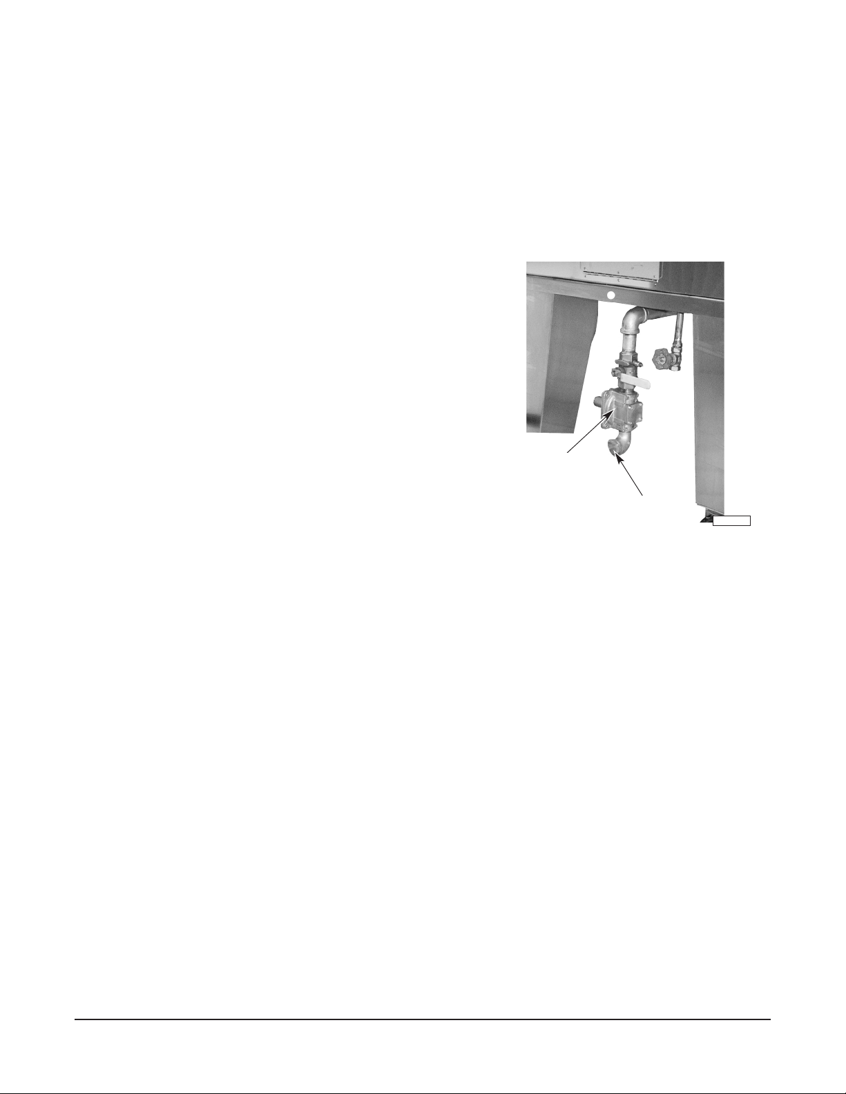
After Each Cooking Cycle
DRAIN
VALV E
HANDLE
WATER
VALV E
BUCKET
PL-41705-1
Fig. 34 Fig. 35
PL-41690-1
• Place a bucket under drain connection (Fig. 34) unless connected to a drain and grease trap.
• Open drain valve.
• If using a bucket, it may need to be emptied several times. Do not let the bucket overflow, close
drain valve when bucket is half full and discard water.
– 18 –
Page 19

• Add water to the drip pan until the grease has flowed into the skim tube and down through the
drain connection.
– For systems plumbed to water line, turn water valve knob on until grease is removed from
the drip pan, then turn water valve off (Fig. 35).
– For systems not plumbed to water line, manually add water until grease is removed from the
drip pan.
• Close drain valve.
• Remove bucket, if used, and dispose of greasy water.
• Add a minimum of 1" of water, if necessary, to drip pan and continue cooking.
End of Day
WARNING: DISCONNECT ELECTRICAL POWER BEFORE CLEANING.
CAUTION: Do not use oven cleaners or high-pressure hoses to clean rotisserie oven.
• Open hinged doors and allow rotisserie oven to cool. Center shaft retains heat. Allow to cool.
• Remove aluminum foil from center shaft.
• Remove wire rack, overflow and skim tube and allow them to soak 15 to 20 minutes in a sink
with warm, soapy water or clean in a commercial dishwasher.
• Place bucket under drain connection unless connected to a drain and grease trap.
• Open drain valve and drain water from drip pan.
• The bucket will have to be emptied several times. Do not let the bucket overflow, close drain
valve when bucket is half full and discard water.
• Close drain valve. Empty bucket, if used, and place back under drain connection.
• Refill drip pan with warm, soapy water.
CAUTION: Do not spray cleaners on ceramic logs or ignitor box.
CAUTION: Do not spray or wipe down top burners.
• Wipe down the interior of the rotisserie oven and drums with soapy water from the drip pan using
a sponge or soft cloth. Clean the square holes of the drum, located on the right side of the
rotisserie oven.
CAUTION: Do not use abrasives or razor blades on the glass as they will scratch the surface,
causing it to break without notice.
• Clean the hinged glass doors with warm, soapy water, rinse and dry, or use a commercial glass
cleaner. Do not use a scouring pad. Damage to the inside of the door will result.
• Clean door handles with warm, soapy water and a clean, soft cloth.
• If the rotisserie oven is equipped with the see-through option, remove the glass panels and
clean them with warm, soapy water, rinse and dry, or use a commercial glass cleaner. Do not
use scouring pad. Damage to glass will result. Next, wipe down glass track and replace glass
panels.
– 19 –
Page 20

CAUTION: Excessive water and harsh cleaners will damage control panel.
• Clean the control panel with a sponge or clean, soft cloth.
• Clean the exterior of the rotisserie oven with warm, soapy water and a soft cloth or sponge.
Rinse thoroughly and wipe dry with a soft, clean cloth.
• Open drain valve and drain soapy water from drip pan into empty bucket. Rinse with clean water
and dry drip pan with a soft cloth.
• The bucket may have to be emptied several times.
Do not let the bucket overflow, close drain valve
when bucket is half full and discard water.
LOG RACK
• Close drain valve.
• Place overflow tube, skim tube and wire rack into
rotisserie oven.
• Clean and sanitize all accessories.
PL-41708-1
Fig. 36
Weekly
WARNING: DISCONNECT ELECTRICAL POWER
BEFORE CLEANING.
HANGING PANEL
• Allow rotisserie oven to cool. Center shaft retains
heat. Allow to cool.
• Carefully remove ceramic logs from log rack.
• Lift log rack (Fig. 36) up and out of rotisserie oven
cavity and clean in a sink with warm, soapy water or
degreaser.
PL-41707
• Lift out hanging panel (Fig. 37) in rear of rotisserie
oven and clean in a sink with warm, soapy water or
Fig. 37
degreaser.
• Wipe angled shelf under gas line, in rear of rotisserie oven, with soapy water using a sponge
or soft cloth.
• Place hanging panel into rotisserie oven. Panel must be flat against rear rotisserie oven cavity
wall.
• Place log rack into rotisserie oven.
CERAMIC LOGS
• Place ceramic logs on log rack. Place logs beginning
on the left side with the right side of each log angled
down (Fig. 38). Place the left ceramic log over the
ignitor box to prevent fat from clogging the burner
holes.
PL-41657-1
– 20 –
Fig. 38
Page 21

MAINTENANCE
WARNING: DISCONNECT ELECTRICAL POWER SUPPLY BEFORE PERFORMING ANY
MAINTENANCE.
WARNING: HOT GLASS, GREASE AND PARTS CAN CAUSE BURNS. USE CARE WHEN
OPERATING, CLEANING AND SERVICING THE ROTISSERIE OVEN.
Light bulbs require replacement periodically. Replace with same size and type.
MONTHLY
To ensure the show burner is operating efficiently, remove ceramic logs and log holder and clean any
debris from the burner openings with a paper clip. Remove any debris, grease or carbon from the
surrounding area.
ANNUALLY
Check glass doors for scratches or chips. If found, replace doors immediately.
Annually check the flue, when cool, to be sure it is free of obstructions.
Visually inspect double-rotation system for proper operation.
– 21 –
Page 22

TROUBLESHOOTING
Problem Possible Cause
Display not illuminated. Rotisserie oven not plugged in.
Top burner(s) will not 1. Temperature and burner switch(es) not on.
ignite. 2. Controller Cook Temp not set to 600°F (max.).
3. Main gas valve not open.
4. Pan or other object on top of rotisserie oven, restricting proper
airflow.
Show burner will not ignite 1. Main gas valve not open.
2. Motor switch not on.
3. Pan or other object on top of rotisserie oven, restricting proper
airflow.
Interior light(s) not working. 1. Light switch not on.
2. Light bulb(s) needs to be replaced.
Rotor will not turn. 1. Motor switch not on.
2. Foot pedal is jammed.
Top burner(s) goes out and 1. Controller Cook Temp not set to 600°F (max.).
stays out. 2. Hood air return blowing down onto rotisserie oven.
3. Main gas valve not completely open.
4. Pan or other object on top of rotisserie oven, restricting proper
airflow.
Machine is hard to move. 1. Tether still connected.
2. Front casters locked.
3. Machine on feet.
Product takes too long to cook. 1. Controller Cook Temp not set at 600°F (max.).
2. One or both top burners not ignited (and not glowing red).
Product cooks too quickly or 1. Controller Cook Temp set too high.
product is burnt on outside and 2. Both burners turned on (cook with one burner instead of two).
undercooked on inside.
Won't run a program. 1. Forgot to press .
Won't go into Hold mode. 1. Pressed instead of after cook cycle was completed.
START
STOP
Recipe did not get saved. 1. Forgot to press key.
READ
SAVE
HOLD
TEMP
SERVICE AND PARTS INFORMATION
Contact your local Hobart-authorized service office for any repairs or adjustments needed on this
equipment. Long-term service contracts are available on this and other Hobart products. To find your
nearest Hobart office call 1-888-4HOBART.
– 22 –
Page 23

NOTES
– 23 –
Page 24

NOTES
FORM 35504 Rev. A (Mar. 2005) PRINTED IN U.S.A.
– 24 –
 Loading...