

Page 1

HCM450 CUTTER MIXER
MODEL
HCM450 Cutter Mixer
HCM450 ML-134207
ML-134208
ML-134209
701 S. RIDGE AVENUE
TROY, OHIO 45374-0001
937 332-3000
www.hobartcorp.com
F-34772 Rev. E (May 2014)
Page 2

INSTALLATION, OPERATION AND CARE OF
Model HCM450 Cutter Mixer
SAVE THESE INSTRUCTIONS
GENERAL
The HCM450 Cutter Mixer cuts, mixes or blends foods quickly and effi ciently. A transparent lid allows
the operator to inspect the product during the mix-cut-blend process. The unit operates continuously,
momentarily or with a timer control which shuts off the machine automatically after the set time has elapsed.
The HCM450 bowl has a liquid capacity of 45 quarts.
The motor on HCM450 is rated 5 HP, 1140 RPM and has thermal overload protection. The motor is totally
enclosed with external fan cooling.
The cut mix shaft assembly is used for cutting meat products, vegetables, cheese, pastry, cake products
and some doughs that require both cutting and mixing.
The knead mix shaft assembly is used for applications where cutting is not required. It is especially good
for kneading yeast doughs.
The strainer basket may be used when cutting vegetables in water. After cutting, the strainer basket is
raised to allow the water to drain away from the food.
The bowl is locked in its vertical position during processing with the lock arm on HOLD. After processing,
when you move the lock arm from HOLD to TILT, the bowl can pivot to allow easy pouring.
When cutting certain products, a hand-operated mixing baffl e may be used to stir or move the product
into the knives. The mixing baffl e may be removed when it is not needed.
© HOBART, 1980, 1987, 2002, 2010
– 2 –
Page 3

UNPACKING
Immediately after unpacking, check for possible shipping damage. If the cutter mixer is found to be
damaged, save the packaging material and contact the carrier within 15 days of delivery.
Prior to installation, verify that the electrical service agrees with the specifi cations on the machine data
plate located on the frame behind the control box.
ASSEMBLY
Remove the cutter mixer from the skid and install rubber feet as follows: Apply a bead of silicon sealant
(not provided) around the edge of each leg. Insert a rubber foot onto each leg and fasten with bolts and
washers provided. Match the shape of the foot to conform to the shape of the leg. Two of each style are
included.
NOTE: Optional right and left casters (with rubber caster pads) are available for installation on the two
legs on the control panel side. Assemble with the bolts and washers provided for the rubber feet.
Place cutter mixer in the desired location.
ELECTRICAL CONNECTIONS
Electrical and grounding connections must comply with applicable portions of the
national electrical code and/or other local electrical codes.
Disconnect electrical power supply and place a tag at the disconnect switch,
indicating that the circuit is being worked on.
Machines are shipped from the factory with a 6-foot cord and plug. A mating receptacle is furnished with
the machine as standard equipment.
– 3 –
Page 4
ASSEMBLING BOWL SEAL AND ATTACHMENTS
Refer to the handbook accompanying the cutter mixer for recipe guidelines and advice regarding the
appropriate selection of attachments for the desired application.
Before installing bowl seal and attachments, be sure the power cord is unplugged.
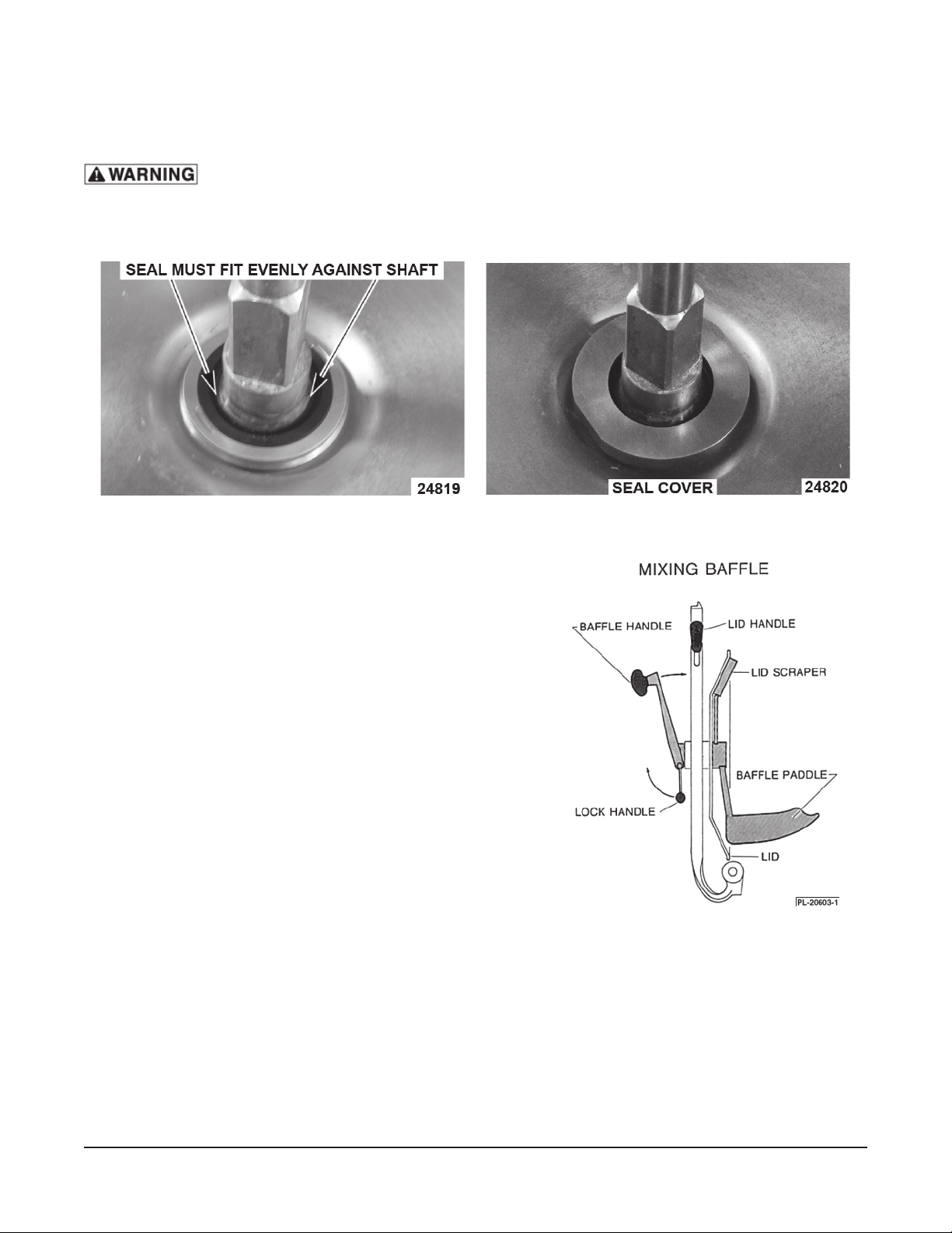
Bowl Seal: Insert rubber seal into the lower seal housing (Fig. 1). Press the seal down fully into housing.
Screw seal cover onto housing fi nger tight (Fig. 2).
Fig. 1 Fig. 2
Strainer Basket: If needed, insert basket in bowl over the
motor shaft.
NOTE: Never use strainer basket and mixing baffl e at the
same time.
Cut Mix Shaft Assembly or Knead Mix Shaft Assembly: Place
on motor shaft, seat square drive at base and tighten hand
knob by turning counterclockwise.
Lid Scraper: Insert on bar opposite mixing baffl e. Lid scraper
is used to clean the inside of the bowl cover.
Mixing Baffl e: Insert shaft of mixing baffl e into hole in the
center of the lid. With baffl e paddle down, hold baffl e handle
at an angle so lock handle hangs down and insert onto shaft.
Then tighten lock handle (Fig. 3).
Fig. 3
– 4 –
Page 5

OPERATION
Move bowl tilt handle to HOLD to lock bowl in vertical position (Fig. 4).
Close and latch the lid by grasping the lid handle with the left hand. Press lid handle down while turning
the latch until lid lock is engaged (Fig. 4).
CONTROLS (FIG. 4)
The Timer has three mode settings: Run, Jog or Timer.
RUN – Machine runs continuously after START is pushed until STOP is pressed.
JOG – Machine jogs momentarily while START is held down; the machine turns off
when you release START.
TIMER – After you set the time and push START, the machine will run for the
amount of time on the timer. After the set time has lapsed, the machine
automatically stops.
START – Turns the machine on.
STOP – Turns the machine off.
UNLOADING
Push the STOP switch. After the shaft has stopped, open the cover. NOTE: When the baffl e is not in
place, the lid opens a few inches upon release.
Remove the cut mix shaft assembly before emptying bowl. The knead mix shaft assembly may stay in
place while emptying the bowl.
Scrape lid (when necessary) before tipping bowl.
For products cut in water, lift out the strainer basket while the bowl is in the vertical position. Allow water
to strain through holes in bottom of strainer basket.
Move the bowl tilt handle to TILT.
The bowl may be tilted to any desired position, depending upon the type of product. Grasp the lid handle
and cautiously tilt the bowl by pulling toward you as the contents empty into a container.
After product has been removed, return bowl to vertical position. Return bowl tilt handle to HOLD position
and proceed to run another load or clean the machine.
– 5 –
Page 6

BAFFLE HANDLE
BAFFLE HANDLE
LOCK HANDLE
LID HANDLE
LID LATCH
START
STOP
LOCK HANDLE
CUT MIX SHAFT ASSEMBLY
BOWL TILT HANDLE
HAND KNOB
5-MINUTE TIMER
WITH JOG, RUN,
AND TIMED SETTINGS
KNEAD MIX SHAFT ASSEMBLY
LID SCRAPER
MIXING BAFFLE
STRAINER BASKET
PL-41654-1
Fig. 4
– 6 –
Page 7

CLEANING
Damage to the lid can result if it is exposed to certain chemicals. Do not use harsh abrasives,
such as powdered or liquid cleansers, steel wool or other abrasive pads; cleaners containing ammonia,
such as window sprays; cleaners containing chlorine, solvents, chemical adhesives; and highly caustic
chemicals, such as drain cleaners or commercial dishwasher detergents.
PREWASH
Before disassembling, put 1gallon of warm water and 1or 2 tablespoons of a mild liquid household
dishwashing detergent, such as Joy, Ivory or Palmolive Green in the bowl. Close and latch the lid. Turn
the timer to JOG and run for three bursts of 3 seconds each so the solution is thoroughly mixed.
WASH BOWL AND COMPONENTS
Unplug unit before cleaning.
Remove cut mix shaft assembly or knead mix shaft assembly and, if necessary, the mixing baffl e. Do not
leave attachments on motor shaft for storage.
Wash the inside of the bowl and the underneath side of the lid using a soft, clean cloth or sponge. Use a
soft, plastic spatula to scrape the inside of the bowl if food soil adheres to the side of the bowl.
Hand wash the attachments.
Remove the wash water from the bowl.
RINSE
Pour 1 gallon of warm rinse water into the bowl.
Rinse attachments and mixing baffl e with water in bowl
and remove them to dry. Thoroughly rinse the inside
of the lid and bowl.
Remove the rinse water from the bowl and dry with a
clean cloth.
REMOVE BOWL SEAL
Remove the bowl seal by unscrewing the seal cover
(Fig. 5) and pulling out the rubber seal. There are detents
(Fig. 6) in the lower seal housing to allow gripping the
seal. Wash, rinse and dry both parts.
Reassemble seal and seal cover (Figs. 1 and 2). Be
sure bowl area is properly cleaned before reinstalling
seal. Push seal into lower housing then install seal
cover fi nger tight.
Fig. 5
NOTE: The bowl seal should be cleaned at least once
per day or once per shift.
Leave the lid unlatched when machine is not in use.
NOTE: It is recommended that you do not store extra accessories in the bowl to prevent damage in case
the unit gets turned on.
– 7 –
Fig. 6
Page 8

MAINTENANCE
The prelubricated motor bearings should be checked by a Hobart service technician every 3 to 4 years
under normal use. No other lubrication is required.
TROUBLESHOOTING
SERVICE
Contact your local Hobart-authorized Service Offi ce for any repairs or adjustments needed on this
equipment.
Symptom Possible Cause
Cutter mixer won't operate.
1. Electrical power not connected.
2. Circuit breaker tripped or fuse blown.
F-34772 Rev. E (May 2014) PRINTED IN U.S.A.
– 8 –
Page 9

COUPEUR/MÉLANGEUR HCM 450
MODÈLE
HCM450 ML - 134207
ML - 134208
ML - 134209
F-34772 RÉV. E (Mai 2014)
Page 10

INSTALLATION, FONCTIONNEMENT ET ENTRETIEN DU
Coupeur mélangeur – Modèle HCM450
CONSERVEZ CE MODE D’EMPLOI
INFORMATIONS GÉNÉRALES
Le coupeur mélangeur HCM450 peut couper, mélanger ou incorporer des aliments rapidement et efcacement.
Le couvercle transparent permet à l’opérateur d’observer le produit pendant le processus de mélange, coupage et
incorporation. L’appareil peut fonctionner en continu, par a-coups sporadiquement ou par l’entremise d’un contrôle
minuté qui éteint automatiquement la machine lorsque le temps réglé s’est écoulé. La cuve du HCM450 a une capacité liquide de 45 pte américaines (42,6 l).
Le moteur de l’appareil HCM450 a une puissance nominale de 5 HP, tourne à 1140 t/min et est doté d’une protection
contre les surcharges thermiques. Ce moteur est entièrement fermé à ventilation extérieure.
L’arbre à couper/mélanger sert à couper des produits de viande, des légumes, du fromage, de la pâtisserie, des
gâteaux et certaines pâtes qui exigent à la fois d’être coupées et mélangées.
L’arbre pétrisseur/mélangeur est utilisé pour les applications où il n’est pas nécessaire de couper. Il est particulièrement efcace pour pétrir les pâtes levées.
Le panier ltre peut être utilisé lorsque l’on coupe des légumes dans l’eau. Après la coupe le panier ltre est relevé
pour laisser l’eau s’écouler hors des aliments.
Pendant le fonctionnement, la cuve est verrouillée en position verticale, le bras de verrou placé à la position de
BLOCAGE (HOLD). À la n d’un processus, lorsque vous déplacez le bras de verrou de BLOCAGE (HOLD) à PEN-
CHER (TILT), la cuve peut pivoter pour la vider facilement.
Lors de la coupe de certains produits, un déecteur de mélange manuel peut être utilisé pour remuer ou diriger le
produit vers les lames. S’il n’est pas requis, le déecteur de mélange peut être retiré.
© HOBART, 1980, 1987, 2002, 2010
– 2 –
Page 11

DÉBALLAGE
Aussitôt le déballage terminé, assurez-vous que l’appareil n’a pas subi de dommages pendant l’expédition.
Si vous décelez des dommages à la machine après son déballage, conservez le matériel d’emballage et
contactez le transporteur dans les 15 jours suivant la livraison.
Avant de commencer l’installation, assurez-vous que votre entrée électrique est conforme aux données
de la plaque signalétique de l’appareil.
ASSEMBLAGE
Retirez le coupeur mélangeur de la palette et installez les pieds de caoutchouc comme suit: appliquez un
cordon de silicone (non livré) autour des bords de chacune des pattes. Insérez un pied de caoutchouc au
bout de chaque patte et fi xez-le avec les boulons et les rondelles livrées. Appariez la forme du pied pour
se marier à la forme de la patte. Deux types de pieds sont livrés.
REMARQUE: des roulettes droite et gauche (avec coussins de caoutchouc pour roulettes), offertes en
option, sont disponibles pour installation sur les deux pattes situées du côté du poste de commande.
Fixez-les avec les boulons et les rondelles livrés avec les pieds de caoutchouc.
Placez le coupeur mélangeur à l’endroit désiré.
CONNEXIONS ÉLECTRIQUES
Les connexions électriques et de mise à la terre doivent être faites en conformité
avec les portions applicables du code national de l’électricité et/ou en conformité avec les autres
codes électriques locaux.
Coupez l’alimentation électrique de l’appareil et attachez une étiquette sur le
sectionneur pour indiquer que vous êtes en train de travailler sur le circuit.
Les appareils sont expédiés de l’usine équipés d’un cordon de 6 pi (1 500 mm) et d’une fi che. Un connecteur
homologue est livré de série avec la machine.
– 3 –
Page 12

MISE EN PLACE DU JOINT DE CUVE ET DES OUTILS
Référez-vous au manuel qui accompagne le coupeur mélangeur pour un guide de recettes et des conseils à
l’égard de la bonne sélection des outils à utiliser pour effectuer le travail souhaité.
Avant la mise en place du joint de cuve et des outils, assurez-vous que le cordon
d’alimentation a été débranché.
Joint de cuve: insérez le joint de caoutchouc dans le logement du joint inférieur (Fig. 1). Pressez le joint complètement dans le logement. Vissez solidement le couvre-joint avec les mains dans le logement (Fig. 2).
Panier ltre: si nécessaire, insérez le panier ltre par dessus l’arbre
du moteur.
REMARQUE: ne jamais utiliser le panier ltre en même temps que
le déecteur de mélange.
Le bras couper/mélanger ou celui pour pétrir/mélanger: posez-les
sur l’arbre du moteur, insérez-les sur l’entraînement carré à la base
et serrez le bouton à la main en le faisant pivoter dans le sens antihoraire.
Le grattoir du couvercle: Insérez-le sur la barre du côté opposé du
déecteur de mélange. Ce grattoir sert à nettoyer l’intérieur du couvercle de la cuve.
Le déecteur de mélange: insérez l’arbre du déecteur de mélange
dans l’orice au centre du couvercle. La palette du déecteur tournée vers le bas, tenez la poignée du déecteur à un angle tel que le
levier de verrouillage soit dirigé vers le bas et s’insère dans l’arbre.
Serrez alors le levier de verrouillage (Fig.3).
– 4 –
Page 13

FONCTIONNEMENT
Amenez le levier d’inclinaison de la cuve en position de blocage (HOLD) pour la verrouiller en position
verticale.
Fermez et verrouillez le couvercle en saisissant la poignée de la main gauche. Appuyez sur la poignée
du couvercle tout en tournant le loquet jusqu’à ce qu’il s’enclenche (Fig. 4).
CONTRÔLES (FIG. 4)
La minuterie comporte trois modes de fonctionnement: Marche (Run), À-coups (Jog), ou Minuterie (Timer).
MARCHE (RUN) – Après avoir appuyé sur MARCHE (RUN), l’appareil tourne continuellement
jusqu’à ce qu’on ait appuyé sur STOP.
À-COUPS (JOG) – La machine marche par à-coups lorsque vous maintenez le bouton de
MARCHE (START) enfoncé; elle s’arrête lorsque vous relâchez le bouton
de MARCHE (START).
MINUTERIE (TIMER) – Après avoir réglé le temps et appuyé sur MARCHE (RUN), l’appareil
fonctionnera pendant la durée de temps que vous avez demandé
à la minuterie. Une fois le temps écoulé, la machine s’arrêtera
automatiquement.
MARCHE (START) – Fait démarrer l’appareil.
STOP – Arrête l’appareil.
DÉCHARGEMENT
Appuyez sur le commutateur STOP. Après que l’arbre se soit arrêté, ouvrez le couvercle. REMARQUE:
lorsque le défl ecteur n’est pas utilisé, le couvercle s’entrouvre de quelques pouces une fois relâché.
Avant de vider la cuve, retirez l’arbre à couper mélanger. L’arbre à pétrir mélanger peut demeurer dans
la cuve pendant que vous la videz.
Raclez le couvercle (si nécessaire) avant d’incliner la cuve.
Pour ce qui est des produits coupés dans l’eau, relevez le panier fi ltre pendant que la cuve est en position
verticale. Laissez l’eau s’écouler par les trous au fond du panier.
Déplacez le levier d’inclinaison à INCLINER (TILT).
La cuve peut être penchée à n’importe quelle position souhaitée selon le type de produit. Agrippez la
poignée du couvercle et inclinez la cuve avec précaution en tirant vers vous à mesure que le contenu se
décharge dans un récipient.
Une fois le produit retiré, ramenez la cuve en position verticale. Replacez le levier en position de BLOCAGE
(HOLD) et passez à une autre charge ou nettoyez l’appareil.
– 5 –
Page 14

– 6 –
Page 15

NETTOYAGE
AVIS Le couvercle peut être endommagé s’il est exposé à certains produits chimiques. N’employez pas d’abrasifs
forts tels que les poudres à nettoyer solides ou liquides, la laine d’acier ou autres tampons abrasifs; les nettoyants
contenant de l’ammoniaque comme les nettoie-vitres; les nettoyants contenant du chlore, les solvants, les adhésifs
chimiques; et les produits chimiques hautement caustiques, comme les produits de débouchage ou les détergents
de lave-vaisselle commerciaux.
AVANT LE LAVAGE
Avant le démontage, versez 1 gal d’eau chaude (3,8 l) dans la cuve et ajoutez-y 1 ou 2 cuillerées à soupe (30 ml)
de savon domestique doux tel que Joy, Ivory ou Palmolive vert. Fermez et verrouillez le couvercle. Réglez la minuterie à À-COUPS (JOG) et faites fonctionner la machine en trois coups de 3 secondes chacun pour mélanger la
solution à fond.
LAVAGE DE LA CUVE ET DES COMPOSANTS
Débranchez l’appareil avant de le nettoyer.
Retirez les ensembles à couper mélanger ou à pétrir mélanger et si nécessaire, le déecteur de mélange. Ne laissez pas les outils sur l’arbre du moteur pour l’entreposage.
Lavez l’intérieur de la cuve ainsi que le côté intérieur du couvercle à l’aide d’un chiffon propre et doux ou d’une
éponge. Servez-vous d’une spatule en plastique mou pour récurer l’intérieur de la cuve si des résidus d’aliments
sont restés collés sur les parois.
Lavez les outils à la main.
Vidangez l’eau du lavage de la cuve.
RINÇAGE
Pour le rinçage, versez 1 gallon d’eau chaude dans la
cuve.
Rincez les outils et le déecteur dans l’eau de la cuve et
retirez-les pour les faire sécher. Rincez soigneusement
l’intérieur du couvercle et de la cuve.
Vidangez l’eau de rinçage de la cuve et asséchez celleci avec un chiffon propre.
RETRAIT DU JOINT DE CUVE
Retirez le joint de cuve en dévissant le couvre-joint (Fig.
5) et en tirant sur le joint en caoutchouc. Il y a des crans
de détente dans le logement inférieur du joint pour vous
permettre de le soulever. Lavez, rincez et asséchez les
deux parties.
Remettez le joint et le couvre-joint en place (Fig. 1 et
2). Assurez-vous que les alentours de la cuve sont bien
nettoyés avant de réinstaller le joint. Poussez le joint
dans son logement inférieur pour ensuite remettre le
couvre-joint en place fermement à la main.
REMARQUE: le joint de cuve devrait être nettoyé au
moins une fois par jour ou par quart de travail.
Lorsque l’appareil n’est pas utilisé, laissez le couvercle
non verrouillé.
REMARQUE: Il est recommandé de ne pas ranger d’outils ou d’accessoires dans la cuve pour prévenir des dommages au cas où l’appareil serait mis en marche inopinément.
– 7 –
Page 16

ENTRETIEN
Les roulements du moteur prélubriés devraient être vériés par un technicien d’entretien de Hobart à tous les 3 ou
4 ans dans des conditions d’utilisations normales. Aucune autre lubrication n’est nécessaire.
DÉPANNAGE
SERVICE TECHNIQUE
Pour toute réparation ou réglage de cet équipement, contactez le bureau du service de l’entretien autorisé par
Hobart dans votre région.
Symptôme Cause possible
Le coupeur mélangeur ne veut pas
fonctionner.
1. Le courant électrique n’est pas branché.
2. Le disjoncteur s’est déclenché ou un fusible est brûlé.
F-34772 Rév. E (Mai 2014)
– 8 –
IMPRIMÉ AUX É.-U.
 Loading...