

Page 1
engineering
mannesmann
Rexroth
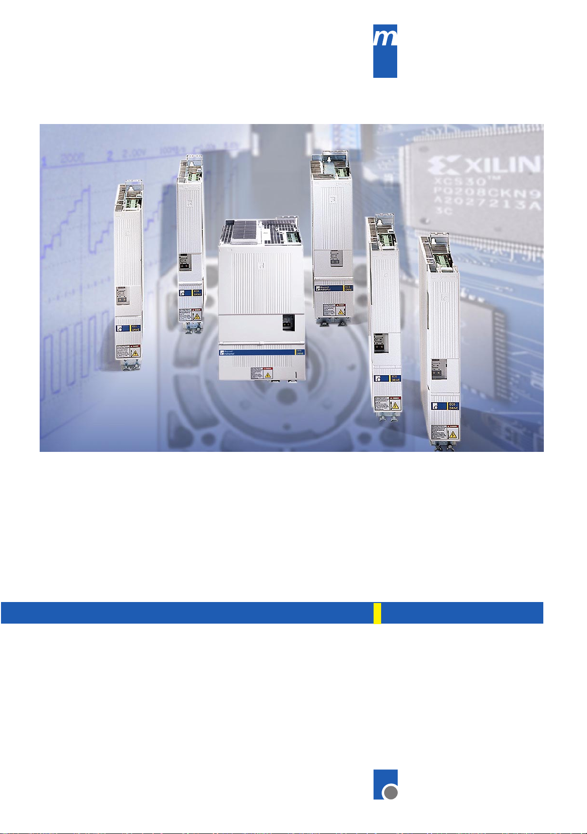
ECODRIVE03
Drive for Machine Tool Applications
With SERCOS-, Analog- and Parallelinterface
Troubleshooting Guide: SMT-02VRS
7=78)1
Rexroth
DOK-ECODR3-SMT-02VRS**-WA01-EN-P
Indramat
Page 2
About this Documentation ECODRIVE03 SMT-02VRS
Title
Type of Documentation
Document Typecode
Internal File Reference
Purpose of Documentation
Record of Revisions
ECODRIVE03 Drive for Machine Tool Applications With SERCOS-,
Analog- and Parallelinterface
Troubleshooting Guide: SMT-02VRS
DOK-ECODR3-SMT-02VRS**-WA01-EN-P
•
Box 71-02V-EN
•
Based on: SMT-02VRS
•
120-1000-B11-01/EN
The following documentation describes the functions of the firmware
FWA-ECODR3-SMT-02VRS.
This documentation serves:
•
for error diagnosis and error removal
Description Release
Notes
Date
DOK-ECODR3-SMT-02VRS**-WA01-DE-P 12.99 First edition
Copyright
Validity
Published by
Note
1999 Rexroth Indramat GmbH
Copying this document, giving it to others and the use or com munication
of the contents thereof without express authority, are forbidden. Offenders
are liable for the payment of damages. All rights are reserved in the event
of the grant of a patent or the registration of a utility model or des ign ( DIN
34-1).
All rights are reserved with respect to the content of this docum entation
and the availability of the product.
Rexroth Indramat GmbH
Bgm.-Dr.-Nebel-Str. 2 • D-97816 Lohr a. Main
Telephone 09352/40-0 • Tx 689421 • Fax 09352/40-4885
http://www.rexroth.com/indramat
Dept. ECD (MK/JR)
This document has been printed on chlorine-free bleached paper..
DOK-ECODR3-SMT-02VRS**-WA01-EN-P
Page 3
ECODRIVE03 SMT-02VRS About this Documentation
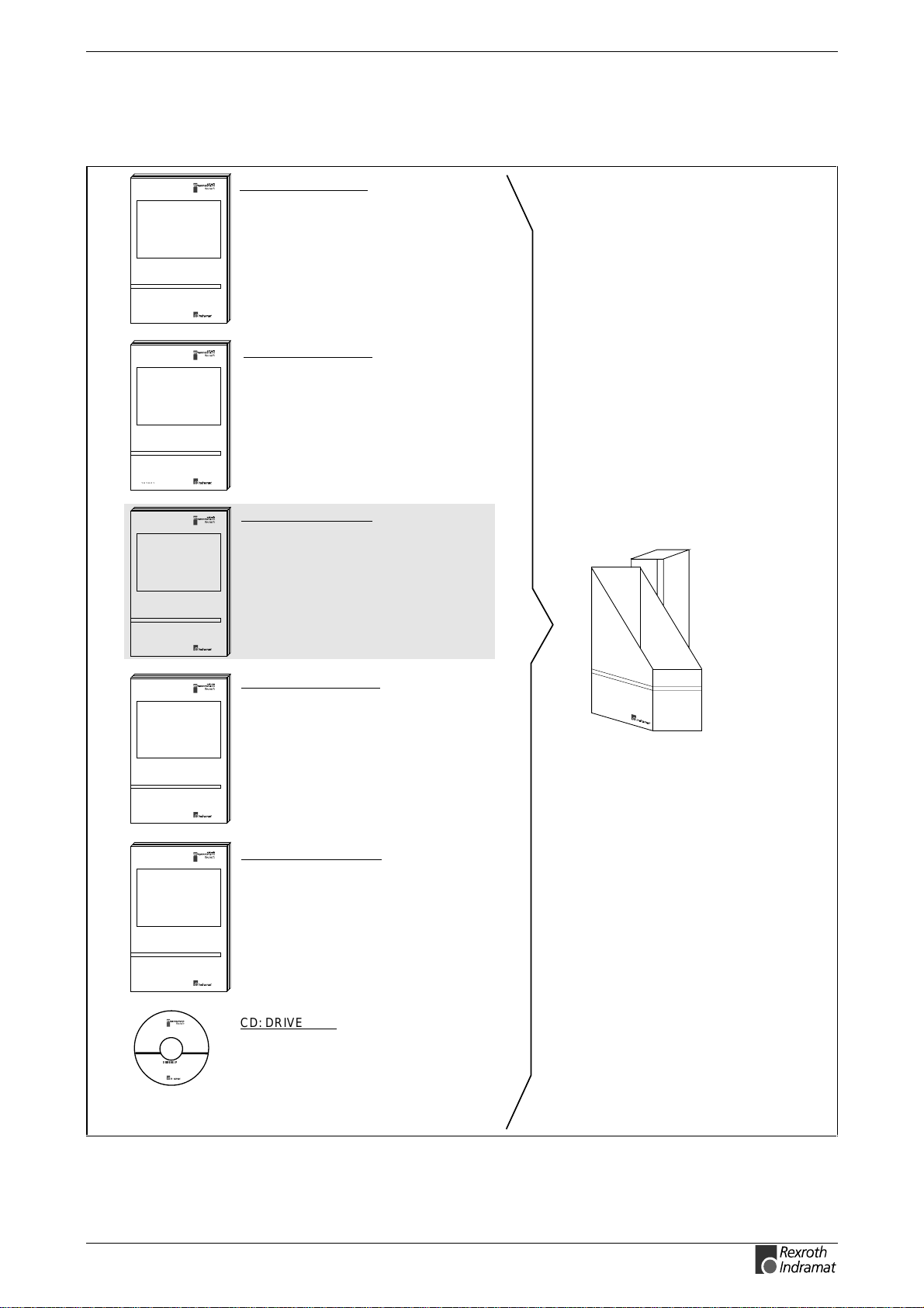
Summary of Documentation - Box
Functional Description:
Description of all implemented Function
based on SERCOS Parameters
FK
Order designation:
DOK-ECODR3-SMT-02VRS**-F K01-EN-P
Parameter Description:
A description of all parameters
used in the firmware
PA
Order designation:
DOK-ECODR3-SMT-02VRS**-PA01-EN-P
WA
FV
PR
Troubleshooting Guide:
-Explanation of the diagnostic states
-How to proceed when eliminating faults
Order designation:
DOK-ECODR3-SMT-02VRS**-WA01-EN-P
Firmware Version Notes:
Description of new and changed functions
in terms of the derivatives:
-FWA-ECODR3-SMT01VRS-MS
Order designation:
DOK-ECODR3-SMT-02VRS**-FV01-EN-P
Project Planning Manual:
-Planning control cabinet construction
-Planning the electric layout in the control cabinet
Order designation:
DOK-ECODR3-DKC**.3****-PR01-EN-P
Order designation
DOK-ECODR3-SMT-02VRS**-7101-EN-P
CD: DRIVEHELP
(6-:),)04
DOK-ECODR3-SMT-02VRS**-WA01-EN-P
Collection of Windows help systems which
contain documents on firmware derivatives
Order designation:
DOK-GENERL-D RIV EHELP**-GExx-M S-D0600
Page 4

About this Documentation ECODRIVE03 SMT-02VRS
Notes
DOK-ECODR3-SMT-02VRS**-WA01-EN-P
Page 5

ECODRIVE03 SMT-02VRS Contents I
Contents
1 Diagnostic Message Descriptions 1-1
Overview of the diagnostic message descriptions ..................................................................................1-1
Diagnostic Message T ypes......................................................................................................1-1
Construction of a diagnostic message.....................................................................................1-1
2 Safety Instructions for Electric Servo Drives and Controls 2-1
2.1 Introduction.....................................................................................................................................2-1
2.2 Explanations...................................................................................................................................2-1
2.3 Hazards by inappropriate use ........................................................................................................2-2
2.4 General Information .......................................................................................................................2-3
2.5 Protection against contact with electrical parts..............................................................................2-4
2.6 Protection by protective low voltage (PEL V) agains t electric al shock ........................................... 2-5
2.7 Protection against dangerous movements.....................................................................................2-6
2.8 Protection against magnetic and electromagnetic fields during operations and mounting............2-8
2.9 Protection against contact with hot parts....................................................................................... 2-8
2.10 Protection during handling and installation....................................................................................2-9
2.11 Battery safety.................................................................................................................................2-9
2.12 Protection against pressurized Systems......................................................................................2-10
3 Description of diagnostic letters F... and E... 3-1
3.1 Error diagnostic messages F......................................................................................................... 3-1
F207 Switching to uninitialized operation mode ......................................................................3-2
F208 UL The motor type has changed.................................................................................... 3-2
F209 PL Load parameter default values..................................................................................3-3
F218 Amplifier overtemp. shutdown ........................................................................................3-3
F219 Motor overtemp. shutdown.............................................................................................3-4
F220 Bleeder overload shutdown............................................................................................3-4
F221 Motor temp. surveillance defective.................................................................................3-5
F223 Error during initialisation of the parking axis...................................................................3-5
F224 Maximum braking time exceeded...................................................................................3-6
F226 Undervoltage in power section .......................................................................................3-6
F228 Excessive deviation ........................................................................................................3-7
F229 Encoder 1 failure: quadrant error....................................................................................3-7
F230 Max. signal frequency of encoder 1 exceeded...............................................................3-7
F236 Excessive position feedbac k difference..........................................................................3-8
F237 Excessive position command difference ........................................................................3-9
F242 Encoder 2 failure: signal amplitude wrong...................................................................... 3-9
F245 Encoder 2 failure: quadrant error..................................................................................3-10
DOK-ECODR3-SMT-02VRS**-WA01-EN-P
Page 6

II Contents ECODRIVE03 SMT-02VRS
F246 Max signal frequency of encoder 2 exceeded..............................................................3-11
F248 Low battery voltage.......................................................................................................3-11
F253 Incr. encoder emulator: pulse frequency too high........................................................3-12
F260 Command current limit shutoff...................................................................................... 3-12
F262 External short at status outputs....................................................................................3-12
F267 Erroneous internal hardware s ynchron i zation ..............................................................3- 13
F269 Error during release of the motor holding brake...........................................................3-13
F276 Absolute encoder out of allowed window .....................................................................3-14
F277 Current measurement trim wrong.................................................................................3-14
F281 Mains fault .................................................................................................................... 3-15
F386 No ready signal from supply module ............................................................................ 3-15
F401 Double MST failure shutdown ......................................................................................3-15
F402 Double MDT failure shutdown ...................................................................................... 3-16
F403 Invalid communication phase shutdown.......................................................................3-16
F404 Error during phase progression....................................................................................3-16
F405 Error during phase regression......................................................................................3-17
F406 Phase switching without ready signal...........................................................................3-17
F434 Emergency-Stop...........................................................................................................3-17
F629 Positive travel limit exceeded .......................................................................................3-17
F630 Negative travel limit exceeded...................................................................................... 3-18
F634 Emergency-Stop...........................................................................................................3-19
F643 Positive travel limit switch detected..............................................................................3-19
F644 Negative travel limit switch detected ............................................................................3-19
F811 Commutation offset could not be determined...............................................................3-20
F812 Motion range exceeded during commutation ...............................................................3-20
F822 Encoder 1 failure: signal amplitude wrong.................................................................... 3-21
F860 Overcurrent: short in power stage................................................................................3-22
F870 +24Volt DC error...........................................................................................................3-22
F873 Power supply driver stages fault...................................................................................3-23
F878 Velocity loop error.........................................................................................................3-23
F879 Velocity limit S-0-0091 exc eede d .................................................................................3-24
3.2 Warning diagnostic messages.....................................................................................................3-25
E221 Warning Motor temp. surveillance defective ................................................................3-25
E225 Motor overload..............................................................................................................3-26
E226 Undervoltage in power section..................................................................................... 3-26
E247 Interpolation velocity = 0...............................................................................................3-26
E248 Interpolation acceleration = 0.......................................................................................3-27
E249 Positioning velocity >= S-0-0091..................................................................................3-27
E250 Drive overtemp. prewarning .........................................................................................3-28
E251 Motor overtemp. prewarning ........................................................................................3-28
E252 Bleeder overload prewarning .......................................................................................3-29
E253 Target position out of travel range................................................................................3-29
E254 Not homed....................................................................................................................3-30
E255 Feedrate-override S-0-0108 = 0................................................................................... 3-30
E256 Torque limit = 0.............................................................................................................3-31
E257 Continuous current limit active .....................................................................................3-31
DOK-ECODR3-SMT-02VRS**-WA01-EN-P
Page 7

ECODRIVE03 SMT-02VRS Contents III
E258 Selected process block is not programmed. ................................................................3-31
E259 Command velocity limit active......................................................................................3-32
E260 Command Current limit active......................................................................................3-32
E261 Continuous current limit prewarning.............................................................................3-32
E263 Velocity command value > limit S-0-0091.................................................................... 3-33
E264 Target position out of num. range ................................................................................3-33
E269 Brake torque too low.....................................................................................................3-33
E281 Mains fault ....................................................................................................................3-34
E386 No ready signal from supply module............................................................................3-34
E408 Invalid addressing of MDT-data container A................................................................ 3-34
E409 Invalid addressing of AT-data container A ...................................................................3-34
E410 Slave not scanned or address 0...................................................................................3-35
E825 Overvoltage in power stage..........................................................................................3-35
E826 Undervoltage in power section..................................................................................... 3-35
E829 Positive position limit exceeded ................................................................................... 3-36
E830 Negative position limit exceeded..................................................................................3-36
E831 Position limit reached during jog ..................................................................................3-37
E834 Emergency-Stop........................................................................................................... 3-37
E843 Positive limit switch activated.......................................................................................3-37
E844 Negative limit switch activated .....................................................................................3-38
E881 Mains fault ....................................................................................................................3-38
E886 No ready signal from supply module............................................................................3-38
4 Description of Diagnostic Letters B..., C..., D... and A... 4-1
4.1 Command Diagnostic Messages B..., C... and D...........................................................................4-1
B000 Pulse wire/Resolver offs et detectio n ..............................................................................4-2
B001 Motor does not have resolver feedback.........................................................................4-2
B002 Drive active at command start........................................................................................4-2
B003 Power supply is off .........................................................................................................4-2
B004 S pulse not found within travel range ............................................................................. 4-2
B005 Error writing to feedback EEPROM................................................................................4-2
B006 Error in feedback processor, SDAI does not show 1 .....................................................4-2
B008 Drive must be in operation mode (phase 4) ...................................................................4-2
B009 Drive does not control in secondary operation mode 1..................................................4-2
B010 5 pulses found, but min. distance to move not reached.................................................4-3
B011 SDAI goes immeadiately back to 0, old PIC version......................................................4-3
B012 Master password required..............................................................................................4-3
B013 Shaft does not turn as expected.....................................................................................4-3
B100 Command Release motor holding brake........................................................................4-3
B101 Command not enabled...................................................................................................4-3
B200 Brake check command...................................................................................................4-3
B201 Brake check only with drive enable................................................................................4-3
B202 Error during bedding in the brake...................................................................................4-4
B203 Brake torque too low.......................................................................................................4-4
C100 Communication phase 3 transition check ......................................................................4-4
C101 Invalid communication parameter (S-0-0021)................................................................4-5
DOK-ECODR3-SMT-02VRS**-WA01-EN-P
Page 8

IV Contents ECODRIVE03 SMT-02VRS
C102 Limit error communication parameter (S-0-0021).......................................................... 4-5
C104 Config. IDN for MDT not configurable............................................................................4-5
C105 Configurated length > max. length for MDT...................................................................4-6
C106 Config. IDN for AT not configurable ...............................................................................4-6
C107 Configurated length > max. length for AT ......................................................................4-6
C108 Time slot parameter > Sercos cycle time.......................................................................4-7
C109 Position of data record in MDT (S-0-0009) even ...........................................................4-7
C110 Length of MDT (S-0-0010) odd ......................................................................................4-7
C111 ID9 + Record length - 1 > length MDT (S-0-0010).........................................................4-8
C112 TNcyc (S-0-0001) or TScyc (S-0-0002) error.................................................................4-8
C113 Relation TNcyc (S-0-0001) to TScyc (S-0-0002) error...................................................4-8
C114 T4 > TScyc (S-0-0002) - T4min (S-0-0005) ...................................................................4-9
C115 T2 too small.................................................................................................................... 4-9
C118 Order of MDT configuration wrong.................................................................................4-9
C200 Communication phase 4 transition check ....................................................................4-10
C201 Invalid parameter(s) (->S-0- 002 2)................................................................................4-10
C202 Parameter limit error (->S-0-0022)...............................................................................4-10
C203 Parameter calculation error (->S-0-0022) ....................................................................4-10
C204 Motor type P-0-4014 incorrect......................................................................................4-11
C210 Feedback 2 required (->S-0-0022)...............................................................................4-11
C211 Invalid feedback data (->S-0-0022)..............................................................................4-11
C212 Invalid amplifier data (->S-0- 00 22)...............................................................................4-12
C213 Position data scaling error............................................................................................ 4-12
C214 Velocity data scaling error............................................................................................4-13
C215 Acceleration data scaling error.....................................................................................4-13
C216 Torque/force data scaling error....................................................................................4-14
C217 Feedback1 data reading error......................................................................................4-14
C218 Feedback 2 data reading error.....................................................................................4-14
C220 Feedback 1 initializing error .........................................................................................4-15
C221 Feedback 2 initializing error .........................................................................................4-15
C223 Input value for max. range too high..............................................................................4-16
C227 Modulo range error.......................................................................................................4-16
C234 Encoder combination not possib le ...............................................................................4-16
C235 Load-side motor encoder with inductance motor only .................................................4-17
C236 Feedback 1 required (P-0-0074)..................................................................................4-17
C238 Wrong function of encoder 2........................................................................................4-17
C300 Command Set absolute measurin g..............................................................................4-17
C302 Absolute measuring system not installed.....................................................................4-18
C400 Switching to parameter mode ......................................................................................4-18
C401 Drive active, switching not allowed ..............................................................................4-18
C402 Only allowed without master........................................................................................ 4-18
C500 Reset class 1 diagnostic, error reset............................................................................4-19
C600 Drive controlled homing procedure command .............................................................4-19
C601 Homing only possible with drive enable.......................................................................4-19
C602 Distance home switch - reference mark erroneous .....................................................4-19
C604 Homing of absolute encoder not possible....................................................................4-19
DOK-ECODR3-SMT-02VRS**-WA01-EN-P
Page 9

ECODRIVE03 SMT-02VRS Contents V
C606 Reference mark not detected.......................................................................................4-20
C700 Basic load.....................................................................................................................4-20
C702 Default parameters not available .................................................................................4-21
C703 Default parameters invalid ...........................................................................................4-21
C704 Parameters not copyable ............................................................................................. 4-21
C800 Default parameter load................................................................................................. 4-21
C801 Parameter default value er rone ous (-> S-0- 00 21) .......................................................4-22
C802 Locked with password..................................................................................................4-22
C900 Position spindle command ...........................................................................................4-22
C902 Spindle positioning requires drive enable ....................................................................4-22
C905 Positioning with non-init. abs ol ute enc o der im pos s ible ................................................ 4-22
C906 Error during search for zero pulse................................................................................ 4-23
D300 Command adjust commutation ....................................................................................4-23
D301 Drive not ready for commutation command................................................................. 4-23
D302 Torque/Force too small to move ..................................................................................4-24
D303 Drive in control at start of command ............................................................................4-24
D306 Power is off...................................................................................................................4-24
D307 Drive does not move .................................................................................................... 4-24
D308 No adjustment with asynchronous motor.....................................................................4-24
D309 Proceed to phase 4 ......................................................................................................4-25
D310 Input master password.................................................................................................4-25
D311 Commutation offset could not be determined..............................................................4-25
D312 Motion range exceeded during commutation...............................................................4-25
D400 Positive stop drive procedure command......................................................................4-26
D401 ZKL1-Error at command start.......................................................................................4-26
D500 Command Get mark position .......................................................................................4-26
D501 Incremental encoder required ......................................................................................4-26
D600 Cancel reference point procedure command...............................................................4-27
D700 Parking axis command.................................................................................................4-27
D701 Parking axis only while drive is disabled......................................................................4-27
D900 Command automatic loop tuning .................................................................................4-28
D901 Start requires drive enable...........................................................................................4-28
D902 Motor feedback data not valid......................................................................................4-28
D903 Inertia detection failed .................................................................................................. 4-29
D904 Gain adjustment failed..................................................................................................4-29
D905 Travel range invalid, P-0-0166 & P-0-0167.................................................................. 4-30
D906 Travel range exceeded.................................................................................................4-30
4.2 Status diagnostic messages ........................................................................................................ 4-31
A000 Communication phase 0...............................................................................................4-31
A001 Communication phase 1...............................................................................................4-31
A002 Communication phase 2...............................................................................................4-31
A003 Communication phase 3...............................................................................................4-32
A010 Drive HALT...................................................................................................................4-32
A012 Control and power sections ready for operation ..........................................................4-33
A013 Ready for power on ......................................................................................................4-33
A100 Drive in TORQUE control.............................................................................................4-33
DOK-ECODR3-SMT-02VRS**-WA01-EN-P
Page 10

VI Contents ECODRIVE03 SMT-02VRS
A101 Drive in VELOCITY control ........................................................................................... 4-33
A102 Position mode with encoder 1 ......................................................................................4-33
A103 Position mode with encoder 2 ......................................................................................4-33
A104 Position mode lagless, encoder 1 ................................................................................4-34
A105 Position control lagless, feedback 2.............................................................................4-34
A106 Drive controlled interpolation, encoder 1......................................................................4-34
A107 Drive controlled interpolation, encoder 2......................................................................4-34
A108 Drive controlled interpolation, lagless, encoder 1 ........................................................4-35
A109 Drive controlled interpolation, lagless, encoder 2 ........................................................4-35
A146 Relative drive controlled interpolation, encoder 1........................................................4-35
A147 Relative drive controlled interpolation, encoder 2........................................................4-36
A148 Relative drive contr. interpolation, enc. 1, lagless........................................................4-36
A149 Relative drive contr. interpolation, enc. 2, lagless........................................................4-37
A203 Stepper position mode..................................................................................................4-37
A204 Stepper position mode, lagless ....................................................................................4-37
A206 Process block mode, encoder 1...................................................................................4-37
A207 Process block mode lagless, encoder 1.......................................................................4-38
A208 JOG mode positive.......................................................................................................4-38
A210 Process block mode, encoder 2...................................................................................4-38
A211 Process block mode lagless, encoder 2.......................................................................4-38
A218 JOG mode negative......................................................................................................4-38
A400 Automatic drive check and adjustment.........................................................................4-39
A401 Drive deceleration to standstill .....................................................................................4-39
A800 Unknown operation mode ............................................................................................4-39
4.3 Diagnostic messages for basic initialization and after fatal System errors..................................4-40
Diagnostic Message Display: -0.............................................................................................4-40
Diagnostic Message Display: -1.............................................................................................4-40
Diagnostic Message Display: -2.............................................................................................4-40
Diagnostic Message Display: -3.............................................................................................4-40
Diagnostic Message Display: -4.............................................................................................4-40
Diagnostic Message Display: -5.............................................................................................4-40
Diagnostic Message Display: -6.............................................................................................4-40
Diagnostic Message Display:
Diagnostic Message Display: E1 ...........................................................................................4-41
Diagnostic Message Display: E2 ...........................................................................................4-41
Diagnostic Message Display: E3 ...........................................................................................4-41
Diagnostic Message Display: E4 ...........................................................................................4-41
Diagnostic Message Display: E5 ...........................................................................................4-41
4.4 Operation Status ..........................................................................................................................4-42
bb...........................................................................................................................................4-42
Ab...........................................................................................................................................4-42
AC..........................................................................................................................................4-42
AE ..........................................................................................................................................4-42
AF...........................................................................................................................................4-42
AH..........................................................................................................................................4-42
Jb ...........................................................................................................................................4-42
(2 dots) .............................................................................4-40
DOK-ECODR3-SMT-02VRS**-WA01-EN-P
Page 11

ECODRIVE03 SMT-02VRS Contents VII
JF...........................................................................................................................................4-42
P0...........................................................................................................................................4-43
P1...........................................................................................................................................4-43
P2...........................................................................................................................................4-43
P3...........................................................................................................................................4-43
PL...........................................................................................................................................4-43
UL...........................................................................................................................................4-43
5 Replacing or Exchanging Drive Components 5-1
5.1 Procedure on Replacing the Unit...................................................................................................5-3
Replacing the DKC: .................................................................................................................5-3
Replacing the Motor:................................................................................................................ 5-4
Replacing cables:.....................................................................................................................5-4
6 Replacing Firmware 6-7
6.1 Replacing the Parameter Module ..................................................................................................6-7
6.2 Replacing the Firmware Module.................................................................................................... 6-8
6.3 Replacing the Programming Module (complete module)...............................................................6-8
7 Index 7-1
8 Kundenbetreuungsstellen - Sales & Service Facilities 8-1
DOK-ECODR3-SMT-02VRS**-WA01-EN-P
Page 12

VIII Contents ECODRIVE03 SMT-02VRS
Notes
DOK-ECODR3-SMT-02VRS**-WA01-EN-P
Page 13
ECODRIVE03 SMT-02VRS Diagnostic Message Descriptions 1-1
1 Diagnostic Message Descriptions
Overview of the diagnostic message descriptions
Diagnostic Message Types
Each operational state of the drive will be characterized with a diagnostic
message.
Differentiations will be made between:
•
Error diagnostic messages
•
Warning diagnostic messages
•
Command diagnostic messages
•
Drive Mode diagnostic messages
•
Operation status
Construction of a diagnostic message
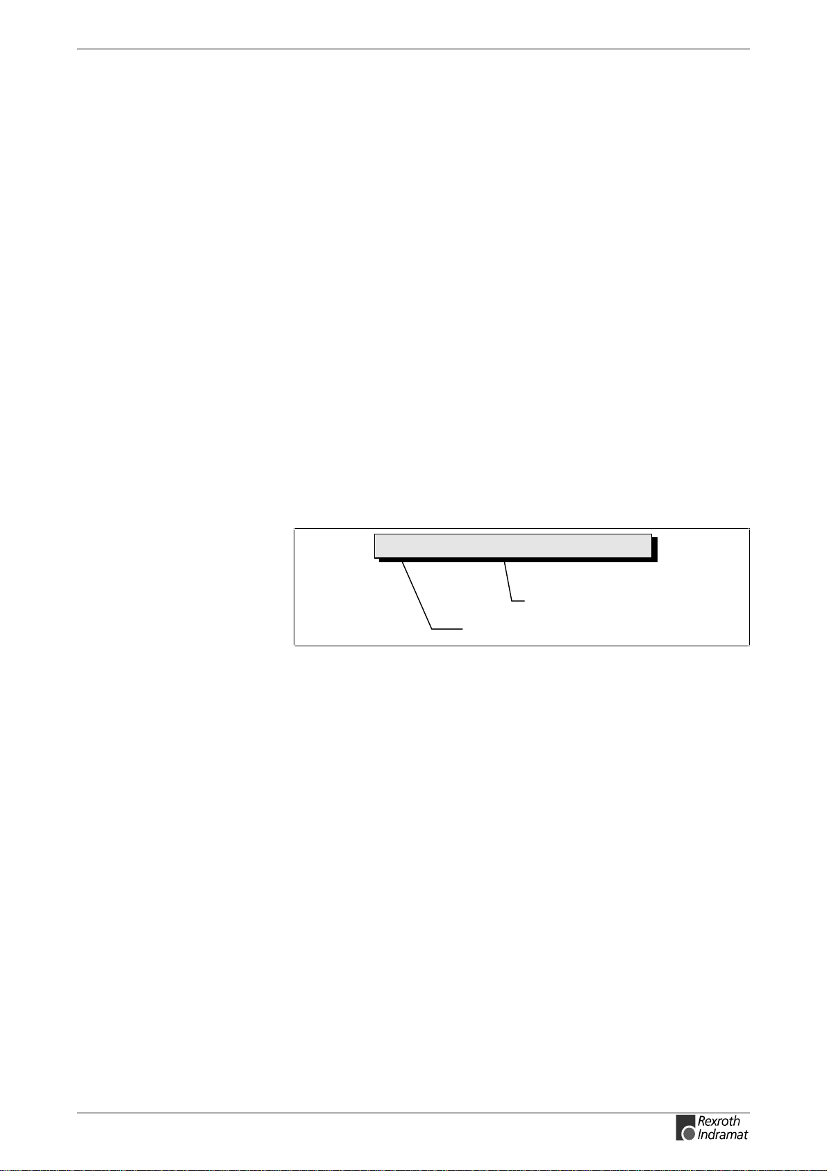
A diagnostic message consists of:
•
A diagnostic number and a
•
diagnostic text
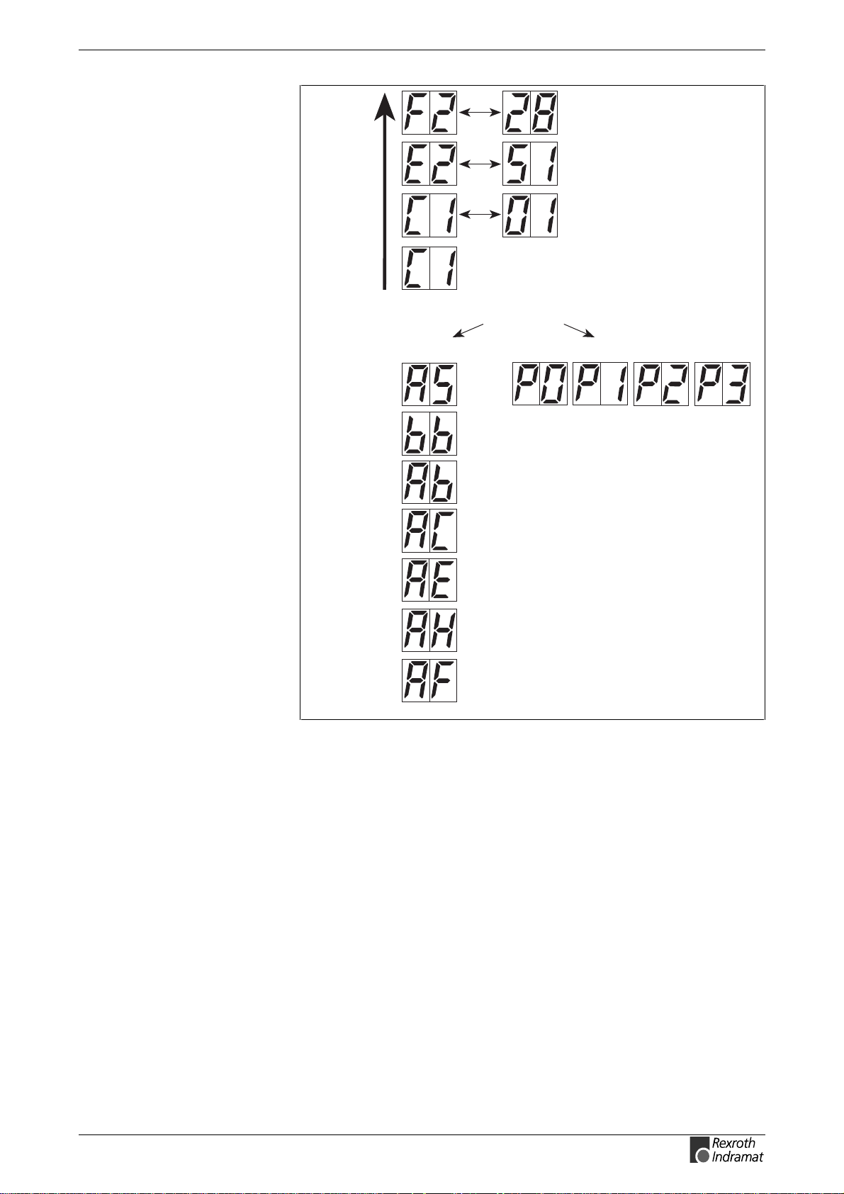
F228 Excessive Control Deviation
Fig. 1-1: Diagnostic message with a diagnostic number and text.
For the example in the graphic, "F2" and "28" are shown alternately on the
H1-Display.
The control system can read out the diagnostic number in hexadecimal
form with the S-0-0390, Diagnostic message number parameter.
In addition, the drive allocates to the control system the diagnostic
number and diagnostic text as a string F228 Excessive deviation with
the S-0-0095, Diagnostic message parameter.
Diagnostic message
Diagnostic message number
DOK-ECODR3-SMT-02VRS**-WA01-EN-P
Page 14
1-2 Diagnostic Message Descriptions ECODRIVE03 SMT-02VRS
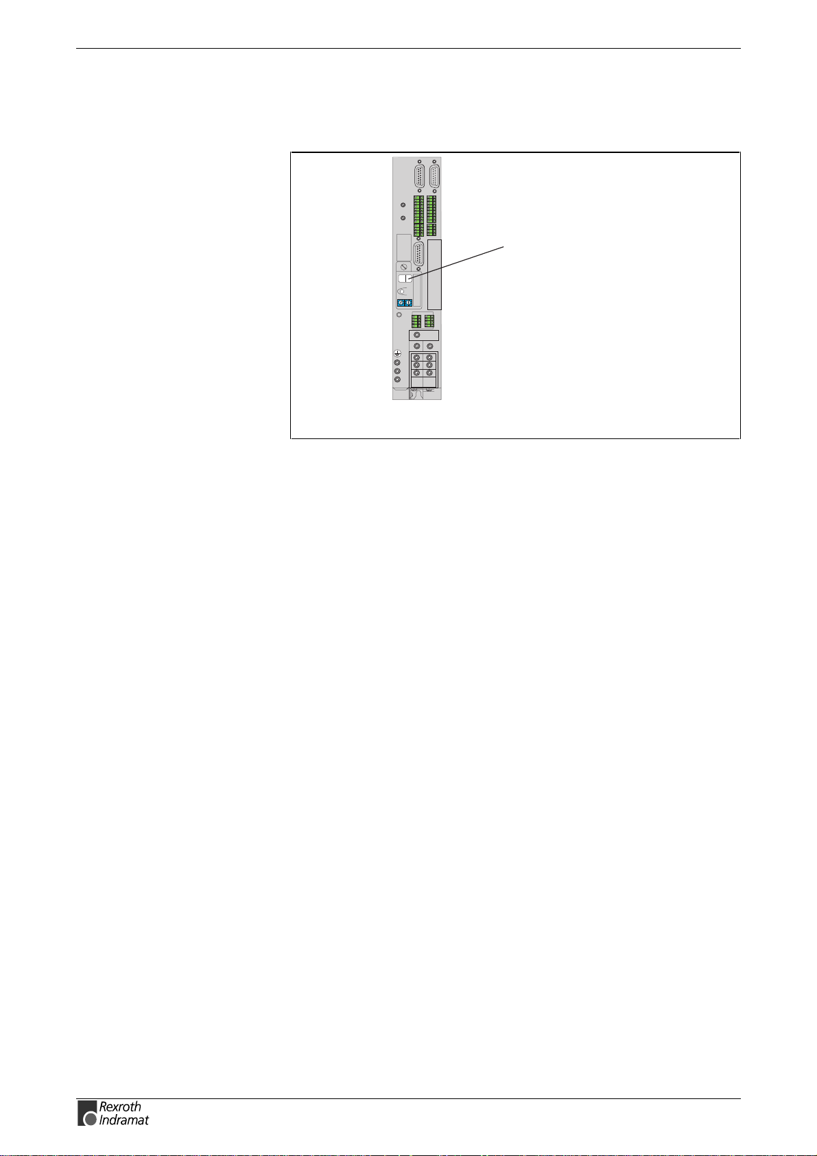
H1-Display
The H1-Display serves as an optical display of the diagnostic message on
the drive.
123456789
123456789
11121314151617 18
5678
1234
1234
Barcode
Typenschild
H1
S1
S3 S2
0
0
1
1
9
9
2
2
Barcode
8
8
3
3
7
7
4
4
6
6
5
5
1234
1234
5678
DKC
H1-Display
FA5047f1.fh7
Fig. 1-2: H1-/Display
The diagnostic number appears on this two-positional seven-segment
display. The image can be seen on the "Diagnostic Message Priority
Display".
This display quickly shows the current operation status without the use of
a communications interface.
The operating mode cannot be seen from the H1-Display. If the drive
follows the operating mode and no command was activated, then the
symbol "AF" appears on the display.
Diagnostic Message Output
Priority
If more than one diagnostic m essage is waiting, then the message with
the highest priority will be displayed.
The following graphic classifies operation status in order of importance.
DOK-ECODR3-SMT-02VRS**-WA01-EN-P
Page 15
ECODRIVE03 SMT-02VRS Diagnostic Message Descriptions 1-3
P
R
I
O
R
I
T
Y
Operation lock
active
Ready to
operate
Drive ready
Drive automatic
check
Error
Warning
Command error
Command active
Ready to operate ?
yes no
Communicationphase
Drive error
reaction
Drive Halt
Drive is
following
operating mode
Fig. 1-3: Diagnostic message priority diagram
Da0001f1.fh7
Clear Coded Diagnostic Message
The clear coded diagnostic message contains the diagnostic number
followed by the diagnostic text, as shown in the example, "Excessive
Output Error" (Fig. 1-1). It can be read out with the S-0-0095, Diagnostic
message parameter and directly displays the operation status on an
operator surface.
The clear coded diagnostic message will be switched to the current
language.
DOK-ECODR3-SMT-02VRS**-WA01-EN-P
Page 16

1-4 Diagnostic Message Descriptions ECODRIVE03 SMT-02VRS
Notes
DOK-ECODR3-SMT-02VRS**-WA01-EN-P
Page 17
ECODRIVE03 SMT-02VRS Safety Instructions for Electric Servo Drives and Controls 2-1
2 Safety Instructions for Electric Servo Drives and
Controls
2.1 Introduction
Read these instructions before the equipment is used and eliminate the
risk of personal injury or property damage. Follow these safety
instructions at all times.
Do not attempt to install, use or service this equipment without first
reading all documentation provided with the product. Read and
understand these safety instructions and all user documentation of the
equipment prior to working with the equipment at any time. If you do not
have the user documentation for your equipment contact your local
Rexroth Indramat representative to send this documentation immediately
to the person or persons responsible for the safe operation of this
equipment.
If the product is resold, rented or tr ansferred or passed on to others, then
these safety instructions must be delivered with the product.
2.2 Explanations
Inappropriate use of this equipment, fail ure t o
follow the safety instructions in this document
or tampering with the product, i ncl uding
WARNING
disabling of safety devices, may result in
product damage, personal injury, severe
electrical shock or death !
The safety warnings in this documentation describe individual degrees of
hazard seriousness in compliance with ANSI:
Warning symbol with signal
word
DANGER
Degree of hazard seriousness
The degree of hazard seriousness
describes the consequences resulting from
non-compliance with the safety guidelines.
Bodily harm or product damage will occur.
DOK-ECODR3-SMT-02VRS**-WA01-EN-P
Death or severe bodily harm may occur.
WARNING
Death or severe bodily harm may occur.
CAUTION
Fig. 2-4: Classes of danger with ANSI
Page 18
2-2 Safety Instructions for Electric Servo Drives and Controls ECODRIVE03 SMT-02VRS
2.3 Hazards by inappropriate use
High voltage and high discharge current !
Danger to life, risk of severe electrical shock
and risk of injury !
DANGER
Dangerous movements ! Danger to life and risk
of injury or equipment damage by unintentional
motor movements !
DANGER
High electrical voltage due to wrong
connections ! Danger to life, severe electrical
shock and severe bodily injury !
WARNING
WARNING
CAUTION
CAUTION
Health hazard for persons with heart
pacemakers, metal implants and hearing aids i n
proximity to electrical equipment !
Surface of machine housing could be extremely
hot ! Danger of injury ! Danger of burns !
Risk of injury due to inappropriate handling !
Bodily injury caused by crushing, shearing,
cutting and mechanical shock !
Risk of injury due to inappropriate handling of
batteries !
CAUTION
DOK-ECODR3-SMT-02VRS**-WA01-EN-P
Page 19

ECODRIVE03 SMT-02VRS Safety Instructions for Electric Servo Drives and Controls 2-3
2.4 General Information
•
Rexroth Indramat GmbH is not liable for damages resulting from
failure to observe the warnings given in these documentation.
•
Order operating, maintenance and safety instructions in your language
before starting up the machine. If you find that due to a translation
error you can not completely understand the documentation for your
product, please ask your supplier to clarify.
•
Proper and correct transport, storage, assembly and installation as
well as care in operation and maintenance are prerequisites for
optimal and safe operation of this equipment.
•
Trained and qualified personnel in electrical equipment :
Only trained and qualified personnel may work on this equipment or
within its proximity. Personnel are qualified if they have sufficient
knowledge of the assembly, installation and operation of the product
as well as an understanding of all warnings and precautionary
measures noted in these instructions.
Furthermore, they should be trained, instructed and qualif ied to switch
electrical circuits and equipment on and off, to ground them and to
mark them according to the requirements of saf e work practices and
common sense. T hey must have adequate safety equipment and be
trained in first aid.
•
Only use spare parts and accessories approved by the manufacturer.
•
Follow all safety regulations and requirements for the specific
application as practiced in the country of use.
•
The equipment is designed for installation on commercial machinery.
European countries: see directive 89/392/EEC (machine guideline).
•
The ambient conditions given in the product documentation must be
observed.
•
Use only safety features that are clearly and explicitly approved in the
Project Planning manual.
For example, the following areas of use are not allowed: Construction
cranes, Elevators used for people or freight, Devices and vehicles to
transport people, Medical applications, Refinery plants, the transport
of hazardous goods, Radioactive or nuclear applications, Applications
sensitive to high frequency, mining, food processing, Control of
protection equipment (also in a machine).
•
Start-up is only permitted once it is sure that the m ac hine, in which the
product is installed, complies with the requirements of national saf ety
regulations and safety specifications of the application.
•
Operation is only permitted if the national EMC regulations for the
application are met.
The instructions for installation in accordanc e with EMC requirements
can be found in the INDRAMAT docum ent "EMC in Drive and Control
Systems”.
The machine builder is responsible for compliance with the limiting
values as prescribed in the national regulations and specific EMC
regulations for the application.
European countries: see Directive 89/336/EEC (EMC Guideline).
U.S.A.: See National Electrical Codes (NEC), National Electrical
Manufacturers Association (NEMA), and local building codes. T he user of
this equipment must consult the above noted items at all times.
DOK-ECODR3-SMT-02VRS**-WA01-EN-P
• Technical data, connections and operational conditions are specified in
the product documentation and must be followed at all times.
Page 20
2-4 Safety Instructions for Electric Servo Drives and Controls ECODRIVE03 SMT-02VRS
2.5 Protection against contact with electrical parts
Note : This section refers to equipment with voltages above 50 Volts.
Making contact with parts conducting voltages above 50 volts could be
dangerous to personnel and cause an electrical shoc k. When operating
electrical equipment, it is unavoidable that som e parts of the unit conduc t
dangerous voltages.
High electrical voltage ! Danger to life, severe
electrical shock and severe bodily injury !
⇒
Only those trained and qualified to work with or on
DANGER
electrical equipment are permitted to operate,
maintain or repair this equipment.
⇒
Follow general construction and safety regulations
when working on electrical installations.
⇒
Before switching on power the ground wire must be
permanently connected to all electrical units according to the connection diagram.
⇒
Do not operate electrical equipment at any time if the
ground wire is not permanently connected, even for
brief measurements or tests.
⇒
Before working with electrical parts with voltage
potentials higher than 50 V, the equipment m ust be
disconnected from the mains voltage or power
supply.
⇒
The following should be observed with electrical
drives, power supplies, and filter components:
Wait five (5) minutes after switching off power to
allow capacitors to discharge before beginning work .
Measure the voltage on the capacitors before
beginning work to make sure that the equipment is
safe to touch.
⇒
Never touch the electrical connection points of a
component while power is turned on.
⇒
Install the covers and guards provided with the
equipment properly before switching the equipment
on. Prevent contact with live parts at any time.
⇒
A residual-current-operated protective device (r.c.d.)
must not be used on an electric drive ! Indirect
contact must be prevented by other means, for
example, by an overcurrent protective device.
⇒ Equipment that is built into machines must be
secured against direct contact. Use appropriate
housings, for example a control cabinet.
European countries: according to EN 50178/1998,
section 5.3.2.3.
U.S.A: See National Electrical Codes (NEC), National
Electrical Manufacturers Association (NEMA) and local
building codes. The user of this equipment m ust observe
the above noted instructions at all times.
DOK-ECODR3-SMT-02VRS**-WA01-EN-P
Page 21
ECODRIVE03 SMT-02VRS Safety Instructions for Electric Servo Drives and Controls 2-5
To be observed with electrical drives, power supplies, and filter
components:
High electrical voltage ! High leakage current !
Danger to life, danger of injury and bodily harm
from electrical shock !
⇒
DANGER
Before switching on power for electrical units, all
housings and motors must be permanently grounded
according to the connection diagram. This applies
even for brief tests.
⇒
Leakage current exceeds 3.5 mA. Therefore the
electrical equipment and units must always be firm ly
connected to the supply network.
⇒
Use a copper conductor with at least 10 mm² cross
section over its entire course for this protective
connection !
⇒
Prior to startups, even for brief tests, always connect
the protective conductor or connect with ground wire.
High voltage levels can occur on the housing that
could lead to severe electrical shock and personal
injury.
European countries: EN 50178/1998, section 5.3.2.1.
USA: See National Electrical Codes (NEC), National
Electrical Manufacturers Association (NEMA), and local
building codes. The user of this equipment m u st m aintain
the above noted instructions at all times.
2.6 Protection by protective low voltage (PELV) against electrical shock
All connections and terminals with voltages between 5 and 50 Volts on
INDRAMAT products are protective low voltages designed in accordance
with the following standards on contact safety :
•
International: IEC 364-4-411.1.5
•
EU countries: see EN 50178/1998, section 5.2.8.1.
High electrical voltage due to wrong
connections ! Danger to life, severe electrical
shock and severe bodily injury !
⇒
WARNING
Only equipment, electrical com ponents and cables of
the protective low voltage type (PELV = Protective
Extra Low Voltage) may be connected to all
terminals and clamps with 0 to 50 Volts.
⇒ Only safely isolated voltages and electrical circuits
may be connected. Safe isolation is achieved, for
example, with an isolating transformer, an optoelectronic coupler or when battery-operated.
DOK-ECODR3-SMT-02VRS**-WA01-EN-P
Page 22

2-6 Safety Instructions for Electric Servo Drives and Controls ECODRIVE03 SMT-02VRS
2.7 Protection against dangerous movements
Dangerous movements can be caused by faulty control or the connected
motors. These causes are be various such as:
•
unclean or wrong wiring of cable connections
•
inappropriate or wrong operation of equipment
•
malfunction of sensors, encoders and monitoring circuits
•
defective components
•
software errors
Dangerous movements can occur immediately after equipment is
switched on or even after an unspecified time of trouble-free operation.
The monitors in the drive components make faulty operation almost
impossible. Regarding personnel safety, especially the danger of bodily
harm and property damage, this alone should not be relied upon to
ensure complete safety. Until the built-in monitors become active and
effective, it must be assumed in any case that some faulty drive
movements will occur. The extent of these faulty drive movements
depends upon the type of control and the state of operation.
DOK-ECODR3-SMT-02VRS**-WA01-EN-P
Page 23

ECODRIVE03 SMT-02VRS Safety Instructions for Electric Servo Drives and Controls 2-7
Dangerous movements ! Danger to life and risk
of injury or equipment damage !
⇒
Personnel protection must be s ecured for the above
DANGER
listed reason by means of superordinate m onitors or
measures.
These are instituted in accordanc e with the specific
situation of the facility and a danger and fault
analysis conducted by the manufacturer of the
facility. All the safety regulations that apply to this
facility are included therein. By switching off,
circumventing or if safety devices have simply not
been activated, then random m ac hine movements or
other types of faults can occur.
Avoiding accidents, injury or property damage :
⇒
Keep free and clear of the machine’s range of
motion and moving parts. Prevent people from
accidentally entering the machine’s range of
movement:
- use protective fences
- use protective railings
- install protective coverings
- install light curtains or light barriers
⇒
Fences must be strong enough to withstand
maximum possible momentum.
⇒
Mount the emergency stop switch (E-stop) in the
immediate reach of the operator. Verify that the
emergency stop works before startup. Don’t operate
the machine if the emergency stop is not working.
⇒
Isolate the drive power connection by means of an
emergency stop circuit or use a start-inhibit system
to prevent unintentional start-up.
⇒
Make sure that the drives are brought to standstill
before accessing or entering the danger zone.
⇒
Disconnect elec tric al power to the equipment using a
master switch and secure the switch against
reconnection for :
- maintenance and repair work
- cleaning of equipment
- long periods of discontinued equipment use
⇒
Avoid operating high-frequency, remote control and
radio equipment near electronics c ircuits and supply
leads. If use of such equipment cannot be avoided,
verify the system and the plant for possible
malfunctions at all pos sible positions of normal use
before the first start-up. If necessary, perform a
special electromagnetic compatibility (EMC) test on
the plant.
DOK-ECODR3-SMT-02VRS**-WA01-EN-P
Page 24
2-8 Safety Instructions for Electric Servo Drives and Controls ECODRIVE03 SMT-02VRS
2.8 Protection against magnetic and electromagnetic fields during operations and mounting
Magnetic and electromagnetic fields generated by current-carrying
conductors and permanent m agnets in m otors represent a ser ious health
hazard to persons with heart pacemakers, metal implants and hearing
aids.
Health hazard for persons with heart
pacemakers, metal implants and hearing aids i n
proximity to electrical equipment !
⇒
WARNING
Persons with pacemakers, metal implants and
hearing aids are not permitted to enter following
areas:
- Areas in which electrical equipm ent and parts are
mounted, being operated or started up.
- Areas in which parts of motors with permanent
magnets are being stored, operated, repaired or
mounted.
⇒
If it is necessary for a person with a pacemaker to
enter such an area, then a physician must be consulted prior to doing so. Pacemak er, that are already
implanted or will be implanted in the future, have a
considerable deviation in their resistance to
interference. Due to the unpredictable behavior there
are no rules with general validity.
⇒
Persons with hearing aids, metal implants or metal
pieces must consult a doctor before they enter the
areas described above. Otherwise health hazards
will occur.
2.9 Protection against contact with hot parts
Housing surfaces could be extremely hot !
Danger of injury ! Danger of burns !
⇒
Do not touch surfaces near the source of heat !
CAUTION
Danger of burns !
⇒
Wait ten (10) minutes before you access any hot
unit. Allow the unit to cool down.
⇒ Do not touch hot parts of the equipment, such as
housings, heatsinks or resistors. Danger of burns !
DOK-ECODR3-SMT-02VRS**-WA01-EN-P
Page 25
ECODRIVE03 SMT-02VRS Safety Instructions for Electric Servo Drives and Controls 2-9
2.10 Protection during handling and installation
Under certain conditions unappropriate handling and installation of parts
and components may cause injuries.
Risk of injury through incorrect handling !
Bodily harm caused by crushing, shearing,
cutting and mechanical shock !
⇒
CAUTION
Observe general instructions and safety regulations
during handling installation.
⇒
Use only appropriate lifting or moving equipment.
⇒
Take precautions to avoid pinching and crushing.
⇒
Use only appropriate tools. If specified by the product
documentation, special tools must be used.
⇒
Use lifting devices and tools correctly and safely.
⇒
Wear appropriate protective clothing, e.g. safety
glasses, safety shoes and safety gloves.
⇒
Never stay under suspended loads.
⇒
Clean up liquids from the floor immediately to
prevent personnel from slipping.
2.11 Battery safety
Batteries contain reactive chemicals in a solid housing. Inappropriate
handling may result in injuries or equipment damage.
Risk of injury through incorrect handling !
⇒
Do not attempt to reactivate discharged batteries by
heating or other methods (danger of explosion and
CAUTION
Note: Environmental protection and disposal! The batteries
contained in the product should be considered as hazardous
material for land, air and sea transport in the sense of the legal
requirements (danger of explosion). Dispose batteries
separately from other refuse. Observe the legal requirem ents
given in the country of installation.
corrosion).
⇒
Never charge batteries (danger from leakage and
explosion).
⇒
Never throw batteries into a fire.
⇒
Do not dismantle batteries.
⇒
Handle with care. Incorrect extraction or installation
of a battery can damage equipment.
DOK-ECODR3-SMT-02VRS**-WA01-EN-P
Page 26

2-10 Safety Instructions for Electric Servo Drives and Controls ECODRIVE03 SMT-02VRS
2.12 Protection against pressurized Systems
Certain Motors (ADS, ADM, 1MB etc.) and drives, corresponding to the
information in the Project Planning manual, must be provided with and
remain under a forc ed load such as c ompr essed air, hydraulic oil, cooling
fluid or coolant. In these cases, improper handling of the supply of the
pressurized systems or connections of the fluid or air under pr essure can
lead to injuries or accidents.
Danger of injury when pressurized systems are
handled by untrained personnel!
⇒
Do not attempt to disassemble, to open or to cut a
CAUTION
pressurized system.
⇒
Observe the operation restrictions of the respective
manufacturer.
⇒
Before the disassembly of pressurized systems,
lower pressure and drain off the fluid or gas.
⇒
Use suitable protective clothing (for example
protective eyewear, safety shoes and gloves)
⇒
Remove any fluid that has leaked out onto the floor
immediately.
Note: Environmental protection and disposal! T he fluids used in the
operation of the pressurized system equipment is not
environmentally compatible. Fluid that is damaging to the
environment must be disposed of separate from normal waste.
Observe the national specifications of the country of
installation.
DOK-ECODR3-SMT-02VRS**-WA01-EN-P
Page 27
ECODRIVE03 SMT-01VRS Description of diagnostic letters F... and E... 3-1
3 Description of diagnostic letters F... and E...
3.1 Error diagnostic messages F...
Many areas are monitored in connection with operating modes and
parameter settings. An error message is generated if a condition is
discovered which no longer allows proper operation.
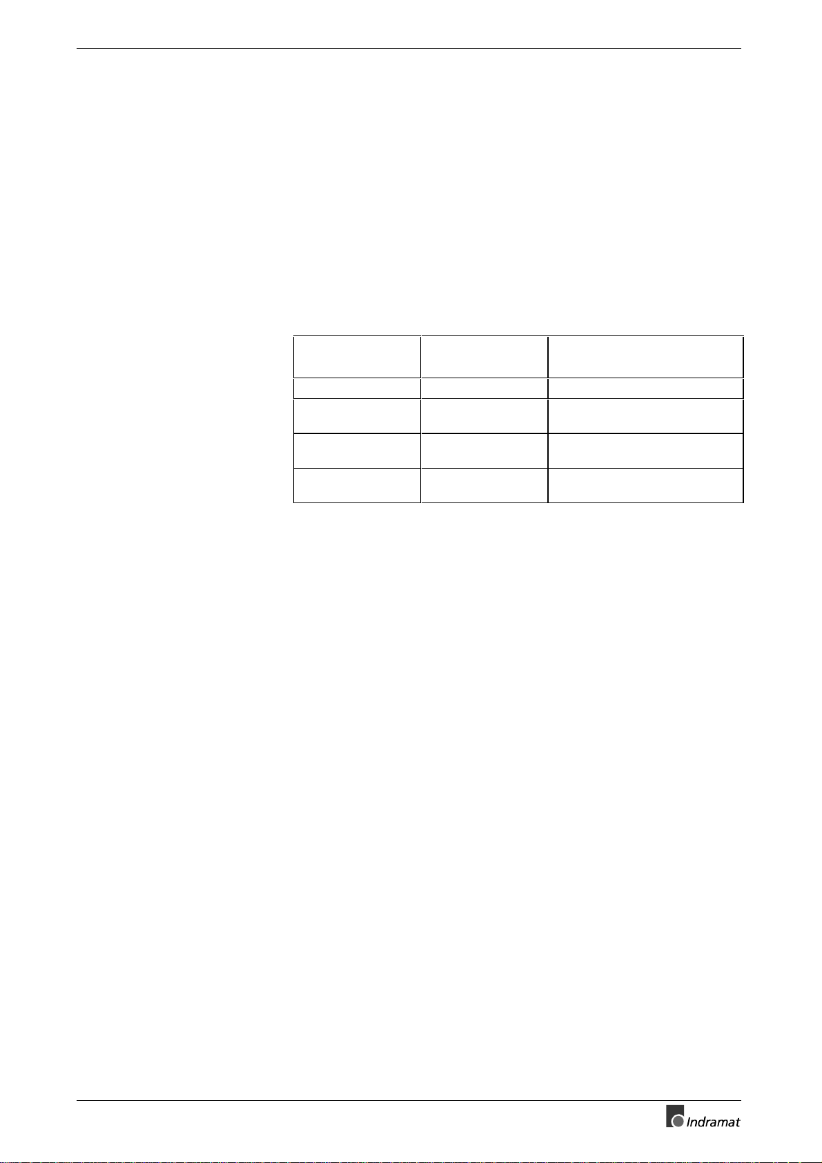
Error Classes
Drive’s Error Reaction
Reset the Error
The errors are separated into f our dif fer ent error c lasses . The err or c lass
is evident from the diagnostic message. They are determined with the
drive’s error response..
Error class : Diagnostic
Message:
Fatal F8xx Torque free switching
Travel range F6xx Velocity command value-zero
Interface F4xx In accordance with best
Non-fatal F2xx In accordance with best
Fig. 3-1: Error Classes and Drive Reaction
If an error state is detected in the drive then an automatic operation of
the drive’s error response will be started as long the drive is in control.
The H1 display blinks a Fx / xx.
The drive’s reaction can be parameterized by P-0-0119, Deceleration as
best as possible, with interface and non-fatal errors. At the end of each
error reaction the drive is switched off.
Errors will not be automatically deleted but must be:
Drive Reaction:
switch
possible deceleration
possible deceleration
•
Reset from the control through the initialization of the command
S-0-0099, Reset Class 1 Diagnostics, or
•
reset by pressing the "S1" button.
If the error state is still present then the error will be immediately detected
again.
A positive edge bit on the control enable signal is necess ary in order to
turn on the drive again.
DOK-ECODR3-SMT-02VRS**-WA01-EN-P
Page 28
3-2 Description of diagnostic letters F... and E... ECODRIVE03 SMT-02VRS
F207 Switching to uninitialized operation mode
Cause:
0 has been selected in at least one of the four mode operating mode
parameters S-0-0032..35. This mode has been selected by the bits 8 and
9 in the master control word while the drive controller was on.
Remedy:
Enter the desired mode in the activated mode parameter.
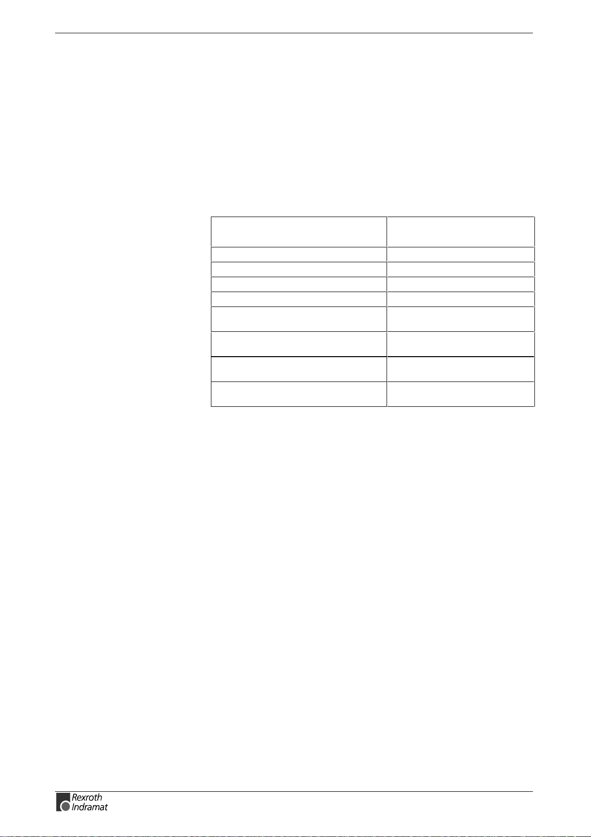
Examples for possible modes are:
Bit list of the mode
Meaning:
Torque control 0000 0000 0000 0001
Velocity control 0000 0000 0000 0010
Position control with act. feedback val. 1 0000 0000 0000 x011
Position control with act. feedback val. 2 0000 0000 0000 x100
Drive-internal interpolation with actual
feedback value 1
Drive-internal interpolation with actual
feedback value 2
Relative drive-internal interpolation with
actual feedback value 1
Relative drive-internal interpolation with
actual feedback value 2
Fig. 3-2: Operation Modes
parameters:
0000 0000 0001 x011
0000 0000 0001 x100
0000 0010 0001 x011
0000 0010 0001 x100
Whic h operation modes can be selected in a ce rtain device is written in
the description for the operation mode parameters:
Parameter: Primary mode of operation S-0-0032
Secondary operation mode 1 S-0-0033
Secondary operation mode 2 S-0-0034
Secondary operation mode 3 S-0-0035
Check for input of the permissible interpolation method.
See also the functional description: "Setting the Operating Mode
Parameters"
F208 UL The motor type has changed.
This indication happens when you power up for the first time with a new
motor.
The regulator settings for the current, velocity and position loops are
stored in the feedback on the motor. After powering up, the drive
compares the motor type stored in the parameter with the connected
motor type. If the two do not match, basic c ontrol loop settings m ust be
adapted, too.
With the Basic Load command, the default control loop settings are
loaded from the feedback memory into the drive. The previous loop
settings are overwritten. By pressing the S1 key, the command Basic
Load is started.
DOK-ECODR3-SMT-02VRS**-WA01-EN-P
Page 29
ECODRIVE03 SMT-02VRS Description of diagnostic letters F... and E... 3-3
Causes:
•
The motor has been exchanged.
•
A parameter file has been loaded, but the parameter S-0-0141, Motor
type contained a motor type different from the present one.
Remedy:
Command C700 Basic Load or press the S1 button.
See also the functional description: "Automatic Execution of the Load
Default Feature".
F209 PL Load parameter default values
After replacing the firmware version, the drive displays “PL”, if the
parameters have been changed in regards to the old product. By
pressing the S1 button on the drive controller or by starting the c ommand
“load basic parameters” , all the parameters will be erased and restored
with the default (initial) values.
Cause:
The firmware has been exchanged; the number of parameters in
comparison to the old product has changed.
Remedy:
Press S1 button on the drive controller, and all the parameters will be
erased and restored with the factory preset default values
•
This overwrites all parameters and positioning blocks.
WARNING
See also the functional description: "Basic parameter block".
F218 Amplifier overtemp. shutdown
The temperature of the amplifier’s heatsink is monitored. If the heatsink
is too hot, the drive will power down in order to protect against damage.
Cause:
1. Ambient temperature is too high. The specified performance
data are valid up to an ambient temperature of 45°C.
2. The amplifier’s heatsink is dirty.
3. Air flow is prevented by other assembly parts or the control
cabinet assembly.
4. Blower defective
5. E219: Sensor defective appears prior to shutdown of unit
DOK-ECODR3-SMT-02VRS**-WA01-EN-P
Page 30

3-4 Description of diagnostic letters F... and E... ECODRIVE03 SMT-02VRS
Remedy:
For 1. Reduce the ambient temperature, e.g. through cooling of the
control cabinet.
For 2. Remove obstructions or dirt from the heatsink.
For 3. Install the device vertically and clear a large enough area for
proper heatsink ventilation.
For 4. Exchange drive.
For 5. Exchange drive.
F219 Motor overtemp. shutdown
The motor temperature has risen to an unacceptable level.
As soon as the temperature error t hreshold of 155°C is exc eeded, the
drive will immediately be brought to a standstill as set in the error reaction
(P-0-0119, best possible standstill).
It applies:
temperature warning threshold
See also E251 Motor overtemperature warning.
Cause:
1. The motor is overloaded. The effective torque demanded from the
motor has been above its allowable continuous torque level for too
long.
2. Wire break, short disconnection or circuit in the motor temperature
monitor line
3. Instability in the velocity loop
Remedy:
For 1. Check the installation of the motor. If the system has been in
operation for a long time, check to see if the the operating
conditions have changed. (in regards to pollution, friction, moved
components, etc.)
For 2. Check wires and cables to the motor temperature monitor for wire
breaks, earth short and short circuits.
For 3. Check velocity loop parameters.
< temperature error threshold
See also the functional descripton: "Temperature Monitoring"
F220 Bleeder overload shutdown
1. The regenerated energy from the mechanism of the machine via the
motor has exceeded the capability of the braking resistor (bleeder). By
exceeding the maxim um energy of the resistor, the drive will shutdown
according to the set error reaction, thereby protecting the bleeder from
temperature damage.
Cause:
The reflected energy from the machine’s mechanism over the motor is
too great.
DOK-ECODR3-SMT-02VRS**-WA01-EN-P
Page 31

ECODRIVE03 SMT-02VRS Description of diagnostic letters F... and E... 3-5
Remedy:
With too much power Å reduce the acceleration value.
With too much energy Å reduce the velocity.
Check the drive installation.
May require installation of an additional bleeder module.
2. The bleeder resistor is used as a charging resistor to load the DC bus
capacitors.
Cause:
If a power failure has been program med as a warning, then the softstart
of the mains section c an be started (controller turned on via the bleeder
resistor on the mains). If the control does not bring the installation to a
standstill once this warning is issued (the drive continues to receive
power from the mains), then the bleeder monitor could be triggered.
Remedy:
•
Set both power failure and undervoltage as a fatal warning. Then the
drive prevents power input from the mains.
•
The control switches the installation/machine off as soon as this
warning is generated.
•
Parametrize undervoltgage as an error, then the drive switches the
machine off with the error reaction which has been set.
See also the functional description: "Current Limit".
F221 Motor temp. surveillance defective
Cause:
Wire break or interruption in the wires for the motor temperature
monitoring.
Remedy:
Check the wiring for the motor temperature monitoring (signals
MT(emp)+ and MT(emp)-) for interruption and short circuit.
See also the functional description: "Temperature Monitoring".
F223 Error during initialisation of the parking axis
Cause:
After the start of com m and S-0-0139, D700 Command Parking axis the
following is deactivated:
• Measuring system monitoring
• control loop monitoring and
• temperature monitoring
DOK-ECODR3-SMT-02VRS**-WA01-EN-P
At the end of the command, measuring system initialization is carried out.
This means all initializations as with command S-0-0128, C200
Communication phase 4 transition check are carried out.
Page 32

3-6 Description of diagnostic letters F... and E... ECODRIVE03 SMT-02VRS
If an error occurs dur ing these initialization procedures, then error F223
Error during initialisation of the parking axis is generated. To specify
the error more precisely, it is necessary to activate the transition
command phase 3 to 4.
Recovery:
1. bring drive into parametrization mode
2. the switching command phase 3 to 4 must be started
3. and the switching command error must be cleared
See also the functional description: "Command Parking Axis"
F224 Maximum braking time exceeded
Cause:
The decel time of the drive is monitored when the drive enable rem oved
and given an error reaction with velocity-controlled standstill of the drive.
If maximum decel time is exceeded (Parameter P-0-0126, Maximum
braking time), then the drive is brought to a torque-free standstill and
error F224 Maximum braking time exceeded is generated.
Remedy:
1. extend P-0-0126, Maximum braking time
2. increase brake ramp of error reaction
P-0-1203, P-0-1201 or P-0-1211 and P-0-1213.
3. reduce external moment of inertia
4. increase torque limit value
See also the function description: "Motor Holding Brake".
F226 Undervoltage in power section
The level of the DC bus voltage is m onitored by the drive contr oller. If the
DC bus voltage falls below a minimal threshold, the drive independently
shuts down according to the set error reaction.
Cause:
1. The power source has been interrupted without first switching off
the drive enable (RF).
2. Disturbance in the power supply
Remedy:
For 1. Check the logic regarding the activation of the drive within the
connected control.
For 2. Check the power supply.
The error can be cleared by removing the drive enable signal.
See also the functional description: "Drive enable"
DOK-ECODR3-SMT-02VRS**-WA01-EN-P
Page 33

ECODRIVE03 SMT-02VRS Description of diagnostic letters F... and E... 3-7
F228 Excessive deviation
When the position loop is closed, the drive monitors whether it is able to
follow the specified com mand value. T his is done by calculating a model
position value in the drive and comparing that value with the actual
feedback value. If the differenc e between theoretical and actual position
value permanently exceeds the value of the S-0-0159, Monitoring
window parameter, the drive obviously cannot follow the given
command value. Then this error is generated.
Cause:
1. The drive’s acceleration capacity has been exceeded.
2. The axis is blocked.
3. Incorrect parameter values set in the drive parameters.
4. Incorrect parameter values in S-0-0159, Monitoring window.
Remedy:
Ref. 1. Check the S-0-0092, Bipolar torque/force limit value
parameter and set it to the maximum permissible value of the
application. Reduce the specified acceleration value from the
controller (see controller Manual).
Ref. 2. Check the mechanical system and eliminate jamming of the axis.
Ref. 3. Check the drive parameters (control loop tuning).
Ref. 4. Set the parameter values of S-0-0159, Monitoring window.
See also the functional description "Position Control Loop Monitoring".
F229 Encoder 1 failure: quadrant error
With wrong signals in the encoder evaluation, a hardware error has been
discovered in the encoder interface 1 being used.
Cause:
1. Defective encoder cable
2. Disruptive electro-magnetic interference on the encoder cable
3. Defective encoder interface
4. Defective drive controller
Remedy:
For 1. Exchange the encoder cable.
For 2. Keep the encoder cable well away from the power cables.
For 3. Exchange the encoder interface.
For 4. Exchange the drive controller.
F230 Max. signal frequency of encoder 1 exceeded
The signal frequency of the encoder 1 (motor encoder) is checked
whether the allowed max. frequency of the encoder interface is
exceeded.
If the frequency is higher than allowed, the error F230, Max. signal
frequency of encoder 1 exceeded is generated. The position s tatus of
the encoder 1 is cleared to 0.
DOK-ECODR3-SMT-02VRS**-WA01-EN-P
Page 34

3-8 Description of diagnostic letters F... and E... ECODRIVE03 SMT-02VRS
Cause:
Maximum speed of the feedback device is lower than the maximum
motor speed.
Suggestion:
•
Don’t allow the motor to run faster than the m axim um allowed s ensor
speed by reducing parameter S-0-0091, Bipolar Speed Limit.
•
Change the sensor for a device with higher speed rating.
F236 Excessive position feedback difference
Cause:
In the communication phase 4 transition check command, position
feedback value 1 and position feedback value 2 are set to the same
value, and the cyclic evaluation of both encoders is started. In cyclic
operation (phase 4), the position feedback dif ferenc e of both encoders is
compared with S-0-0391, Monitoring window feedback 2. If the
amount of the differ ence exceeds the m onitoring window, the error F236
Excessive position feedback difference is diagnosed, the parameterselected error response is performed, and the reference bits of both
encoders are cleared.
Note: The monitoring is off, when the parameter S-0-0391,
Monitoring window feedback 2 is set to the value 0.
Possible Causes :
1. Incorrect parameter for the encoder 2
(S-0-0115, Position feedback 2 type parameter,
S-0-0117, Resolution of feedback 2)
2. Incorrect parameter setting of mechanical system between motor
shaft and encoder 2:
(S-0-0121, Input revolutions of load gear,
S-0-0122, Output revolutions of load gear,
S-0-0123, Feed constant)
3. The mechanical system between motor shaft and encoder 2 is not
rigid (e.g. gear play, slip).
4. Defective encoder cable
5. Maximum input frequency of the encoder interface exceeded
6. Encoder 2 (optional) is not mounted to the driven axis.
7. Incorrect reference measure of an absolute encoder
DOK-ECODR3-SMT-02VRS**-WA01-EN-P
Page 35

ECODRIVE03 SMT-02VRS Description of diagnostic letters F... and E... 3-9
Remedy:
Ref. 1. Check S-0-0115, Position feedback 2 type parameter and
S-0-0117, Resolution of feedback 2.
Ref. 2. Check S-0-0121, S-0-0122, Input/Output revolutions of load
gear and S-0-0123, Feed constant.
Ref. 3. Increase S-0-0391, Monitoring w indow feedback 2; switch off
when using a gearbox with a large amount of slip.
Ref. 4. Replace encoder cable.
Ref. 5. Reduce the velocity.
Ref. 6. Set S-0-0391, Monitoring window feedback 2 to 0 (de-activate
monitoring function).
Ref. 7. Perform P-0-0012, C300 Command ’Set absolute
measurement’.
See also the functional description "Actual Feedback Value Monitoring".
F237 Excessive position command difference
Cause:
When the drive is operating in position control, incoming position
command values are monitored. If the velocity required of the drive by
two successive position com mand values is greater than or equal to the
value in S-0-0091, Bipolar velocity limit value, position command value
monitoring is initiated. The Excessive position command value is
stored in parameter P-0- 0010. The last valid position command value
is stored in parameter P-0-0011.
If position data are to be processed in modulo format, then the
interpretation of the command is also dependent on the value set in
S-0-0393, Command value mode for modulo format. T he parameter
should be set for the "shortest path" (0).
Remedy:
Compare S-0-0091, Bipolar velocity limit value with the velocity in the
program and adjust to match it, if necessary.
F242 Encoder 2 failure: signal amplitude wrong
Cause:
The analog signals of an external measurement system are used for high
resolution analysis of that measurement system. These are monitored
according to two criteria:
1. The pointer length, which is calculated from the amplified sine
and cosine signals, must be at least 1 V.
2. The maxim um pointer length resulting from the s ine and cosine
signals must not exceed 11.8 V.
DOK-ECODR3-SMT-02VRS**-WA01-EN-P
Fig. 3-3: Pointer length
pointer length= sin +cos
22
Page 36
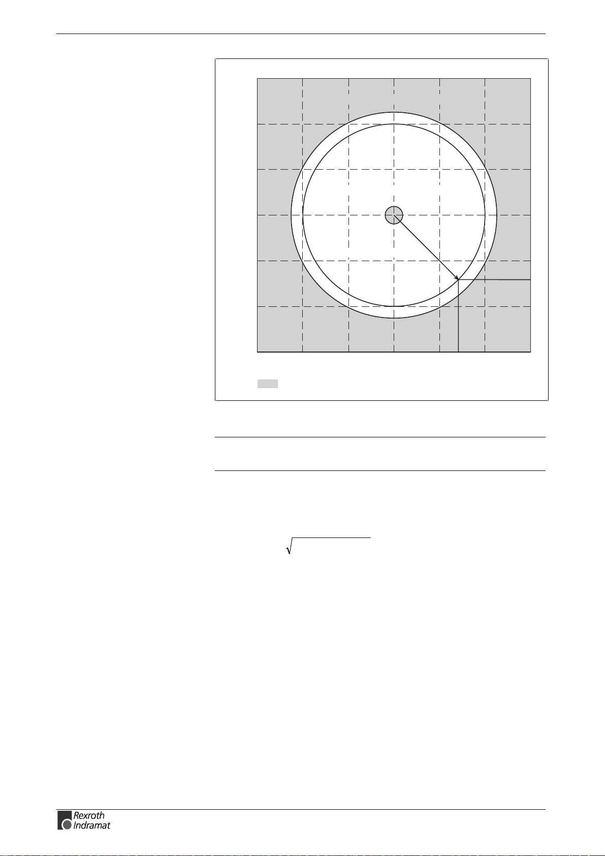
3-10 Description of diagnostic letters F... and E... ECODRIVE03 SMT-02VRS
Permissible signal amplitudes for sine and cosine signals
15
maximum pointer length > 11,8V
10
5
minimum pointer length > 1,0V
0
-5
cosine signal amplitude
-10
-15
-15 -10 -5 0 5 10 15
nominal pointer length (9,2V)
sine signal amplitude
=non-permissible range
Dg5004a1.fh7
Fig. 3-4: Correct signal amplitude
Note: When an incremental encoder with squarewave signals is
used, the signal is not monitored.
Example:
Ucos = -6.5V
Usin = 6.5V
pointer length= - 6.5V + 6.5V »9.2V
()
2
2
Remedy:
1. Check the measurement system cable.
2. Check the measurement system.
F245 Encoder 2 failure: quadrant error
The evaluation of the additional optional encoder (encoder 2) is active. In
the evaluation of the sinusoidal input signals of the optional encoder, a
plausibility check is performed between these signals and the counter fed
by these signals. Doing this, an error has been encountered.
Cause:
1. Defective encoder cable
2. Disruptive electro-magnetic interference on the encoder cable
3. Defective encoder interface
DOK-ECODR3-SMT-02VRS**-WA01-EN-P
Page 37
ECODRIVE03 SMT-02VRS Description of diagnostic letters F... and E... 3-11
Remedy:
For 1. Exchange the encoder cable.
For 2. Keep the encoder cable well away from power cables.
For 3. Exchange the encoder interface (DIAX) or the drive (Ecodrive).
F246 Max signal frequency of encoder 2 exceeded
The signal frequency of the encoder 2 (optional encoder) is checked
whether the allowed max. frequency of the encoder interface is
exceeded.
Whether, in the case of an excessive frequency, the error F246, Max
signal frequency for encoder 2 exceeded is generated or not, depends on
the setting in the parameter P-0-0185, Function of encoder 2. If the
number 4 for spindle encoder is set there, only the position status of the
optional encoder is cleared to 0. In the other c ase, the warning F246 is
generated and the position status is cleared to 0.
F248 Low battery voltage
Cause:
For motors of ser ies MKD and MKE, the absolute position inf ormation is
stored by a battery-powered electronic in the motor feedback. The battery
is designed for a 10-year life span. If the battery voltage falls below 3,1 V,
this message appears. The absolute encoder function will still be
preserved for about 2 weeks.
Malfunction in the control of motors and moving
elements
⇒
CAUTION
Instructions for Exchanging Batteries
Have the following tools and accessories ready:
•
Torx screwdriver size 10
•
Needle-nose pliers, torque wrench
•
New packaged battery (Part No. 257101)
Replace the battery as soon as possible.
Malfunction in the control of motors and moving
elements
DOK-ECODR3-SMT-02VRS**-WA01-EN-P
CAUTION
If the control voltage is turned off while the battery is taken out, the
absolute reference point will be lost. Then, the reference point m ust be
reestablished with the command "Set absolute measuring“.
⇒ Turn off the power supply. Make sure it will not be
turned back on. Exchange the battery while the
control voltage (24V) is turned on.
Page 38

3-12 Description of diagnostic letters F... and E... ECODRIVE03 SMT-02VRS
Removing the Battery
•
Unscrew torx screws with size 10 screwdriver.
•
Pull out the resolver feedback (RSF) lid by hand.
•
Pull off the battery connector.
•
Loosen battery clamp and remove the battery.
•
Place the prepared battery in the housing and screw on the clamp.
Attention! Do not kink or clamp the battery cable.
•
Attach the connector of the battery.
Close the resolver feedback lid, screw in 4 torx screws and tighten to 1.8
Nm with the torque wrench.
F253 Incr. encoder emulator: pulse frequency too high
Cause:
The incremental encoder emulator can process a maximum of 2047 lines
per sample period (500µs ); this value has been exceeded.
Remedy:
1. Reduce the number of lines of the incremental encoder
emulator (P-0-0502).
or
2. Reduce the travel velocity.
See also the functional description: "Encoder Emulation".
F260 Command current limit shutoff
If the current setpoint reaches the peak value, then warning E260
Command current limit shutoff is generated. If the limit remains
standing for more than 1.5 ms, then the drive is shutdown with error
message F260 Command current limit shutoff.
Error cause:
1. Motor power cable has not been connected.
2. Motor holding brake not released (not connected).
3. The axis is mechanically jammed.
4. Accel time exceeds maximum torque greater than 1.5s.
The error message can be switched off in the motor function parameters.
F262 External short at status outputs
Status outputs (ready, warning and UD-message) are m onitored f or s hort
circuits and thermal overload.
• If output current exceeds 350mA for about 1µs, then this is
acknowledged as a short circuit and the pertinent c hannel is shut of f.
The output remains off unit the error is cleared.
DOK-ECODR3-SMT-02VRS**-WA01-EN-P
Page 39

ECODRIVE03 SMT-02VRS Description of diagnostic letters F... and E... 3-13
•
With thermal overload, the error is set and the output(s) shut off. After
the driver has cooled off, the outputs are switched back on and so on.
The error, however, remains until it is cleared. Thermal overload can
occur if several outputs are overloaded in excess of 80 mA.
Note: Light bulbs, for example, c annot be controlled as their inrush
current causes a short-circuit.
Cause:
1. Short circuited outputs
2. One or more outputs are overloaded.
Remedy:
For 1. Eliminate short circuit or limit switching current (< 350 mA)
For 2. Drop current, depending on output, to < 80 mA.
See also the functional description: "Setting the Operating Mode
Parameters".
F267 Erroneous internal hardware synchronization
Cause:
The drive control is synchronized on the bus interface (SERCOS,
Profibus, Interbus, ...). The correct function of the synchronization is
monitored. If the average value of the deviation exceeds 5 µ s, this error
is generated.
Remedy:
Replace drive controller.
F269 Error during release of the motor holding brake
After drive enable is set or while running the brake monitor c om m and the
motor does not move despite that. T he motor torque comm and is equal
to the brake holding torque.
Cause:
1. Motor brake not connected
2. Axis mechanically jammed
3. Frictional torque > brake nominal torque.
Remedy:
on 1. connect brake
on 2. check mechanics and eliminate jam
on 3. switch brake monitor off
DOK-ECODR3-SMT-02VRS**-WA01-EN-P
See also the functional description: "Motor Holding Brake"
Page 40
3-14 Description of diagnostic letters F... and E... ECODRIVE03 SMT-02VRS
F276 Absolute encoder out of allowed window
When turning of f the drive controller with an abs olute encoder , the actual
feedback position will be stored. When powered up, the abs olute pos ition
given by the encoder is compared with the stored position.
Cause:
1. Turning on for the first time (invalid stored position)
2. The motor has been moved further than allowed by the parameter in
the absolute encoder monitoring window, P-0-0097, while it was
turned off.
3. Incorrect position initialization
Remedy:
For 1. Press S1 to reset the error and set the absolute position.
For 2. The motor was moved while turned off and sits outside of its
permissible position. Check to see if the displayed position is
correct in relation to the machine zero point. Reset subsequent
errors.
For 3.
An accident may occur by accidental shaft
movement.
Check absolute position information. The feedback is
defective if the absolute position information is wrong.
WARNING
Note: If a customer password is activated and the dr ive controller is
See also the functional description "Absolute Encoder Monitoring".
The motor should be exc hanged and s ent to the Rex roth
Indramat Customer Service.
locked, then error F276 Absolute encoder out of allowed
window cannot be reset. The drive controller must be unlocked
first.
F277 Current measurement trim wrong
The current reading in the drive controller is compensated for during
operation. The compensation values are stor ed in parameters P-0-4000
and P-0-4001. These values are queried to ensure they maintain the
tolerance of +/- 10 %. Should the values be greater, then this error is
generated.
Cause:
1. Hardware defective in the drive controller.
Remedy:
1. Replace hardware.
DOK-ECODR3-SMT-02VRS**-WA01-EN-P
Page 41

ECODRIVE03 SMT-02VRS Description of diagnostic letters F... and E... 3-15
F281 Mains fault
Cause:
The power supply voltage was not present during operation for at least 3
power periods. As a result, the drive controller was brought to a s tandstill
according to the set error response.
Remedy:
Check the power supply connection according to the project planning
specifications.
F386 No ready signal from supply module
Cause:
Input BbN "mains section ready“ on the drive controller is at 24V, i.e., the
connected mains section is not issuing a ready to operate signal.
Remedy:
1. Check mains section.
2. Check connection from mains section to BbN input on drive.
3. If the drive does not have a separate power section, then switch the
input monitor off.
See also P-0-4062, Monitoring the Mains section
See also the functional description: "Current Limit"
F401 Double MST failure shutdown
The master sync telegram was not r eceived in the drive controller in two
successive SERCOS cycles.
Cause:
1. Disruption in the fiber optic transmission line.
2. Too much attenuation of the light signal.
3. Malfunction in the SERCOS interface (general).
Remedy:
For 1. Check all Fiber Optic connections in the SERCOS ring.
For 2. Measure the attenuation in the fiber optic cable.
The maximum attenuation between TX and RX must not fall
below 12.5 dB.
For 3. Exchange the SERCOS interface module in the drive controller.
See also the functional description: "SERCOS Interface Error"
DOK-ECODR3-SMT-02VRS**-WA01-EN-P
Page 42

3-16 Description of diagnostic letters F... and E... ECODRIVE03 SMT-02VRS
F402 Double MDT failure shutdown
The master data telegram ( MDT ) has not been r eceived in the drive over
the course of two successive SERCOS or fieldbus cycles.
Cause:
1. Fiber optic bus: interference in the fiber optic transmission
2. Fiber optic bus: light signal input power too low
3. SERCOS: problem in SERCOS interface (general)
4. Fieldbus: bus connection terminated/blocked longer than
watchdog duration
5. The bus master is no longer sending cyclic telegrams to the
drive, although they are expected in phase 4.
Remedy:
On 1. All fiber optic cable connections in SERCOS ring must be
checked.
On 2. The fiber optics power read at the receiver (test mode:
continuous light) must lie between the range of –20dBm (10µW )
and –5dBm (320µW). If it does not, then adjust transmission
power or check attenuation of the fiber optic cable (maximum
attenuation between TX and RX may not exceed 12.5 dB!)
On 3. SERCOS interface module in drive has to be replaced.
On 4. Check fieldbus connector and cable connections, signal level.
On 5. Switch master on and start up cyclic communications, see
Control Manual.
See also Function Description: "SERCOS Interface Error"
F403 Invalid communication phase shutdown
An invalid communications phase was given by the SERCOS master
module (phase > 4).
Cause:
Error in the SERCOS master module of the control system.
Remedy:
Consult the control system manufacturer.
See also the functional description: "SERCOS Interface Error"
F404 Error during phase progression
The prescribed order was not maintained during phase progression.
Cause:
Error in the SERCOS master module of the control system.
Remedy:
Consult the control system manufacturer.
See also the functional description: "SERCOS Interface Error"
DOK-ECODR3-SMT-02VRS**-WA01-EN-P
Page 43

ECODRIVE03 SMT-02VRS Description of diagnostic letters F... and E... 3-17
F405 Error during phase regression
Switching back from a communication phase did not switch to phase 0.
Cause:
Malfunction in the SERCOS master module of the controller.
Remedy:
Contact the controller manufacturer.
See also the functional description: "SERCOS Interface Error"
F406 Phase switching without ready signal
The SERCOS master attem pted a phase switch without waiting for the
drive controller’s ready signal.
Cause:
Error in the SERCOS master module of the control system.
Remedy:
Consult the control system manufacturer.
See also the functional description: "SERCOS Interface Error"
F434 Emergency-Stop
Pressing the emergency stop switch (E-Stop) has caused the drive to
perform the em ergency stop function that was selected in the P-0-0119,
Best possible deceleration parameter. Setting bit 15 of S-0-0011,
Class 1 diagnostics causes an error message to be issued to the
controller.
Cause:
The emergency stop switch has been pressed.
Remedy:
Eliminate the malfunction that has caused the emergency switch to be
actuated, and clear the error.
See also the functional description: "Emergency stop feature".
F629 Positive travel limit exceeded
The drive has received a command value which has led to an axis
position outside the positive travel range. The axis has been br ought to a
standstill with the error response "Set velocity command value to zero".
Bit 2 of paramater P-0-0090, Travel limit parameter is set for
"Exceeding travel range is an error", or after exc eeding the position limit
a drive control command has been started (suc h as the drive-controlled
homing procedure).
Cause:
S-0-0049, Positive position limit value exceeded.
DOK-ECODR3-SMT-02VRS**-WA01-EN-P
Page 44

3-18 Description of diagnostic letters F... and E... ECODRIVE03 SMT-02VRS
Remedy:
1. Check S-0-0049, Positive position limit value
2. Check the software limits of the control system
3. Activate the axis after the error response
Procedure:
•
Clear the error.
•
If the power supply was turned off, turn it back on.
•
Move the axis into the permissible working range.
Note: Only command values which lead back into the allowed
working range will be accepted. W ith other comm and values,
the drive will stop again. - The parameter S-0-0057, Pos ition
window defines a tolerance for the travel limits.
See also the functional description: "Axis Limit Values ".
F630 Negative travel limit exceeded
The drive has received a command value which has led to an axis
position outside the negative travel range. The axis has been brought to
a standstill with the error response "Set velocity command value to zero".
Bit 2 of paramater P-0-0090, Travel limit parameter is set for
"Exceeding travel range is an error", or after exc eeding the position limit
a drive control command has been started (suc h as the drive-controlled
homing procedure).
Cause:
S-0-0050, Negative travel limit value exceeded.
Remedy:
1. Check S-0-0050, Negative travel limit value.
2. Check the software limits of the control system.
3. Activate the axis after the error response.
Procedure:
•
Clear the error.
•
If the power supply was turned off, turn it back on.
•
Move the axis into the permissible working range.
Note: Only such command values which lead back into the allowed
working range will be accepted. W ith other comm and values,
the drive will stop again. - The parameter S-0-0057, Pos ition
window defines a tolerance for the travel limits.
See also the functional description: "Travel Range Limits".
DOK-ECODR3-SMT-02VRS**-WA01-EN-P
Page 45

ECODRIVE03 SMT-02VRS Description of diagnostic letters F... and E... 3-19
F634 Emergency-Stop
Pressing the emergency stop (E-Stop) switch has caused the drive to
stop by setting the velocity command value to zero. An error is reported
in the S-0-0011, Class 1 diagnostics parameter.
Cause:
The emergency stop switch has been pressed.
Remedy:
Eliminate the malfunction that has caused the emergency switch to be
actuated, and clear the error.
See also the functional description: "Emergency stop feature".
F643 Positive travel limit switch detected
The positive travel range lim it switch has been activated. The axis was
brought to a standstill with error reaction "Velocity command value to
zero".
In P-0-0090, Travel limit parameter bit 2 has been s et as "travel range
overrun treated as error" or or a drive contr ol com m and was s tarted af ter
the end switch had been actuated (e.g., drive-controlled homing).
Cause:
The positive travel range limit switch has been activated.
Remedy:
1. clear error
2. turn power source back on
3. move axis into the allowed travel range
Note: The drive will not accept command values which lead out of
the permissible travel range. Entering these command values
in the drivecontroller will result in this error.
Also see the function description: "Travel Range Limits".
F644 Negative travel limit switch detected
The negative travel limit switch has been activated. The axis has been
brought to a standstill with the "Set velocity command value to zero" er ro r
response.
Bit 2 of parameter P-0-0090, Travel limit parameter is set for
"Exceeding travel range as error", or a drive control com mand has been
started (such as the drive-controlled homing procedure). with the limit
switch already actuated.
Cause:
The negative travel limit switch has been activated.
Remedy:
1. Reset the error.
2. Turn the power supply on again.
3. Move the axis into the permissible travel range.
DOK-ECODR3-SMT-02VRS**-WA01-EN-P
Page 46

3-20 Description of diagnostic letters F... and E... ECODRIVE03 SMT-02VRS
Note: The drive will not accept command values which lead out of
the permissible travel range. Entering these command values
in the drive controller will result in this error.
See also the functional description: "Travel Range Limits".
F811 Commutation offset could not be determined
The Automatic Commutation Adjustment has tried to determine the
commutation offset. That has failed.
Cause:
The motor could not move freely enough.
Remedy:
Check whether the motor is blocked.
See also the functional description: "Determining commutation offset".
F812 Motion range exceeded during commutation
A range of +/- 1 pole pair distance is defined, within which the axis may
move during the Automatic Commutation adjustment. If this range is
exceeded, this error message appears.
Cause:
1. The drive enable has been set while the axis was still in motion.
2. The axis has been moved by a mechanical force.
3. Parameters P-0-0560 Commutation adjustment current and
P-0-0562 Commutation adjustment periodic time are set too high.
Possibly the mechanical properties of the axis, like f riction or weight
load, have changed.
Remedy:
1. Wait until the axis motion stops and set the drive enable once again.
2. Inhibit the influence of the mechanical force.
3. Reduce the parameter values for P-0- 0560 Comm utation adjus tment
current and P-0-0562 Commutation adjustm ent cycle time. You can
also set them to the default values P-0-0560 Commutation
adjustment current = 25 % and P-0-0562 Com mutation adjus tment
cycle time = 4 milliseconds. Afterwards, start the command D300
Commutation adjustment to evaluate once again the optimal
parameters.
See also the functional description: "Synchronous Motors"
DOK-ECODR3-SMT-02VRS**-WA01-EN-P
Page 47
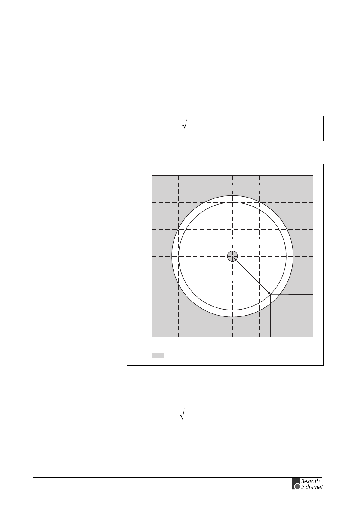
ECODRIVE03 SMT-02VRS Description of diagnostic letters F... and E... 3-21
F822 Encoder 1 failure: signal amplitude wrong
The analog signals of a motor measurement system are used for high
resolution analysis of that measurement system. These are monitored
according to two criteria:
1. The pointer length, which is calculated from the amplified sine
and cosine signals, must be at least 1 V.
2. The maximum pointer length resulting from the sine and cosine
signals must not exceed 11.8 V.
22
cossinlength pointer +=
Fig. 3-5: Pointer length
Permissible signal amplitudes for sine and cosine signals
15
maximum pointer length > 11,8V
10
5
minimum pointer length > 1,0V
0
-5
cosine signal amplitude
-10
-15
-15 -10 -5 0 5 10 15
=non-permissible range
Fig. 3-6: Correct signal amplitude
nominal pointer length (9,2V)
sine signal amplitude
Dg5004a1.fh7
DOK-ECODR3-SMT-02VRS**-WA01-EN-P
Example:
Ucos = -6,5V
Usin = 6,5V
()
2
2
V9.26.5V6.5Vlength pointer
≈+−=
Page 48

3-22 Description of diagnostic letters F... and E... ECODRIVE03 SMT-02VRS
Note: The error cannot be cleared in communications phase 4.
Before clearing the error, switch to communications phase 2.
Note: When an incremental encoder with squarewave signals is
used, the signal is not monitored.
Cause:
1. Defective encoder cable
2. Disruptive electro-magnetic interference on the encoder cable
3. Defective encoder
Remedy:
1. Check the measurement system cable.
2. Lay the feedback cable well away from the motor power cable. The
cover must be placed over the drive controller (see drive controller
project specifications.)
3. Check the measurement system and exchange, if necessary.
F860 Overcurrent: short in power stage
The transistor (IGBT ) current has exceeded the allowed m aximum peak
value. The drive is immediately disabled, the motor freewheels to a stop.
Cause:
1. Short circuit in the motor or motor cable.
2. Defective power section of the drive controller
3. The current regulator was parameterized with wrong values.
Remedy:
For 1. Check the motor cable for a short.
For 2. Exchange the drive controller.
For 3. Check that the current controller parameters are as given in the
motor data sheet; if they differ, input the correct values.
F870 +24Volt DC error
The drive controller requires a 24-V control voltage. T he drive’s torque is
released immediately when the maximum permissible tolerance of
+-20% is exceeded. If an optional electrically released motor holding
brake is present, then it is activated.
Cause:
1. Defective cable for the control voltages.
2. 24-V power supply overload.
3. Defective power supply unit.
4. Short-circuit in the emergency stop circuit.
DOK-ECODR3-SMT-02VRS**-WA01-EN-P
Page 49

ECODRIVE03 SMT-02VRS Description of diagnostic letters F... and E... 3-23
Remedy:
Ref. 1. Check and, if necessary, replace the cable and connections of the
control voltages.
Ref. 2. Check the 24-V power at the power supply unit.
Ref. 3. Check the power supply unit.
Ref. 4. Check the emergency stop circuit for a short-circuit.
Note: This error can only be cleared in parameter m ode (phase 2).
As a result of this error, the encoder emulation is switched off.
F873 Power supply driver stages fault
The voltage supply of the driver stage is m onitored, and if the voltage is
too low, the drive is turned off.
Cause:
The voltage supply of the driver stage is too low.
Remedy:
Exchange drive controller.
F878 Velocity loop error
The velocity loop monitor will appear when the following conditions occ ur
simultaneously:
•
The current command value is at the peak current limit.
•
Command accel and actual velocity have different qualifying signs
•
Actual velocity > 20 rpm or 20 mm/min
•
Command and actual acceleration have different qualifying (+/-)signs.
Cause:
4. Motor cable is connected incorrectly.
5. Defective controller section of the drive
6. Defective feedback
7. Velocity loop paramatrized incorrectly
8. Incorrect commutation offset
Remedy:
For 1. Check the motor cable connection.
For 2. Exchange the drive controller.
For 3. Exchange the motor.
For 4. Check the velocity controller to see whether it is within
operational parameters.
For 5. Exchange the motor.
DOK-ECODR3-SMT-02VRS**-WA01-EN-P
See also the functional description: "Determining the Velocity Controller
Setting".
Page 50

3-24 Description of diagnostic letters F... and E... ECODRIVE03 SMT-02VRS
F879 Velocity limit S-0-0091 exceeded
In torque control, the actual velocity is monitored. This error is generated
if the programm ed velocity in the S-0-0091, Bipolar v elocity limit value
parameter is exceeded by the 1.125-fold value or a m inim um of 100 rpm
(rotary motor) or by 100 mm/min (linear motor).
Cause:
The torque command value was for too long a tim e greater than the load
torque. This causes the actual speed to increase up to the maximum
possible motor speed.
Remedy:
Assign the correct torque com mand value for the required task. Reduce
the S-0-0092, Bipolar torque/force limit value parameter value.
See also the functional description "Limiting to Bipolar Velocity Limit
Value".
DOK-ECODR3-SMT-02VRS**-WA01-EN-P
Page 51
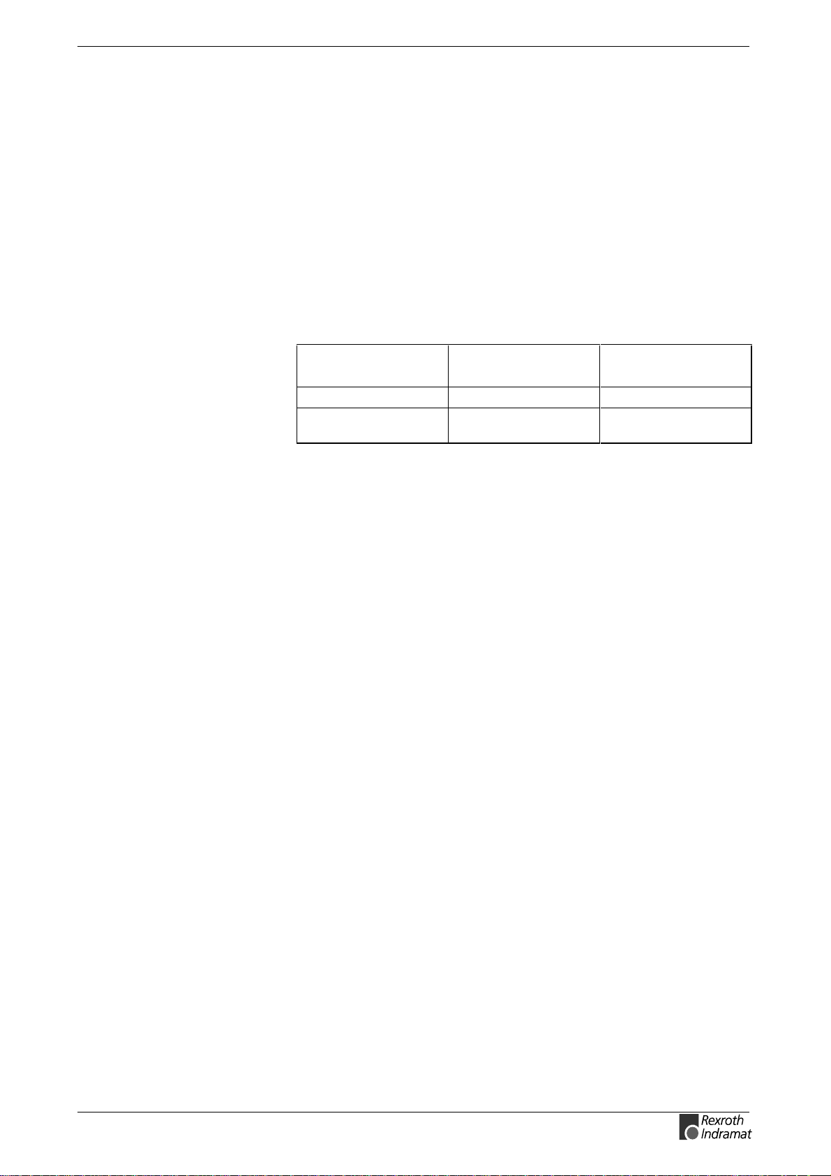
ECODRIVE03 SMT-02VRS Description of diagnostic letters F... and E... 3-25
3.2 Warning diagnostic messages
Warnings do not lead to an
automatic shutdown
The warning class is
evident from the diagnostic
message
Many areas are monitored in connection with operating modes and
parameter settings. As a result, if a state is discovered which is still
allowed by the order of operation, but in continuous operation generates
an error and thereafter leads to shutdown of the dr ive, a warning will be
generated in the case where this state appears again.
Warning Classes
Warnings can be separated into 2 classes. They differentiate if the drive
will perform an automatic response with the appearance of a warning.
Warning Class: Diagnostic
Message:
with Drive Response E8xx Drive Stop
without Drive
Response
Fig. 3-7: Division of the Warning Classes
Warnings can not be externally deleted.
E2xx --
Drive Reaction:
E221 Warning Motor temp. surveillance defective
Temperature monitoring checks to see if the measured motor
temperature is within reasonable bounds. If it determines that it is lower
than -10°C, then it is assumed the m easuring unit is defective. W arning
E221 Warning Motor temp. surveillance defect ive will appear for 30
seconds. Afterwards the drive controller will be brought to a standstill
according to the selected error response and message F221 Error
Motor temp. surveillance defective will be generated.
Cause:
1. Motor temperature sensor not connected.
2. Broken cable.
3. Defective sensor.
4. Broken cable in drive controller.
Remedy:
For 1. Connect the sensor to the drive controller and to the motor
(see project planning specifications for the motor).
For 2. Exchange the wiring between the drive controller and the motor.
For 3. Exchange the motor. Use second sensor in the motor if
available.
For 4. Exchange the drive controller.
DOK-ECODR3-SMT-02VRS**-WA01-EN-P
See also the functional description: "Temperature Monitoring".
Page 52

3-26 Description of diagnostic letters F... and E... ECODRIVE03 SMT-02VRS
E225 Motor overload
The maximum possible motor current is reduced in order to protect the
motor from being destroyed.
If a current flows in the that is greater than 2.2 tim es the m otor current at
standstill S-0-0111, the maximum possible motor current (S-0-0109,
Motor peak current) is reduced. W ith 4-fold motor current at standstill,
the reduction starts after 400 ms. W ith 5-fold cur rent it starts earlier, and
with 3-fold current later.
The E225 Motor overload warning is issued when the motor peak
current is reduced by the limitation.
The reduction also has an effect on the P-0-4045, Active permanent
current.
See also the functional description: "Current Limit"
E226 Undervoltage in power section
If bit 5 of the P-0-0118, Pow er off on error parameter has been set, an
undervoltage condition will be handled as a nonfatal warning. The dr ive
issues this warning if the drive enabling signal is pr esent and the DC bus
voltage message disappears.
Cause:
Power supply unit is switched off or mains failure occurs while the drive
enabling signal is set.
Remedy:
Switch off the drive enabling signal before you switch off the power
supply unit.
E247 Interpolation velocity = 0
The drive-internal position command value interpolator is active if
•
the "drive-internal interpolation" mode
•
the "relative drive-internal interpolation" mode
•
drive-controlled homing
•
Jog
•
drive halt
•
Process block mode
is active
The E247 warning is issued if the employed velocity specification is 0.
Possible velocity specifications are:
• S-0-0259, Positioning velocity
• S-0-0041, Homing velocity
• S-0-0091, Bipolar velocity limit value
• P-0-4030, Jog velocity
• P-0-4007, Process block velocity
DOK-ECODR3-SMT-02VRS**-WA01-EN-P
Page 53

ECODRIVE03 SMT-02VRS Description of diagnostic letters F... and E... 3-27
Note: War ning E247 is suppressed if S-0-0259, Positioning Veloc ity
is cyclically configured.
See also the functional description: "Operating Mode: Drive Internal
Interpolation"
E248 Interpolation acceleration = 0
Cause:
The drive internal position command interpolator (profile generator) is
active. It has been given the acceleration = 0. Without acceler ation, it can
never reach a given speed.
Note: Input parameter values are converted into a drive internal
format, so an input acceleration word > 0 can, when
converted, result in an acceleration = 0. T he param eter values
which, internaly, result in an acceleration > 0, can be
calculated using the formulas found in the chapter entitled
"Drive-internal format of position data"
Operation modes with drive internal position command generation:
1. Drive-internal interpolation
2. Relative drive-internal interpolation
3. Drive-controlled homing
4. Drive Halt
5. Process block mode
6. jog
Remedy:
Input a reasonable value > 0 for the employed acceleration. Possible
acceleration specifications, depending from the operation mode, are:
For 1, 2 and 6: S-0-0260, Positioning acceleration >0
For 3.: S-0-0042, Homing acceleration >0
For 4.: S-0-0138, Bipolar acceleration limit value >0
For 5.: P-0-4008, Process block Acceleration >0
See also the functional description: "Operating Mode: Drive Internal
Interpolation"
E249 Positioning velocity >= S-0-0091
DOK-ECODR3-SMT-02VRS**-WA01-EN-P
Cause:
Operating modes with internal interpolation limit the positioning speed to
that set in S-0-0091, Bipolar velocity limit value.
This applies to the following modes:
1. Drive Internal Interpolation
2. Relative drive-internal interpolation
3. Positioning Block Mode
4. Jogging
Page 54

3-28 Description of diagnostic letters F... and E... ECODRIVE03 SMT-02VRS
Remedy:
S-0-0259, Positioning Velocity or
P-0-4007, Process block velocity or
P-0-4030, Jog velocity
must be reduced
See also functional description: "Operating Mode: Drive Internal
Interpolation".
E250 Drive overtemp. prewarning
The temperature of the heatsink in the drive controller has r eached the
maximum permissible temperature. The drive controller follows the
command value input f or a period of 30 s econds. This mak es it possible
to bring the axis to a standstill with the control system while keeping true
to the process (for example, close the operation, leave the collision ar ea,
etc.).
After 30 seconds, the response set in parameter P-0-0119, Best
possible deceleration will be performed by the drive controller.
Cause:
1. Failure of the drive’s internal blower.
2. Failure of the control cabinet’s climate control.
3. Incorrect control cabinet sizing in regards to
heat dissipation.
Remedy:
For 1. If the blower fails, exchange the drive controller.
For 2. Install climate control feature in the cabinet.
For 3. Check the sizing of the control cabinet.
See also the functional description:"Current Limit"
E251 Motor overtemp. prewarning
As soon as the temperature warning threshold (145°C) is exceeded,
the warning E251 is output, and the drive keeps on following the
command value.
This state can last for a long time without powering down. Only when the
temperature error th reshold is exceeded, an imm ediate powering down
will take place.
See also F219 Motor Overtemperature Shutdown.
Cause:
The motor is overloaded. T he effective torque required from the m otor
was above the allowable standstill continuous torque for too long.
Remedy:
Check the installation of the m otor. For systems which have been in use
for a long time, check to see if the drive conditions have changed (in
regards to pollution, friction, moving components, etc).
See also the functional description: "Temperature Monitoring".
DOK-ECODR3-SMT-02VRS**-WA01-EN-P
Page 55

ECODRIVE03 SMT-02VRS Description of diagnostic letters F... and E... 3-29
E252 Bleeder overload prewarning
Cause:
The braking resistance (bleeder) in the amplifier is charged with the
reflected energy from the motor by about 90%. The bleeder
overtemperature warning shows that an overload of the bleeder is
expected if the feedback energy increases on and on.
Remedy:
Reduce the acceleration value or velocity. Check the drive installation.
E253 Target position out of travel range
In operation modes with drive controlled interpolation, the drive checks
before the move whether the specified S-0-0258, Target position, is
within the possible travel range of the drive. This range is defined by the
parameters S-0-0049, Positive position limit value and S-0-0050,
Negative position limit value. The position limit check is activated in
the parameter S-0-0055, Position polarities with bit 4.
Cause:
The target position lies beyond the position limits, and the position limit
check is activated.. T he motion prof ile results in a target position greater
than the maximum allowed position.
Results:
•
This warning message, E253, appears.
•
The drive stops.
•
The drive does not accept the target position or the process block.
•
In S-0-0012, Class 2 diagnostic warning bit 13 is set.
Remedy:
1. For the Drive controlled interpolation mode, input the S-0-0258,
Target position only within the position limits.
2. Don’t input moves which are greater than the maximum allowed
position minus the current position.
3. In positioning-sequence operating mode always set S-0-4006,
Command Targetposition smaller than the maximum allowed
position.
4. The same holds for Relative Positioning comm ands, where the sum
of the commanded positions + the start pos ition should be less than
the maximum allowed position.
5. Check the position limit values. Moreover, the positive position limit
value must be greater than the negative position limit value.
6. If you don’t need the position limit check, de-activate it, e.g. in
modulo mode.
DOK-ECODR3-SMT-02VRS**-WA01-EN-P
See also the functional description: "Operating Mode: Drive Internal
Interpolation".
Page 56

3-30 Description of diagnostic letters F... and E... ECODRIVE03 SMT-02VRS
E254 Not homed
If absolute positions are selected while in a positioning operation mode,
the control drive must be hom ed to a reference pos ition. If this is not the
case, an absolute position cannot be reached. The drive rejects this
positioning command and stops. The warning E254 will be given.
Cause:
Absolute positioning was selected without the drive being referenced.
Remedies:
1. Do the homing (referencing) command with the drive or
2. do only relative positioning.
See also the function description "Drive-Controlled Homing".
E255 Feedrate-override S-0-0108 = 0
With the param eter S-0-0108, Feedrate override, the travel velocity of
all drive-controlled travel commands can be changed proportionally
(in %).
If the value of this parameter is 0, the travel velocity is also 0. With
velocity = 0, the motor remains st ationary despite having a comm anded
value.
Causes:
1. The parameter S-0-0108, Feedrate override is 0.
2. For devices with analog inputs: Feedrate override via analog input is
activated, and the voltage at the analog input is 0.
3. The feed potentiometer of the connected control system is at 0 or is
being evaluated incorrectly.
Remedies:
For 1.: Set Feedrate override > 0, so that the drive moves. Full speed is
attained with 100% .
For 2.: Apply a voltage > 0 proportional to the desired speed,
+10V corresponds to 100 % (full) speed.
Alternative: De-activate Feedrate override.
For 3.: Turn the feed potentiom eter cautiously, check the analog signal
and the evaluation for it.
See also the functional description: "Sequence control Drive-Controlled
Homing".
DOK-ECODR3-SMT-02VRS**-WA01-EN-P
Page 57

ECODRIVE03 SMT-02VRS Description of diagnostic letters F... and E... 3-31
E256 Torque limit = 0
Cause:
1. For protection against mechanical overload, the maximum torque
can be limited by the S-0-0092, Bipolar Torque Limit parameter.
If the actual value of this parameter is equal to 0, the motor does
not develop torque and does not follow the given command
values.
2. Torque reduction is set via an analog channel, and the applied
voltage amounts to 10 V.
Remedy:
For 1. Set the torque limit to a value greater than 0.
For 2. Establish an analog voltage smaller than 10 V.
See also the functional description:"Current Limit"
E257 Continuous current limit acti ve
The drive controller sets the peak current available for 400 ms.
Thereafter, the continuous current limit becomes active and dynamically
limits the peak current to the continuous current.
Cause:
More continuous torque was required than was available.
Remedy:
1. Check the drive installation.
2. Check the installation of the motor. For systems which have been in
use for a long time, check to see whether the drive conditions have
changed in regards to
•
pollution
•
friction
•
moved masses
See also the functional description: "Current Limit".
E258 Selected process block is not programmed.
Cause:
A positioning block was selected for which ther e is no set target position
or positioning velocity, etc.
Remedy:
Select another positioning block or enter the required data.
DOK-ECODR3-SMT-02VRS**-WA01-EN-P
See also the functional description: "Positioning Block Mode"
Page 58

3-32 Description of diagnostic letters F... and E... ECODRIVE03 SMT-02VRS
E259 Command velocity limit active
In the position control and velocity control operating modes, the ef fective
velocity command value is limited to the value in parameter S-0-0091,
Bipolar velocity limit value. The warning is given if the resulting velocity
command value reaches this limit.
Cause:
Parameter S-0-0091, Bipolar velocity limit value was set too low.
Remedy:
In normal operating conditions, set parameter S-0-0091, Bipolar
velocity limit value to a value 10% greater than the NC maximum
velocity.
See also the functional description: "Limiting to Bipolar Velocity Limit
Value".
E260 Command Current limit active
The warning shows that the speed controller is entering its limit. This
means that the acceleration capacity of the drive has been exceeded. In
position control mode this means that there is an ever-increasing
deviation between command and actual values (lag error).
Remedy:
•
In position control, reduce parametrized accel value or speed value so
that the drive can follow the position command value.
•
Increase torque limit value, if necessary.
E261 Continuous current limit pr ewarning
Digital drives are monitored by a continually operating temperature
model. If the therm al load reaches 100%, the continuous cur rent lim it will
be activated shortly thereafter and error E257 Continuous Current Limit
Active, is displayed.
Before the torque is reduced, a continuous current limit early warning is
given via a switching threshold, which is determined by parameter
P-0-0127, Overload warning.
To deactivate the warning, enter P-0-0127 = 100% into the parameter.
Cause:
The drive controller was overloaded.
Remedy:
1. Check the drive layout.
2. Reduce acceleration.
3. Increase the switching threshold in parameter
P-0-0127, Overload warning
4. With system s which have been used for longer periods of time,
check to see if drive controller conditions have changed
in regards to:
- Friction
- Movements of the load
- Feed during processing.
See also the functional description: "Current Limit"
DOK-ECODR3-SMT-02VRS**-WA01-EN-P
Page 59

ECODRIVE03 SMT-02VRS Description of diagnostic letters F... and E... 3-33
E263 Velocity command value > limit S-0-0091
Cause:
The value given to the drive for S-0-0036, Velocity command value was
greater than permissible.
Remedy:
It is limited to S-0-0091, Bipolar velocity limit value.
See also the functional description: "Operating Mode: Velocity Control"
E264 Target position out of num. range
Cause:
In modes:
•
drive-internal interpolation,
•
relative interpolation and
•
positioning block mode
In drive-internal interpolation mode the previous target position in the
internal position format cannot be reached.
Recover:
1. Check the given target position and correct, if necessary.
2. W ith infinitely turning axes it is necessary that the position data be
illustrated in modulo format.
3. The absolute internally illustrable position can be enlarged by
enlarging the maximum travel range.
E269 Brake torque too low
When switching the drive enable off or with the brake monitoring
command, the motor has m oved while checking the brake torque. The
motor holding brake thus no longer supplies the nominal torque.
Possible causes for the holding torque that is too low:
1. brake is covered with a layer of oxidization due to storage
2. brake is covered with oil or grease
3. brake is worn down
Remedy:
on 1 if the warning occurs when the drive enable is removed, then
on 2 if the warning occurs with the removal of the drive enable, start
on 3 if the brake is repeatedly re-ground yet the torque not achieved,
See also the functional description: "Motor Holding Brake"
start "command brake monitoring".
"command brake monitoring". The command brake monitoring
re-checks the brake torque. If the torque is too low, then the
brake is re-ground. This re-grinding of the brake removes any
residues or films. The brake should then bring its full torque.
then the motor holding brake must be replaced.
DOK-ECODR3-SMT-02VRS**-WA01-EN-P
Page 60

3-34 Description of diagnostic letters F... and E... ECODRIVE03 SMT-02VRS
E281 Mains fault
Cause:
The mains voltage has failed during operation for at least three mains
cycles.
In parameter P-0-0118, Power off on error mains failure and
undervoltage failure have been set as warnings.
The drive does not conduct an error reaction. If the drive continues to
operate despite the warning, an F220 Bleeder overload shutdown
could be generated.
Remedy:
Check the mains connections to ensure that they are as illustrated in the
project planning manual.
See Function Description: "Current Limit".
E386 No ready signal from supply module
Cause:
The input BbN "mains section "ready" to operate“ on the drive controller
is at 24V, i.e., the connected mains section does not issue a ready to
operate.
Mains failure and undervoltage errors have been set in parameter
P-0-0118, Power off on error have been set as warnings.
The drive does not conduct an error reaction. If the drive continues to
operate despite the warning, then error F220 Bleeder overload
shutdown could be generated.
Remedy:
1.) Check mains section.
2.) Check the mains section connection to input ingang BbN on the drive.
3.) If the drive is not supplied by a separate mains section, then the input
of the monitor must be switched off.
See P-0-4062, Power supply monitor
See the Function Description: "Current Limit".
E408 Invalid addressing of MDT-data container A
This warning indicates an error during the index check in the mult iplex
channel. During the cyclical data exchange, the index for the ac cess to
the list S-0-0370, Configuration list for MDT data container is
monitored as to whether it points to a non-initialized field in the list. If it
does, this warning is generated.
E409 Invalid addressing of AT-data container A
This warning indicates an error during the index check in the mult iplex
channel. During the cyclical data exchange, the index for the ac cess to
the list S-0-0371, Configuration list for the AT data container is
monitored as to, whether it points to a non-initialized field in the list. If it
does, this warning is generated.
See also the functional description: "Checking the Indices"
DOK-ECODR3-SMT-02VRS**-WA01-EN-P
Page 61

ECODRIVE03 SMT-02VRS Description of diagnostic letters F... and E... 3-35
E410 Slave not scanned or address 0
While the SERCOS ring is being initialized in com munications phase 1,
each slave which is to participate in the additional phase uptak e m ust be
addressed by the SERCOS master. Slaves which are not addres sed or
which have been set to drive address "0" indicate this by generating
warning E410. Communication with these slaves in higher
communications phases is not possible. They work only in pass through
mode (i.e. they do not have an AT of their own, rther they serve only as a
pass through for the SERCOS communication).
Cause:
The slave was not scanned in phase 1, or address 0 is set.
Remedy:
•
Set the correct slave address.
•
Check the SERCOS master configuration.
See also the functional description: "Adjustments of the SERCOS
Interface"
E825 Overvoltage in power stage
The DC bus voltage is too high.
Cause:
1. During braking (decelerating): the energy regenerated from the
mechanical system via the motor was so high for a moment that it
could not be sufficiently dissipated to heat by the bleeder resistor. The
regenerated current could not be dissipated and therefore charged
the DC bus, so that the voltage has become too high.
2. The mains voltage (AC input) is too high.
Result:
In case of overvoltage, the motor is switched to torque-free operation.
As soon as the DC Bus voltage falls again below the maximum allowable
value, the controller will be turned on again.
Remedy:
For 1. Reduce the acceleration values.
Check the drive controller layout, if necessary.
Install an auxiliary bleeder, if necessary.
For 2. Check the mains supply voltage (AC/3phase).
⇒
Danger of high-voltage shock!
Care for protection against accidental touch.
WARNING
E826 Undervoltage in power section
If the bit 3 is set in the parameter P-0-0118, Power off on error, the
undervoltage is treated as "fatal warning“ with shutdown of the drive
operation. If the drive enable is on at the same time, and the DC bus
voltage indication goes down, the drive displays this warning.
DOK-ECODR3-SMT-02VRS**-WA01-EN-P
Page 62

3-36 Description of diagnostic letters F... and E... ECODRIVE03 SMT-02VRS
Cause:
Switching off the power supply or a loss of m ains while the drive enable
is on.
Remedy:
Switch off the drive enable before switching off the supply unit.
E829 Positive position limit exceeded
The drive has received a command value which resulted in an axis
position outside the positive travel range. The axis has been br ought to a
standstill by setting the velocity command to zero. A clas s 1 diagnostic
error is not generated. The drive will automatically follow command
values that lead back into the allowed range. "Handle travel range
exceeded as warning" is set in bit 2 of parameter P-0-0090, Command
value transmit time (TMTSG).
Cause:
S-0-0049, Positive position limit value exceeded.
Remedy:
Enter command values which lead back into the allowed range.
Note: Only such command values will be accepted that lead back
into the allowed working range. W ith other command values,
the drive will stop again. - The parameter S-0-0057, Pos ition
window defines a tolerance for the travel limits.
See also the functional description: "Travel Range Limits".
E830 Negative position limit exceeded
The drive has received a command value which resulted in an axis
position outside the negative travel range. The axis has been brought to
a standstill by setting the velocity command to zero. A class 1 diagnostic
error is not generated. The drive will automatically follow command
values which lead into the allowed range. "Handle travel range exceeded
as warning" is set in bit 2 of parameter P-0-0090, Travel limit
parameter.
Cause:
S-0-0050, Negative travel limit value exceeded.
Remedy:
Enter command values which lead back into the allowed range.
Note: Only such command values will be accepted that lead back
into the allowed working range. W ith other command values,
the drive will stop again. - The parameter S-0-0057, Pos ition
window defines a tolerance for the travel limits.
See also the functional description: "Travel Range Limits".
DOK-ECODR3-SMT-02VRS**-WA01-EN-P
Page 63

ECODRIVE03 SMT-02VRS Description of diagnostic letters F... and E... 3-37
E831 Position limit reached during jog
If the position limit monitor is activated and the drive is “IN
REFERENCE", then it will be positioned on the position limit during
movement by jogging. If the drive is positioned on the position limit or
beyond the position limit, the drive stops and signals "Position lim it value
reached during jog".
Remedy:
1. Move the motor back within the allowed travel area with the jog
function - or -
2. Turn off the position limit monitor.
See also the functional description: "Operating Mode: Jogging".
E834 Emergency-Stop
Pressing the emergency stop switch has caus ed the drive to per form the
error reaction that had been selected via the P-0-0119, Best possible
deceleration parameter. There is no error message issued to the
controller.
Cause:
The emergency stop switch was pressed.
Remedy:
Eliminate the malfunc tion that led to the activation of the em ergency stop
switch. The warning will then disappear.
See also the functional description: "Emergency stop feature".
E843 Positive limit switch activated
The drive has received a command value which resulted in an axis
position outside the positive travel range. The axis has been br ought to a
standstill by setting the velocity command to zero. A clas s 1 diagnostic
error is not generated. The drive will automatically follow command
values that lead back into the allowed range. Bit 2 of P-0-0090, Travel
limit parameter is set to "Overtravelling is handled as a warning".
Cause:
The positive limit switch has been activated.
Remedy:
Enter command values that lead back into the allowed range.
See also the functional description: "Travel Zone Limit Switch
Monitoring".
DOK-ECODR3-SMT-02VRS**-WA01-EN-P
Page 64

3-38 Description of diagnostic letters F... and E... ECODRIVE03 SMT-02VRS
E844 Negative limit switch activated
The drive has received a command value which resulted in an axis
position outside the negative travel range. The axis has been brought to
a standstill by setting the velocity command to zero. A class 1 diagnostic
error is not generated. The drive will automatically follow command
values that lead back into the allowed range. Bit 2 of P-0-0090, Travel
limit parameter is set to "Overtravelling is handled as a warning".
Cause:
The negative limit switch has been activated.
Remedy:
Enter command values which lead back into the allowed range.
See also the functional description: "Travel Zone Limit Switch
Monitoring".
E881 Mains fault
Cause:
The mains voltage has failed for at least three mains cycles during
operation.
Mains errors and undervoltage errors were set as fatal warnings in
parameter P-0-0118, Power off on error.
The drive switches the motor off.
Recovery:
Checked the mains c onnections to ensure that they are as specified in
the project planning manual.
See function description: "Current Limit".
E886 No ready signal from supply module
Cause:
Input BbN "Mains section readyl“ on the drive controller is at 24V, i.e., the
mains section connected is not issuing a ready to operate signal.
In parameter P-0-0118, Power off on error mains errors and
undervoltage errors were set as warnings.
The drive switches the motor off.
Recovery:
1.) Check mains section.
2.) Check connection from mains section to input BbN on drive.
3.) If the drive is not supplied by a separate mains s ection, then switch
the input monitor off.
See P-0-4062, Power supply monitor.
See function description: "Current Limit".
DOK-ECODR3-SMT-02VRS**-WA01-EN-P
Page 65

ECODRIVE03 SMT-02VRS Description of Diagnostic Letters B..., C..., D... and A... 4-1
4 Description of Diagnostic Letters B..., C..., D... and
A...
4.1 Command Diagnostic Messages B..., C... and D
The commands are used for control of complex features in the drive.
For example, the features "drive controlled homing procedure" or
"Communication Phase 4 Transition Check" are defined as commands.
Commands can start, interrupt or erase a primary control.
A parameter belongs to each command whereby the command can be
controlled by the parameter.
During the command operation, the diagnos tic message "Cx" appears in
the H1 display where the x stands for the number of the command.
It can distinguish between 3 types of commands.
Command Types
•
Drive Commands
- Lead to an eventual automatic drive movement
- Can be started only through an inputted control enable
- Deactivates the active operating mode during its operation
•
Monitor Commands
Activation or deactivation of monitors or features
•
Management Commands
- Lead management tasks that are not interruptible
DOK-ECODR3-SMT-02VRS**-WA01-EN-P
Page 66

4-2 Description of Diagnostic Letters B..., C..., D... and A... ECODRIVE03 SMT-02VRS
B000 Pulse wire/Resolver offset detection
Command P-0-0550, B000 Pulse wire/Resolver offset detection is
conducted.
B001 Motor does not have resolver feedback
If no motor with resolver feedback is connected, then command
P-0-0550, B000 Pulse wire/Resolver offset detection cannot be
conducted.
B002 Drive active at command start
If the drive is in control mode, then it is not possible to c onduct com mand
P-0-0550, B000 Pulse wire/Resolver offset detection . Drive enable is
removed.
B003 Power supply is off
If the power supply is off, then it is not possible to conduct command
P-0-0550, B000 Pulse wire/Resolver offset detection.
B004 S pulse not found within tr avel r a nge
S pulse was not found as pulse wire encoder is defective.
B005 Error writing to feedback EEPROM
An error occurred while writing via the IIC interface.
B006 Error in feedback processor, SDAI does not show 1
The feedback processor does not go into a ready state.
B008 Drive must be in operation mode (phase 4)
The drive is not in Phase 4 (bb).
B009 Drive does not control in secondary operation mode 1
The drive does not accept the internal drive enable.
DOK-ECODR3-SMT-02VRS**-WA01-EN-P
Page 67

ECODRIVE03 SMT-02VRS Description of Diagnostic Letters B..., C..., D... and A... 4-3
B010 5 pulses found, but min. distance to move not reached
Five pulses if travel path is too short, interfer enc e or puls e wire encoder is
defective.
B011 SDAI goes immeadiately back to 0, old PIC version
Signal SDAI goes back to "0", old PIC, setting not possible.
B012 Master password required
No master password has been entered.
B013 Shaft does not turn as expected
The shaft does not turned as planned.
B100 Command Release motor holding brake
The comm and P-0-0542, Command Release motor holding brake has
been activated.
See also the functional description: "Motor Holding Brake".
B101 Command not enabled
The comm and P-0-0542, Command Release motor holding brake has
been activated without prior enabling via the parameter P-0-0538, Bit 8.
See also the functional description: "Motor Holding Brake".
B200 Brake check command
The comm and P-0-0542, Command to open motor holding brake was
activated.
See also the functional description: "Motor Holding Brake"
B201 Brake check only with drive enable
P-0-0541, B200 command brake monitor was activated and the drive
enable was not activated.
See also the functional description: "Motor Holding Brake"
DOK-ECODR3-SMT-02VRS**-WA01-EN-P
Page 68

4-4 Description of Diagnostic Letters B..., C..., D... and A... ECODRIVE03 SMT-02VRS
B202 Error during bedding in the brake
The brake monitor com mand tries to bed in the m otor brake. T his means
that the motor must be moved with closed holding br ake. If the torque of
the motor is too small to move the motor with closed brake, then the
command error is generated.
Cause:
1. Torque of amplifier has been reduced.
2. Axis is mechanically jammed.
3. Weight load plus brake torque is bigger than motor peak torque.
Remedy:
on 1: remove reduction
on 2: eliminate jam
on 3: reduce weight load
See also the functional description: "Motor Holding Brake"
B203 Brake torque too low
The motor m oved when checking the brake torque during the com mand
monitor brake. T he m otor holding brak e thus does not supply the nom inal
torque.
Possible causes for the low holding torque:
4. Brake covered by oxidized layer due to storage
5. Brake covered by oil or lubricant
6. Brake is worn down.
Remedy:
on 1 Re-start "command brake monitor".
on 2 Re-start "comm and brake m onitor". The comm and brak e monitor
on 3 If multiple tries result in the brake still not reaching the holding
See also the functional description: "Motor Holding Brake"
re-checks the brake torque again. If detected that the torque is
too low, then the brake is bedded in. The bedding of the brake
removes the oxidized layer or oil film. The brake s hould now be
able to generate sufficient torque.
torque, then the motor holding brake has to be replaced.
C100 Communication phase 3 transition check
The comm and S-0-0127, C1 Communication phase 3 transition check
has been activated.
See also the functional description: "S-0-0127, C100 Communication
phase 3 transition check"
DOK-ECODR3-SMT-02VRS**-WA01-EN-P
Page 69

ECODRIVE03 SMT-02VRS Description of Diagnostic Letters B..., C..., D... and A... 4-5
C101 Invalid communication parameter (S-0-0021)
Cause:
Communications parameters which are needed to operate the drive in
communication phase 3 are invalid.
Remedy:
A list of the invalid parameters can be s een in parameter S-0-0021, List
of invalid op. data for comm. ph. 2. The invalid parameters must be
rewritten so they are correct.
See also the functional description: "S-0-0127, C100 Communication
phase 3 transition check".
C102 Limit error communication parameter (S-0-0021)
Cause:
Communications parameters, which are needed to operate the drive in
communication phase 3, are outside their limit values.
Remedy:
A list of the invalid parameters can be s een in parameter S-0-0021, List
of invalid op. data for comm. ph. 2. The invalid parameters must be
rewritten with values between the respective min. and the max. value to
be correct.
See also the functional description: "S-0-0127, C100 Communication
phase 3 transition check"
C104 Config. IDN for MDT not confi gur able
Cause:
Telegram type 7 was set in parameter S-0-0015, Telegram type
parameter.
Parameters which are m issing in S- 0-0188, List of configurable data in
MDT are kept in
S-0-0024, Configuration list for the master data telegram.
Remedy:
•
set preferred telegram (telegram type = 0..6 )
•
You must either set a priority telegram (Telegram type = 0..6) or
provide S-0-0024, Config. list of master data telegram with
parameters. These param eter s are als o c ontained in S-0- 0188, List of
configurable data in the MDT.
DOK-ECODR3-SMT-02VRS**-WA01-EN-P
Note: List parameters only allowed in multiplex channel.
See also the function description: "Configuration of Telegram Contents"
Page 70

4-6 Description of Diagnostic Letters B..., C..., D... and A... ECODRIVE03 SMT-02VRS
C105 Configurated length > max. length for MDT
Cause:
Telegram type 7 was set in parameter S-0-0015, Telegram type
parameter.
The length of the configured data in MDT, which is determined by
S-0-0024, Configurations list of the master data telegram,
exceeds the maximum permissible length S-0-0186, Length of the
configurable data record in the MDT.
Remedy:
•
set preferred telegram (telegram type = 0..6 )
•
number of configured parameters in MDT (S-0-0024) must be
decreased
See also the functional description: "Configuration of Telegram Contents"
C106 Config. IDN for AT not confi gurable
Cause:
Telegram type 7 was set in parameter S-0-0015, Telegram type
parameter.
Parameters which are not contained in S-0-0187, List of configurable
data in AT can be seen in
S-0-0016, Custom amplifier telegram configuration list.
Remedy:
•
set preferred telegram (telegram type = 0..6 )
•
S-0-0016, Configuration list of drive telegrams must have
parameters that are also in S-0-0187, List of configurable data in
the AT.
Note: List parameters only allowed in multiplex channel.
See also the function description: "Configuration of Telegram Contents"
C107 Configurated length > max. length for AT
Cause:
Message frame type 7 has been s elected in S-0-0015, Telegram Type
Parameter.
The length of the configured data record in the AT, that is defined via
S-0-0016, Custom amplifier telegram configuration list, exceeds the v
maximum permissible S-0-0185, Length of the configurable data
record in the AT.
Remedy:
• set preferred telegram (telegram type = 0..6 )
• number of configurated parameters in the AT (S-0-0016) must be
decreased
See also the functional description: "Configuration of Telegram Contents"
DOK-ECODR3-SMT-02VRS**-WA01-EN-P
Page 71

ECODRIVE03 SMT-02VRS Description of Diagnostic Letters B..., C..., D... and A... 4-7
C108 Time slot parameter > Sercos cycle time
Cause:
One of the time slot parameters:
•
S-0-0006, AT transmission starting time (T1)
•
S-0-0089, MDT transmission starting time (T2)
•
S-0-0007, Feedback acquisition starting time (T4)
•
S-0-0008, Command valid time (T3)
exceeds S-0-0002, SERCOS Cycle time (Tscyc).
Remedy:
Correct the appropriate parameter(s). T hese tim es are determined by the
manufacturer of the control system and are specified by the SERCOS
interface.
See also the functional description: "Configur ation of the Telegram Send
and Receive Times"
C109 Position of data record in MDT (S-0-0009) even
Cause:
Parameter S-0-0009, Beginning address in master data telegram
contains an even value. This is not permitted.
Remedy:
Parameter S-0-0009, Beginning address in master data telegram must
be set to an odd value. These parameters are determined by the
manufacturer of the control system, and are specified by the SERCOS
interface.
See also the functional description: "Configur ation of the Telegram Send
and Receive Times"
C110 Length of MDT (S-0-0010) odd
Cause:
Parameter S-0-0010, Length of master data telegram contains an odd
value. This is not permitted.
Remedy:
Parameter S-0-0010, Length of master data telegram must be set to an
even value. These parameters are determ ined by the manufac turer of the
control system, and are specified by the SERCOS interface.
DOK-ECODR3-SMT-02VRS**-WA01-EN-P
See also the functional description: "Configur ation of the Telegram Send
and Receive Times"
Page 72

4-8 Description of Diagnostic Letters B..., C..., D... and A... ECODRIVE03 SMT-02VRS
C111 ID9 + Record length - 1 > length MDT (S-0-0010)
Cause:
Parameter(s) are set incorrectly for S-0-0009, Beginning address in
master data telegram and S-0-0010, Length of master data telegram.
The length of the record in MDT f or the drive plus the starting address in
MDT is greater than the total length of the MDT.
Remedy:
The parameters for S-0-0009, Beginning address in master data
telegram and S-0-0010, Length of master data telegram must be
corrected. Those param eters are determined by the manufacturer of the
control system and are specified by the SERCOS interface.
See also the functional description: "Configur ation of the Telegram Send
and Receive Times"
C112 TNcyc (S-0-0001) or TScyc (S-0-0002) error
Cause:
Only 500 µs or even multiples of 1ms are perm itted as valid values for
S-0-0001, NC Cycle time (TNcyc) and S-0-0002, SERCOS Cycle time
(Tscyc). Here, this is not the case.
Remedy:
S-0-0001, NC Cycle time (TNcyc) and S-0-0002, SERCOS Cycle time
(Tscyc) must be corrected. These parameters are determined by the
manufacturer of the control system and are specified by the SERCOS
interface.
See also the functional description: "Configuration of the telegram send
and receive times"
C113 Relation TNcyc (S-0-0001) to TScyc (S-0-0002) error
Cause:
The value of S-0-0001, NC Cycle time (TNcyc) can only be equal to or
be a multiple of S-0-0002, SERCOS Cycle time (Tscyc) . Here this is not
the case.
Remedy:
S-0-0001, NC Cycle time (Tncyc) and S-0-0002, SERCO S Cycle time
(Tscyc) must be corrected. These parameters are determined by the
manufacturer of the control system and are specified by the SERCOS
interface.
See also the functional description: "Configur ation of the Telegram Send
and Receive Times"
DOK-ECODR3-SMT-02VRS**-WA01-EN-P
Page 73

ECODRIVE03 SMT-02VRS Description of Diagnostic Letters B..., C..., D... and A... 4-9
C114 T4 > TScyc (S-0-0002) - T4min (S-0-0005)
Cause:
The maximum permissible value for S-0-0007, Feedback acquisition
starting time (T4) is
S-0-0002, SERCOS Cycle time (Tscyc) -
S-0-0005, Minimum feedback acquisition time(T4min)
The value for S-0-0007, Feedback acquisition starting time (T4) is
incorrect.
Remedy:
Correct S-0-0007, Feedback acquisition starting time (T4). These
parameters are determined by the manufacturer of the control system and
are specified by the SERCOS interface.
See also the functional description: "Configur ation of the Telegram Send
and Receive Times"
C115 T2 too small
Cause:
The value set for S-0-0089, MDT Transmit starting time (T2) is
incorrect. The drive cannot work with this value.
Remedy:
Correct S-0-0089, MDT Transmit starting time (T2).
These parameters are determined by the manufacturer of the control
system, and are specified by the SERCOS interface.
See also the functional description: "Configur ation of the Telegram Send
and Receive Times"
C118 Order of MDT configur ati on wrong
The chronological order of processing the cyclical MDT data in the drive is
the same order in which the configur ated ident numbers (IDN) are placed
in the parameter S-0-0024, Config. list of the master-data-telegram.
For the usage of the multiplex mode in the MDT, there are the parameters
•
S-0-0360, MDT Data container A
•
S-0-0368, Addressing for data container A
•
S-0-0362, List index, MDT data container A
DOK-ECODR3-SMT-02VRS**-WA01-EN-P
If more than one of these parameters is configured in the MDT, their
correct order is checked in the command S-0-0127, C100
Communication phase 3 transition check. The following rules must be
obeyed:
• S-0-0368, Addressing for data container A must be configured as
the first of the 3 parameters above.
• S-0-0360, MDT Dat a container A must be configured as the last of
the 3 parameters above.
If this is not the case, the drive generates the command error C118 Order
of MDT configuration wrong.
Page 74

4-10 Description of Diagnostic Letters B..., C..., D... and A... ECODRIVE03 SMT-02VRS
C200 Communication phase 4 transition check
Meaning:
The command S-0-0128, C200 Communication phase 4 transition
check has been activated.
See also the functional description "S-0-0128, C200 Communication
phase 4 transition check".
C201 Invalid parameter(s) (->S-0-0022)
Cause:
Parameters which will be necessary to operate the drive in
communications phase 4 are invalid. T he invalid parameter s can be s een
in S-0-0022, IDN list of invalid op. data for comm. ph. 3.
Remedy:
The parameters of S-0-0022, IDN list of invalid op. data for comm. ph.
3 must be rewritten so they are correct.
See also the functional description "S-0-0128, C200 Communication
phase 4 transition check".
C202 Parameter limit error (->S-0-0022)
Cause:
Parameters which are necessary to operate the drive in comm unications
phase 4 are outside of their minimum or maximum input values, or the
entered value can’t be processed (for bit bars). T he incorrect param eters
are listed in S-0-0022, IDN list of invalid op. data for comm. ph. 3.
Remedy:
The parameters of S-0-0022, IDN list of invalid op. data for comm. ph.
3 must be rewritten with correct values.
See also the functional description "S-0-0128, C200 Communication
phase 4 transition check".
C203 Parameter calculation error (->S-0-0022)
Cause:
Parameters that are required for phase-4 operation (operating mode)
cannot be processed in that way. The incorrect parameters are listed in
S-0-0022, IDN List of Invalid Op. Data for Comm. Ph. 3.
Remedy:
Write c orrect values to the parameters in S-0-0022, IDN List of Inv alid
Op. Data for Comm. Ph. 3.
See also the functional description "S-0-0128, C200 Communication
phase 4 transition check".
DOK-ECODR3-SMT-02VRS**-WA01-EN-P
Page 75

ECODRIVE03 SMT-02VRS Description of Diagnostic Letters B..., C..., D... and A... 4-11
C204 Motor type P-0-4014 incorrect
An MHD-, MKD or MKE motor (value 1 or 5) is entered into parameter
P-0-4014, Motor type. The appropriate abbreviation "MHD", "MKD", or
"MKE" however, was not found in parameter S-7-0141, Mot or type in the
motor feedback data memory.
Cause:
1. Incorrect parameter set for type of motor.
2. The motor feedback memory cannot be read.
3 motor feedback - not connected
Remedy:
For 1. Enter the type of motor used in parameter P-0-4014, Motor type
For 2. Check feedback connection.
If feedback is defective, exchange motor.
See also the functional description: "Automatic Setting of the Motor Type
for Motors with Feedback Memory".
C210 Feedback 2 required (->S-0-0022)
Cause:
Values that require an optional encoder have been entered in S-0-0147,
Homing parameter or in the S-0-0032...35, Mode of Operation
parameters. However, 0 (not available) has been entered in the P-0-0075,
Interface Feedback 2, optional parameter.
The ident number of the par ameter that requires the optional encoder is
entered in S-0-0022, IDN List of Invalid Op. Data for Comm. Ph. 3.
Remedy:
Modify S-0-0147, Homing parameter or the S-0-0032...35, Mode of
Operation parameters to utilization of the motor encoder instead of
optional encoder or set P-0-0075, Interface Feedback 2, optional to a
value different from 0 to activate the optional measuring system.
See also the functional description "S-0-0128, C200 Communication
phase 4 transition check".
C211 Invalid feedback data (->S-0-0022)
Invalid data has been encountered when the parameters stored in the
motor feedback were read, or an error has occurred when the data was
read.
Causes:
1. Motor feedback cable not connected or defective
2. Motor feedback defective
3. Drive controller defective
Remedy:
Ref. 1. Check motor feedback cable; connect both sides
Ref. 2. Replace motor
Ref. 3. Replace amplifier
DOK-ECODR3-SMT-02VRS**-WA01-EN-P
See also the functional description "S-0-0128, C200 Communication
phase 4 transition check".
Page 76

4-12 Description of Diagnostic Letters B..., C..., D... and A... ECODRIVE03 SMT-02VRS
C212 Invalid amplifier data (->S-0-0022)
During drive initialization, the operating software accesses data from an
EEPROM in the drive controller. This err or message is generated if the
attempt to read the data has failed.
Causes:
Defective hardware in the drive controller.
Remedy:
Replace drive controller.
See also the functional description "S-0-0128, C200 Communication
phase 4 transition check".
C213 Position data scaling error
Cause:
The scaling parameter s for position data permit the position data display
format to be selected. T he drive-internal position data f ormat depends on
the employed motor encoder and the encoder res olution. The f actor used
for converting the position data from the drive-internal format into the
display format or vice versa is outside the allowable range, because either
•
linear motor and rotary position scaling with motor reference, or
•
rotary motor and linear position scaling with motor reference, or
•
linear motor with modulo scaling has been selected; or
•
the determined factor used for converting the position data from the
display format to the internal format, and vice versa, cannot be
represented.
Remedy:
Checking and correcting the relevant parameters, such as
•
S-0-0076, Position data scaling type
•
S-0-0077, Linear position data scaling factor
•
S-0-0078, Linear position data scaling exponent
•
S-0-0079, Rotational position resolution
•
S-0-0116, Resolution of motor feedback
•
S-0-0121, Input revolutions of load gear
•
S-0-0122, Output revolutions of load gear
•
S-0-0123, Feed constant
•
P-0-0074, Interface feedback 1
•
S-0-0277, Position feedback 1 type parameter
See also the functional description "S-0-0128, C200 Communication
phase 4 transition check".
DOK-ECODR3-SMT-02VRS**-WA01-EN-P
Page 77

ECODRIVE03 SMT-02VRS Description of Diagnostic Letters B..., C..., D... and A... 4-13
C214 Velocity data scaling error
Cause:
The scaling parameter s for velocity data permit the velocity data display
format to be selected. T he drive-internal velocity data format depends on
the employed motor encoder and the encoder res olution. The f actor used
for converting the velocity data from the drive-internal format into the
display format or vice versa is outside the allowable range.
Remedy:
Checking and correcting the relevant parameters, such as
•
S-0-0044, Velocity data scaling type
•
S-0-0045, Velocity data scaling factor
•
S-0-0046, Velocity data scaling exponent
•
S-0-0116, Resolution of motor feedback
•
S-0-0121, Input revolutions of load gear
•
S-0-0122, Output revolutions of load gear
•
S-0-0123, Feed constant
•
P-0-0074, Interface feedback 1
•
S-0-0277, Position feedback 1 type parameter
See also the functional description "S-0-0128, C200 Communication
phase 4 transition check".
C215 Acceleration data scaling error
Cause:
The display format of the acceleration data can be set using ac celeration
scaling parameters. The drive-contr olled f ormat of the acceleration data is
dependent on what motor encoder and encoder resolution ar e used. The
factor for converting ac celer ation data f r om internal drive format to dis play
format (or vice-versa) is outside the allowable range.
Remedy:
Check and set the relevant parameters correctly as follows:
•
S-0-0160, Acceleration data scaling type
•
S-0-0161, Acceleration data scaling factor
•
S-0-0162, Acceleration data scaling exponent
•
S-0-0116, Resolution of motor feedback
•
S-0-0121, Input revolutions of load gear
•
S-0-0122, Output revolutions of load gear
• S-0-0123, Feed constant
• P-0-0074, Interface feedback 1
• S-0-0277, Position feedback 1 type parameter
DOK-ECODR3-SMT-02VRS**-WA01-EN-P
See also the functional description "S-0-0128, C200 Communication
phase 4 transition check".
Page 78

4-14 Description of Diagnostic Letters B..., C..., D... and A... ECODRIVE03 SMT-02VRS
C216 Torque/force data scaling error
Cause:
The display format of the torque/f orce data can be set using torque/force
scaling parameters. The factor for converting torque data from drivecontrolled format to dis play format (or vice-ver sa) is outside the allowable
area.
Remedy:
Check and set the relevant parameters correctly as follows:
•
S-0-0086, Torque/force data scaling type
•
S-0-0093, Torque/force data scaling factor
•
S-0-0094, Torque/force data scaling exponent
•
S-0-0110, Amplifier peak current
•
S-0-0111, Motor current at standstill
See also the functional description "S-0-0128, C200 Communication
phase 4 transition check"".
C217 Feedback1 data reading error
All MKD und MHD motors have a data memory in the feedback unit. From
there, settings for the encoder are read.
Cause:
During reading of the values from the feedback, an error has occurred.
Remedy:
Check feedback cable.
Change motor.
See also the functional description "S-0-0128, C200 Communication
phase 4 transition check".
C218 Feedback 2 data reading error
The initialization of the measuring systems is done in the command
S-0-0128, C200 Communication phase 4 transition check. If the
measuring system to initialize has an intrins ic data mem ory, this mem ory
is read.
The error C218 Feedback 2 data reading error is generated, if an
additional optional encoder (encoder 2) is present and being evaluated
(P-0-0075 Feedback 2 type other than 0) and if an error is discovered
while reading the data.
Measuring systems with intrinsic data memory are :
• DSF/HSF/LSF and resolver, as well as
• measuring systems with Endat interface (from Heidenhain)
Cause:
1. Defective measurement system cable
2. Defective measurement system
DOK-ECODR3-SMT-02VRS**-WA01-EN-P
Page 79

ECODRIVE03 SMT-02VRS Description of Diagnostic Letters B..., C..., D... and A... 4-15
Remedy:
For 1. Check the measurement system cable.
For 2. Exchange the measurement system.
See also the functional description "S-0-0128, C200 Communication
phase 4 transition check".
C220 Feedback 1 initializing error
A number of tests are performed when the motor encoder is initialized. An
error was detected during this process. This error may be:
•
Error while reading the angle rectification data
•
Error while copying the angle rectification data
•
Interruption of communication with the encoder
•
Assembly error with the position of an initialization track
•
Error while reading the analog signal of an initialization track
•
Error in the pointer length of the analog signal of an initialization track
•
Invalid offset between the high and low resolution track
•
Error in the measuring system micro-controller
Cause:
1. Defective motor feedback cable
2. Defective motor feedback
3. Defective measurement system interface
Remedy:
For 1. Check the motor feedback cable.
For 2. Exchange the motor.
For 3. Exchange the measuring system interface, if it is a module, or the
complete drive controller.
See also the functional description "S-0-0128, C200 Communication
phase 4 transition check".
C221 Feedback 2 initializing error
Several checks are performed during the initialization of an optional
encoder. An error has been detected during this process . This error m ay
be:
•
Error while reading the angle rectification data
• Error while copying the angle rectification data
• Interruption of communication with the encoder
• Assembly error with the position of an initialization track
• Error while reading the analog signal of an initialization track
• Error in the pointer length of the analog signal of an initialization track
• Invalid offset between the high and low resolution track
• Error in the measuring system micro-controller
• With DAG 1.2: external 24V set for SSI interface
DOK-ECODR3-SMT-02VRS**-WA01-EN-P
Page 80

4-16 Description of Diagnostic Letters B..., C..., D... and A... ECODRIVE03 SMT-02VRS
Cause:
1. External encoder cable defective.
2. Defective feedback.
3. Defective measurement system interface.
Note: If this warning occurs in com bination with an EnDat feedback
device then the feedback device is defective.
Remedy:
For 1. Check the optional feedback cable.
For 2. Exchange feedback.
For 3. Exchange the measuring system interface (module).
See also the functional description "S-0-0128, C200 Communication
phase 4 transition check".
C223 Input value for max. range too high
Cause:
An internal position resolution has been selected via the S-0-0278,
Maximum travel range parameter that no longer guarantees a correct
commutation of the motor.
Remedy:
Select a smaller value for the S-0-0278, Maximum travel range
parameter.
See also the functional description "S-0-0128, C200 Communication
phase 4 transition check".
C227 Modulo range error
Cause:
The marginal conditions for modulo processing were not maintained.
See functional description: "Modulo Processing-Limiting Conditions".
C234 Encoder combination not possible
Cause:
The encoder interface that has been selected in the P-0-0075, Interface
Feedback 2, optional parameter c annot be supported by the drive; it has
already been allocated to the motor encoder.
Remedy:
Select another optional encoder.
See also the functional description: "Determ ining the Encoder Interf ace of
the Optional Encoder"
DOK-ECODR3-SMT-02VRS**-WA01-EN-P
Page 81

ECODRIVE03 SMT-02VRS Description of Diagnostic Letters B..., C..., D... and A... 4-17
C235 Load-side motor encoder wi th inductance motor only
Cause:
The functionality of the optional encoder can be def ined in the P-0-0185,
Function of opt. encoder parameter. If ’load-side motor encoder’ has
been selected as the function of the optional encoder, that function will
only be supported for asynchronous motors.
Remedy:
Set the P-0-4014, Motor type parameter according to the employed
motor type.
Check the P-0-0185, Function of opt. encoder parameter.
See also the functional description: "S-0-0128, C200 Communication
phase 4 transition check".
C236 Feedback 1 required (P-0-0074)
Cause:
A motor encoder is not required (P-0-0074 = 0) if a load-sided motor
encoder has been selected via the P-0-0185, Function of opt. encoder
parameter. However, S-0-0147, Homing parameter or the S-0-0032...35,
Mode of Operation parameters contain values that require a motor
encoder.
Remedy:
Change S-0-0147, Homing parameter or the S-0-0032...35, Mode of
Operation parameters such that they are suitable for using an optional
encoder.
Enter a value ≠ 0 in the P-0-0074, Interface feedback 1 parameter to
activate the motor encoder.
See also the functional description "S-0-0128, C200 Communication
phase 4 transition check".
C238 Wrong function of encoder 2
Cause:
An operating mode needs encoder 2 as control encoder.
Encoder 2 is, however, being used as master ax is encoder or meas uring
wheel encoder.
Recovery:
1. Only operating modes with motor encoder in the operating m ode
parameter S-0-0032, S-0-0033, S-0-0034, S-0-0035, have been
entered.
2. If a mode needs encoder 2 for control, then encoder 2 must be
used as control encoder or spindle encoder. (P-0-0185 =0 or 4).
C300 Command Set absolute measuring
Command P-0-0012, C300 Command ’Set absolute measurement’ was
activated by the control system in use.
See also the functional description: "Setting the Absolute Dimension"
DOK-ECODR3-SMT-02VRS**-WA01-EN-P
Page 82

4-18 Description of Diagnostic Letters B..., C..., D... and A... ECODRIVE03 SMT-02VRS
C302 Absolute measuring system not installed
Command P-0-0012, C300 Command ’Set absolute measurement’ was
started without an absolute measuring system being present.
The command cannot be processed because no absolute measuring
system is available.
Cause:
1. The command should not have been activated.
2. The contacted motor or the external measurement system was
not executed as an absolute encoder.
Remedy:
For 1. Stop execution of the command.
For 2. Equip the motor or external measurement system with an
absolute encoder function.
See also the functional description: "Setting the Absolute Dimension"
C400 Switching to parameter mode
The command for transition into parameter mode. Before editing
parameters that can be edited only in parameter mode, this command
must be processed.
See also the functional description: "Parametrization Mode - Operating
Mode"
C401 Drive active, switching not allowed
Cause:
The comm and C400 Command: Switch to parameter mode has been
started, although the drive enable is on.
Remedy:
End the command and turn off the drive enable, then the com mand can
be started again.
See also the functional description: "Parametrization Mode - Operating
Mode"
C402 Only allowed without master
Cause:
The comm and P-0-4023, C400 Communication phase 2 transition was
started even though the command communications interface (SERCOS
or fieldbus) is active (P-0-4086 = 00b).
The command can only be executed if the command communications
interface (SERCOS or fieldbus ) is inactive (P-0-4086 = xx1b).
The command communications interface is active if
• signals are pending at the SERCOS interface Signal receiver
Remedy:
Phase progression via SERCOS interface must be exec uted or SERCOS
interface deactivated prior to command start.
DOK-ECODR3-SMT-02VRS**-WA01-EN-P
Page 83

ECODRIVE03 SMT-02VRS Description of Diagnostic Letters B..., C..., D... and A... 4-19
C500 Reset class 1 diagnostic, error reset
The command for clearing errors, S-0-0099, C500 Reset class 1
diagnostic was activated by the control system in use. All drive internal
errors are cleared. But before that happens , the cause of the er ror must
have been cleared.
See also the functional description: "Clearing Error"
C600 Drive controlled homing procedure command
Command S-0-0148, C600 Drive controlled homing procedure
command has been activated by the control system in use.
See also the functional description: "Drive-Controlled Homing"
C601 Homing only possible with drive enable
Cause:
The controller enabling signal was not active when the program was
started. This is not permitted.
Remedy:
1. Switch on the controller enable signal.
2. Start the command again.
See also the functional description: "Functions of the Control During
Drive-Controlled Homing"
C602 Distance home switch - reference mark erroneous
Cause:
The evaluation of the homing switch has been activated. The distance
between the positive homing switch edge and the reference mark that
shall be interpreted is outside the valid range.
Remedy:
Read the value from the S-0- 0298, Reference cam shift by ... param eter
and enter it in the S-0-0299, Home switch offset parameter.
See also the functional description: "Connection of the Home switch"
C604 Homing of absolute encoder not possible
Cause:
If, with absolute encoder, the homing command was called without having
done the command P-0-0012, Set absolute measuring before, the
homing command is cancelled with this error.
If the encoder had been referenced with the " Set absolute measuring“,
then the homing command would give you a possibility to trigger a
positioning move to the reference point.
DOK-ECODR3-SMT-02VRS**-WA01-EN-P
Page 84

4-20 Description of Diagnostic Letters B..., C..., D... and A... ECODRIVE03 SMT-02VRS
Remedy:
Home the absolute encoder with the command "Set absolute
measuring“.
See also the functional description: "Possible Error Messages During
Drive-Controlled Homing"
C606 Reference mark not detected
Cause:
If
•
a distance-coded or
•
an incremental measuring system with zero switch
are referenced, then the max imum travel distanc e during the referencing
procedure is known. If no reference mark is detected over the course of
this path, then error message C606, Reference mark not detected is
generated and referencing is aborted with the generation of an error.
C700 Basic load
Note: The traversing path of linear non-distance coded measuring
system with zero switch evaluation is not known if „0“ is
entered in parameter P-0-0153, Optimal distance home
switch - reference mark. This is generally the case if the
linear scale has no reference marks at equal and known
distances.
Remedy:
•
Check the measuring system to be referenced as well as all cabling.
•
Check for correct parametrization.
•
Check the correction reference mark detection using command
P-0-0014, D500 Command determine marker position
With m otors of the MHD, MKD and MKE series, the controller par am eters
for the connected motor that are stored in the controller are set to their
default values by activating the controller parameters that are stored in
the motor feedback. The drive controller issues the C7 message to
indicate that the C700 Basic load comm and has been activated via the
command parameter S-0-0262, C700 Command basic load.
Cause:
The command C700 Basic load has been activated.
See also the functional description "Load Default"
DOK-ECODR3-SMT-02VRS**-WA01-EN-P
Page 85

ECODRIVE03 SMT-02VRS Description of Diagnostic Letters B..., C..., D... and A... 4-21
C702 Default parameters not available
With motors of the MHD, MKD and MKE series, adapting the control
loops to the connected digital drive is done by activating the speed
controller parameters that are stored in the motor feedback. The drive
controller employs the C702 Default parameters not available m essage
to signal that the S-0-0262, C700 Command basic load command has
been activated, but that there is no data memory at the connected motor.
Remedy:
Order the parameter sheet of the em ployed motor from the INDRAMAT
Service, and enter the parameters.
See also the functional description: "Error Conditions of the Load Def ault
Settings Procedure"
C703 Default parameters invalid
Cause:
The default parameter s are read from the motor feedback data mem ory.
At least one of these parameters is invalid.
Remedy:
Check the connection to the motor feedback. Exchange the motor if
necessary.
See also the functional description: "Error Conditions of the Load Def ault
Settings Procedure"
C704 Parameters not copyable
Cause:
The default parameters in use are not compatible with this software
version.
Remedy:
Please contact Indramat. Explain, which software version, which device
and which motor type you have.
See also the functional description: "Error Conditions of the Load Def ault
Settings Procedure"
C800 Default parameter load
How to start the command:
This command can be started in 2 ways:
1. When "PL" is displayed on the drive controller (appears after a change
in firmware version), by pressing the S1 button beneath the display.
2. By starting the P-0-4094, C8 Default parameter load
What the command does:
All the parameters are cleared and preset with their default (initial) value.
Process blocks and control loop settings are overwritten, too.
DOK-ECODR3-SMT-02VRS**-WA01-EN-P
Page 86

4-22 Description of Diagnostic Letters B..., C..., D... and A... ECODRIVE03 SMT-02VRS
Default parameters:
Default values are stored in the drive f or all par ameters which are lis ted in
S-0-0192, IDN-list of backup operation data. They define a basic state
of the drive that permits the drive to be switched "ready for operation"
(display "bb“). Mechanical components like gear and load as well as the
control loop settings therefore are not taken into consideration.
See also the functional description: "Basic parameter block".
C801 Parameter default value erroneous (-> S-0-0021)
Cause:
During the execution of P-0-4094, C800 Command Base-parameter
load, a default value that has been stored in the drive was recognized as
incorrect. The related param eter is entered in the S-0-0021, IDN-list of
invalid op. data for comm. Ph. 2.
See also the functional description: "Basic parameter block"
C802 Locked with password
The parameter S-0- 0267, Password offers the possibility to set a write
protection for the drive parameters. The diagnostic message C705
Locked with password indicates, that the command P-0-4094, C800
Command Base-parameter load has been started, although the drive
parameters are protected with the customer password.
See also the functional description: "Basic parameter block"
C900 Position spindle command
The command S-0-0152, C900 Position spindle command has been
activated via the applied control.
See also the functional descriprion: "Spindle Positioning".
C902 Spindle positioning requires drive enable
Cause:
When st arting the S-0-0152, C900 Position spindle command, the drive
enable was not yet set.
Remedy:
Set the drive enable before starting the command.
C905 Positioning wi th non-init. absolute encoder impossible
When using an absolute encoder as motor or spindle feedback, the
command "set abs olute measure" must be perf ormed in order to set the
position reference between spindle and measurement system.
DOK-ECODR3-SMT-02VRS**-WA01-EN-P
Page 87

ECODRIVE03 SMT-02VRS Description of Diagnostic Letters B..., C..., D... and A... 4-23
Cause:
The absolute encoder used as motor or spindle feedback is not in
reference with the spindle. The command S-0-0152 Drive controlled
spindle positioning cannot be executed, because the measuring system
doesn’t have a reference position.
Remedy:
•
If an absolute encoder is not desired: switch off the absolute encoder
evaluation in parameter S-0-0277, Position feedback 1 type or
S-0-0115, Position feedback 2 type.
•
Do the P-0-0012, C300 Command ’Set absolute measurement’.
See also the functional description: "Drive-Controlled Homing" and
"Setting the Absolute Dimension".
C906 Error during search for zero pulse
Cause:
The homing procedure within the spindle positioning has not been
executed successfully. The encoder zero pulse has not been found or
could not be assigned properly.
Remedy:
•
Check the parametrization of spindle positioning, especially the used
combination of encoder and reference (home) switch.
•
Check the encoder parametrization.
•
Check the distance between zero pulse and reference switch.
•
Do the drive controlled homing to check the homing procedure.
D300 Command adjust commutation
A correctly adjusted comm utation offset is mandatory for the operation of
synchronous motors. The "D3“ mes sage indicates that the com mand has
been activated, that is used for determining the commutation offset.
Cause:
The commutation setting command has been activated.
See also the functional description: "Determining commutation offset"
D301 Drive not ready for commutation command
Meaning:
The drive must be in torque control mode when the "D3“ command is
started.
Cause:
Activate torque control and start the command again.
See also the functional description: "Determining commutation offset"
DOK-ECODR3-SMT-02VRS**-WA01-EN-P
Page 88

4-24 Description of Diagnostic Letters B..., C..., D... and A... ECODRIVE03 SMT-02VRS
D302 Torque/Force too small to move
The comm and D3 Command adjust commutation has been star ted. To
perform this, the motor must move. But it doesn’t move.
Cause:
1. T he torque is too small to overcom e mechanical resistanc es (friction
or weight).
2. The motor is blocked mechanically.
3. Motor movement and encoder rotation direction are contradictory to
each other.
Remedy:
1. Increase the S-0-0092, Torque/Force limit bipolar so that the m otor
overcomes the mechanical resistances and can turn. Check also
P-0-0109, Torque/Force peak lim it; this parameter value should be at
least as great as S-0-0092.
2. Clear the jamming. Check also the brake.
3. At the motor connection, switch 2 phases or turn rotational direction of
encoder ( Parameter S-0-0277, position encoder type parameter 1 ).
Note: For devices with analog inputs, the torque can be limited via
an analog torque reduction.
See also the functional description: "Determining commutation offset"
D303 Drive in control at start of command
If the drive controller is in control, then it is not possible to execute
command P-0-0524, D300 Commutation adjustment command.
D306 Power is off
If the power is off, then it is not poss ible to execute com mand P-0-0524,
D300 Commutation adjustment command.
D307 Drive does not move
Command P-0-0524, D300 Commutation adjustment command was
terminated with an error.
D308 No adjustment with asynchronous motor
Commutation offset determination is not possible with an asynchronous
motor.
DOK-ECODR3-SMT-02VRS**-WA01-EN-P
Page 89

ECODRIVE03 SMT-02VRS Description of Diagnostic Letters B..., C..., D... and A... 4-25
D309 Proceed to phase 4
If the drive controller is not in phase 4 (bb), then it is not possible to
executed command P-0-0524, D300 Commutation adjustment
command.
D310 Input master password
No master password was input.
D311 Commutation offset could not be determined.
The Automatic Commutation Adjustment has tried to determine the
commutation offset. That has failed.
Cause:
The motor could not move freely enough.
Remedy:
Check whether the motor is blocked.
See also the functional description: "Determining commutation offset"
D312 Motion range exceeded during commutation
A range of +/- 1 pole pair distance is def ined, within which the axis may
move during the Automatic Commutation adjustment. If this range is
exceeded, this error message appears.
Cause:
1. The drive enable has been set while the axis was still in motion.
2. The axis has been moved by a mechanical force.
3. Parameters P-0-0560 Comm utation adj ustm ent current and P-0-0562
Commutation adjustment cycle time are set too high. Possibly the
mechanical properties of the axis, like friction or weight load, have
changed.
Remedy:
1. Wait until the axis stands still and set the drive enable once again.
2. Inhibit the influence of the mechanical force.
3. Reduce the parameter values f or P-0-0560 Comm utation adjustment
current and P-0-0562 Commutation adjustm ent cycle time. You can
also set them to the default values P-0-0560 Commutation
adjustment current = 25 % and P-0-0562 Commutation adjustment
cycle time = 4 milliseconds. Afterwards, start the command D300
commutation adjustment to evaluate once again the optimal
parameters.
DOK-ECODR3-SMT-02VRS**-WA01-EN-P
See also the functional description: "Synchronous Motors".
Page 90

4-26 Description of Diagnostic Letters B..., C..., D... and A... ECODRIVE03 SMT-02VRS
D400 Positive stop drive procedure command
When the positive stop drive procedure command is activated, all
controller monitoring which would result in an er ror message for c lass 1
diagnostic caused by blocking the drive with a positive stop is turned off.
Cause:
Command D400 Positive stop drive procedure command was
activated.
See also the functional description: "Positive stop drive procedure"
D401 ZKL1-Error at command start
Cause:
A class 1 diagnostic error was discovered while starting the command
"Positive stop drive procedure" As a result, the command could not be
executed.
Remedy:
Eliminate the cause of the error , clear the error, and s tart the command
again.
See also the functional description: "Positive stop drive procedure"
D500 Command Get mark position
The P-0-0014, D500 Command determine marker position command
can be used for checking the correct acquisition and position of the
reference mark er of an incremental measur ing system. The "d5“ display
shows that the command has been activated.
Cause:
The Determine marker position command has been activated.
See also the functional description: "Functional principle of command
detect marker position"
D501 Incremental encoder required
Cause:
The command has been started for a measuring system that does not
possess real reference m arkers. Thes e include measuring systems s uch
as DSF, EnDat, SSI or resolver measuring systems.
Remedy:
Check whether the correct encoder has been selected in S-0-0147,
Homing parameter.
Employ an encoder system with real reference markers.
See also the functional description: "Functional principle of command
detect marker position""
DOK-ECODR3-SMT-02VRS**-WA01-EN-P
Page 91

ECODRIVE03 SMT-02VRS Description of Diagnostic Letters B..., C..., D... and A... 4-27
D600 Cancel reference point procedure command
Meaning:
The reference of the encoder that has been selected via S-0-0147,
Homing parameter is canceled.
Cause:
The D600 Cancel reference point procedure command has been
activated.
See also the functional description: "Drive-Controlled Homing"
D700 Parking axis command
The command permits one or more drives of a drive package to be
stopped without error messages being issued to the controller and/or the
power supply module. The remaining drives of the package can be
handled without any restrictions.
Cause:
The S-0-0139, D700 Command parking axis command has been
activated.
See also the functional description: "Command Parking Axis"
D701 Parking axis only while drive is disabled
The start of com mand "Com m and Parking Axis" is only permitted without
drive enable applied.
If the comm and is activated with an applied drive enable, then the drive
generates command error D701 Parking axis only while drive is
disabled.
See also the functional description: "Command Parking Axis"
DOK-ECODR3-SMT-02VRS**-WA01-EN-P
Page 92
4-28 Description of Diagnostic Letters B..., C..., D... and A... ECODRIVE03 SMT-02VRS
D900 Command automatic loop tuning
Description:
The start of this command means that an automatic control loop setting is
executed in the drive if the drive is in the loop at com mand start, i.e., the
drive enable signal is applied.
See also Function description "Automatic Control Loop Settings"
The start of this command can trigger a movement if
drive enable and drive start are at the drive.
The drive conducts autonomous movements within the
range defined by both limits.
The E-stop sequence function and the travel range limit
switch must be guaranteed and checked.
WARNING
D901 Start requires drive enable
Description:
To ensure that the drive is in the loop when starting the command
P-0-0162, D9 automatic control loop setting, such is queried at
command start.
Cause:
Drive enable not set at command start (NO-RF)
Remedy:
Set drive enable and restart command.
See also the functional description: "Automatic Control Loop Settings"
See also Function description:
"Safety Instructions for Electric Servo Drives and
Controls"
During command D9, the drive autonomously conducts
motions, i.e., without external command value.
D902 Motor feedback data not valid
Description:
At the start of the automatic control loop setting (P-0-0162), the motor
parameters
• torque constant
• rated current of unit are read out of the feedback.
Cause:
• One of the above feedback data has a value s maller than or equal to
zero (<=0). This means that the controller parameter is incorrectly
calculated.
• Motor without feedback data storage.
DOK-ECODR3-SMT-02VRS**-WA01-EN-P
Page 93

ECODRIVE03 SMT-02VRS Description of Diagnostic Letters B..., C..., D... and A... 4-29
Remedy:
If known, write the correct values back into the parameter or contact
Indramat Customer Service to obtain the feedback data valid for your
motor.
In the worst case, it may be necessary to replace the motor.
See also the functional description: "Automatic Control Loop Settings"
D903 Inertia detection failed
Description:
At the start of the automatic control loop setting, the load moment of
inertia is determined with an "oscillation attempt".
This means that the speed change and the m otor current m ust exceed a
minimum value during acceleration or deceleration to guarantee a
sensible and sufficiently precise calculation of the moment of inertia.
Cause:
•
drive acceleration too low
•
number of measured value too small for automatic control loop setting
•
motor speed too low
•
load moment of inertia too big
Remedy:
•
increase bipolar torque/force value S-0-0092
•
increase pos. accel S-0-0260
•
increase pos. speed S-0-0259
•
increase feedrate override S-0-0108
See also Function description: "Prerequisites for starting the automatic
control loop settings"
D904 Gain adjustment failed
Description:
In exceptional cases, difficulties in the automatic control loop s etting may
arise. This means that an automatic setting is not pos sible. Standard or
default values must therefore be loaded into the drive.
Cause:
•
oscillating mechanical systems (resonance)
•
high level of interference in the encoder signal
Remedy:
Satisfactory results can som etimes be ac hieved by starting the com mand
P-0-0162, D9 automatic control loop setting with a large P-0-0163,
damping factor for automatic control loop setting, i.e., low dynamics.
This value can be reduced until the control loop behaves as needed.
If even then control loop settings remain unsuccessful, then the setting
must be manual.
See also the functional description:"Automatic Control Loop Settings"
DOK-ECODR3-SMT-02VRS**-WA01-EN-P
Page 94

4-30 Description of Diagnostic Letters B..., C..., D... and A... ECODRIVE03 SMT-02VRS
D905 Travel range invalid, P-0-0166 & P-0-0167
Description:
Before starting an automatic control loop setting, both tr avel range limits,
i.e., upper and lower, must be defined.
When st arting command P-0-0162, D9 automatic control loop setting
the number values are automatically checked f or validity. It is checked if
the traversing path is large enough and if sensible values have been
entered.
Cause:
•
P-0-0167, upper traversing range smaller than P-0-0166, lower
traversing range
•
Maximum traversing path (P-0-0169, Travel distance for autom.
control loop adjust) is less than 6 motor rotations and thus too small
to start the automatic control loop setting.
Remedy:
•
clear command error by ending the command
•
a) input new limits whereby:upper > lower limits
b) redefine limits to define a larger traversing range
•
restart command with sensible traversing range
See also Function description: "Prerequisites for starting the automatic
control loop settings""
D906 Travel range exceeded
Description:
During automatic control loop setting, there is a constant monitoring of the
valid traversing range P-0-0166 and P-0-0167.
Cause:
If only one of these limits is exceeded, then command error D906 is
generated and the drive brought to standstill speed controlled.
Possible causes:
•
actual position outside of defined traversing range
•
limits redefined after command start
Remedy:
•
clear command error and end command
•
redefine limits so that the actual position is within defined traversing
range
•
retart command using sensible traversing range
See also Function description: "Prerequisites for starting the automatic
control loop settings"
DOK-ECODR3-SMT-02VRS**-WA01-EN-P
Page 95

ECODRIVE03 SMT-02VRS Description of Diagnostic Letters B..., C..., D... and A... 4-31
4.2 Status diagnostic messages
A000 Communication phase 0
The comm unication process is divided into f our communication phases:
Phases 0 and 1 are used to recognize the participants. Phase 2 is used to
prepare the time and data protocols for communication phases 3 and 4.
Initialization is performed in ascending order of the sequence. The
defaults of the communication phase are set by the control system. When
the switch to communication phase 4 takes place, initialization is
completed and input power is enabled.
If the phase switch is interrupted, the status display remains in the
communications phase which has already been reached.
If diagnostic mess age A000 Communication phase 0 is active, the drive
is in phase 0 and is waiting for a phase transfer to 1 by the control
system.
See also the functional description: "Parametrization Mode - Operating
Mode".
A001 Communication phase 1
The comm unication process is divided into f our communication phases:
Phases 0 and 1 are used to recognize the participants. Phase 2 is used to
prepare the time and data protocols for communication phases 3 and 4.
Initialization is performed in ascending order of the sequence. The
defaults of the communications phase are set by the control system.
When the s witch to communications phas e 4 takes place, initialization is
completed and input power is enabled.
If the delayed phase switch is interrupted, the status display remains in
the communications phase which has already been reached.
If diagnostic mess age A001 Communication phase 1 is active, the drive
is in phase 1, and transfer from phase 1 to 2 has not yet been initiated by
the control system.
See also the functional description: "Parametrization Mode - Operating
Mode".
A002 Communication phase 2
For field bus and SERCOS devices, the control dem ands via the master
communic ation "com munica tion phase 2", or the drive has been s witched
to phase 2 by the command P-0-4023, C400 Communication phase 2
transition. Therefore, the drive is in the "param eter m ode". In this mode,
many parameters are editable, which can no more be edited in
"communication phase 4" ("operation mode").
In this phase, usually
• for field bus and SERCOS devices, the communication parameters
are transferred from the control to the drive and
• the functions Load and Save parameters ("file services“) are
performed when needed.
DOK-ECODR3-SMT-02VRS**-WA01-EN-P
Page 96

4-32 Description of Diagnostic Letters B..., C..., D... and A... ECODRIVE03 SMT-02VRS
Before switching to communication phase 3 is possible, the command
S-0-0127, C100 Communication phase 3 transition check must be
done. In this command, the drive checks e.g. the validity of the
parameters needed for the communication phase 3.
After successf ul ex ecution of the command, the c ontrol switches the drive
to comm. phase 3 (with field bus and SERCOS devices), or the drive
switches by itself to phase 3 at the end of the command.
See also the functional description: "Parametrization Mode - Operating
Mode".
A003 Communication phase 3
For field bus and SERCOS devices, the control dem ands via the master
communic ation "com munica tion phase 3", or the drive has been s witched
to phase 3 by the command S-0-0127, C100 Communication phase 3
transition check. The drive is in the "restric ted parameter m ode". In this
mode, still many parameters are editable too, which can no more be
edited in "communication phase 4" ("operation mode").
A010 Drive HALT
Before switching to communication phase 4 is possible, the command
S-0-0128, C200 Communication phase 4 transition check must be
done. In this command, the drive checks e.g. the validity of the
parameters needed for the communication phase 4 ("operation mode").
After successf ul ex ecution of the command, the c ontrol switches the drive
to comm. phase 4 (with field bus and SERCOS devices), or the drive
switches by itself to phase 4 at the end of the command.
See also the functional description: "Parametrization Mode - Operating
Mode".
The feature Drive-Halt ( = contrary of Drive-Start) is activated by the
applied control via the used interface through clearing the /Drive-Halt bit
(bit 13) in the master control word or by interrupting a drive control
command (i.e. drive-controlled homing).
The Drive-Halt feature is f or decelerating the axis to standstill at defined
acceleration and defined jerk.
In Jog mode S-0-0260, Positioning Acceleration is used
for acceleration and S-0-0193, Positioning Jerk is used.
In Velocity control and in Torque contr ol mode, the drive is decelerated
to standstill by setting the velocity command to 0 and using the max.
torque.
See also the functional description: "The Functional Principle of Drive
Halt".
DOK-ECODR3-SMT-02VRS**-WA01-EN-P
Page 97

ECODRIVE03 SMT-02VRS Description of Diagnostic Letters B..., C..., D... and A... 4-33
A012 Control and power sections ready for operation
The drive is supplied with control voltage, and the power is switched
on. The drive is ready to deliver power.
A013 Ready for power on
The drive is supplied with a control voltage, and ther e are no errors in
the drive controller.
The drive is ready to be turned on with power.
See also the functional description: "Parametrization Mode - Operating
Mode".
A100 Drive in TORQUE control
The drive is in the torque control operating mode. It follows the torque
command value sequence set by the control system.
See also the functional description: "Operating Mode: Torque Control".
A101 Drive in VELOCITY control
The drive is in the velocity control operating mode. It follows the velocity
command value sequenc e set by the control system. The velocity control
loop is closed in the drive.
See also the functional description: "Operating Mode: Velocity Control".
A102 Position mode with encoder 1
The drive is in position control mode. The position loop is closed in the
drive by a position encoder. The control system only sets the position
command value sequence; the drive follows the command value with a
systematical lag (following error).
Encoder 1 indicates that the position encoder is installed on the motor
shaft (indirect measurement of the axis position).
See also the functional description: "Operating Mode: Position Control".
A103 Position mode with encoder 2
The drive is in position control mode. The position loop is closed in the
drive by a position encoder. The control system only sets the position
command value sequence; the drive follows the command value with a
systematical lag (following error).
Encoder 2 indicates that the position encoder is installed on the m achine
axis (direct axis position measurement).
See also the functional description: "Operating Mode: Position Control".
DOK-ECODR3-SMT-02VRS**-WA01-EN-P
Page 98

4-34 Description of Diagnostic Letters B..., C..., D... and A... ECODRIVE03 SMT-02VRS
A104 Position mode lagless, encoder 1
The drive is in position control mode. The position loop is closed in the
drive by a position encoder. The control system only sets the position
command value s equence; the drive follows the com mand value without
following error (lagless)
Encoder 1 indicates that the position encoder is installed on the motor
shaft (indirect measurement of axis position).
See also the functional description: "Operating Mode: Position Control".
A105 Position control lagless, feedback 2
The drive is in position control mode. The position loop is closed in the
drive by a position encoder. The control system only sets the position
command value s equence; the drive follows the com mand value without
following error (lagless).
Encoder 2 indicates that the position encoder is installed on the m achine
axis (direct axis position measurement).
See also the functional description: "Operating Mode: Position Control".
A106 Drive controlled interpolation, encoder 1
The drive receives a position command value from the control system
which is identical to the target position of the travel path. Then the drive
generates (interpolates) an internal position com mand value sequence,
which uses the control system to maintain maximum values for jerk,
velocity and acceleration sequences.
The drive moves with a systematical lag (following error) to the target
position.
Encoder 1 indicates that the position encoder is installed on the motor
shaft (indirect measurement of the axis position).
See also the functional description: "Operating Mode: Drive Internal
Interpolation".
A107 Drive controlled interpolation, encoder 2
The drive receives a position command value from the control system
which is identical to the target position of the travel path. Then the drive
generates (interpolates) an internal position com mand value sequence,
which uses the control system to maintain maximum values for jerk,
velocity and acceleration sequences.
The drive moves with a systematical lag (following error) to the target
position.
Encoder 2 indicates that the position encoder is installed on the m achine
axis (direct axis position measurement).
See also the functional description: "Operating Mode: Drive Internal
Interpolation".
DOK-ECODR3-SMT-02VRS**-WA01-EN-P
Page 99

ECODRIVE03 SMT-02VRS Description of Diagnostic Letters B..., C..., D... and A... 4-35
A108 Drive controlled interpolation, lagless, encoder 1
The drive receives a position command value from the control system
which is identical to the target position of the travel path. Then the drive
generates (interpolates) an internal position com mand value sequence,
which uses the control system to maintain maximum values for jerk,
velocity and acceleration sequences.
The drive moves without following error (lagless) to the target position.
Encoder 1 indicates that the position encoder is installed on the motor
shaft (indirect measurement of the axis position).
See also the functional description: "Operating Mode: Drive Internal
Interpolation".
A109 Drive controlled interpolation, lagless, encoder 2
The drive receives a position command value from the control system
which is identical to the target position of the travel path. Then the drive
generates (interpolates) an internal position com mand value sequence,
which uses the control system to maintain maximum values for jerk,
velocity and acceleration sequences.
The drive moves without following error (lagless) to the target position.
Encoder 2 indicates that the position encoder is installed on the m achine
axis (direct axis position measurement).
See also the functional description: "Operating Mode: Drive Internal
Interpolation".
A146 Relative drive controlled interpolation, encoder 1
In the S-0-0282, Travel distance parameter, the drive receives a
distance specification from the controller. When bit 0 of the S-0-0346,
Setup flag for relative command values parameter is toggled, this
distance is summed up to the value in S-0-0258, Target position. In
order to get from the current position to the new target position, the dr ive
now generates (interpolates) an internal position com mand value curve.
This is done taking the limit values of velocity, acceleration, and jerk in the
parameters
•
S-0-0259, Positioning velocity
•
S-0-0260, Positioning acceleration
•
S-0-0193, Positioning jerk
into account.
The drive approaches the target position with a position lag that is
proportional to the velocity.
Encoder 1 means that the position encoder is attac hed to the motor shaft
(indirect measurement of the axis position).
DOK-ECODR3-SMT-02VRS**-WA01-EN-P
See also the functional description: "Mode: Relative drive-internal
interpolation".
Page 100

4-36 Description of Diagnostic Letters B..., C..., D... and A... ECODRIVE03 SMT-02VRS
A147 Relative drive controlled interpolation, encoder 2
In the S-0-0282, Travel distance parameter, the drive receives a
distance specification from the controller. When bit 0 of the S-0-0346,
Setup flag for relative command values parameter is toggled, this
distance is summed up to the value in S-0-0258, Target position. In
order to get from the current position to the new target position, the dr ive
now generates (interpolates) an internal position com mand value curve.
This is done taking the limit values of velocity, acceleration, and jerk in the
parameters
•
S-0-0259, Positioning velocity
•
S-0-0260, Positioning acceleration
•
S-0-0193, Positioning jerk
into account.
The drive approaches the target position with a position lag that is
proportional to the velocity.
Encoder 2 means that the position encoder that is attached to the load is
used for closing the position control loop (direct axis position
measurement).
See also the functional description: "Mode: Relative drive-internal
interpolation".
A148 Relative drive contr. interpolation, enc. 1, lagless
In the S-0-0282, Travel distance parameter, the drive receives a
distance specification from the controller. When bit 0 of the S-0-0346,
Setup flag for relative command values parameter is toggled, this
distance is summed up to the value in S-0-0258, Target position. In
order to get from the current position to the new target position, the dr ive
now generates (interpolates) an internal position com mand value curve.
This is done taking the limit values of velocity, acceleration, and jerk in the
parameters
•
S-0-0259, Positioning velocity
•
S-0-0260, Positioning acceleration
•
S-0-0193, Positioning jerk
into account.
The drive approaches the target position of the travel path without a
position lag.
Encoder 1 means that the position encoder is attac hed to the motor shaft
(indirect measurement of the axis position).
See also the functional description: "Mode: Relative drive-internal
interpolation".
DOK-ECODR3-SMT-02VRS**-WA01-EN-P
 Loading...