

Page 1

Q Model Flake/Chiplet
Manitowoc
S Model Flake/Nugget
Technician’s
Handbook
This manual is updated as new information and models are
released. Visit our website for the latest manual.
America’s #1 Selling Ice Machine
Part Number 80-1230-9 10/10
www.manitowocice.com
Page 2

Page 3
Safety Notices
!
Warning
!
Caution
Important
As you work on Manitowoc equipment, be sure to pay
close attention to the safety notices in this handbook.
Disregarding the notices may lead to serious injury
and/or damage to the equipment.
Throughout this handbook, you will see the following
types of safety notices:
Text in a Warning box alerts you to a potential
personal injury situation. Be sure to read the
Warning statement before proceeding, and work
carefully.
Text in a Caution box alerts you to a situation in
which you could damage the equipment. Be sure
to read the Caution statement before proceeding,
and work carefully.
Procedural Notices
As you work on Manitowoc equipment, be sure to read
the procedural notices in this handbook. These notices
supply helpful information which may assist you as
you work.
Throughout this handbook, you will see the following
types of procedural notices:
Text in an Important box provides you with
information that may help you perform a
procedure more efficiently. Disregarding this
information will not cause damage or injury, but it
may slow you down as you work.
Page 4
NOTE: T ext set off as a Note provides you with simple,
!
Caution
Important
! Warning
We reserve the right to make product
improvements at any time. S pecifications and
design are subject to change without notice.
but useful, extra information about the procedure you
are performing.
Read These Before Proceeding:
Proper installation, care and maintenance are
essential for maximum performance and troublefree operation of your Manitowoc equipment. If
you encounter problems not covered by this
handbook, do not proceed, contact Manitowoc
Foodservice Group. We will be happy to provide
assistance.
Routine adjustments and maintenance
procedures outlined in this handbook are not
covered by the warranty.
PERSONAL INJURY POTENTIAL
Do not operate equipment that has been
misused, abused, neglected, damaged, or
altered/modified from that of original
manufactured specifications.
Page 5

Table of Contents
General Information
Model Numbers . . . . . . . . . . . . . . . . . . . . .13
How to Read a Model Number . . . . . . 14
Model/Serial Number Location . . . . . . 15
Manitowoc Cleaner and Sanitizer . . . .15
Ice Machine Warranty Information . . . 15
Q Model & S Model Flake/Chiplet/Nugget
Commercial Warranty . . . . . . . . . . . . . . .16
Q Model & S Model Flake/Chiplet/Nugget Res-
idential Warranty . . . . . . . . . . . . . . . . . . .18
Installation
Location of Ice Machine . . . . . . . . . . . . . .23
Ice Machine Clearance Requirements . .24
Ice Machine Heat of Rejection . . . . . . . . .25
Location of Traditional Remote Units and Re-
mote condensing units . . . . . . . . . . . . . .26
Electrical Service . . . . . . . . . . . . . . . . . . .27
Circuit Ampacity . . . . . . . . . . . . . . . . .28
Ice Machine Head Section Water
Supply and Drains . . . . . . . . . . . . . . . . . .31
Potable Water Supply . . . . . . . . . . . . .31
Potable Water Inlet Lines . . . . . . . . . .31
Drain Connections . . . . . . . . . . . . . . . .32
Cooling Tower Applications
(Water-Cooled Models) . . . . . . . . . . . .32
Installing on a Dispenser . . . . . . . . . . . 33
Line Set Requirements . . . . . . . . . . . .34
Component Identification
QF400 Air-cooled . . . . . . . . . . . . . . . . . . .37
QF800/QC700 Air & Water-cooled . . . . . .38
SF0400/SN0450/SF0600/SN0650/SF0900/
SN0950/SF1200/SN1250 Air & Water-cooled
. . . . . . . . . . . . . . . . . . . . . . . . . . . . . . . . . .39
SF0600/SN0650/SF0900/SN0950/SF1200/
SN1250 Remote & QuietQube Model . . . 41
Part Number 80-1230-9 10/10 5
Page 6

Maintenance
Manitowoc’s Cleaning Technology . . . . 44
Exterior Cleaning . . . . . . . . . . . . . . . . 45
Preventative Maintenance Procedure . . 46
QF0400 . . . . . . . . . . . . . . . . . . . . . . . 46
QC0700/QF0800/QF2200/QF2300 . . 48
SN012/SN020/SF0400/SN0450/SF0600/
SN0650/SF0900/SN0950/SF1200/SN1250
50
Heavily Scaled Procedure . . . . . . . . . . . . 53
QF0400 . . . . . . . . . . . . . . . . . . . . . . . 53
QC0700/QF0800/QF2200/QF2300 . . 54
SN012/SN020/SF0400/SN0450/SF0600/
SN0650/SF0900/SN0950/SF1200/SN1250
55
Cleaning And Sanitizing Procedure . . . . 57
QF0400 . . . . . . . . . . . . . . . . . . . . . . . 57
QC0700/QF0800/QF2200/QF2300 . . 60
SN012/SN020/SF0400/SN0450/SF0600/
SN0650/SF0900/SN0950/SF1200/SN1250
62
Component Disassembly For Cleaning And
Sanitizing . . . . . . . . . . . . . . . . . . . . . . . . . 65
General Information . . . . . . . . . . . . . . 65
QF400 . . . . . . . . . . . . . . . . . . . . . . . . 66
QC0700/QF0800/QF2200/QF2300 . . 71
SN012/SN020 . . . . . . . . . . . . . . . . . . 84
Water Dump Valve - All Models . . . . . 98
Cleaning the Condenser . . . . . . . . . . . 100
Removal from Service/Winterization . . . 102
General . . . . . . . . . . . . . . . . . . . . . . . . 102
Self-Contained Air-Cooled or Remote Air-
Cooled Ice Machines . . . . . . . . . . . . . 102
Water-Cooled Ice Machines . . . . . . . . 103
Remote Ice Machines . . . . . . . . . . . . . 103
6 Part Number 80-1230-9 10/10
Page 7

Operation
Ice Making Sequence of Operation . . . . .105
QF0400/QC0700/QF0800 . . . . . . . . . . 105
QF2200 . . . . . . . . . . . . . . . . . . . . . . . .107
QF2300 . . . . . . . . . . . . . . . . . . . . . . . .112
SN012/SN020/SF0400/SN0450/SF0600/
SN0650/SF0900/SN0950/SF1200/SN1250
Nugget/Flake Machines . . . . . . . . . . .116
Energized Parts . . . . . . . . . . . . . . . . . .119
Troubleshooting
SafeGuard Feature . . . . . . . . . . . . . . . . . .121
QF0400/QC0700/QF0800/QF2200/QF2300 123
No Water SafeGuard . . . . . . . . . . . . . .123
Gear Motor Speed . . . . . . . . . . . . . . . .125
Temperature Is Too high Or Too Low .127
QF2200 Only - Temperature Is Too High or
Low . . . . . . . . . . . . . . . . . . . . . . . . . . .130
SN012/SN020/SF0400/SN0450/SF0600/
SN0650/SF0900/SN0950/SF1200/SN1250 132
No Water . . . . . . . . . . . . . . . . . . . . . . .132
No Ice Production . . . . . . . . . . . . . . . .133
Diagnosing an Ice Machine That Will Not Run
. . . . . . . . . . . . . . . . . . . . . . . . . . . . . . . . . .135
QF0400/QC0700/QF0800/QF2200/QF2300
. . . . . . . . . . . . . . . . . . . . . . . . . . . . . . .135
RFC0985/RFC1285/RFC2085/RFC2385
Diagnosing A Condensing Unit That Will Not
Run . . . . . . . . . . . . . . . . . . . . . . . . . . .136
QF0400/QC0700/QF0800/QF2200/QF2300
Operational Problem Checklist . . . . . . 137
SN012/SN020/SF0400/SN0450/SF0600/
SN0650/SF0900/SN0950/SF1200/SN1250
. . . . . . . . . . . . . . . . . . . . . . . . . . . . . . .140
Refrigeration Diagnostics . . . . . . . . . . . .146
Before Beginning Service . . . . . . . . . .146
Installation/Visual Inspection Checklist 146
Water System Checklist . . . . . . . . . . .147
Ice Production/Quality Check . . . . . . . 148
Analyzing Discharge Pressure . . . . . .149
Analyzing Suction Pressure . . . . . . . . 151
Part Number 80-1230-9 10/10 7
Page 8

Component Check Procedures
QF0400/QC0700/QF0800/QF2200/QF2300 153
Main Fuse . . . . . . . . . . . . . . . . . . . . . . 153
ICE/OFF/CLEAN Toggle Switch . . . . . 154
Water Float Valve . . . . . . . . . . . . . . . . 155
Water Level Check . . . . . . . . . . . . . . . 156
Bin Level Probe Diagnostics . . . . . . . . 157
Water Level Probes . . . . . . . . . . . . . . 161
Motor Speed Sensor . . . . . . . . . . . . . 165
Temperature Sensor . . . . . . . . . . . . . . 167
QF2200 Only . . . . . . . . . . . . . . . . . . . . . . . 169
Low Pressure Cut-Out Control . . . . . . 169
QF2300 Only . . . . . . . . . . . . . . . . . . . . . . . 170
Equalization Valve . . . . . . . . . . . . . . . 170
Electronic Bin Thermostat . . . . . . . . . 171
S Model Nugget/Flake . . . . . . . . . . . . . . . 176
Main Fuse . . . . . . . . . . . . . . . . . . . . . . 176
ICE/OFF/CLEAN Toggle Switch . . . . . 177
Float Switch . . . . . . . . . . . . . . . . . . . . 178
Ice Damper and Hall Effect Switches . 179
SN012/SN020 Only . . . . . . . . . . . . . . . . . . 182
Selector Switch . . . . . . . . . . . . . . . . . . 182
Dispense Switch . . . . . . . . . . . . . . . . . 183
Touchless Sensor . . . . . . . . . . . . . . . . 184
All Models . . . . . . . . . . . . . . . . . . . . . . . . . 185
High Pressure Cutout Control . . . . . . . 185
Compressor Electrical Diagnostics . . . 187
Diagnosing Start Components . . . . . . 189
Self Contained Air Cooled Models . . . . . 191
Fan Cycle Control . . . . . . . . . . . . . . . . 191
Self Contained Water-cooled Models . . 192
Water Regulating Valve . . . . . . . . . . . 192
Headmaster Control Valve . . . . . . . . . . . 193
Refrigerant Recovery/Evacuation . . . . . 195
Normal Self-Contained Procedures . . 195
Remote Air-Cooled Models . . . . . . . . 199
System Contamination Clean-Up . . . . . . 202
Determining Severity Of Contamination 202
Cleanup Procedure . . . . . . . . . . . . . . 204
Replacing Pressure Controls Wi th ou t Re-
moving Refrigerant Charge . . . . . . . . 207
8 Part Number 80-1230-9 10/10
Page 9

Gear Box Removal . . . . . . . . . . . . . . . . . .210
QF0400 . . . . . . . . . . . . . . . . . . . . . . . .210
QC0700/QF0800 . . . . . . . . . . . . . . . . .212
QF2200/QF2300 . . . . . . . . . . . . . . . . .214
Evaporator Re-Build Kits . . . . . . . . . . . . .216
Identifying Correct Kit: . . . . . . . . . . . . .216
Cleaning Evaporator after Disassembly 219
Evaporator Reassembly . . . . . . . . . . .220
EVAPORATOR REMOVAL . . . . . . . . . . . .222
QF0400 . . . . . . . . . . . . . . . . . . . . . . . .222
QC0700/QF0800 . . . . . . . . . . . . . . . . .224
QF2200/QF2300 . . . . . . . . . . . . . . . . .226
Component Specifications
Main Fuse . . . . . . . . . . . . . . . . . . . . . .229
ICE/OFF/CLEAN Toggle Switch . . . . .229
Fan Cycle Control . . . . . . . . . . . . . . . .229
High Pressure Cutout (HPCO) Control 229
Torque Values . . . . . . . . . . . . . . . . . . .229
Gearmotor RPMs . . . . . . . . . . . . . . . .230
Filter-Driers . . . . . . . . . . . . . . . . . . . . .230
Suction Line Filter . . . . . . . . . . . . . . . .231
Suction Cleanup Filter-Drier . . . . . . . . 231
Total System Refrigerant Charge . . . . . . 232
Part Number 80-1230-9 10/10 9
Page 10

Charts
Cycle Times/24-Hour Ice Production/
Refrigerant Pressure Charts . . . . . . . . . . 233
SN012A/SN020A . . . . . . . . . . . . . . . . 234
QF0400A Stainless Steel Evaporator . 235
QF0400A Bronze Evaporator . . . . . . . 236
SF0400A . . . . . . . . . . . . . . . . . . . . . . 237
SF0400W . . . . . . . . . . . . . . . . . . . . . . 238
SN0450A . . . . . . . . . . . . . . . . . . . . . . 239
SN0450W . . . . . . . . . . . . . . . . . . . . . . 240
SF0600A . . . . . . . . . . . . . . . . . . . . . . 241
SF0600W . . . . . . . . . . . . . . . . . . . . . . 242
SF0600N . . . . . . . . . . . . . . . . . . . . . . 243
SN0650A . . . . . . . . . . . . . . . . . . . . . . 244
SN0650W . . . . . . . . . . . . . . . . . . . . . . 245
SN0650N . . . . . . . . . . . . . . . . . . . . . . 246
QC0700A . . . . . . . . . . . . . . . . . . . . . . 247
QC0700W . . . . . . . . . . . . . . . . . . . . . . 248
QF0800A . . . . . . . . . . . . . . . . . . . . . . 249
QF0800W . . . . . . . . . . . . . . . . . . . . . . 250
SF900A . . . . . . . . . . . . . . . . . . . . . . . 251
SF900W . . . . . . . . . . . . . . . . . . . . . . . 252
SF900C/RFC985 . . . . . . . . . . . . . . . . 253
SN950A . . . . . . . . . . . . . . . . . . . . . . . 254
SN950W . . . . . . . . . . . . . . . . . . . . . . . 255
SN950C/RFC985 . . . . . . . . . . . . . . . . 256
SF1200A . . . . . . . . . . . . . . . . . . . . . . 257
SF1200W . . . . . . . . . . . . . . . . . . . . . . 258
SF1200C/RFC1285 . . . . . . . . . . . . . . 259
SN1250A . . . . . . . . . . . . . . . . . . . . . . 260
SN1250W . . . . . . . . . . . . . . . . . . . . . . 261
SN1250C/RFC1285 . . . . . . . . . . . . . . 262
QF2200/RFC2085 . . . . . . . . . . . . . . . 263
QF2300/RFC2385 . . . . . . . . . . . . . . . 264
10 Part Number 80-1230-9 10/10
Page 11

Diagrams
Wiring Diagrams . . . . . . . . . . . . . . . . . . . .265
QF0400 115/60/1 – 230/50/1 . . . . . . . 266
QC0700/QF0800 115/60/1 – 230/50/1 267
QC0700/QF0800 115/60/1 – 230/50/1 268
QC0700/QF0800 Compressor Section 269
QF2200 115/60/1 – 230/50/1 . . . . . . . 270
RFC2085 Condensing Unit 230/60/1 – 230/
50/1 . . . . . . . . . . . . . . . . . . . . . . . . . . .271
RFC2085 Condensing Unit 208 - 230/60/3
. . . . . . . . . . . . . . . . . . . . . . . . . . . . . . .272
QF2300 . . . . . . . . . . . . . . . . . . . . . . . .273
RFC2385 Condensing Unit . . . . . . . . . 274
RFC0985/RFC1285/RFC2385 Condensing
Unit . . . . . . . . . . . . . . . . . . . . . . . . . . .275
SN012/SN020 115/60/1 – 230/50/1 . . 276
S Model Flake / Nugget Head Sections 277
Electronic Control Boards . . . . . . . . . . . .278
S Model Flake/Nugget Control Boards 278
Q Model Flake/Chiplet Control Boards 280
Refrigeration Tubing Schematics . . . . . . 281
QF0400/QC0700/QF0800 . . . . . . . . . . 281
RFC2085 . . . . . . . . . . . . . . . . . . . . . . .282
RFC985/RFC1285/RFC2185/RFC2385 283
SN012/SN020 . . . . . . . . . . . . . . . . . . .284
SF0400/SN0450/SF0600/SN0650 . . .285
SF0900/SN0950/SF1200/SN1250 . . .286
SF0600/SN0650 . . . . . . . . . . . . . . . . . 287
Part Number 80-1230-9 10/10 11
Page 12

12 Part Number 80-1230-9 10/10
This Page Intentionally Left Blan k
Page 13
General Information
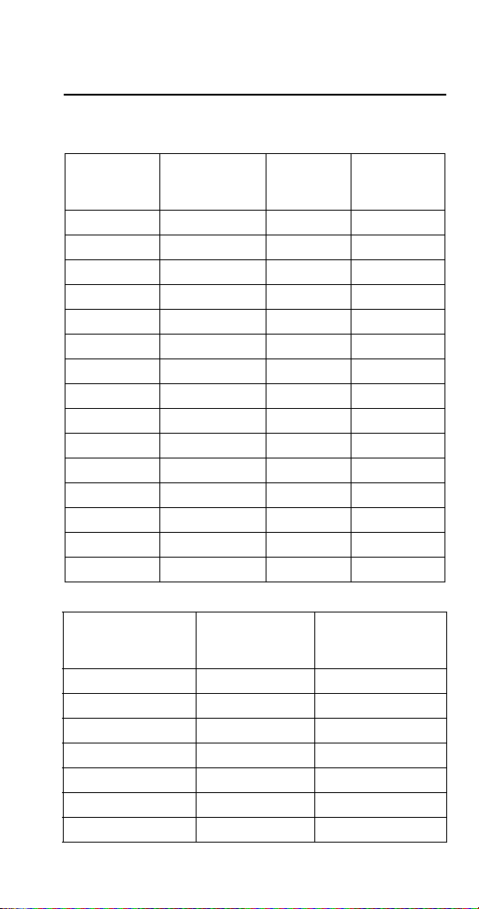
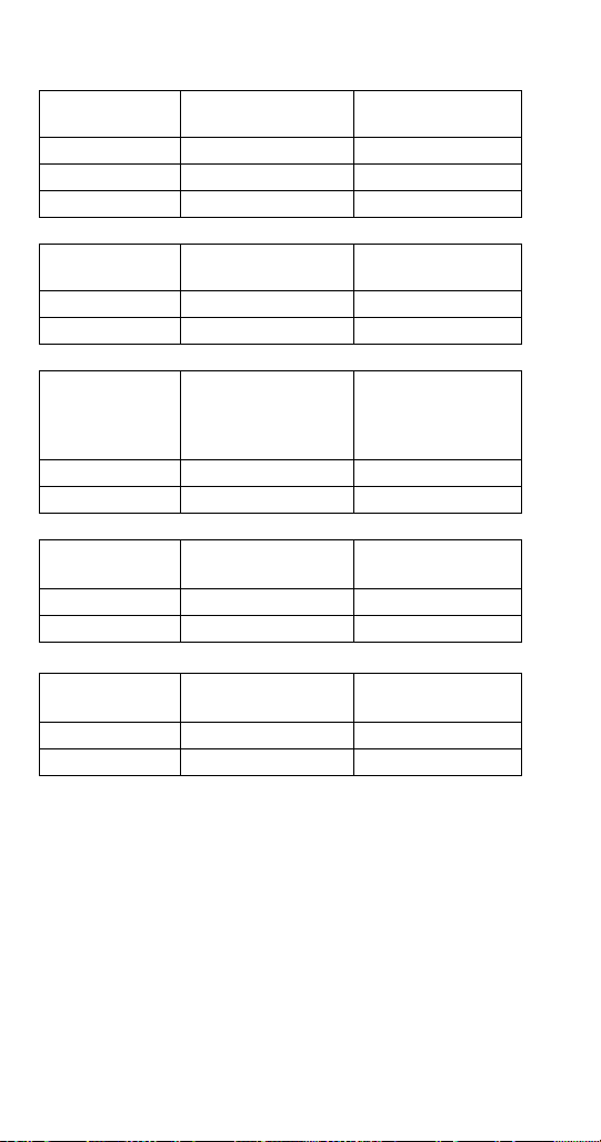
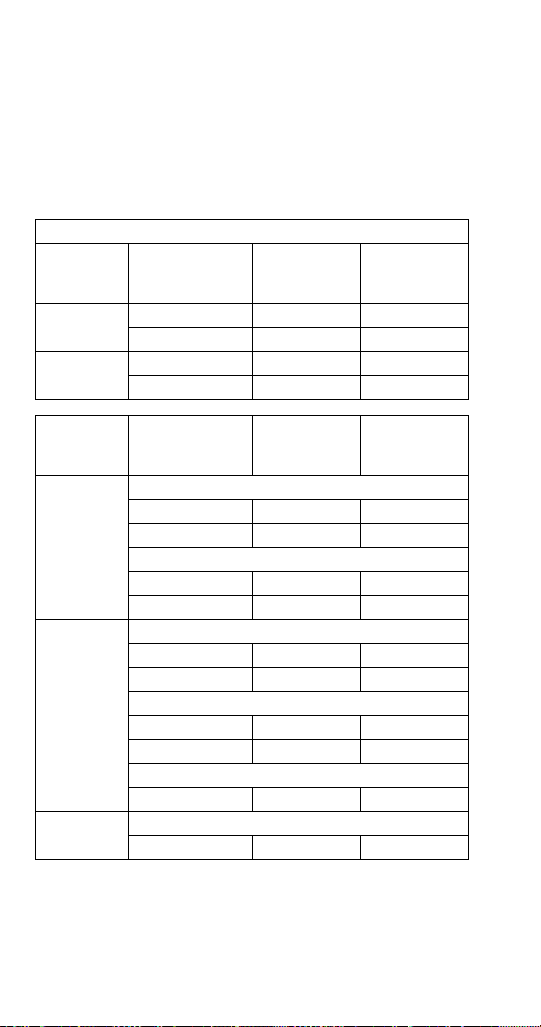
Model Numbers
Head Section Models
Self-
Contained
Air-Cooled
SN012A (T) NA NA NA
SN020A (T) NA N/A NA
QF0406A NA NA NA
SF0406A SN0407W NA NA
SN0458A SN0459W NA NA
SF0606A SF0607W SF0696N NA
SN0658A SN0659W SN0698N NA
QC0708A QC0709W NA NA
QF0806A QF0807W NA NA
SF0906A SF0907W NA SF0976C
SN0958A SN0959W NA SN0978C
SF1206A SF1207W NA SF1276C
SN1258A SN1259W NA SN1278C
NA NA NA QF2296N
NA NA NA QF2396N
Remote Condenser Models
Head Section
SN0650 JC0495 NA
SF0976C NA RFC0985
SN0978C NA RFC0985
SF1276C NA RFC1285
SN1278C NA RFC1285
QF2296N NA RFC2085
QF2396N NA RFC2385
Self-
Contained
Water-Cooled
Traditional
Remote
Condenser
Traditional
Remote
Condenser
Condensing Unit
Remote
Condensing
Remote
Unit
Part Number 80-1230-9 10/10 13
Page 14
NOTE: Model numbers ending in 3 indicate a 3-phase
!
Warning
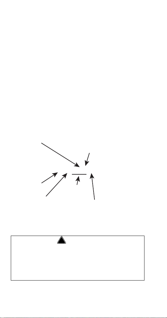
Q F 0807 W
ICE MACHINE
MODEL
ICE CUBE SIZE
F FLAKE
C CHIPLET
# CUBE SIZE
6 FLAKE
7 FLAKE
8 CHIPLET
9 CHIPLET
CONDENSER TYPE
AIR-COOLED
WATER-COOLED
AIR-COOLED
WATER-COOLED
A SELF-CONTAINED AIR-COOLED
W SELF-CONTAINED WAT ER-COOLED
N REMOTE AIR-COOLED
9 REMOTE
AIR-COOLED
CONDENSER TYPE
ICE MACHINE
SERIES
unit. Example: RFC12853
* Traditional Remotes - condenser is outside,
compressor is inside. The heat is rejected outside.
Line set consists of a hi gh pressure d ischarge li ne and
a high pressure liquid line. Only models ending in “N”
use Traditional Remote Condensers.
** RFC Remote Condensing Unit - compressor,
condenser, accumulator and head pressure control
valve outside. Line set consists of a low pressure
suction line and a high pressure liquid line. Only
models ending in “C” use RFC Remote Condensing
Units.
HOW TO READ A MODEL NUMBER
Personal Injury Potential
The ice machine must be attached to the adapter
and dispenser to prevent the ice machine from
falling. Mounting brackets are provided with all
Nugget ice machines.
14 Part Number 80-1230-9 10/10
Page 15
MODEL/SERIAL NUMBER LOCATION
!
Caution
Important
These numbers are required when requesting
information from your local Manitowoc Distributor,
service representative, or Manitowoc Ice, Inc. The
model and serial number are listed on the OWNER
WARRANTY REGISTRATION CARD. They are also
listed on the MODEL/SERIAL NUMBER DECAL
affixed to the ice machine.
MANITOWOC CLEANER AND SANITIZER
Manitowoc Ice Machine Cleaner and Sanitizer are
available in 16 oz. (473 ml) bottles. These are the only
cleaners and sanitizer approved for use with
Manitowoc products.
Flake/Chiplet/Nugget models must use cleaner part
number 000000084 ONLY
to the evaporator will result with repeated use or
high concentrations of standard (green) cleaner.
This damage is not covered by the warranty.
Cleaner Part Number Sanitizer Part Number
16 oz. 000000084 16 oz. 94-0565-3
1 gal N/A 1 gal. 94-0581-3
ICE MACHINE WARRANTY INFORMATION
Owner Warranty Registration Card
Warranty coverage begins the day the ice machine is
installed.
Complete and mail the OWNER WARRANTY
REGISTRATION CARD as soon as possible to
validate the installation date.
If the OWNER WARRANTY REGISTRA TION CARD is
not returned, Manitowoc will use the date of sale to the
Manitowoc Distributor as the first day of warranty
coverage for your new ice machine.
(clear cleaner). Damage
Part Number 80-1230-9 10/10 15
Page 16

Q Model & S Model Flake/Chiplet/Nugget Commercial Warranty
Manitowoc Ice, Inc. (hereinafter referred to as the
"COMPANY") warrants for a period of twenty four
months from the installation date (except as limited
below) that new Flake/Chiplet ice machines
manufactured by the COMPANY shall be free of
defects in material or workmanship under normal and
proper use and maintenance as specified by the
COMPANY and upon proper installation and start-up
in accordance with the instruction manual supplied
with the ice machine. The COMPANY'S warranty
hereunder with respect to the compressor shall apply
for an additional thirty-six months, excludi n g al l labo r
charges.
The obligation of the COMPANY under this warranty is
limited to the repair or replacement of parts,
components, or assemblies that in the opinion of the
COMPANY are defective. This warranty is further
limited to the cost of parts, components or assemblies
and standard straight time labor charges at the
servicing location.
Time and hourly rate schedules, as published from
time to time by the COMPANY, apply to all service
procedures. Additional expenses including without
limitation, travel time, overtime premium, material cost,
accessing or removal of the ice machine, or shipping
are the responsibility of the owner, along with all
maintenance, adjustments, cleaning, and ice
purchases. Labor covered under this warranty must be
performed by a COMPANY Contracted Service
Representative or a refrigeration service agency as
qualified and authorized by the COMPANY'S local
Distributor. The COMPANY'S liability under this
warranty shall in no event be greater than the actual
purchase price paid by customer for the ice machine.
16 Part Number 80-1230-9 10/10
Page 17

The foregoing warranty shall not apply to (1) any part
or assembly that has been altered, modified, or
changed; (2) any part or assembly that has been
subjected to misuse, abuse, neglect, or accidents; (3)
any ice machine that has been installed and/or
maintained inconsistent with the technical instructions
provided by the COMPANY; or (4) any ice machine
initially installed more than five years from the serial
number production date. This warranty shall not apply
if the Ice Machine's refrigeration system is modified
with a condenser, heat reclaim device, or parts and
assemblies other than those manufactured by the
COMPANY, unless the COMPANY approves these
modifications for specific locations in writing.
THIS WARRANTY IS IN LIEU OF ALL OTHER
WARRANTIES OR GUARANTEES OF ANY KIND,
EXPRESSED OR IMPLIED, INCLUDING ANY
IMPLIED WARRANTY OF MERCHANTABILITYOR
FITNESS FOR A PARTICULAR PURPOSE. In no
event shall the COMPANY be liable for any special,
indirect, incidental or consequential damages. Upon
the expiration of the warranty period, the COMPANY'S
liability under this warranty shall terminate. The
foregoing warranty shall constitute the sole liability of
the COMPANY and the exclusive remedy of the
customer or user.
To secure prompt and continuing warranty service, the
warranty registration card must be completed and sent
to the COMPANY within five (5) days from the
installation date.
Complete the following and retain for your record:
Distributor/Dealer
Model Number Serial Number
Installation Date
MANITOWOC ICE
2110 So. 26th St., P.O. Box 1720, Manitowoc, WI 54220
Telephone: 920-682-0161 Fax: 920-683-7585
Web Site - www.manitowocice.com
Part Number 80-1230-9 10/10 17
Page 18

Q Model & S Model Flake/Chiplet/Nugget Residential Warranty
WHAT DOES THIS LIMITED WARRANTY COVER?
Subject to the exclusions and limitations below,
Manitowoc Ice, Inc. (“Manitowoc”) warrants to the
original consumer that any new ice machine
manufactured by Manitowoc (the “Product”) shall be
free of defects in material or workmanship for the
warranty period outlined below under normal use and
maintenance, and upon proper installation and startup in accordance with the instruction manual supplied
with the Product.
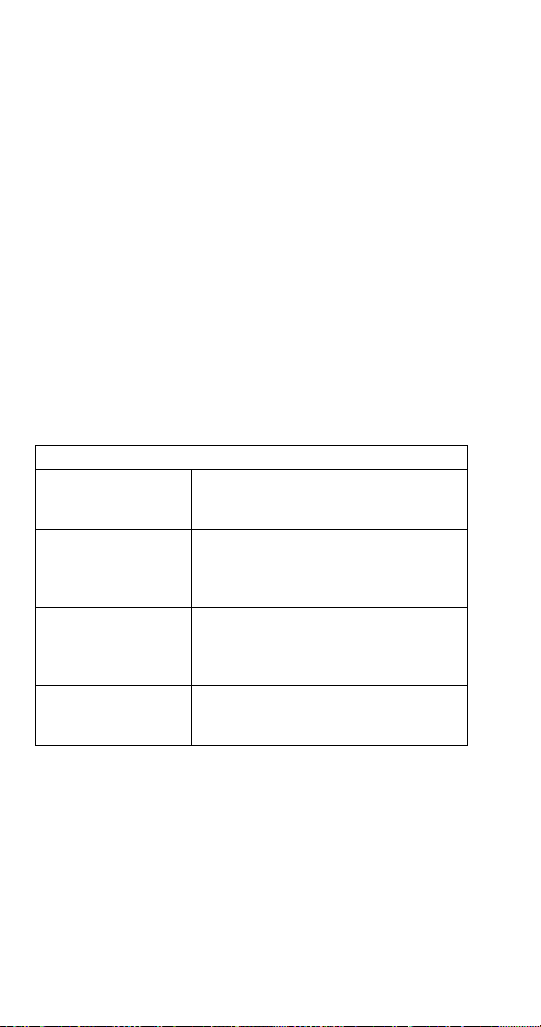
HOW LONG DOES THIS LIMITED WARRANTY
LAST?
Product Covered Warranty Period
Ice Machine
WHO IS COVERED BY THIS LIMITED WARRANTY?
This limited warranty only applies to the original
consumer of the Product and is not transferable.
Twelve months from the
sale date
18 Part Number 80-1230-9 10/10
Page 19

WHAT ARE MANITOWOC ICE’S OBLIGATIONS
UNDER THIS LIMITED WARRANTY?
If a defect arises and Manitowoc receives a valid
warranty claim prior to the expiration of the warranty
period, Manitowoc shall, at its option: (1) repair the
Product at Manitowoc’s cost, including standard
straight time labor charges, (2) replace the Product
with one that is new or at least as functionally
equivalent as the original, or (3) refund the purchase
price for the Product. Replacement parts are
warranted for 90 days or the balance of the original
warranty period, whichever is longer. The foregoing
constitutes Manitowoc’s sole obligation and the
consumer’s exclusive remedy for any breach of this
limited warranty. Manitowoc’ s liability under this limited
warranty is limited to the purchase price of Product.
Additional expenses including, without limitation,
service travel time, overtime or premium labor
charges, accessing or removing the Product, or
shipping are the responsibility of the consumer.
HOW TO OBTAIN WARRANTY SERVICE
To obtain warranty service or information regarding
your Product, please contact us at:
MANITOWOC ICE
2110 So. 26th St. P.O. Box 1720, Manitowoc, WI
54221-1720
Telephone: 920-682-0161 Fax: 920-683-7585
www.manitowocice.com
Part Number 80-1230-9 10/10 19
Page 20

WHAT IS NOT COVERED?
This limited warranty does not cover, and you are
solely responsible for the costs of: (1) periodic or
routine maintenance, (2) repair or replacement of the
Product or parts due to normal wear and tear, (3)
defects or damage to the Product or parts resulting
from misuse, abuse, neglect, or accidents, (4) defects
or damage to the Product or parts resulting from
improper or unauthorized alterations, modifications, or
changes; and (5) defects or damage to any Product
that has not been installed and/or maintained in
accordance with the instruction manual or technical
instructions provided by Manitowoc. To the extent that
warranty exclusions are not permitted under some
state laws, these exclusions may not apply to you.
E
XCEPT AS STATED IN THE FOLLOWING SENTENCE, THIS
IMITED WARRANTY IS THE SOLE AND EXCLUSIVE
L
W
ARRANTY OF MANITOWOC WITH REGARD TO THE
P
RODUCT. ALL IMPLIED WARRANTIES ARE STRICTLY
IMITED TO THE DURATION OF THE LIMITED WARRANTY
L
A
PPLICABLE TO THE PRODUCTS AS STATED ABOVE,
I
NCLUDING BUT NOT LIMITED TO, ANY WARRANTY OF
ERCHANTABILITY OR OF FITNESS FOR A PARTICULAR
M
P
URPOSE.
Some states do not allow limitations on how long an
implied warranty lasts, so the above limitation may not
apply to you.
20 Part Number 80-1230-9 10/10
Page 21

IN NO EVENT SHALL MANITOWOC OR ANY OF ITS
A
FFILIATES BE LIABLE TO THE CONSUMER OR ANY
THER PERSON FOR ANY INCIDENTAL, CONSEQUENTIAL
O
O
R SPECIAL DAMAGES OF ANY KIND (INCLUDING,
W
ITHOUT LIMITATION, LOSS OF PROFITS, REVENUE OR
USINESS) ARISING FROM OR IN ANY MANNER
B
C
ONNECTED WITH THE PRODUCT, ANY BREACH OF THIS
L
IMITED WARRANTY, OR ANY OTHER CAUSE
HATSOEVER, WHETHER BASED ON CONTRACT, TORT
W
O
R ANY OTHER THEORY OF LIABILITY.
Some states do not allow the exclusion or limitation of
incidental or consequential damages, so the above
limitation or exclusion may not apply to you.
HOW STATE LAW APPLIES
This limited warranty gives you specific legal rights,
and you may also have rights that vary from state to
state or from one jurisdiction to another.
REGISTRATION CARD
T o secure prompt and continuing warranty service, this
warranty registration card must be completed and sent
to Manitowoc within thirty (30) days from the sale date.
Complete the registration card and send it to
Manitowoc.
Part Number 80-1230-9 10/10 21
Page 22

22 Part Number 80-1230-9 10/10
This Page Intentionally Left Blan k
Page 23
Installation
!
Warning
PERSONAL INJURY POTENTIAL
Remove all ice machine panels before lifting and
installing.
Location of Ice Machine
The location selected for the ice machine must meet
the following criteria. If any of these criteria are not
met, select another location.
• The location must be indoors.
• The location must be free of airborne and other
contaminants.
• The air temperature must be at least 45°F (7°C),
but must not exceed 110°F (43°C).
• The water temperature must be at least 45°F
(7°C), but must not exceed 90°F (32°C).
• The location must not be near heat-generating
equipment or in direct sunlight.
• The location must be capable of supporting the
weight of the ice machine and a full bin of ice.
• The location must allow enough clearance for
water, drain and electrical connections in the rear
of the ice machine.
• The location must not obstruct airflow through or
around the ice machine. Refer to the chart below
for clearance requirements.
• RFC Condensing Units ONLY - Interconnecting
wiring (115/60/1 or 230/50/1) is required between
the ice machine and condensing unit to energize
the contactor coil.
• The ice machine must be protected if it will be
subjected to temperatures below 32°F (0°C).
Failure caused by exposure to freezing
temperatures is not covered by the warranty. See
“Removal from Service/Winterization”
Part Number 80-1230-9 10/10 23
Page 24
Ice Machine Clearance Requirements
SN12/SN20
Top 24" (61.0 cm) NA
Sides 8" (20.3 cm) NA
Back 5" (12.7 cm) NA
Self-Contained
Air-Cooled
Water-Cooled*
QF400
Self-Contained
Air-Cooled
Water-Cooled
and Remote*
Top/Sides 5" (12.7 cm) NA
Back 5" (12.7 cm) NA
SF400/SN450
SF600/SN650
SF900/SN950
Self-Contained
Air-Cooled
Water-Cooled
and Remote*
S1200/SN1250
Top/Sides 8" (20.3 cm) 8" (20.3 cm)*
Back 5" (12.7 cm) 5" (12.7 cm)*
QF800
QC700
Self-Contained
Air-Cooled
Water-Cooled
and Remote*
Top/Sides 8" (20.3 cm) 5" (12.7 cm)*
Back 5" (12.7 cm) 5" (12.7 cm)*
QF2200
QF2300
Self-Contained
Air-Cooled
Water-Cooled
and Remote*
Top/Sides NA 5" (12.7 cm)*
Back NA 5" (12.7 cm)*
* Water-Cooled and Remotes Only - There is no minimum clearance
required. This value is recommended for efficient operation and
servicing only.
NOTE: SN12/SN20 airflow is in the left side and out the top.
QF400 is in and out the front of the ice machine.
24 Part Number 80-1230-9 10/10
Page 25

Ice Machine Heat of Rejection
Series
Ice Machine
SN12/SN20 2,300
QF400 4,000
SF400/SN450 3,400
SF600/SN650 5,300
QF800/QC700 7,800
SF900/SN950
SF900C/SN950C
SF1200/SN1250
SF1200C/SN1250C
QF2200/QF2300 21,000
BTU/Hour
*
Because the heat of rejection varies during the ice making cycle,
the figure shown is an average.
Heat of Rejection*
Air Conditioning
9,000
16,000
Ice machines, like other refrigeration equipment, reject
heat through the condenser. It is helpful to know the
amount of heat rejected by the ice machine when
sizing air conditioning equipment where self-contained
air-cooled ice machines are installed.
This information is also necessary when evaluating
the benefits of using water-cooled or remote
condensers to reduce air conditioning loads. The
amount of heat added to an air conditioned
environment by an ice machine using a water-cooled
or remote condenser is negligible.
Knowing the amount of heat rejected is also important
when sizing a cooling tower for a water-cooled
condenser. Use the peak figure for sizing the cooling
tower.
Part Number 80-1230-9 10/10 25
Page 26
Location of Tr aditional Remote Uni t s and Remote condensing units
The location selected for the Remote Units must meet
the following criteria. If any of these criteria are not
met, select another location.
• The air temperature must be at least -20°F
(-28.9°C) but must not exceed 120°F (49°C).
• The location must not allow exhaust fan heat and/
or grease to enter the condenser.
• The location must not obstruct airflow through or
around the condensing unit. Refer to the chart
below for clearance requirements.
• RFC Condensing Units ONLY - Interconnecting
wiring (115/60/1) is required between the ice
machine and condensing unit to energize the
contactor coil.
Traditional Remote/Condensing Unit Clearances
Traditional Remote
JC0495
Top/Bottom
Traditional Remote
JC0495
Sides
Remote
Condensing Unit
RFC - Top/Sides
Remote
Condensing Unit
RFC - Front/Back
Bottom clearance is 12" (31 cm)
Top clearance is 4’ (1.2 m)
There is no minimum clearance
required, although 6" (15 cm) is
recommended for efficient operation
and servicing only.
There is no minimum clearance
required, although 6" (15 cm) is
recommended for efficient operation
and servicing only.
4’ (1.2 m)
26 Part Number 80-1230-9 10/10
Page 27
Electrical Service
!
Warning
!
Warning
General
All wiring must conform to local, state and national
codes.
Voltage
The maximum allowable voltage variation is ± 10% of
the rated voltage on the ice machine model/serial
number plate at start-up (when the electrical load is
highest).
Fuse/Circuit Breaker
A separate fuse/circuit breaker must be provided for
each ice machine. Circuit breakers must be H.A.C.R.
rated (does not apply in Canada).
The ice machine must be grounded in accordance
with national and local electrical codes.
SN012/SN020/QF0400 115/60/1 ice machines are
factory pre-wired with a power cord and 5-15P plug
confirmation.
SN012/SN020/QF0400 230/50/1 ice machines are
factory pre-wired with a power cord, no plug is
supplied.
SF0400/SN0450/SF0600/SN0650/SF0900/SN0950/
SF1200/SN1250 ice machines are not supplied with a
power cord.
SF0900C/SN0950C/SF1200C/SN1250C/
QF2200/QF2300 with Remote Condensing Unit the
ice machine head section and remote condensing unit
are wired independent of each other. A separate
dedicated fuse/circuit breaker must be provided
each condensing unit. Circuit breakers must be
H.A.C.R. rated (does not apply in Canada).
for
Part Number 80-1230-9 10/10 27
Page 28
CIRCUIT AMPACITY
The minimum circuit ampacity is used to help select
the wire size of the electrical supply. (Minimum circuit
ampacity is not the ice machine’s running amp load.)
The wire size (or gauge) is also dependent upon
location, materials used, length of run, etc., so it must
be determined by a qualified electrician.
Self Contained Air-Cooled
Ice
Machine
SN012
SN020
QF0400
Voltage
Phase Cycle
115/1/60 15 10.3
230/1/50 15 4.6
115/1/60 15 9.8
230/1/50 15 4.2
Max. Fuse/
Circuit
Breaker
Total
Amps
Ice
Machine
SF0400/
SN0450
SF0600/
SN0650
JC0495
28 Part Number 80-1230-9 10/10
Voltage
Phase
Cycle
115/1/60 20 13.7
230/1/50 15 7.2
115/1/60 20 12.9
230/1/50 15 6.6
115/1/60 20 16.2
230/1/50 15 7.0
115/1/60 20 15.5
230/1/50 15 6.7
115/1/60 20 17.9
Traditional Remote Condenser
115/60/1 NA 2.3
Max. Fuse/
Circuit
Breaker
Air-Cooled
Water-Cooled
Air-Cooled
Water-Cooled
Remote Air-Cooled
Minimum
Circuit
Amps
Page 29
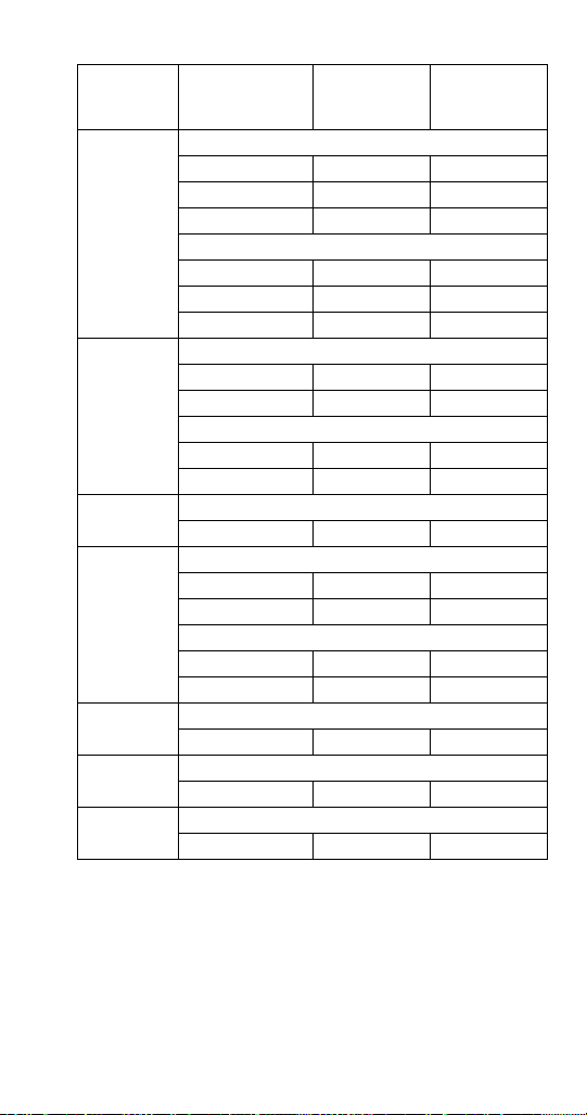
Ice
Machine
QC0700/
QF0800
SF0900/
SN0950
SF0900C/
SN0950C
SF1200/
SN1250
SF1200C/
SN1250C
QF2200
QF2300
Voltage
Phase
Cycle
115/1/60 30 18.9
230/1/50 20 8.8
230/1/60 15 8.7
115/1/60 30 17.9
230/1/50 20 8.4
230/1/60 15 8.3
230/1/50 15 7.0
230/1/60 15 8.0
230/1/50 15 6.7
230/1/60 15 7.7
Air-Cooled Head Section
115/1/60 15 1.7
230/1/50 15 8.0
230/1/60 15 9.8
230/1/50 15 7.7
230/1/60 15 9.0
Air-Cooled Head Section
115/1/60 15 2.1
Remote Air-Cooled Head Section
115/1/60 15 4.3
Remote Air-Cooled Head Section
115/1/60 15 5.5
Max. Fuse/
Circuit
Breaker
Air-Cooled
Water-Cooled
Air-Cooled
Water-Cooled
Air-Cooled
Water-Cooled
Minimum
Circuit
Amps
Part Number 80-1230-9 10/10 29
Page 30

Condensing
Unit
RFC0985
used with
SF0900C/
SN0950C
RFC1285
used with
SF1200C/
SN1250C
RFC2085
used with
QF2200
RFC2385
used with
QF2300
Voltage
Phase
Cycle
Max.
Fuse/
Circuit
Breaker
Minimum
Circuit
Amps
Remote Condensing Unit
208-230/1/60 15 8.6
208-230/1/50 15 8.0
Remote Condensing Unit
208-230/1/60 15 9.2
208-230/3/60 15 6.8
208-230/1/50 15 12.0
Remote Condensing Unit
208-230/1/60 30 15.6
208-230/3/60 20 11.2
Remote Condensing Unit
208-230/1/60 30 18.5
208-230/3/60 20 12.8
30 Part Number 80-1230-9 10/10
Page 31

Ice Machine Head Section Water
Important
Supply and Drains
POTABLE WATER SUPPLY
Local water conditions may require treatment of the
water to inhibit scale formation, filter sediment, remove
chlorine, and improve taste and clarity.
If you are installing a Manitowoc water filter system,
refer to the Installation Instructions supplied with the
filter system for ice making water inlet connections.
POTABLE WATER INLET LINES
Follow these guidelines to install water inlet lines:
• Do not connect the ice machine to a hot water
supply. Be sure all hot water restrictors inst alled for
other equipment are working. (Check valves on
sink faucets, dishwashers, etc.)
• If water pressure exceeds the maximum
recommended pressure of 80 psig (5.5 Bar),
obtain a water pressure regulator from your
Manitowoc Distributor.
• Install a water shut-of f valve and union for both the
ice making and condenser water lines.
• Insulate water inlet lines to prevent condensation.
Part Number 80-1230-9 10/10 31
Page 32

DRAIN CONNECTIONS
Follow these guidelines when installing drain lines to
prevent drain water from flowing back into the ice
machine and storage bin:
• Drain lines must have a 1.5 in. (3.8 cm) drop per 5
ft. of run (2.5 cm per meter), and must not create
traps.
• The floor drain must be large enough to
accommodate drainage from all drains.
• Run separate bin and water-cooled condenser
drain lines. Insulate them to prevent condensation.
• Vent the bin drain to the atmosphere. Do not vent
the condenser drain on water-cooled models.
• Drains must have a union or other suitable means
to allow a place of disconnection from the ice
machine when servicing is required.
COOLING TOWER APPLICATIONS (WATER-COOLED MODELS)
A water cooling tower installation does not require
modification of the ice machine. The water regulator
valve for the condenser continues to control the
refrigeration discharge pressure.
It is necessary to know the amount of heat rejection,
(refer to page 25) and the pressure drop through the
condenser and water valves (inlet and outlet) when
using a cooling tower on an ice machine.
• Water entering the condenser must not exceed
90°F (32°C).
• Water flow through the condenser must not
exceed 5 gal. (19 L) per minute.
• Allow for a pressure drop of 7 psi (48 kPa)
between the condenser water inlet and the outlet
of the ice machine.
• Water exiting the condenser must not exceed
110°F (43°C).
32 Part Number 80-1230-9 10/10
Page 33

INSTALLING ON A DISPENSER
!
Warning
!
Caution
Nugget ice is soft and chewable. This characteristic
makes this ice more difficult to dispense. All dispenser
manufacturers require a kit be installed for Nugget
type ice. Contact the dispenser manufacturer for the
correct adapter and nugget dispensing kit for your
specific model dispenser. The required kit can vary by
dispenser size from the same manufacturer.
Failure to install the correct kit and make the
necessary modifications on the dispenser will result in:
• Congealed ice which will not dispense and will
damage the ice machine and dispenser
• Insufficient ice contact with the cold plate which
will result in an inferior product
• A safety issue if ice lifts the adapter or ice machine
Nugget Dispensing Kit Installation Procedure
1. Follow the dispenser manufacturers instructions
for installation of the adapter (if required) and
nugget ice kit.
2. Make all necessary beverage, electrical and drain
connections to the dispenser.
3. Level the dispenser front to back and side to side.
4. Install ice machine on dispenser and secure ice
machine, dispenser and adapter with provided
brackets.
5. Complete water, drain and electrical connections
to the ice machine.
The ice machine and adapter must be attached to the
dispenser to prevent the ice machine from falling.
Ice machines in low volume locations may experience
congealing. Thermostat kit K00364 must be added in these
locations to prevent damage to the ice machine and dispenser.
Part Number 80-1230-9 10/10 33
PERSONAL INJURY POTENTIAL
Page 34

LINE SET REQUIREMENTS
Traditional Remote Units Only
Ice Machine
Head Section
SN0650 JC0495
Line Set
RM20/35/50
Discharge
Condenser Line Set
Line
5/16 in
(7.9 mm)
Liquid
Line
1/4 in
(7 mm)
RM-20
RM-35
RM-50
Insulation
Thickness
12.7 mm
QuietQube Remote Condensing Units Only
Ice Machine
Head Section
SF0900C
SN0950C
SF1200C
SN1250C
QF2200/QF2300
Line Set
RC-21
RC-31
RC-51
RC-20
RC-30
RC-50
(15.9 mm)
(19.1 mm)
Suction
Line
5/8 in
3/4 in.
Condensing
Unit
RFC0985
RFC1285
RFC2085
RFC2385
Liquid
Line
3/8 in
(9.5 mm)
1/2 in.
(12.7 mm)
Line Set
RC-21
RC-31
RC-51
RC-21
RC-31
RC-51
RC-20
RC-30
RC-50
Insulation
Thickness
1/2 in
(12.7 mm)
Suction Line
1/2" (13 mm)
Liquid Line
1/4" (7 mm)
1/2 in
34 Part Number 80-1230-9 10/10
Page 35

• Maximum total amount of tubing is 100’ (30.5 M)
Important
• Maximum height condenser or condensing unit
can be above ice machine is 35’ (10.7 M)
• Maximum distance condenser or condensing unit
can be below the ice machine 15’ (4.5 M)
• Condensing units only - Suction line oil trap is
required for any rise that is 20’ (6 M) or greater.
• Refer to Installation Use and Care Manual for
complete installation information.
Manitowoc remote systems are only approved
and warranted as a complete new package.
Warranty on the refrigeration system will be
void if a new ice machine head section is
connected to pre-existing (used) tubing or
remote condensers.
Part Number 80-1230-9 10/10 35
Page 36

36 Part Number 80-1230-9 10/10
This Page Intentionally Left Blan k
Page 37

Component Identification
WATER LEVEL PROBES
WATER FLOAT VALVE
COIL
EVAPORATOR
GEAR MOTOR /
GEAR BOX
ASSEMBLY
ICE/OFF/CLEAN
TOGGLE SWITCH
CONDESER
FAN/ MOTOR
POTABLE
WATER
DRAIN
CONTROL BOX
QF400 Air-cooled
Part Number 80-1230-9 10/10 37
Page 38

QF800/QC700 Air & Water-cooled
CONDENSER
FAN MOTOR
ICE/OFF/CLEAN
TOGGLE SWITCH
ICE CHUTE
CLEANING
SOLUTION FILL
HOLE
WATER LEVEL
PROBE
DUMP
VALVE
38 Part Number 80-1230-9 10/10
Page 39

SF0400/SN0450/SF0600/SN0650/SF0900/
R
CONDENSER FAN
MOTOR
ICE CHUTE
GEAR BOX
AIR-COOLED
CONDENSER
EVAPORATOR
WATER
RESERVOIR
DRAIN FITTING
WATER INLET
DUMP VALVE
SN0950/SF1200/SN1250 Air & Watercooled
AIR BAFFLE
ELECTRICAL
ENTRANCE
GEAR
MOTOR
COMPRESSO
Part Number 80-1230-9 10/10 39
Page 40

GEAR
MOTOR
ICE CHUTE
COVER
HALL EFFECT
SWITCH
WATER
RESERVOIR
CONTROL BOX
CONTROL
BOARD
TOGGLE
SWITCH
40 Part Number 80-1230-9 10/10
Page 41

SF0600/SN0650/SF0900/SN0950/SF1200/
EVAPORATOR
WATER
RESERVOIR
WATER
DUMP VALVE
GEAR
MOTOR
RECEIVER
DRIER
WATER
INLET
CONTROL
BOX
HALL EFFECT
SWITCH
COOL VAPOR
VALV E
EXPANSION
VALV E
QuietQube Only
SUCTION
LINE
&
LIQUID
LINE
SN1250 Remote & QuietQube Model
Part Number 80-1230-9 10/10 41
Page 42

42 Part Number 80-1230-9 10/10
This Page Intentionally Left Blan k
Page 43

Maintenance
!
Caution
!
Caution
!
Warning
!
Warning
Maintenance procedures or failures due to a lack of
maintenance are not covered by the warranty.
Manitowoc Ice Machine Cleaner and Sanitizer are the
only products approved for use in Manitowoc ice
machines.
Use the correct Manitowoc approved metal safe Ice
Machine Cleaner (part number 000000084) and
Sanitizer (part number 94-0565-3). It is a violation of
Federal law to use these solutions in a manner
inconsistent with their labeling. Read and
understand all labels printed on bottles before use.
Do not mix Cleaner and Sanitizer solutions toge ther.
It is a violation of Federal law to use these solutions
in a manner inconsistent with their labeling.
Wear rubber gloves and safety goggles (and/or face
shield) when handling ice machine Cleaner or
Sanitizer.
If you do not understand the procedures or the
safety precautions that must be followed, call your
local Manitowoc Distributor or Manitowoc Ice.
Part Number 80-1230-9 10/10 43
Page 44

Manitowoc’s Cleaning Technology
Manitowoc Flake/Nugget Ice Machines allow the
initiation and completion of a cleaning cycle at the flip
of a switch. This cycle will permit cleaning of all
surfaces that come in contact with the water
distribution system. Periodic maintenance must be
performed that includes sanitizing the bin and adjacent
surface areas, which are not contacted by the water
distribution system.
Depending on local water conditions Manitowoc
recommends initiating preventative maintenance
cleaning procedures between the 6 month cleanings.
This preventive maintenance removes mineral buildup from the evaporator, which results in peak
efficiency and lower operating costs.
This technology allows initiation and completion of a
clean cycle, after which the ice machine automatically
starts ice making again.
There are three separate cleaning procedures.
Heavily Scaled Cleaning Procedure
Perform this procedure if you have some or all of these
symptoms.
• Grinding, popping or squealing noises from the
evaporator.
• Grinding noise from gearbox.
• Ice machine trips speed sensor.
A Cleaning/Sanitizing Procedure must be performed
after this procedure.
Cleaning/Sanitizing Procedure
This procedure must be performed a minimum of once
every six months:
• All ice must be removed from the bin/dispenser.
• The ice machine and bin/dispenser must be
disassembled, cleaned and sanitized.
• The ice machine produces ice with the cleaner and
sanitizer solutions.
• All ice produced during the cleaning and sanitizing
procedure must be discarded
44 Part Number 80-1230-9 10/10
Page 45

Preventative Maintenance Cleaning Procedure
Perform this procedure as often as required for your
water conditions:
• Allows cleaning the ice machine without removing
all of the ice from the bin/dispenser.
• Removes mineral deposits from areas that are in
direct contact with water during the Freeze cycle
(reservoir, evaporator, auger, drain lines).
.
EXTERIOR CLEANING
Clean the area around the ice machine as often as
necessary to maintain cleanliness and efficient
operation. Use cleaners designed for use with
stainless steel products.
Sponge any dust and dirt off the outside of the ice
machine with mild soap and water. Wipe dry with a
clean, soft cloth.
Heavy stains should be removed with stainless steel
wool. Never use plain steel wool or abrasive pads.
They will scratch the panels.
SN012/SN020 Only
WEEKLY
Remove grill from scrap ice tray and wipe splash
panel, scrap ice tray and grill with sanitizer & water
solution. Pour excess solution in scrap ice tray to clear
drain.
TOUCHLESS SENSOR ONLY
Wipe sensor window with a soft cloth and mild
detergent. Rinse with clear water and dry with a clean
soft cloth.
Dust and dirt can be removed from exterior surfaces
with mild household dish-washing detergent and warm
water. Wipe dry with a clean, soft cloth.
Part Number 80-1230-9 10/10 45
Page 46

Preventative Maintenance Procedure
!
Caution
QF0400
Preventative Maintenance Cleaning Procedure
Step 1 Set the toggle switch to the OFF position.
Open bin door and remove the 2 thumbscrews and
back evaporator panel.
Step 2 To start a cleaning cycle, move the toggle
switch to the CLEAN position. Water will flow through
the water dump valve and down the drain. The flush,
gear motor, speed, dump valve and water solenoid
lights will energize to indicate the ice machine is in the
cleaning mode.
Step 3 Wait about 1 minute or until the dump valve
light de-energizes. Lift the front cover on the reservoir
and add the proper amount of Manitowoc Ice Machine
Cleaner
.
Use Manitowoc clear (P/N 000000084) Ice
Machine Cleaner only. It is a violation of Federal
law to use these solutions in a manner
inconsistent with their labeling. Read and
understand all labels printed on bottles before
use.
Model
QF0400 2 oz. (60 ml)
Step 4 The ice machine will automatically time out
four Flush and Rinse cycles, and then stop. The Flush
light remains energized until the toggle switch is
moved to the OFF position. This entire cycle lasts
approximately 11 minutes.
46 Part Number 80-1230-9 10/10
Amount of Cleaner Part
Number 000000084
Page 47

NOTE: Periodic cleaning must be performed on
adjacent surface areas not contacted by the water
distribution system.
Manitowoc recommends disassembling, cleaning and
sanitizing the ice machine and bin/dispenser a
minimum of once every six months.
Step 5
A. The ice machine may be set to start and
finish a cleaning procedure, and then
automatically start ice making again.
B. Wait about one minute into the cleaning cycle
(until the Dump Valve light de-energizes),
then move the switch from CLEAN to ICE
position.
When the cleaning cycle is complete, the Flush light
will turn off and ice making will start automatically.
Part Number 80-1230-9 10/10 47
Page 48

QC0700/QF0800/QF2200/QF2300
!
Caution
Preventative Maintenance Cleaning Procedure
Step 1 Remove front and top covers and set the
toggle switch to the OFF position.
Step 2 To start a cleaning cycle, move the toggle
switch to the CLEAN position. Water will flow through
the water dump valve and down the drain. The flush,
gear motor, speed, dump valve and water solenoid
lights will energize to indicate the ice machine is in the
cleaning mode.
Step 3 Remove the 1-1/2 in. plug from the top cover
of the water reservoir. Wait about one minute or until
the Dump Valve light de-energizes, then add the
proper amount of Manitowoc Ice Machine Cleaner and
reinstall the plug.
Use Manitowoc clear (P/N 000000084) Ice
Machine Cleaner only. It is a violation of Federal
law to use these solutions in a manner
inconsistent with their labeling. Read and
understand all labels printed on bottles before
use.
Model
QF0800/QC0700 3 oz. (90 ml)
QF2200/QF2300 3 oz. (90 ml)
Amount of Cleaner
(Part # 000000084)
Step 4 The ice machine will automatically time out
four Flush and Rinse cycles, and then stop. The Flush
light remains energized until the toggle switch is
moved to the OFF position. This entire cycle lasts
approximately 11 minutes.
48 Part Number 80-1230-9 10/10
Page 49

NOTE: Periodic cleaning must be performed on
adjacent surface areas not contacted by the water
distribution system.
Manitowoc recommends disassembling, cleaning and
sanitizing the ice machine and bin/dispenser a
minimum of once every six months.
Step 5
A. The ice machine may be set to start and
finish a cleaning procedure, and then
automatically start ice making again.
B. Wait about one minute into the cleaning cycle
(until the Dump Valve light de-energizes),
then move the switch from CLEAN to ICE
position.
C. When the cleaning cycle is complete, the
Flush light will turn off and ice making will
start automatically.
Part Number 80-1230-9 10/10 49
Page 50

SN012/SN020/SF0400/SN0450/SF0600/SN0650/
!
Caution
SF0900/SN0950/SF1200/SN1250
Preventative Maintenance
Ice machine cleaner is used to remove lime scale or
other mineral deposits. It is not used to remove algae
or slime. Refer to “Sanitizing Procedure” for removal of
algae and slime. To initiate a cleaning cycle using
Manitowoc’s Cleaning Technology use the following
procedure.
Step 1 To start a cleaning cycle, move the toggle
switch to the CLEAN position. Water will flow through
the water dump valve and down the drain.
Step 2 Remove the cover from the top of the ice
chute. Wait about one minute then add the proper
amount of Manitowoc Ice Machine Cleaner and reinstall cover.
Use only Manitowoc approved Ice Machine
Cleaner part number 000000084. It is a violation
of Federal law to use these solutions in a manner
inconsistent with their labeling. Read and
understand all labels printed on bottles before
use.
Model
SN12 SN20 2 ounces (60 ml)
SF0400 SN0450 2 ounces (60 ml)
SF0600 SN0650 3 ounces (90 ml)
SF0900 SN0950 6 ounces (180 ml)
SF1200 SN1250 8 ounces (240 ml)
SF2000 SN2050 12 ounces (360 ml)
50 Part Number 80-1230-9 10/10
Amount of Cleaner
Part Number 000000084
Page 51

Step 3 The ice machine will automatically time out a
ADD SOLUTION HERE
series of flush and rinse cycles, and then stops. This
entire cycle lasts approximately 30 minutes.
NOTE: Periodic cleaning must be performed on
adjacent surface areas not contacted by the water
distribution system.
NOTE: The ice machine may be set to start and finish
a cleaning procedure, and then automatically start ice
making again.
A. After cleaner is added move the switch from
CLEAN to ICE position.
B. When the cleaning cycle is complete ice
making will start automatically.
Part Number 80-1230-9 10/10 51
Page 52

Changing toggle switch position during clean
cycle:
1. Less than 60 seconds into Clean cycle - The
Clean cycle will end when the toggle switch is
moved to the OFF position.
2. More than 60 seconds into Clean cycle - The ice
machine will complete the clean cycle. Toggle
switch position will determine the next cycle after
the Clean cycle is completed.
• CLEAN POSITION - The ice machine will wait for
a change in toggle switch position.
• OFF POSITION - The ice machine will wait for a
change in toggle switch position.
• ICE POSITION - The ice machine will start making
ice automatically.
3. To abort the clean cycle move the toggle switch
from CLEAN to OFF to CLEAN and back to OFF
within a 15 second time period.
Manitowoc recommends disassembling, cleaning and
sanitizing the ice machine and dispenser every six
months.
52 Part Number 80-1230-9 10/10
Page 53

Heavily Scaled Procedure
QF0400
Procedure to Clean Heavily Scaled Ice Machines
Step 1 Remove all ice from the bin.
Step 2 Remove front and top covers and set the
toggle switch to the OFF position.
Step 3 Disconnect water supply line at float valve
quick disconnect by depressing stainless steel lever.
Step 4 Refer to chart below:
Pre-mix cleaner with lukewarm water in a non-
metallic container.
Amount of Cleaner
Part Number 000000084
Cleaner Water
32 oz
(0.94 L)
16 oz (0.5
L)
Model
QF0400
Water
Reservoir
Capacity
48 oz
(1.4 L)
Step 5 Remove all water from the evaporator and
water reservoir. Start an ice making cycle by moving
the toggle switch to the ICE position. Water will flow
through the water dump valve and down the drain for
45 seconds. After 45 seconds move the toggle switch
to the OFF position. Remove the plug from the top
cover of the water reservoir. Add the entire cleaner/
water solution and re-install the plug. Leave the
cleaner/water solution in the evaporator for a
minimum of 4 hours.
Step 6 Move the toggle switch from OFF to ICE. The
cleaner/water solution will flow through the water
dump valve and down the drain for 45 seconds.
Step 7 Move the toggle switch to the OFF position,
then follow the standard cleaning and
sanitizing procedures for the model ice machine you
are cleaning.
Part Number 80-1230-9 10/10 53
Page 54

QC0700/QF0800/QF2200/QF2300
Procedure to Clean Heavily Scaled Ice Machines
Step 1 Remove all ice from the bin.
Step 2 Remove front and top covers and set the
toggle switch to the OFF position.
Step 3 Disconnect water supply line at float valve
quick disconnect by depressing stainless steel lever.
Step 4 Refer to chart below:
Premix cleaner with lukewarm water in a
non-metallic container.
Amount of Cleaner
Part Number 000000084
Cleaner Water
Model
QF0800/
QC0700
QF2200/
QF2300
Water
Reservoir
Capacity
48 oz (1.4 L) 32 oz (0.94 L) 16 oz (0.5 L)
72 oz (2.1 L) 48 oz (1.4 L) 24 oz (0.7 L)
Step 5 Remove all water from the evaporator and
water reservoir. Start an ice making cycle by moving
the toggle switch to the ICE position. Water will flow
through the water dump valve and down the drain for
45 seconds. After 45 seconds move the toggle switch
to the OFF position. Remove the plug from the top
cover of the water reservoir. Add the entire cleaner/
water solution and re-install the plug. Leave the
cleaner/water solution in the evaporator for a
minimum of 4 hours.
Step 6 Move the toggle switch from OFF to ICE. The
cleaner/water solution will flow through the water
dump valve and down the drain for 45 seconds.
Move the toggle switch to the OFF position, then
follow the standard cleaning and
sanitizing procedures for the model ice machine you
are cleaning.
54 Part Number 80-1230-9 10/10
Page 55

SN012/SN020/SF0400/SN0450/SF0600/SN0650/ SF0900/SN0950/SF1200/SN1250
Procedure to Clean Heavily Scaled Flake/Nugget Ice Machines
Ice machines that are heavily scaled or have not been
cleaned on a regular basis will need to run this
Procedure. Failure to do so may result in binding of the
auger as the lime scale releases from the auger and
evaporator barrel.
Step 1 Remove panels and set the ICE/OFF/CLEAN
toggle switch to the OFF position.
Step 2 Remove all ice from the bin.
Step 3 Turn off the water supply to the ice machine.
Step 4 Place ICE/OFF/CLEAN toggle switch in the
CLEAN position. The dump valve will open and drain
the water from the evaporator and reservoir.
Step 5 Wait approximately 30 seconds (or until the
evaporator is drained) and place the toggle switch in
the OFF position.
Step 6 Refer to chart and add the correct amount of
cleaner for your model ice machine.
Model
SN12 SN20
SF0400 SN0450
SF0600 SN0650
SF0900 SN0950
SF1200 SN1250
SF2000 SN2050
Amount of Cleaner
Part Number 000000084
16 ounces (473 ml)
32 ounces (950 ml)
Part Number 80-1230-9 10/10 55
Page 56

Step 1 Turn on the water supply to the ice machine.
Important
ADD SOLUTION HERE
Leave the cleaner/water solution in the
evaporator for a minimum of 4 hours.
Step 2 Move the toggle switch to the ICE position.
The compressor will energize and produce ice with the
cleaning solution. Continue the freeze cycle for 15
minutes.
Step 3 Move the toggle switch to the OFF position,
then follow the standard cleaning and sanitizing
procedures.
56 Part Number 80-1230-9 10/10
Page 57

Cleaning And Sanitizing Procedure
QF0400
Cleaning and Sanitizing Procedure
Step 1 Set the toggle switch to the OFF position.
Open bin door and remove the 2 thumbscrews and
back evaporator panel.
Step 2 To start a cleaning cycle, move the toggle
switch to the CLEAN position. Water will flow through
the water dump valve and down the drain. The flush,
gear motor, speed, dump valve and water solenoid
lights will energize to indicate the ice machine is in the
cleaning mode.
Step 3 Wait about 1 minute or until the dump valve
light de-energizes. Lift the front cover on the reservoir
and add the proper amount of Manitowoc Ice Machine
Cleaner
Step 4 The ice machine will automatically time out
four Flush and Rinse cycles, and then stop. The Flush
light remains energized until the toggle switch is
moved to the OFF position. This entire cycle lasts
approximately 11 minutes.
NOTE: The ice machine may be set to start and finish
a cleaning procedure, and then automatically start ice
making again.
.
Model
QF0400 2 oz. (60 ml)
A. Wait about one minute into the cleaning cycle
(until the Dump Valve light de-energizes),
then move the switch from CLEAN to ICE
position.
B. When the cleaning cycle is complete, the
Flush light will turn off and ice making will
start automatically.
Amount of Cleaner
Part Number 000000084
Part Number 80-1230-9 10/10 57
Page 58

Step 5 Disconnect water supply line at float valve
quick disconnect by depressing stainless steel lever.
Step 6 Mix 2 oz. (60 ml) of Manitowoc Ice Machine
Sanitizer with 3 gal. (11 L) of cool water.
Model
QF0400
Amount of
Sanitizer/Water
2 oz. (60 ml)
mixed with 3 gal.
(11 L) cool water
Step 7 To start the sanitizing procedure, move the
toggle switch to the ICE position. The gear motor will
start and the water dump valve will energize. Water
will flow through the water dump valve and down the
drain. The control board light for the dump valve, gear
motor, and speed will energize to indicate the ice
machine is starting the ice making sequence.
Step 8 Wait 45 seconds until the Dump Valve light
de-energizes and the Water Level Probe light
energizes. Fill the water reservoir with the pre-mixed
solution of sanitizer/water. When water contacts the
water level probe, the compressor will energize.
The ice machine will freeze and discharge the
sanitizing solution into the bin. Add the remaining
sanitizer/water solution when the water level in the
reservoir drops.
NOTE: Do not allow the water level to drop below the
water level probes. The ice machine will discontinue
the cycle when the water level probes open (lose
water contact) for more than 90 seconds (30 seconds
on replacement boards).
58 Part Number 80-1230-9 10/10
Page 59

Step 9 After the entire sanitizer/water solution has
been added to the reservoir, reconnect the water
supply line at the float valve quick disconnect.
The ice machine will continue to freeze and discharge
the sanitizing solution into the bin.
Allow the cycle to run for ten minutes to remove all
sanitizing solution from the water reservoir.
Step 10 Place the toggle switch in the OFF position,
discard all ice produced and refer to disassembly for
cleaning and sanitizing.
Part Number 80-1230-9 10/10 59
Page 60

QC0700/QF0800/QF2200/QF2300
Cleaning and Sanitizing Procedure
Step 1 Remove front and top cover and set the
toggle switch to the OFF position.
Step 2 Remove all ice from the bin/dispenser.
Step 3 Disconnect water supply line at float valve
quick disconnect by depressing stainless steel lever.
Step 4 Remove the top cover from the water
reservoir.
Step 5 Remove the water level probes from the top
cover and with wires attached, place the water level
probes (stand upright) inside the water reservoir.
Step 6 To start the cleaning procedure, move the
toggle switch to the ICE position. The gear motor will
start and the water dump valve will energize. Water
will flow through the water dump valve and down the
drain. The control board light for the dump valve, gear
motor, and speed will energize to indicate the ice
machine is starting the ice making sequence.
Step 7 Wait 45 seconds until the Dump Valve light
de-energizes and the Water Level Probe light
energizes. Add the proper amount of Manitowoc Ice
Machine Cleaner to the water reservoir.
Model
QF0800/QC0700 3 oz. (90 ml)
QF2200/QF2300 3 oz. (90 ml)
Amount of Cleaner
Part Number 000000084
Step 8 Reconnect the water supply line to the float
valve. When water contacts the water level probe, the
compressor will energize. The ice machine will freeze
and discharge the cleaning solution into the bin.
Continue the Freeze cycle for ten minutes to remove
all cleaning solution from the water reservoir.
Step 9 Discard all ice produced during the cleaning
process.
Step 10 Disconnect water supply line at float valve
quick disconnect by depressing stainless steel lever.
60 Part Number 80-1230-9 10/10
Page 61

Step 11 Mix 2 oz. (60 ml) of Manitowoc Ice Machine
Sanitizer with 3 gal. (11 L) of cool water.
Model
QF0800/QC0700/QF2200/
QF2300
Amount of
Sanitizer/Water
2 oz. (60 ml)
mixed with 3 gal. (11 L)
cool water
Step 12 To start the sanitizing procedure, move the
toggle switch to the ICE position. The gear motor will
start and the water dump valve will energize. Water
will flow through the water dump valve and down the
drain. The control board light for the dump valve, gear
motor, and speed will energiz0e to indicate the ice
machine is starting the ice making sequence.
Step 13 Wait 45 seconds until the Dump Valve light
de-energizes and the Water Level Probe light
energizes. Fill the water reservoir with the pre-mixed
solution of sanitizer/water. When water contacts the
water level probe, the compressor will energize.
The ice machine will freeze and discharge the
sanitizing solution into the bin. Add the remaining
sanitizer/water solution when the water level in the
reservoir drops.
NOTE: Do not allow the water level to drop below the
water level probes. The ice machine will discontinue
the cycle when the water level probes open (lose
water contact) for more than 90 seconds (30 seconds
on replacement boards).
Step 14 After the entire sanitizer/water solution has
been added to the reservoir, reconnect the water
supply line at the float valve quick disconnect.
The ice machine will continue to freeze and discharge
the sanitizing solution into the bin.
Allow the cycle to run for ten minutes to remove all
sanitizing solution from the water reservoir.
Step 15 Place the toggle switch in the OFF position,
discard all ice produced and refer to disassembly for
cleaning and sanitizing.
Part Number 80-1230-9 10/10 61
Page 62

SN012/SN020/SF0400/SN0450/SF0600/SN0650/
!
Caution
SF0900/SN0950/SF1200/SN1250
Cleaning & Sanitizing Procedure
Ice machines that are heavily scaled or have not been
cleaned on a regular basis will need to run the Heavily
Scaled Cleaning Procedure before this one. Failure to
do so may result in binding of the auger as the lime
scale releases from the auger and evaporator barrel.
Ice machine cleaner is used to remove lime scale or
other mineral deposits. Ice machine sanitizer is used
to remove algae or slime.
Step 1 Remove panels and set the ICE/OFF/CLEAN
toggle switch to the OFF position.
Step 2 Turn off the water supply to the ice machine.
Step 3 Remove all ice from the bin.
Step 4 Place ICE/OFF/CLEAN toggle switch in the
CLEAN position. The dump valve will open and drain
the water from the evaporator and reservoir.
Step 5 Wait approximately 30 seconds (or until the
evaporator is drained) and place the toggle switch in
the OFF position.
Use only Manitowoc approved Ice Machine
Cleaner part number 000000084. It is a violation
of Federal law to use these solutions in a manner
inconsistent with their labeling. Read and
understand all labels printed on bottles before
use.
62 Part Number 80-1230-9 10/10
Page 63

Step 6 Refer to chart and premix the correct solution
of cleaner and cool water for your model ice machine.
Amount of
Model
SN12 SN20 2 oz (60 ml) 32 oz (1 liter)
SF0400 SN0450 2 oz (60 ml) 32 oz (1 liter)
SF0600 SN0650 3 oz (90 ml) 32 oz (1 liter)
SF0900 SN0950 4 oz (120 ml) 32 oz (1 liter)
SF1200 SN1250 8 oz (235 ml) 64 oz (2 liter)
SF2000 SN2050 8 oz (235 ml) 64 oz (2 liter)
Cleaner
Part Number
000000084
Amount of
Water
Step 7 Remove the top cover from the ice chute and
pour the cleaner/water solution into the evaporator.
Add the entire amount of premixed solution (excess
solution will exit through the overflow tube in the water
reservoir).
Step 8 Replace the ice chute cover and allow the ice
machine to stand for 30 minutes.
Step 9 Turn on the water supply to the ice machine.
Step 10 Move the toggle switch to the ICE positi on.
The compressor will energize and produce ice with the
cleaning solution.
Step 11 The ice machine will freeze and discharge
the cleaning solution into the bin. Allow the cycle to run
for 15 minutes.
Step 12 Place the toggle switch in the OFF position
and discard all ice produced during the cleaning
process.
Step 13 Turn off the water supply to the ice machine.
Step 14 Place ICE/OFF/CLEAN toggle switch in the
CLEAN position. The dump valve will open and drain
the water from the evaporator and reservoir.
Step 15 Wait approximately 30 seconds (or until the
evaporator is drained) and place the toggle switch in
the OFF position.
Part Number 80-1230-9 10/10 63
Page 64

Step 16 Refer to chart and premix the correct
solution of sanitizer and cool water for your model ice
machine.
Amount of Sanitizer
Model
SN12
SN20
SF0400
SN0450
SF0600
SN0650
SF0900
SN0950
SF1200
SN1250
Part Number
94-0565-3
2 ounces (60 ml) 3 gallons (11.4L)
Amount of Water
Step 17 Remove the top cover from the ice chute and
pour the sanitizer/water solution into the evaporator.
Add the entire amount of premixed solution (excess
solution will exit through the overflow tube in the water
reservoir).
Step 18 Replace the ice chute cover and allow the
ice machine to stand for 30 minutes.
Step 19 Turn on the water supply to the ice machine.
Step 20 Move the toggle switch to the ICE position.
The compressor will energize and produce ice with the
sanitizing solution.
Step 21 The ice machine will freeze and discharge
the sanitizing solution into the bin. Allow the cycle to
run for 15 minutes.
Step 22 Discard all ice produced during the sanitizing
process.
Step 23 Place the toggle switch in the CLEAN
position. The ice machine will automatically time out a
series of flush and rinse cycles, and then stops. This
entire cycle lasts approximately 30 minutes.
Step 24 Refer to Disassembly For Cleaning/
Sanitizing for your specific model and remove, clean
and sanitize all parts listed.
64 Part Number 80-1230-9 10/10
Page 65

Component Disassembly For Cleaning
!
Warning
!
Warning
!
Caution
And Sanitizing
Disconnect electric power to the ice machine at the
electric switch box before proceeding.
Wear rubber gloves and safety goggles (and/or face
shield) when handling Ice Machine Cleaner or
Sanitizer.
Do not mix Cleaner and Sanitizer solutions toge ther.
It is a violation of Federal law to use these solutions
in a manner inconsistent with their labeling.
GENERAL INFORMATION
1. Turn off the water supply to the ice machine at the
water service valve, or disconnect water supply
line at float valve quick disconnect by depressing
stainless steel lever.
2. Remove the components you want to clean or
sanitize. See the pages specific to the model you
are working on for removal procedures.
3. Soak the removed parts to clean and sanitize.
Solution
Type
Cleaner 1 gal. (4 L) 16 oz. (500 ml) cleaner
Sanitizer 3 gal. (11 L) 2 oz. (60 ml) sanitizer
Water Mixed With
4. Use a soft-bristle brush or sponge (NOT a wire
brush) to carefully clean the parts.
5. Use the solution and a brush to clean all
disassembled components and the inside of the
bin.
6. Re-install the removed parts and turn on the water
and electrical supply.
Part Number 80-1230-9 10/10 65
Page 66

QF400
WATER LEVEL
PROBES
Removal of Parts for Cleaning and Sanitizing
Water Level Probe Removal
1. Place the toggle switch in the OFF position, turn
off the water supply and disconnect electrical
power to the ice machine.
2. Disconnect water supply line at float valve quick
disconnect by depressing stainless steel lever.
3. Pull up on water level probes to remove.
4. Disconnect wires from water level probes or
control board.
Water Reservoir Cover Removal
1. Place the toggle switch in the OFF position, turn
off the water supply and disconnect electrical
power to the ice machine.
2. Remove water level probes.
3. Remove water float valve coil.
4. Depress coil and rotate 1/4 turn counterclockwise.
5. With coil wires attached, lift coil off enclosure
tube.
6. Remove top cover from float reservoir.
66 Part Number 80-1230-9 10/10
Page 67

Float Valve Removal
1. Place the toggle switch in the OFF position, turn
off the water supply and disconnect electrical
power to the ice machine.
2. Disconnect water supply line at float valve quick
disconnect by depressing stainless steel lever.
3. Remove water float valve coil.
4. Depress coil and rotate 1/4 turn counterclockwise.
5. With coil wires attached, lift coil off enclosure
tube.
6. Remove top cover from float reservoir.
7. Lift float valve out of float reservoir.
Water Reservoir Removal
1. Place the toggle switch in the OFF position and
turn off the water supply to the ice machine at the
water service valve.
2. Disconnect water supply line at float valve quick
disconnect by depressing stainless steel lever.
3. Place the toggle switch in the ICE position. The
dump valve will open and the float reservoir will
empty.
4. After the reservoir is empty, place the toggle
switch in the OFF position and disconnect power
to the ice machine at the service disconnect.
5. Remove water float valve coil.
A. Depress coil and rotate 1/4 turn
counterclockwise.
B. With coil wires attached, lift coil off enclosure
tube.
6. Remove top cover from float reservoir.
7. Lift float valve out of float reservoir.
8. Disconnect the drain lines from reservoir.
9. Lift reservoir off of evaporator assembly.
Part Number 80-1230-9 10/10 67
Page 68

Ice Diverter Removal
3
2
1. Place the toggle switch in the OFF position, turn
off the water supply and disconnect electrical
power to the ice machine.
2. Remove thumbscrews and lift panel forward.
3. Remove bin level sensor from white plastic panel.
4. Remove ice diverter from bin.
68 Part Number 80-1230-9 10/10
Page 69

Bin Door Removal
TRACK SLOT
SLIDE DOOR
FORWARD
PRESS DOWN TO
RELEASE DOOR
Door removal allows easier access for cleaning and
sanitizing.
1. Disconnect the electrical power to the ice
machine and remove ice from bin.
2. Grasp the rear of the bin door and pull bin door
forward approximately 5”.
3. Slide bin door to the rear while applying upward
pressure (the rear door pins will ride up into the
track slot).
4. Slide the rear door pins off the end and then
below the door track. Slide bin door forward
allowing the back of the door to lower into the bin.
Continue forward with the bin door until the front
pins bottom out in the track.
5. Lift the right side of the bin door until the front pin
clears the track.
6. Remove door from bin.
Part Number 80-1230-9 10/10 69
Page 70

Cabinet Removal
REMOVE 3
SCREWS
FROM EACH
SIDE
REMOVE
BACK
PANEL
SCREWS
1. Remove all ice from bin and disconnect power.
2. Remove thumbscrews and evaporator panel.
3. Remove three screws from the bottom of the left
and right side of cabinet.
4. Remove nine screws from back panel.
5. Disconnect drain line clamp.
6. Slide cabinet forward and remove from base.
70 Part Number 80-1230-9 10/10
Page 71

QC0700/QF0800/QF2200/QF2300
WATER LEVEL
PROBES
Removal of Parts for Cleaning or Sanitizing
Water Level Probe Removal
1. Place the toggle switch in the OFF position, turn
off the water supply and disconnect electrical
power to the ice machin.e.
2. Disconnect water supply line at float valve quick
disconnect by depressing stainless steel lever.
3. Pull up on water level probes to remove.
4. Disconnect wires from water level probes or
control board.
QF0800/QC0700 SHOWN
Part Number 80-1230-9 10/10 71
Page 72

Water Reservoir Cover Removal
3
4
6
5
QF0800/QC0700 SHOWN
1. Place the toggle switch in the OFF position, turn
off the water supply and disconnect electrical
power to the ice machine.
2. Remove water level probes.
3. Remove water float valve coil.
A. Depress coil and rotate 1/4 turn
counterclockwise.
B. With coil wires attached, lift coil off enclosure
tube.
4. QF0800/QC0700 ONLY Rotate quarter turn
fasteners counterclockwise.
5. QF0800/QC0700 ONLY Remove cotter key and
pin from ice chute.
6. Remove top cover from float reservoir.
72 Part Number 80-1230-9 10/10
Page 73

Water Reservoir Cover Removal
2
3, 4, 5
6
QF2200/QF2300
1. Place the toggle switch in the OFF position, turn
off the water supply and disconnect electrical
power to the ice machine.
2. Remove water level probes.
3. Remove water float valve coil.
4. Depress coil and rotate 1/4 turn counterclockwise.
5. With coil wires attached, lift coil off enclosure
tube.
6. Remove top cover from float reservoir.
QF2200/QF2300 Shown
Part Number 80-1230-9 10/10 73
Page 74

Float Valve Removal
FLOA T VALVE
1. Place the toggle switch in the OFF position, turn
off the water supply and disconnect electrical
power to the ice machine.
2. Disconnect water supply line at float valve quick
disconnect by depressing stainless steel lever.
3. Remove water float valve coil.
A. Depress coil and rotate 1/4 turn
counterclockwise.
B. With coil wires attached, lift coil off enclosure
tube.
4. QF0800/QC0700 ONLY Rotate quarter turn
fasteners counterclockwise.
5. QF0800/QC0700 ONLY Remove cotter key and
pin from ice chute.
6. Remove top cover from float reservoir.
7. Lift float valve out of float reservoir.
QC0700/QF0800 Shown
74 Part Number 80-1230-9 10/10
Page 75

Water Reservoir Removal
WATER
RESERVOIR
EVAPORATOR
ASSEMBLY
1. Place the toggle switch in the OFF position and
turn off the water supply to the ice machine at the
water service valve.
2. Disconnect water supply line at float valve quick
disconnect by depressing stainless steel lever.
3. Place the toggle switch in the ICE position. The
dump valve will open and the float reservoir will
empty.
4. After the reservoir is empty, place the toggle
switch in the OFF position and disconnect power
to the ice machine at the service disconnect.
5. Remove water float valve coil.
6. Depress coil and rotate 1/4 turn counterclockwise.
7. With coil wires attached, lift coil off enclosure
tube.
8. QF0800/QC0700 ONLY Rotate quarter turn
fasteners counterclockwise.
9. QF0800/QC0700 ONLY Remove cotter key and
pin from ice chute.
QF2200/QF2300 ONLY Remove cotter key and
retaining pin from water reservoir.
10. Remove top cover from float reservoir.
11. Lift float valve out of float reservoir.
12. Disconnect the drain lines from reservoir.
13. Lift reservoir off of evaporator assembly.
Part Number 80-1230-9 10/10 75
Page 76

Ice Chute Removal
2
3
4
5
6
(QF0800/QC0700)
1. Follow steps to remove float reservoir.
2. The ice chute and ice chute grommet will be
removed as a unit. Pull forward on the top of the
ice chute, and slide the ice chute and grommet off
the end of the evaporator spout.
3. Remove evaporator spout insulation.
4. Lift ice chute out of the base.
5. Remove insulation from the bottom of the ice
chute.
6. Remove bin level sensor (stainless steel plate)
from ice chute.
NOTE: Clean and sanitize the base and all ice chute
components before reinstalling.
76 Part Number 80-1230-9 10/10
Page 77

QF2200/QF2300
6
7
5
3
4
2
8
1. Place the toggle switch in the OFF position, turn
off the water supply and disconnect electrical
power to the ice machine.
2. Remove ice chute retaining clamp from top of
evaporator.
3. Remove vinyl hose from ice chute spout.
4. Follow steps to remove water reservoir.
5. The ice chute elbow and the ice chute will be
removed separately . Support the ice chute and
pull forward on the elbow to remove.
6. Lift ice chute out of the base, tip bottom forward
and remove bin level sensor (stainless steel plate)
from the top of the ice chute.
7. Remove insulation from ice chute elbow and ice
chute base.
8. Remove evaporator spout o-ring.
NOTE: Clean and sanitize the base, spout and all ice
chute components before reinstalling.
Part Number 80-1230-9 10/10 77
Page 78

SF400/SN450/SF600/SN650/SF900/SN950/SF1200/
LOOSEN SCREWS
SN1250
Removal of Parts for Cleaning or Sanitizing
1. Remove front, side and top panels.
2. Perform the cleaning and sanitizing procedures.
3. Run the ice machine in the freeze cycle for 5
minutes, then place the toggle switch in the OFF
position.
4. Disconnect the main power supply to the ice
machine.
5. Remove the ice chute cover.
A. Turn the two thumbscr ew s 1/4 turn
B. Lift to remove cover.
6. Turn ice wiper counterclockwise to remove.
78 Part Number 80-1230-9 10/10
Page 79

7. Disconnect the water supply.
!
Warning
8. Reconnect the main power supply to the ice
machine.
9. Place toggle switch in the clean position for 30
seconds to drain water from reservoir, then move
the toggle switch to the Off position.
10. Disconnect the main power supply to the ice
machine.
Disconnect electric power to the ice machine at
the electric switch box before proceeding.
Part Number 80-1230-9 10/10 79
Page 80

11. Lift out ice damper.
12. Lift out ice strainer ramp.
80 Part Number 80-1230-9 10/10
Page 81

13. Loosen ice chute hose clamp.
ICE CHUTE DRAIN AND HOSE CLAMP
14. Disconnect ice chute drain.
15. Lift up on ice chute to remove.
Part Number 80-1230-9 10/10 81
Page 82

16. The ice chute can be cleaned in place. If complete
REMOVE SCREW
removal is desired use a phillips screwdriver to
remove the Hall Effect Switch assembly from the
ice chute.
17. Remove ice chute collar and tube by lifting
straight up.
82 Part Number 80-1230-9 10/10
Page 83

18. Remove water reservoir cover by pushing up on
cover to snap off. The water reservoir can be
cleaned in place.
Part Number 80-1230-9 10/10 83
Page 84

SN012/SN020
!
Warning
REMOVE
SCREWS
Removal of Parts for Cleaning or Sanitizing
1. Turn off water supply to ice machine.
2. Place toggle switch in the clean position for 30
seconds to drain water from reservoir, then move
toggle switch to Off position.
3. Run dispenser to transfer all ice from the bin to a
container.
Disconnect electric power to the ice machine at
the electric switch box before proceeding.
4. Disconnect electrical power to the ice machine.
5. Remove top cover.
A. Remove two screws.
B. Lift up on top cover to remove.
84 Part Number 80-1230-9 10/10
Page 85

6. Remove front cover.
A. Lift up on front cover.
B. Pull forward to disengage keyhole slots.
7. Remove side panels.
Part Number 80-1230-9 10/10 85
Page 86

8. Remove ice chute cover
LOOSEN SCREWS
A. Turn the two thumbscrews 1/4 turn.
B. Lift to remove cover.
86 Part Number 80-1230-9 10/10
Page 87

9. Lift out ice damper.
Part Number 80-1230-9 10/10 87
Page 88

10. Lift out ice strainer ramp.
88 Part Number 80-1230-9 10/10
Page 89

11. Turn ice wiper counterclockwise to remove.
Part Number 80-1230-9 10/10 89
Page 90

12. Loosen ice chute hose clamp.
ICE CHUTE
HOSE
CLAMP
ICE CHUTE DRAIN
13. Disconnect ice chute drain.
90 Part Number 80-1230-9 10/10
Page 91

14. Lift up on ice chute to remove. The ice chute must
be removed before the bin cover can be removed.
Part Number 80-1230-9 10/10 91
Page 92

15. The ice chute can be cleaned in place. If complete
REMOVE SCREW
removal is desired use a phillips screwdriver to
remove the Hall Effect Switch assembly from the
ice chute.
92 Part Number 80-1230-9 10/10
Page 93

16. Remove three thumbscrews, then remove bin
REMOVE THUMBSCREWS
cover.
Part Number 80-1230-9 10/10 93
Page 94

17. Remove agitator bar.
REMOVE
THUMBSCREW
• SN012 - Remove the thumbscrew and lift off.
• SN020 - Unscrew the upright agitator bar.
NOTE: Bar must be reassembled by inserting front
edge into the paddle wheel, then lowering the back
edge (rounded 90 angle) to prevent water leakage into
the compressor compartment.
94 Part Number 80-1230-9 10/10
Page 95

18. Remove ice deflector.
REMOVE
THUMBSCREW
A. Remove the two thumbscrews.
B. Lift the ice deflector out.
Part Number 80-1230-9 10/10 95
Page 96

19. Remove ice dispensing wheel by lifting straight
out.
96 Part Number 80-1230-9 10/10
Page 97

20. Water Reservoir Cover Removal
A. Push up on cover to snap off.
Part Number 80-1230-9 10/10 97
Page 98

WATER DUMP VALVE - ALL MODELS
!
Warning
The water dump valve normally does not require
removal for cleaning. To determine if removal is
necessary:
1. Set the toggle switch to OFF.
2. Watch the water float valve. If the dump valve is
leaking the float will continue to add water in the
Off cycle.
• If the dump valve is leaking, remove, disassemble
and clean it.
• If the dump valve is not leaking, do not remove it.
Instead, follow the “Cleaning Procedure”.
Follow the procedure below to remove the dump
valve.
Disconnect the electric power to the ice machine
at the electric service switch box and turn off the
water supply before proceeding.
1. Depress and twist the coil 1/8 turn
counterclockwise.
2. Leaving the wires attached, lift the coil assembly
off the valve body.
3. Remove the plunger, nylon gasket and diaphragm
from the valve body.
NOTE: At this point, the water dump valve can easily
be cleaned. If complete removal is desired, continue
with step 4.
98 Part Number 80-1230-9 10/10
Page 99

MOUNTING
BRACKET
NYLON
WASHER
SPRING
PLUNGER
DIAPHRAM
VALVE BODY
COIL
4. Remove the tubing from the dump valve by
twisting the clamps off.
5. Remove the valve body from mounting bracket by
twisting counterclockwise.
.
Part Number 80-1230-9 10/10 99
Dump Valve Disassembly
Page 100

CLEANING THE CONDENSER
!
Warning
!
Warning
Disconnect electric power to the ice machine at the
electric service switch before cleaning the
condenser. The condenser fins are sharp. Use care
when cleaning them.
Air-Cooled Condenser
A dirty condenser restricts airflow, resulting in
excessively high operating temperatures. This
reduces ice production and shortens component life.
Clean the condenser at least every six months. Follow
the steps below.
1. The washable aluminum filter on self-contained
ice machines is designed to catch dust, dirt, lint
and grease. This helps keep the condenser clean.
Clean the filter with a mild soap and water
solution.
2. Clean the outside of the condenser with a soft
brush or a vacuum with a brush attachment.
Clean from top to bottom, not side to side. Be
careful not to bend the condenser fins.
3. Shine a flashlight through the condenser to check
for dirt between the fins. If dirt remains:
A. Blow compressed air through the condenser
fins from the inside. Be careful not to bend
the fan blades.
B. Use a commercial condenser coil cleaner.
Follow the directions and cautions supplied
with the cleaner.
4. Straighten any bent condenser fins with a fin
comb.
5. Carefully wipe off the fan blades and motor with a
soft cloth. Do not bend the fan blades. If the fan
blades are excessively dirty, wash with warm,
soapy water and rinse thoroughly.
If you are cleaning the condenser fan blades with
water, cover the fan motor to prevent water damage.
100 Part Number 80-1230-9 10/10
 Loading...