

Page 1
UnderCounter Ice Machines
QM45 Models
Installation, Operation and Maintenance Manual
This manual is updated as new information and models are released. Visit our website for the latest manual.
Part Number: 040001360 6/14
Page 2

Section 1
General Information
Model Numbers . . . . . . . . . . . . . . . . . . . . . . . . . . . . . . . . . . . . . . . . . . . . . . . . . . . . . 4
Accessories . . . . . . . . . . . . . . . . . . . . . . . . . . . . . . . . . . . . . . . . . . . . . . . . . . . . . . . 4
Section 2
Installation Instructions
Location of Ice Machine . . . . . . . . . . . . . . . . . . . . . . . . . . . . . . . . . . . . . . . . . . . . . . 5
Ice Machine Heat of Rejection . . . . . . . . . . . . . . . . . . . . . . . . . . . . . . . . . . . . . . . . . 5
Leveling the Ice Machine . . . . . . . . . . . . . . . . . . . . . . . . . . . . . . . . . . . . . . . . . . . . . 5
Electrical Service . . . . . . . . . . . . . . . . . . . . . . . . . . . . . . . . . . . . . . . . . . . . . . . . . . . 6
Water Service/Drains . . . . . . . . . . . . . . . . . . . . . . . . . . . . . . . . . . . . . . . . . . . . . . . . 6
Installation Checklist . . . . . . . . . . . . . . . . . . . . . . . . . . . . . . . . . . . . . . . . . . . . . . . . 8
Before Starting the Ice Machine . . . . . . . . . . . . . . . . . . . . . . . . . . . . . . . . . . . . . . . 8
Ice Machine Inspection . . . . . . . . . . . . . . . . . . . . . . . . . . . . . . . . . . . . . . . . . . . . . . 8
Table of Contents
Tri-liminator Water Filter System . . . . . . . . . . . . . . . . . . . . . . . . . . . . . . . . . . . . 4
Manitowoc Cleaner and Sanitizer . . . . . . . . . . . . . . . . . . . . . . . . . . . . . . . . . . . 4
Voltage . . . . . . . . . . . . . . . . . . . . . . . . . . . . . . . . . . . . . . . . . . . . . . . . . . . . . . . 6
Fuse/Circuit Breaker . . . . . . . . . . . . . . . . . . . . . . . . . . . . . . . . . . . . . . . . . . . . . 6
Electrical Rating . . . . . . . . . . . . . . . . . . . . . . . . . . . . . . . . . . . . . . . . . . . . . . . . . 6
Water Supply . . . . . . . . . . . . . . . . . . . . . . . . . . . . . . . . . . . . . . . . . . . . . . . . . . . 6
Drain Connections . . . . . . . . . . . . . . . . . . . . . . . . . . . . . . . . . . . . . . . . . . . . . . . 6
Water Supply and Drain Line Sizing/Connections . . . . . . . . . . . . . . . . . . . . . . . 7
Section 3
Operation
Ice Making Sequence of Operation . . . . . . . . . . . . . . . . . . . . . . . . . . . . . . . . . . . . . 9
Initial Start-up Or Start-up After Automatic Shut-off . . . . . . . . . . . . . . . . . . . . . . 9
Freeze Sequence . . . . . . . . . . . . . . . . . . . . . . . . . . . . . . . . . . . . . . . . . . . . . . . 9
Harvest Sequence . . . . . . . . . . . . . . . . . . . . . . . . . . . . . . . . . . . . . . . . . . . . . . . 9
Automatic Shut-off . . . . . . . . . . . . . . . . . . . . . . . . . . . . . . . . . . . . . . . . . . . . . . . 9
Operational Checks . . . . . . . . . . . . . . . . . . . . . . . . . . . . . . . . . . . . . . . . . . . . . . . . . 10
General . . . . . . . . . . . . . . . . . . . . . . . . . . . . . . . . . . . . . . . . . . . . . . . . . . . . . . . 10
Siphon System . . . . . . . . . . . . . . . . . . . . . . . . . . . . . . . . . . . . . . . . . . . . . . . . . 10
Water Float Valve Check . . . . . . . . . . . . . . . . . . . . . . . . . . . . . . . . . . . . . . . . . . 10
Water Level Check . . . . . . . . . . . . . . . . . . . . . . . . . . . . . . . . . . . . . . . . . . . . . . 11
Ice Bridge Thickness Check . . . . . . . . . . . . . . . . . . . . . . . . . . . . . . . . . . . . . . . 11
2 Part Number 040001360 6/14
Page 3

Section 4
Maintenance
Section 5
Customer Support
Table of Contents (continued)
Interior Cleaning and Sanitizing . . . . . . . . . . . . . . . . . . . . . . . . . . . . . . . . . . . . . . . 12
General . . . . . . . . . . . . . . . . . . . . . . . . . . . . . . . . . . . . . . . . . . . . . . . . . . . . . . . 12
Cleaning and Sanitizing Procedure . . . . . . . . . . . . . . . . . . . . . . . . . . . . . . . . . . 12
Exterior Cleaning . . . . . . . . . . . . . . . . . . . . . . . . . . . . . . . . . . . . . . . . . . . . . . . . . . . 17
Cleaning the Condenser . . . . . . . . . . . . . . . . . . . . . . . . . . . . . . . . . . . . . . . . . . . . . 18
Removal from Service/Winterization . . . . . . . . . . . . . . . . . . . . . . . . . . . . . . . . . . . 18
Checklist . . . . . . . . . . . . . . . . . . . . . . . . . . . . . . . . . . . . . . . . . . . . . . . . . . . . . . . . . . 19
Safety Limit Feature . . . . . . . . . . . . . . . . . . . . . . . . . . . . . . . . . . . . . . . . . . . . . . . . . 20
Commercial Ice Machine Warranty . . . . . . . . . . . . . . . . . . . . . . . . . . . . . . . . . . . . 21
Residential Ice Machine Limited Warranty . . . . . . . . . . . . . . . . . . . . . . . . . . . . . . 22
Part Number 040001360 6/14 3
Page 4
Section 1
General Information
Model Numbers
This manual covers the following models:
QM45A 115/60/1
QM45A 230/50/1
QM45A 230/60/1
Accessories
Contact your Manitowoc distributor for these optional
accessories:
TRI-LIMINATOR WATER FILTER SYSTEM
Engineered specifically for Manitowoc ice machines, TriLiminator water filters are an efficient, dependable, and
affordable method of inhibiting scale formation, filtering
sediment, and removing chlorine taste and odor.
MANITOWOC CLEANER AND SANITIZER
Manitowoc Ice Machine Cleaner and Sanitizer are
available in convenient 16 oz. (473 ml) and 1 gal (3.78 l)
bottles. These are the only cleaner and sanitizer
approved for use with Manitowoc products.
Cleaner Part Number Sanitizer Part number
16oz 94-0456-3 16oz 94-0565-3
1 Gallon 94-0580-3 1 Gallon 94-0581-3
4 Part Number 040001360 6/14
Page 5
Section 2
!
Caution
Installation Instructions
Location of Ice Machine
The location selected for the ice machine must meet the
following criteria. If any of these criteria are not met,
select another location.
• The location must be indoors.
• The location must be free of airborne and other
contaminants.
• The air temperature must be at least 2°C (35°F), but
must not exceed 43°C (110°F).
• The location must not be near heat-generating
equipment or in direct sunlight.
• The location must be capable of supporting the
weight of the ice machine and a full bin of ice.
• The location must allow enough clearance for water,
drain and electrical connections in the rear of the ice
machine.
• The location must not obstruct airflow through or
around the ice machine (condenser airflow is in and
out the front). Refer to the chart below for clearance
requirements.
Ice Machine Heat of Rejection
Series
Ice Machine
QM45 1750 2600
* B.T.U./Hour
** Because the heat of rejection varies during the ice making
cycle, the figure shown is an average.
Ice machines, like other refrigeration equipment, reject
heat through the condenser. It is helpful to know the
amount of heat rejected by the ice machine when sizing
air conditioning equipment where self -c on tained air cooled ice machines are installed.
Air Conditioning** Peak
Heat of Rejection*
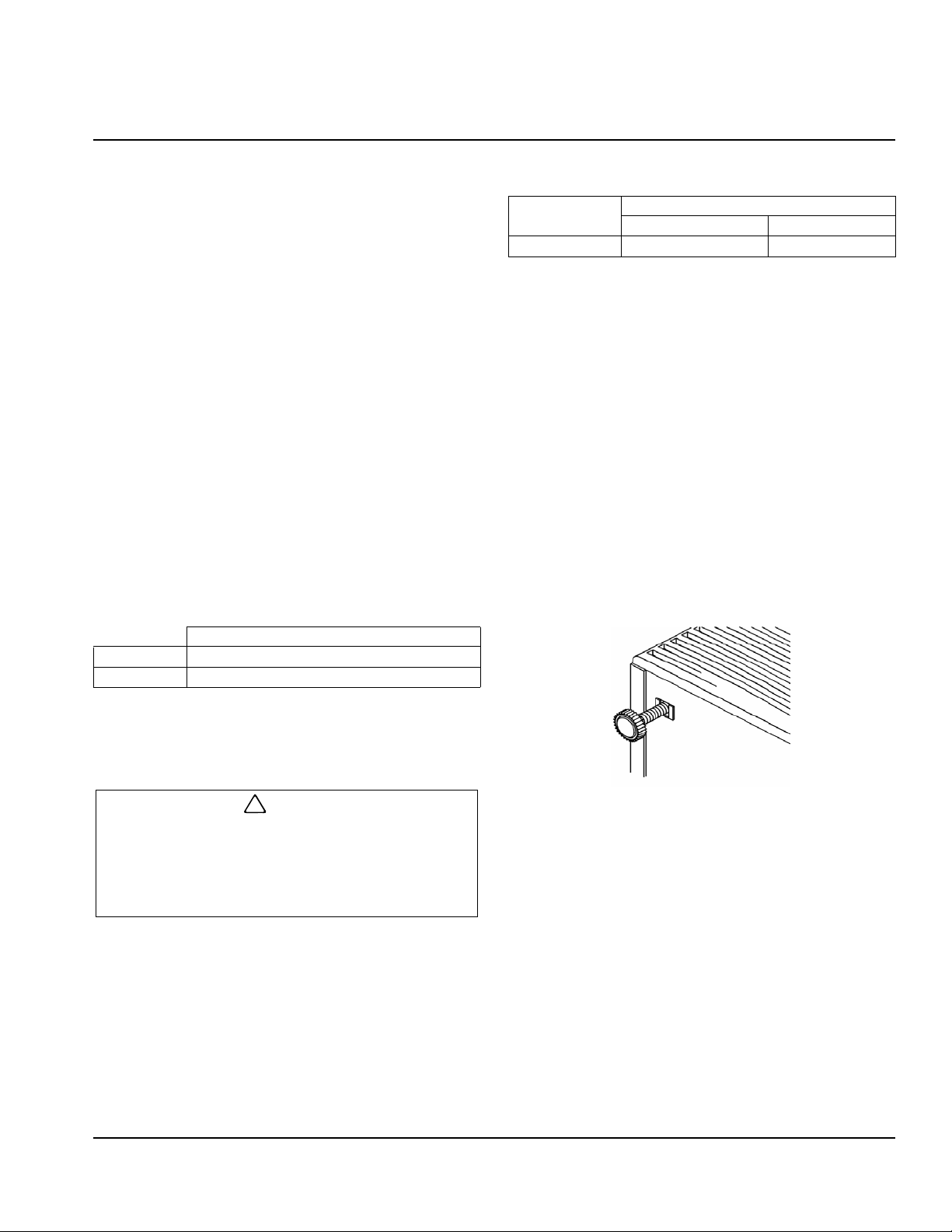
Leveling the Ice Machine
After moving the ice machine into the installation
location, it must be leveled for proper operation. Follow
these steps to level the ice machine:
1. Check the level of the ice machine from front to back
and from side to side.
2. If the ice machine is not level, adjust the leveling
glides on each corner of the base of the ice machine
as necessary.
Self-Contained Air-Cooled
Top/Sides 5" (127 mm)*
Back 5" (127 mm)*
NOTE: The ice machine may be built into a cabin et .
* There is no minimum clearance requirement for the top or left and
right sides of the ice machine. The listed values are recommended
for efficient operation and servicing only.
The ice machine must be protected if it will be
subjected to temperatures below 32°F (0°C).
Failure caused by exposure to freezing
temperatures is not covered by the warranty. See
“Removal from Service/Winterization” Section 4.
Leveling Glide
3. Check the level of the ice machine after each
adjustment of the leveling glides.
4. Repeat steps 2 and 3 until the ice machine is level
from front to back and from side to side.
Part Number 040001360 6/14 5
Page 6
Installation Instructions Section 2
!
Warning
! Warning
! Warning
Important
Important
Electrical Service
All wiring must conform to local, state and national
codes.
Voltage Phase Total Amps
230/50/1 2.6
230/60/1 3.1
115/60/1 5.2
VOLTAGE
The maximum allowable voltage variation is ± 10% of
the rated voltage on the ice machine model/serial
number plate at start-up (when the electrical load is
highest).
The ice machine must be grounded in accordance
with national and local electrical codes.
Never use an extension cord. If an outlet is not
within reach of the ice machine’s power cord, have
a proper amperage outlet wired closer to the ice
machine.
FUSE/CIRCUIT BREAKER
A separate fuse/circuit breaker must be provided for
each ice machine.
NOTE: A disconnect means must be provided for field
wiring.
ELECTRICAL RATING
The electrical rating is used to help select the wire size
of the electrical supply. The wire size (or gauge) also
depends on location, materials used, length of run, etc.,
so it must be determined by a qualified electrician.
Water Service/Drains
WATER SUPPLY
Local water conditions may require treatment of the
water to inhibit scale formation, filter sediment, remove
chlorine, and improve taste and clarity.
If you are installing a Manitowoc Tri-Liminator
water filter system, refer to the Installation
Instructions supplied with the filter system for ice
making water inlet connections.
Follow these guidelines to install water inlet lines:
• Connect to potable water supply only.
• Do not connect the ice machine to a hot water
supply. Be sure all hot water restrictors installed for
other equipment are working. (Check valves on sink
faucets, dishwashers, etc.)
• If water pressure exceeds the maximum
recommended pressure, obtain a water pressure
regulator from your Manitowoc distributor.
• Install a water shut-off valve for both the ice making
and condenser water lines (if applicable).
• Insulate water lines to prevent condensation.
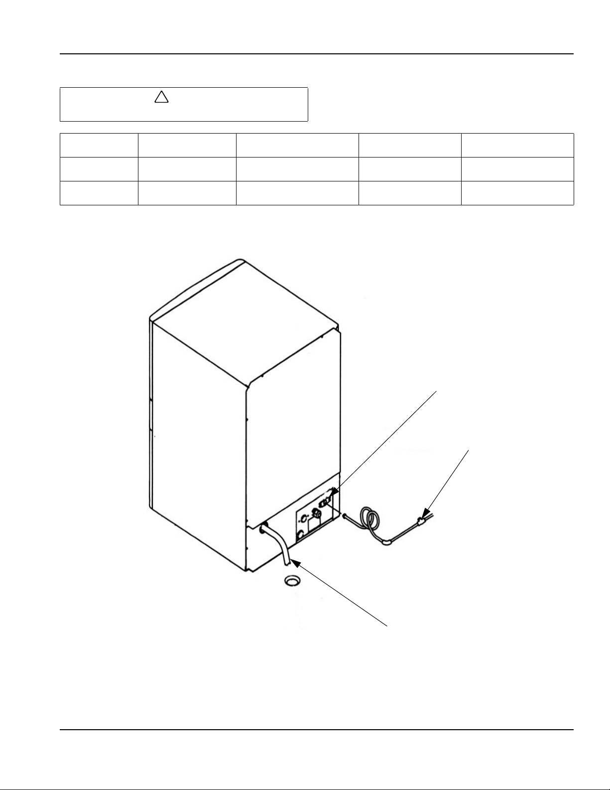
The water inlet line is connected to the water
valve. This valve is located just behind the front
panel of the ice machine.
DRAIN CONNECTIONS
Follow these guidelines when installing drain lines to
prevent drain water from flowing back into the ice
machine and storage bin:
• Drain lines must have a 2.5 cm drop per 1 meter of
run (1.5 inch per 5 feet), and must not create traps.
• The floor drain must be large enough to
accommodate drainage from all drains.
• Insulate the bin drain line to prevent condensation.
6
Part Number 040001360 6/14
Page 7
Section 2 Installation Instructions
!
Caution
WATER SHUTOFF
VALVE
ICE MAKING WATER INLET
TUBING 0.95 cm (3/8") MIN.I.D.
ICE MAKING WATER/BIN
DRAIN 1.59 cm (5/8") MIN.I.D.
WATER SUPPLY AND DRAIN LINE SIZING/CONNECTIONS
Plumbing must conform to state and local codes.
Ice Making
Water Inlet
Ice Making/Bin
Water Drain
1
Min. = Minimum
2
Max. = Maximum
Water
Temperature
0.6°C (33°F) Min.
32.2°C (90°F) Max.
—— ——
1
137.9 kPA (20 psi) Min.
2
551.5 kPA (80 psi) Max.
Water
Pressure
Ice Machine
Fitting
1
2
3/8" male hose
connection
1.59 cm (5/8") inside
diameter flexible hose
Tubing Size Up to Ice
Machine Fitting
0.95 cm (3/8") minimum
inside diameter
1.59 cm (5/8") minimum
inside diameter
Typical Water Supply and Drain Line Sizing and Connections
Part Number 040001360 6/14 7
Page 8
Installation Instructions Section 2
!
Warning
Installation Checklist Before Starting the Ice Machine
All Manitowoc ice machines are factory-operated and
Is the ice machine level?
Has all of the internal packing been removed?
Have all of the electrical and water connection s
been made?
adjusted before shipment. Normally, new inst allations do
not require any adjustment.
To ensure proper operation, follow the Operational
Checks. Starting the ice machine and completing the
Operational Checks are the responsibilities of the owner/
operator.
Adjustments and maintenance procedures outlined in
this manual are not covered by the warranty.
Ice Machine Inspection
Has the supply voltage been tested and
checked against the rating on the nameplate?
Is there proper clearance around the ice
machine for air circulation?
Has the ice machine been installed where
ambient temperatures will remain in the range
of 35° – 110°F (2° – 43°C)?
Check all water fittings and lines for leaks. Also, make
sure the refrigeration tubing is not rubbing or vibrating
against other tubing, panels, etc.
Do not put anything (boxes, etc.) in front of the ice
machine. There must be adequate airflow through and
around the ice machine to maximize ice production and
ensure long component life.
Has the ice machine been installed where the
incoming water temperature will remain in the
range of 33° – 90°F (1° – 32°C)?
Are all electrical leads free from contact with
refrigeration lines and moving equipment?
Has the owner/operator been instructed
regarding maintenance and the use of
Manitowoc Cleaner and Sanitizer?
Has the owner/operator complete d the warranty
registration card?
Has the ice machine and bin been sanitized?
Has this manual been given to the owner/
operator?
PERSONAL INJURY POTENTIAL
Do not operate equipment that has been misused,
abused, neglected, damaged, or altered/modified
from that of original manufactured specifications.
8
Part Number 040001360 6/14
Page 9

Ice Making Sequence of Operation
Section 3
Operation
INITIAL START-UP OR START-UP AFTER AUTOMATIC SHUT-OFF
1. Pressure Equalization
Before the compressor starts the hot gas valve is
energized for 15 seconds to equalize pressures during
the initial refrigeration system start-up.
2. Refrigeration System Start-Up
The compressor starts after the 15-second pressure
equalization, and remains on throughout the entire
Freeze and Harvest Sequences. The hot gas valve
remains on for 5 seconds during initial compressor startup and then shuts off.
At the same time the compressor starts, the condenser
fan motor (air-cooled models) is supplied with power
throughout the entire Freeze and Harvest Sequences.
The fan motor is wired through a fan cycle pressure
control, therefore it may cycle on and off. (The
compressor and condenser fan motor are wired through
the relay . As a result, any time the relay coil is energized,
the compressor and fan motor are supplied with power.)
FREEZE SEQUENCE
3. Prechill
The compressor is on for 30 seconds prior to water flow
to Prechill the evaporator.
4. Freeze
The water pump starts after the 30-second Prechill. An
even flow of water is directed across the evaporator and
into each cube cell, where it freezes.
When sufficient ice has formed, the water flow (not the
ice) contacts the ice thickness probe. After
approximately 7 seconds of continual water contact, the
Harvest Sequence is initiated. The ice machine cannot
initiate a Harvest Sequence until a 6-minute freeze time
has been surpassed.
HARVEST SEQUENCE
5. Harvest
The water pump de-energizes stopping flow over the
evaporator. The rising level of water in the sump trough
diverts water out of the overflow tube, purging excess
minerals from the sump trough. The hot gas valv e also
opens to divert hot refrigerant gas into the evaporator.
The refrigerant gas warms the evaporator causing the
cubes to slide, as a sheet, off the evaporator and into the
storage bin. The sliding sheet of cubes contacts the ice
damper, opening the bin switch.
The momentary opening and re-closing of the bin switch
terminates the Harvest Sequence and returns the ice
machine to the Freeze Sequence (steps 3 - 4).
AUTOMATIC SHUT-OFF
6. Automatic Shut-Off
When the storage bin is full at the end of a Harvest
Sequence, the sheet of cubes fails to clear the ice
damper and will hold it down. After the ice damper is
held open for 7 seconds, the ice machine shuts off. The
ice machine remains off for 3 minutes before it can
automatically restart.
The ice machine remains off until enough ice has been
removed from the storage bin to allow the ice to fall clear
of the damper. As the ice damper swings back to the
operating position, the bin switch re-closes and the ice
machine restarts (steps 1 - 2), provided the 3-minute
delay period is complete.
Part Number 040001360 6/14 9
Page 10
Operation Section 3
WATER
LEVEL
SIPHON
CAP
STANDPIPE
DRAIN
PRESS TO
OPEN
PRESS TO
CLOSE
Operational Checks
GENERAL
Your Manitowoc ice machine was factory-operated and
adjusted before shipment. Normally , a newly inst alled ice
machine does not require any adjustment.
To ensure proper operation, always follow these
Operational Checks when starting the ice machine:
• for the first time
• after a prolonged out of service period
• after cleaning and sanitizing
Routine adjustments and maintenance procedures
outlined in this manual are not covered by the warranty.
SIPHON SYSTEM
To reduce mineral build-up and cleaning frequency, the
water in the sump trough must be purged during each
harvest cycle.
When the water pump de-energizes the level in the
water trough rises above the standpipe st artin g a siphon
action. The siphon action stops when the water level in
the sump trough drops. When the siphon action stops,
the float valve refills the water trough to the correct level.
Siphon System Check
Follow steps 1 through 6 under water level check.
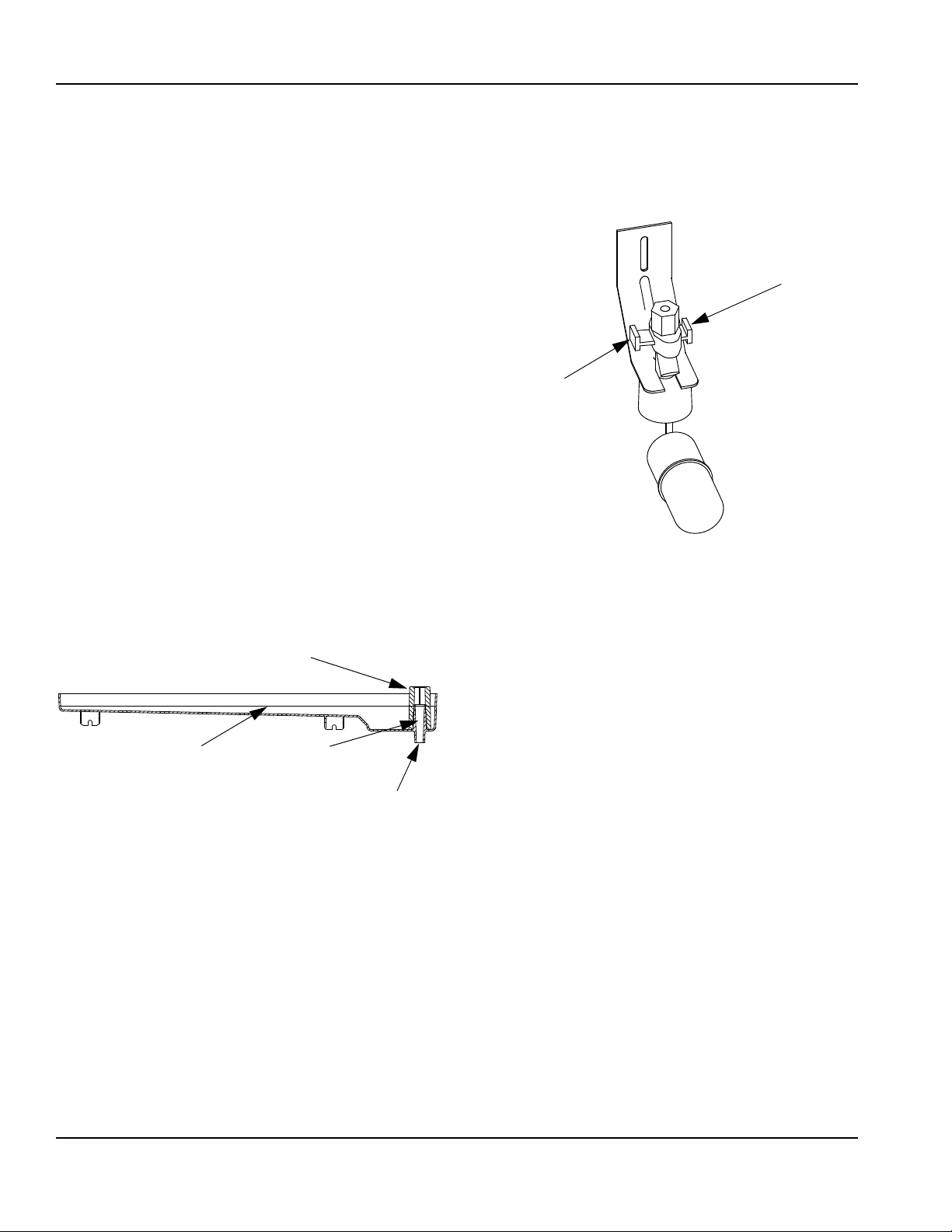
WATER FLOAT VALVE CHECK
Before water will flow into the water trough the float
valve shut-off must be in the OPEN position.
10
Part Number 040001360 6/14
Page 11
Section 3 Operation
SIPHON CAP
SET THE WA TER LEVEL
TO THE LINE IN THE
WATER TROUGH
ADJUSTING SCREW
1/8" ICE BRIDGE THICKNESS
WATER LEVEL CHECK
Check the water level while the ice machine is in the ice
mode and the water pump is running. The correct water
level is 1/4" (6.3 mm) to 3/8" (9.5 mm) below the top of
the standpipe a line in the water trough indicates the
correct level.
The float valve is factory-set for the proper water level. If
adjustments are necessary:
1. Verify the ice machine is level (see page 4-6).
2. Remove the siphon cap from the standpipe.
3. Place the main ON/OFF/WASH toggle switch to the
ON position, and wait until the float valve stops
adding water.
4. Adjust the water level to (1/4" to 3/8" [6.3 to 9.5 mm]
below the standpipe) the line in the water tr ough.
5. Loosen the two screws on the float valve bracket.
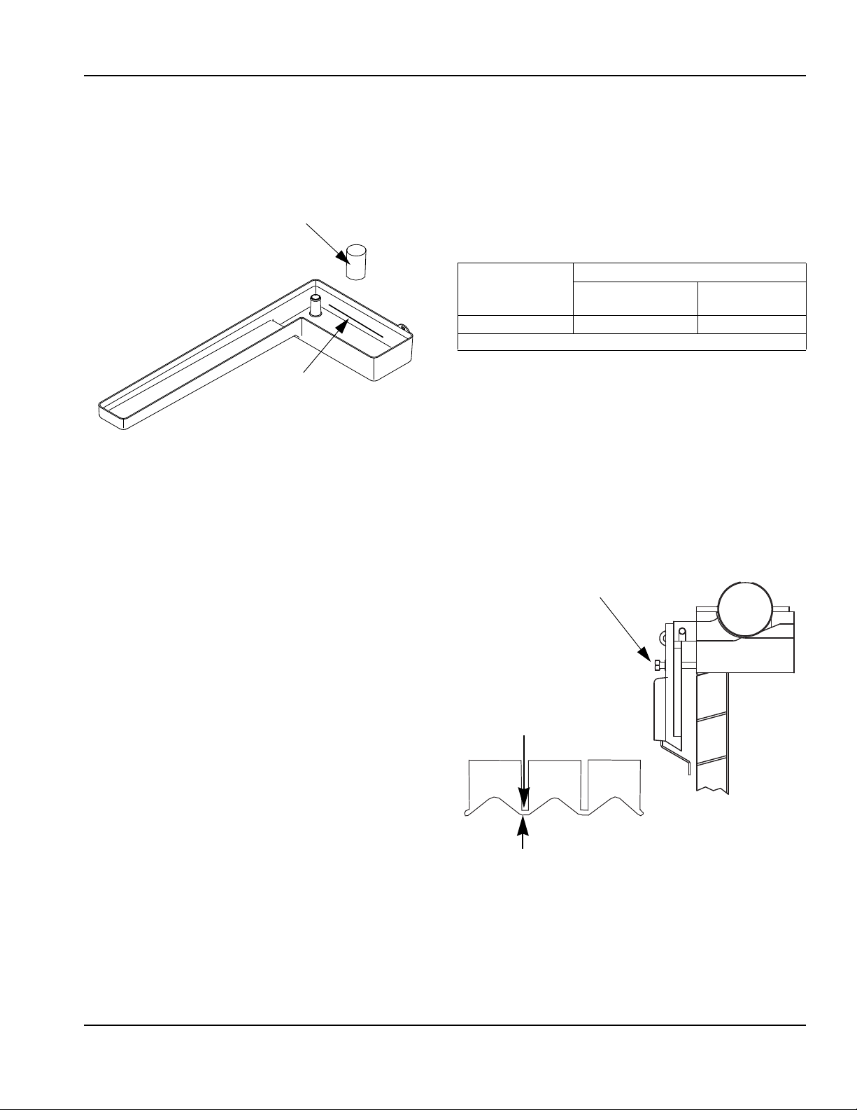
ICE BRIDGE THICKNESS CHECK
NOTE: During shipping and installation the ice thickness
probe may shift, requiring further adjustment to achieve
the rated energy efficiency and production. The ice
weight per cycle must be within the minimum and
maximum for your ice machine series. Capture and
weigh the ice from the second freeze/harvest cycle. The
target weight is the middle of the minimum and
maximum weight in the chart below.
Series
Ice Machine
QM45 1.1 lbs 1.3 lbs
Target weight is the middle of the minimum and maximum weight.
Ice Weight From One Cycle
Minimum Ice
Weight
Maximum Ice
Weight
The ice thickness probe is factory-set to maintain th e ice
bridge thickness at 1/8" (3.2 mm).
1. Inspect the bridge connecting the cubes. It should
be about 1/8" (3.2 mm) thick.
2. If adjustment is necessary, turn the ice thickness
probe adjustment screw clockwise to increase
bridge thickness, or counterclockwise to decrease
bridge thickness.
NOTE: Turning the adjustment 1/3 of a turn will change
the ice thickness about 1/16" (1.5 mm).
6. Raise or lower the float valve assembly as
necessary, then tighten the screws.
7. Move the main ON/OFF/ WASH toggle switch to the
OFF position. The water level in the trough will rise
above the standpipe and run down the drain.
8. Replace the siphon cap on the standpipe, and verify
water level and siphon action by repeating steps 3
through 5.
Part Number 040001360 6/14 11
Make sure the ice thickness probe wire and the brac ket
do not restrict movement of the probe.
Page 12
Section 4
!
Caution
!
Caution
!
Warning
!
Caution
!
Warning
Maintenance
Interior Cleaning and Sanitizing
GENERAL
Clean and sanitize the ice machine every six months for
efficient operation. If the ice machine requires more
frequent cleaning and sanitizing, consult a qualified
service company to test the water quality and
recommend appropriate water treatment.
The ice machine must be taken apart for cleaning and
sanitizing.
Use only Manitowoc approved Ice Machine Cleaner
(part number 94-0546-3) and Sanitizer (part
number 94-0565-3). It is a violation of Federal law
to use these solutions in a manner inconsistent with
their labeling. Read and understand all labels
printed on bottles before use.
CLEANING AND SANITIZING PROCEDURE
Do not mix Ice Machine Cleaner and Sanitizer
solutions together. It is a violation of Federal law to
use these solutions in a manner inconsistent with
their labeling.
Step 1 Set the toggle switch to the OFF position after
ice falls from the evaporator at the end of a Harvest
cycle. Or, set the switch to the OFF position and allow
the ice to melt off the evaporator.
Never use anything to force ice from the evaporator.
Damage may result.
Step 2 Remove all ice from the bin.
Step 3 T o st art a cleaning cycle, move the toggle switch
to the WASH position.
Step 4 Add the proper amount of Manitowoc Ice
Machine Cleaner to the water trough.
Model Amount of Cleaner
QM45 1.5 ounces (45 ml)
Step 5 Wait until the clean cycle is complete
(approximately 22 minutes) then place the toggle switch
in the OFF position, disconnect power and water
supplies to the ice machine.
Disconnect electric power to the ice machine at the
electric switch box before proceeding.
Wear rubber gloves and safety goggles ( an d/or face
shield) when handling Ice Machine Cleaner or
Sanitizer.
Ice machine cleaner is used to remove lime scale and
mineral deposits. Ice machine sanitizer disinfects and
removes algae and slime.
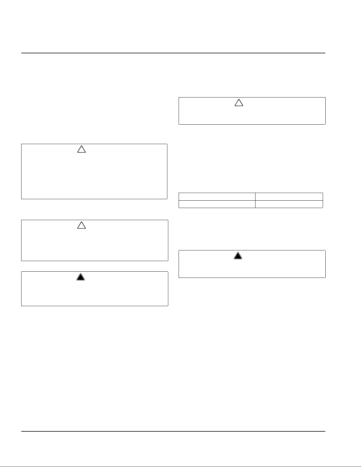
Step 6 Remove parts for cleaning.
A. Remove Two Thumbscrews and Water Pump
Cover (When Used).
B. Remove the Vinyl Hose Connecting the
Water Pump and Water Distribution Tube
C. Remove Water Pump
• Disconnect the water pump power cord
• Loosen the screws securing the pumpmounting bracket to the bulkhead
• Lift the pump and bracket assembly off the
mounting screws..
12 Part Number 040001360 6/14
Page 13
Section 4 Maintenance
DO NOT SOAK
WATER PUMP MOTOR IN
CLEANER OR SANITIZER
SOLUTIONS
When Used - REMOVE
THUMBSCREWS AND
WATER PUMP COVER
!
Caution
1. LIFT UP
2. SLIDE BACK
3. SLIDE TO RIGHT
DISTRIBUTION
TUBE
THUMBSCREW
THUMBSCREW
LOCATING
PIN
3
2
1
.
Water Pump Removal
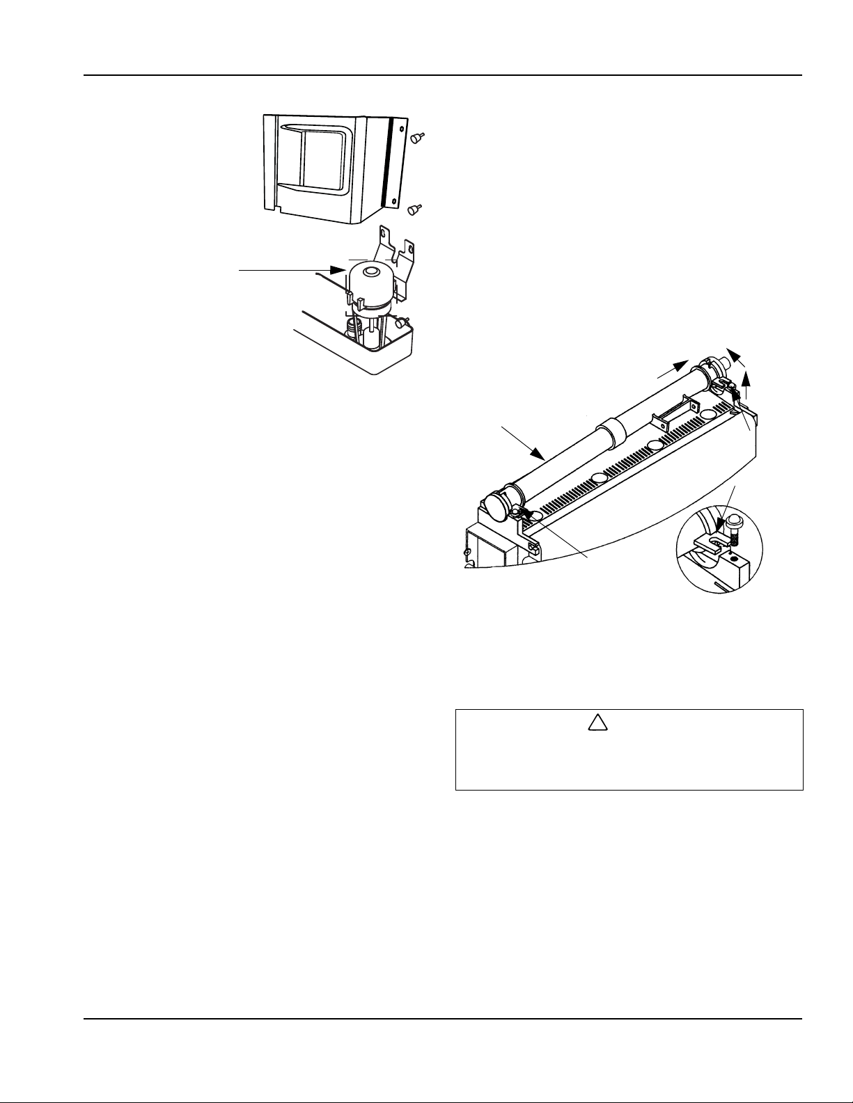
D. Remove the Ice Thickness Probe
Ice Thickness Probe Cleaning
• Mix a solution of Manitowoc ice machine cleaner and
water (2 ounces of cleaner to 16 ounces of water) in
a container.
• Soak the ice thickness probe a minimum of 10
minutes.
Clean all ice thickness probe surfaces and verify the ice
thickness probe cavity is clean. Rinse thoroughly with
clean water , then dry comple tely. Incomplete rinsing and
drying of the ice thickness probe can cause premature
harvest.
E. Remove the Water Distribution Tube
NOTE: At this point, the ice thickness probe can easily
be cleaned. If complete removal is desired follow the ice
thickness probe wire to the bulkhead grommet (exit
point) in the back wall. Pop the bulkhead grommet out of
the back wall by inserting fingernails or a flat object
between the back wall and the grommet and prying
forward. Pull the bulkhead grommet and wire forward
until the connector is accessible, then disconnect the
wire lead from the connector.
• Compress the side of the ice thickness probe
near the top hinge pin and remove it from the
bracket.
• Loosen the two thumbscrews, which secure the
distribution tube.
• Lift the right side of the distribution tube up off the
locating pin, then slide it back and to the right.
Do not force this removal. Be sure the locating pin is
clear of the hole before sliding the distribution tube
out.
Part Number 040001360 6/14 13
Page 14
Maintenance Section 4
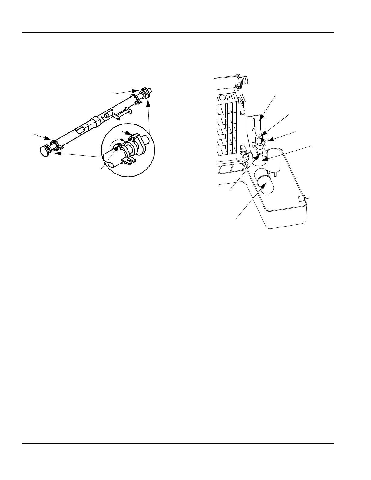
INNER TUBE
TAB
KEYWAY
INNER TUBE
FLOAT VALVE
BRACKET
COMPRESSION
FITTING
CAP AND
FILTER SCREEN
SHUT-OFF VALVE
SPLASH SHIELD
FLOAT
Disassembly
• Twist both of the inner tube ends until the tabs line up
with the keyways.
• Pull the inner tube ends outward.
F. Remove the Float Valve
• Turn the splash shield counterclockwise one or two
turns.
• Pull the float valve forward and off the mounting
bracket.
• Disconnect the water inlet tube from the float valve at
the compression fitting.
• Remove the cap and filter screen for cleaning.
14
Part Number 040001360 6/14
Page 15

Section 4 Maintenance
REMOVE
SIPHON TUBE
UPPER
THUMBSCREW
LOWER
THUMBSCREWS
G. Remove the Water Trough
• Apply downward pressure on the siphon tube and
remove from the bottom of the water trough.
• Remove the upper thumbscrew.
• While supporting the water trough remove the two
thumbscrews from beneath the water trough.
• Remove the water trough from the bin area.
H. Remove the ice damper.
• Grasp ice damper and apply pressure toward the l ef t
hand mounting bracket.
• Apply pressure to the right hand mounting bracket
with thumb.
• Pull ice damper forward when the right hand ice
damper pin disengages.
Installation
• Place ice damper pin in left hand mounting bracket
and apply pressure toward the left hand mounting
bracket.
• Apply pressure to the right hand mounting bracket
with thumb.
• Push ice damper toward evaporator until right hand
damper pin engages.
Part Number 040001360 6/14 15
Page 16

Maintenance Section 4
TRACK SLOT
SLIDE DOOR
FORWARD
STOP TAB
PRESS DOWN
TO RELEASE
DOOR
I. Remove the Bin Door
• Grasp the rear of the bin door and pull bin door
forward approximately 5" (13 cm).
• Slide bin door to the rear while applying upward
pressure (The rear door pins will ride up into the track
slot and slide backward to the stop tab).
• While applying pressure against the bin door pull
down on the rear of each bin door track until the door
pins clear the stop tabs.
• Slide the rear door pins off the end and then below
the door track. Slide bin door forward allowing the
back of the door to lower into the bin. Continue
forward with the bin door until the front pins bottom
out in the track.
• Lift right side of door until the front pins clear the
track, then remove door from bin.
Step 7 Mix a solution of cleaner and warm water .
Depending on the amount of mineral buildup, a larger
quantity of solution may be required. Use the ratio in the
table below to mix enough solution to thoroughly clean
all parts.
Solution Type Water Mixed with
Cleaner 1 gal. (4 l) 16 oz (500 ml) cleaner
Step 8 Use 1/2 of the cleaner/water solution to clean all
components. The cleaner solution will foam when it
contacts lime scale and mineral deposits; once the
foaming stops use a soft bristle brush, sponge or cloth
(not a wire brush) to carefully clean the parts. Soak the
parts for 5 minutes (15 – 20 minutes for heavily scaled
parts). Rinse all components with clean water.
Step 9 While components are soaking, use 1/2 of the
cleaner/water solution to clean all foodzone surfaces of
the ice machine and bin. Use a nylon brush or cloth to
thoroughly clean the following ice machine areas:
• Evaporator plastic parts – including top, bottom and
sides
• Bin bottom, sides and top
Rinse all areas thoroughly with clean water.
Step 10 Mix a solution of sanitizer and warm water.
Solution Type Water Mixed With
Sanitizer 6 gal. (23 l) 4 oz (120 ml) sanitizer
Step 11 Use 1/2 of the sanitizer/water solution to
sanitize all removed components. Use a cloth or sponge
to liberally apply the solution to all surfaces of the
removed parts or soak the removed parts in the
sanitizer/water solution. Do not rinse parts after
sanitizing.
16
Part Number 040001360 6/14
Page 17

Section 4 Maintenance
!
Warning
Step 12 Use 1/2 of the sanitizer/water solution to
sanitize all foodzone surfaces of the ice machine and
bin. Use a cloth or sponge to liberally apply th e solu tion.
When sanitizing, pay particular attention to the following
areas:
• Evaporator plastic parts - including top, bottom and
sides
• Bin bottom, sides and top
Do not rinse the sanitized areas.
Step 13 Replace all removed components.
Step 14 Reapply power and water to the ice machine
and place the toggle switch in the WASH position.
Step 15 Add the proper amount of Manitowoc Ice
Machine Sanitizer to the water trough.
Model Amount of Sanitizer
QM45 1.5 ounces (45 ml)
Step 16 Wait until the sanitize cycle is complete
(approximately 22 minutes) then place the toggle switch
in the OFF position, disconnect power and water
supplies to the ice machine.
Step 19 Use 1/2 of the sanitizer/water solution to
sanitize all removed components. Use a cloth or sponge
to liberally apply the solution to all surfaces of the
removed parts or soak the removed parts in the
sanitizer/water solution. Do not rinse parts after
sanitizing.
Step 20 Use 1/2 of the sanitizer/water solution to
sanitize all foodzone surfaces of the ice machine and
bin. Use a cloth or sponge to liberally apply the solutio n.
When sanitizing, pay particular attention to the following
areas:
• Evaporator plastic parts - including top, bottom and
sides
• Bin bottom, sides and top
Do not rinse the sanitized areas.
Step 21 Replace all removed components.
Step 22 Reapply power and water to the ice machine
and place the toggle switch in the ICE position.
Exterior Cleaning
Clean the area around the ice machine as often as
necessary to maintain cleanliness and efficient
operation.
Disconnect electric power to the ice machine at the
electric switch box before proceeding.
Step 17 Repeat step 6 to remove parts for hand
sanitizing.
Step 18 Mix a solution of sanitizer and warm water.
Solution Type Water Mixed With
Sanitizer 6 gal. (23 l) 4 oz (120 ml) sanitizer
Sponge any dust and dirt off the outside of the ice
machine with mild soap and water. Wipe dry with a
clean, soft cloth.
A commercial grade stainless steel cleaner/polish can
be used as necessary.
Part Number 040001360 6/14 17
Page 18

Maintenance Section 4
!
Warning
!
Warning
!
Caution
!
Caution
Cleaning the Condenser
Disconnect electric power to the ice machine at
the electric service switch before cleaning the
condenser.
A dirty condenser restricts airflow, resulting in
excessively high operating temperatures. This reduces
ice production and shortens component life. Clean the
condenser at least every six months. Follow the steps
below.
The condenser fins are sharp. Use care when
cleaning them.
1. The washable aluminum filter on self-contained ice
machines is designed to catch dust, dirt, lint and
grease. This helps keep the condenser clean. Clean
the filter with a mild soap and water solution.
2. Clean the outside of the condenser with a soft brush
or a vacuum with a brush attachment. Clean from
top to bottom, not side to side. Be careful not to
bend the condenser fins.
3. Shine a flashligh t th ro ug h th e co nd en se r to check
for dirt between the fins. If dirt remains: Blow
compressed air through the condenser fins from the
inside. Be careful not to bend the fan blades.
4. Use a commercial condenser coil cleaner. Follow
the directions and cautions supplied with the
cleaner.
Removal from Service/Winterization
Special precautions must be taken if the ice machine is
to be removed from service for an extended period of
time or exposed to ambient temperatures of 32°F (0°C)
or below.
If water is allowed to remain in the ice machine in
freezing temperatures, severe damage to some
components could result. Damage of this nature i s
not covered by the warranty.
Follow the applicable procedure below.
1. Disconnect the electric power at the circuit breaker
or the electric service switch.
2. Turn off the water supply.
3. Remove the water from the water trough.
4. Disconnect and drain the incoming ice-making water
line at the rear of the ice machine.
5. Blow compressed air in both the incoming water and
the drain openings in the rear of the ice machine
until no more water comes out of the inlet water lines
or the drain.
6. Make sure water is not trapped in any of the water
lines, drain lines, distribution tubes, etc.
5. Straighten any bent condenser fins with a fin comb.
6. Carefully wipe off the fan blades and motor with a
soft cloth. Do not bend the fan blades. If the fan
blades are excessively dirty, wash with warm, soapy
water and rinse thoroughly.
If you are cleaning the condenser fan blades with
water, cover the fan motor to prevent water
damage.
18
Part Number 040001360 6/14
Page 19

Section 5
Customer Support
Checklist
If a problem arises during operation of your ice machine, follow the checklist below before calling service. Routine
adjustments and maintenance procedures are not covered by the warranty.
Problem Possible Cause To Correct
Ice machine does not operate. No electrical power to the ice machine. Replace the fuse/reset the breaker/turn on
the main switch/plug power cord into
receptacle.
Ice machine stops, and can be
restarted by moving the toggle
switch to OFF and back to ICE.
Ice machine does not release ice or
is slow to harvest.
Ice machine does not cycle into
harvest mode.
Ice quality is poor
(soft or not clear).
ON/OFF/ WASH toggle switch set
improperly.
Damper in open position (down). Damper must be in upright position and
Safety limit feature stopping the ice machi ne. Refer to “Safety Limit Feature” on the next
Ice machine is dirty. Clean and sanitize the ice machine.
Ice machine is not level. Level the ice machine.
Low air temperature around ice machine. Air temperature must be at least 35°F
The six-minute freeze time lock-in has not
expired yet.
Ice thickness probe is dirty. Clean and sanitize the ice machine.
Ice thickness probe wire is disconnected. Connect the wire.
Ice thickness probe is out of adjustment. Adjust the ice thickness probe.
Uneven ice fill (thin at top of evaporator). See “Shallow or Incomplete Cubes” on the
Poor incoming water quality. Contact a qualified service company to
Water filtration is poor. Replace the filter.
Ice machine is dirty. Clean and sanitize the ice machine.
Water siphon is not working. Check the water siphon system.
Water softener is working improperly
(if applicable).
Move the toggle switch to the ON position.
capable of swinging freely.
page.
(2°C).
Wait for freeze lock-in to expire.
next page.
test the quality of the incoming water and
make appropriate filter recommendations.
Repair the water softener.
Continued on next page...
Part Number 040001360 6/14 19
Page 20

Customer Support Section 5
Problem Possible Cause To Correct
Ice machine produces shallow or
incomplete cubes, or the ice fill
pattern on the evaporator is
incomplete.
Low ice capacity. Water float valve filter screen is dirty. Remove and clean the filter screen.
Ice thickness probe is out of adjustment. Adjust the ice thickness probe.
Water trough level is to high or too low. Check the water level.
Water float valve filter screen is dirty. Remove and clean the filter screen.
Water filtration is poor. Replace the filter.
Hot incoming water. Connect the ice machine to a cold water
supply.
Water float valve is not working. Remove the water float valve and clean it.
Incorrect incoming water pressure. Water pressure must be 20-80 psi (137.9 -
551.5 kPA).
Ice machine is not level. Level the ice machine.
Incoming water supply is shut off. Open the water service valve.
Water float valve stuck open or leaking. Remove the water float valve and clean it.
The condenser is dirty. Clean the condenser.
High air temperature around ice machine. Air temperature must not exceed 110°F
(43°C).
Inadequate clearance around the ice
machine.
Objects stacked around ice machine,
blocking airflow to condenser.
Provide adequate clearance.
Remove items blocking airflow.
Safety Limit Feature
In addition to the standard safety controls, your
Manitowoc ice machine features built-in safety limits that
will stop the ice machine if conditions arise which could
cause a major component failure.
Before calling for service, re-start the ice machine using
the following procedure:
1. Move the ON/OFF/ WASH switch to OFF and then
back to ON.
A. If the safet y limit feat ur e ha s sto pp ed the ice
machine, it will restart after a short delay.
Proceed to step 2.
B. If the ice mach in e do es not restart, see “Ice
machine does not operate” on the previous
page.
2. Allow the ice machine to run to determine if the
condition is reoccurring.
A. If the ice machine stops again, the condition has
reoccurred. Call for service.
B. If the ice machine continues to run, the condition
has corrected itself. Allow the ice machine to
continue running.
20
Part Number 040001360 6/14
Page 21

Section 5 Customer Support
Commercial Ice Machine Warranty
Manitowoc Ice, Inc. (hereinafter referred to as the “COMPANY”) warrants for a period of thirty-six months from the
installation date (except as limited below) that new ice machines manufactured by the COMPANY shall be free of
defects in material or workmanship under normal and proper use and maintenance as specified by the COMPANY
and upon proper installation and start-up in accordance with the instruction manual supplied with the ice machine.
The COMP ANY’s warranty hereunder with respect to the compressor shall apply for an additional twenty-four months,
excluding all labor charges, and with respect to the evaporator for an additional twenty-four months, including labor
charges.
The obligation of the COMPANY under this warranty is limited to the repair or replacement of parts, components, or
assemblies that in the opinion of the COMPANY are defective. This warranty is further limited to the cost of parts,
components or assemblies and standard straight time labor charges at the servicing location.
Time and hourly rate schedules, as published from time to time by the COMPANY, apply to all service procedures.
Additional expenses including without limitation, travel time, overtime premium, material cost, accessing or removal of
the ice machine, or shipping are the responsibility of the owner, along with all maintenance, adjustments, cleaning,
and ice purchases. Labor covered under this warran ty must be performed by a COMPANY Contracted Service
Representative or a refrigeration service agency as qualified and authorized by the COMPANY’ s local Distributor . The
COMP ANY’ s liability under this warranty shall in no event be greater than the actual purchase price pa id by customer
for the ice machine.
The foregoing warranty shall not apply to (1) any part or assembly that has been altered, modified, or changed; (2)
any part or assembly that has been subjected to misuse, abuse, neglect, or accidents; (3) any ice machine that has
been installed and/or maintained inconsistent with the technical instructions provided by the COMP ANY; or (4) any ice
machine initially installed more than five years from the serial number production da te. This warranty shall not apply if
the Ice Machine’s refrigeration system is modified with a condenser, heat reclaim device, or parts and assemblies
other than those manufactured by the COMPANY, unless the COMPANY approves these modifications for specific
locations in writing.
THIS WARRANTY IS IN LIEU OF ALL OTHER WARRANTIES OR GUARANTEES OF ANY KIND, EXPRESSED
OR IMPLIED, INCLUDING ANY IMPLIED WARRANTY OF MERCHANTABILITY OR FITNESS FOR A
PARTICULAR PURPOSE. In no event shall the COMPANY be liable for any special, indirect, incidental or
consequential damages. Upon the expiration of the warranty period, the COMPANY’s liability und er this warranty shall
terminate. The foregoing warranty shall constitute the sole liability of the COMPANY and the exclusive remedy of the
customer or user.
To secure prompt and continuing warranty service, the warranty registration card must be completed and sent to the
COMPANY within five (5) days from the installation date.
Complete the following and retain for your record:
Distributor/Dealer ______________________________________________________________________________
Model Number ________________________________ Serial Number __________________________________
Installation Date _______________________________________________________________________________
MANITOWOC ICE, INC.
2110 So. 26th St., P.O. Box 1720, Manitowoc, WI 54221-1720
Telephone: 920-682-0161 • Fax: 920-683-7585
Web Site - www.manitowocice.com
Form 80-0375-3 Rev. 01-02
Part Number 040001360 6/14 21
Page 22

Customer Support Section 5
Residential Ice Machine Limited Warranty
WHAT DOES THIS LIMITED WARRANTY COVER?
Subject to the exclusions and limitations below, Manitowoc
Foodservice (“Manitowoc”) warrants to the original consumer
that any new ice machine manufactured by Manitowoc (the
“Product”) shall be free of defects in material or workmanship
for the warranty period outlined below under normal use and
maintenance, and upon proper installation and start-up in
accordance with the instruction manual supplied with the
Product.
HOW LONG DOES THIS LIMITED WARRANTY LAST?
Product Covered Warranty Period
Ice Machine Twelve (12) months
from the sale date
WHO IS COVERED BY THIS LIMITED WARRANTY?
This limited warranty only applies to the original consumer of
the Product and is not transferable.
WHAT ARE MANITOWOC ICE’S OBLIGATIONS UNDER
THIS LIMITED WARRANTY?
If a defect arises and Manitowoc receives a valid warranty
claim prior to the expiration of the warranty period, Manitowoc
shall, at its option: (1) repair the Product at Manitowoc’s cost,
including standard straight time labor charges, (2) replace the
Product with one that is new or at least as functionally
equivalent as the original, or (3) refund the purchase price for
the Product. Replacement parts are warranted for 90 days or
the balance of the original warranty period, whichever is
longer. The foregoing constitutes Manitowoc’s sole obligation
and the consumer’s exclusive remedy for any breach of this
limited warranty. Manitowoc’s liability under this limited
warranty is limited to the purchase price of Product. Additional
expenses including, without limitation, service travel time,
overtime or premium labor charges, accessing or removing
the Product, or shipping are the responsibility of the
consumer.
WHAT IS NOT COVERED?
This limited warranty does not cover, and you are solely
responsible for the costs of: (1) periodic or routine
maintenance, (2) repair or replacement of the Product or parts
due to normal wear and tear, (3) defects or damage to the
Product or parts resulting from misuse, abuse, neglect, or
accidents, (4) defects or damage to the Product or parts
resulting from improper or unauthorized alterations,
modifications, or changes; and (5) defects or damage to any
Product that has not been installed and/or maintained in
accordance with the instruction manual or technical
instructions provided by Manitowoc. To the extent that
warranty exclusions are not permitted under some state laws,
these exclusions may not apply to you.
EXCEPT AS STATED IN THE FOLLOWING SENTENCE, THIS LIMITED
WARRANTY IS THE SOLE AND EXCLUSIVE WARRANTY OF
MANITOWOC WITH REGARD TO THE PRODUCT. ALL IMPLIED
ARRANTIES ARE STRICTLY LIMITED TO THE DURATION OF THE
W
LIMITED WARRANTY APPLICABLE TO THE PRODUCTS AS STATED
ABOVE, INCLUDING BUT NOT LIMITED TO, ANY WARRANTY OF
ERCHANTABILITY OR OF FITNESS FOR A PARTICULAR
M
PURPOSE.
Some states do not allow limitations on how long an implied
warranty lasts, so the above limitation may not apply to you.
IN NO EVENT SHALL MANITOWOC OR ANY OF ITS AFFILIATES BE
IABLE TO THE CONSUMER OR ANY OTHER PERSON FOR ANY
L
INCIDENTAL, CONSEQUENTIAL OR SPECIAL DAMAGES OF ANY
KIND (INCLUDING, WITHOUT LIMITATION, LOSS PROFITS,
EVENUE OR BUSINESS) ARISING FROM OR IN ANY MANNER
R
CONNECTED WITH THE PRODUCT, ANY BREACH OF THIS LIMITED
WARRANTY, OR ANY OTHER CAUSE WHATSOEVER, WHETHER
ASED ON CONTRACT, TORT OR ANY OTHER THEORY OF
B
LIABILITY.
Some states do not allow the exclusion or limitation of
incidental or consequential damages, so the above limitation
or exclusion may not apply to you.
HOW TO OBTAIN WARRANTY SERVICE
To obtain warranty service or information regarding your
Product, please contact us at:
MANITOWOC FOODSERVICE
2110 So. 26th St.
P.O. Box 1720,
Manitowoc, WI 54221-1720
Telephone: 920-682-0161 Fax: 920-683-7585
www.manitowocice.com
22
HOW STATE LAW APPLIES
This limited warranty gives you specific legal rights, and you
may also have rights that vary from state to state or from one
jurisdiction to another.
REGISTRATION CARD
To secure prompt and continuing warranty service, this
warranty registration card must be completed and sent to
Manitowoc within thirty (30) days from the sale date. Complete
the following registration card and send it to Manitowoc.
Part Number 040001360 6/14
Page 23

Section 1
Généralités 25
Références des modèles . . . . . . . . . . . . . . . . . . . . . . . . . . . . . . . . . . . . . . . . . . . . . 25
Accessoires . . . . . . . . . . . . . . . . . . . . . . . . . . . . . . . . . . . . . . . . . . . . . . . . . . . . . . . 25
Système de filtration d’eau Tri-Liminator . . . . . . . . . . . . . . . . . . . . . . . . . . . . . 25
Nettoyant et désinfectant Manitowoc . . . . . . . . . . . . . . . . . . . . . . . . . . . . . . . . 25
Section 2
Instructions d’installation 26
Emplacement de la machine à glaçons . . . . . . . . . . . . . . . . . . . . . . . . . . . . . . . . . 26
Machine à glaçons Chaleur de rejet . . . . . . . . . . . . . . . . . . . . . . . . . . . . . . . . . . . . 26
Niveler la machine à glaçons . . . . . . . . . . . . . . . . . . . . . . . . . . . . . . . . . . . . . . . . . 26
Alimentation électrique . . . . . . . . . . . . . . . . . . . . . . . . . . . . . . . . . . . . . . . . . . . . . . 27
Tension . . . . . . . . . . . . . . . . . . . . . . . . . . . . . . . . . . . . . . . . . . . . . . . . . . . . . . . 27
Fusible/Disjoncteur . . . . . . . . . . . . . . . . . . . . . . . . . . . . . . . . . . . . . . . . . . . . . . 27
Caractéristiques électriques . . . . . . . . . . . . . . . . . . . . . . . . . . . . . . . . . . . . . . . 27
Service d’eau/Évacuations d’eau . . . . . . . . . . . . . . . . . . . . . . . . . . . . . . . . . . . . . . 27
Alimentation en eau . . . . . . . . . . . . . . . . . . . . . . . . . . . . . . . . . . . . . . . . . . . . . 27
Raccordements d’évacuation . . . . . . . . . . . . . . . . . . . . . . . . . . . . . . . . . . . . . . 27
Dimensionnement/Raccordement des conduites d’alimentation en eau
et d’évacuation . . . . . . . . . . . . . . . . . . . . . . . . . . . . . . . . . . . . . . . . . . . . . . . . . 28
Liste de vérification d’installation . . . . . . . . . . . . . . . . . . . . . . . . . . . . . . . . . . . . . 29
Avant la mise en marche de la machine à glaçons . . . . . . . . . . . . . . . . . . . . . . . 29
Inspection de la machine à glaçons . . . . . . . . . . . . . . . . . . . . . . . . . . . . . . . . . . . . 29
Table des matières
Section 3
Fonctionnement
Séquence de fabrication des glaçons . . . . . . . . . . . . . . . . . . . . . . . . . . . . . . . . . . 30
Mise en marche initiale ou mise en marche après arrêt automatique . . . . . . . 30
Séquence de congélation . . . . . . . . . . . . . . . . . . . . . . . . . . . . . . . . . . . . . . . . . 30
Séquence de démoulage . . . . . . . . . . . . . . . . . . . . . . . . . . . . . . . . . . . . . . . . . 30
Arrêt automatique . . . . . . . . . . . . . . . . . . . . . . . . . . . . . . . . . . . . . . . . . . . . . . . 30
Vérifications opérationnelles . . . . . . . . . . . . . . . . . . . . . . . . . . . . . . . . . . . . . . . . . 31
Généralités . . . . . . . . . . . . . . . . . . . . . . . . . . . . . . . . . . . . . . . . . . . . . . . . . . . . 31
Système de siphonnement . . . . . . . . . . . . . . . . . . . . . . . . . . . . . . . . . . . . . . . . 31
Contrôle du robinet à flotteur d’eau . . . . . . . . . . . . . . . . . . . . . . . . . . . . . . . . . . 31
Contrôle du niveau d’eau . . . . . . . . . . . . . . . . . . . . . . . . . . . . . . . . . . . . . . . . . 32
Contrôle de l’épaisseur du pont de glace . . . . . . . . . . . . . . . . . . . . . . . . . . . . . 32
Part Number 040001360 6/14 23
Page 24

Section 4
Entretien
Section 5
Service clientèle
Table des matières (suite)
Nettoyage et désinfection intérieurs . . . . . . . . . . . . . . . . . . . . . . . . . . . . . . . . . . . . 33
Généralités . . . . . . . . . . . . . . . . . . . . . . . . . . . . . . . . . . . . . . . . . . . . . . . . . . . . 33
Procédure de nettoyage et de désinfection . . . . . . . . . . . . . . . . . . . . . . . . . . . . 33
Nettoyage extérieur . . . . . . . . . . . . . . . . . . . . . . . . . . . . . . . . . . . . . . . . . . . . . . . . . 38
Nettoyage du condenseur . . . . . . . . . . . . . . . . . . . . . . . . . . . . . . . . . . . . . . . . . . . . 39
Mise hors service/Hivérisation . . . . . . . . . . . . . . . . . . . . . . . . . . . . . . . . . . . . . . . . 39
Liste de vérification . . . . . . . . . . . . . . . . . . . . . . . . . . . . . . . . . . . . . . . . . . . . . . . . . 40
Fonction de limite de sécurité . . . . . . . . . . . . . . . . . . . . . . . . . . . . . . . . . . . . . . . . . 41
Garantie commerciale de la machine à glaçons . . . . . . . . . . . . . . . . . . . . . . . . . . 42
Garantie limitée résidentielle de la machine à glaçons . . . . . . . . . . . . . . . . . . . . 43
24 Part Number 040001360 6/14
Page 25

Section 1
Généralités
Références des modèles
Le présent manuel s’applique aux modèles suivants :
QM45A 115/60/1
QM45A 230/50/1
QM45A 230/60/1
Accessoires
Contacter le distributeur Manitowoc pour obtenir ces
accessoires en option :
SYSTÈME DE FILTRATION D’EAU TRI-LIMINATOR
Conçus spécifiquement pour les machines à glaçons
Manitowoc, les filtres à eau Tri-Liminator sont une
méthode efficace, fiable et abordable pour empêcher la
formation de tartre, filtrer les sédiments et éliminer le
goût et l’odeur du chlore.
NETTOYANT ET DÉSINFECTANT MANITOWOC
Le nettoyant et le désinfectant pour machines à glaçons
Manitowoc sont disponibles en bouteilles pratiques de
473 ml (16 oz) et de 3,78 l (1 gallon). Ce nettoyant et ce
désinfectant sont les seuls produits approuvés pour les
machines Manitowoc.
Référence du nettoyant Référence du désinfectant
16 oz 94-0456-3 16 oz 94-0565-3
1 Gallon 94-0580-3 1 Gallon 94-0581-3
Part Number 040001360 6/14 25
Page 26

Section 2
!
Attention
Instructions d’installation
Emplacement de la machine à glaçons
Le choix de l’emplacement pour la machine à glaçons
doit respecter les critères suivants. Si l’un de ces critères
n’est pas respecté, choisir un autre emplacement.
• L’emplacement doit se trouver à l’intérieur.
• L’emplacem ent doit être exempt d’agents aé roportés
et de toute autre substance contaminante.
• La température de l’air doit être au moins de 2°C
(35°F) sans toutefois excéder 43 °C (110 °F).
• L’emplacement ne doit pas se trouver à proximité
d’appareils générateurs de chaleur ou à la lumière
directe du soleil.
• L’emplacement doit pouvoir supporter le poids de la
machine à glaçons et un bac plein de glaçons.
• L’emplacement doit prévoir suffisamment de
dégagement pour les prises d’eau, raccordements
de vidange et raccordements électriques à l’arrière
de la machine à glaçons.
• L’emplacement ne doit pas obstruer l’écoulement
d’air dans la machine ou autour de celle-ci (le débit
d’air du condenseur entre et sort sur le devant).
Consulter le tableau ci-dessous pour obtenir les
conditions d’espace requises.
Autonomes refroidis à l’air
Haut/Côtés 127 mm (5")*
Arrière 127 mm (5")*
Machine à glaçons Chaleur de rejet
Série
Machine à
glaçons
QM45 1750 2600
* B.T.U./Heure
** Étant donné que la chaleur de rejection varie pendant le
cycle de fabrication de glaçons, les chiffres représentés sont
une moyenne.
Les machines à glaçons, tout comme tout autre
équipement de réfrigération, rejet ten t la ch ale ur par le
condenseur. Il est utile de connaître la quantité de
chaleur rejetée par la machine à glaçons lors du
dimensionnement du matériel de conditionnement d’air
où sont installées les machines à glaçons autonomes
refroidies par l’air.
Chaleur de rejection*
Climatisation** Crête
Niveler la machine à glaçons
Après avoir déplacé la machine à glaçons dans son
emplacement d’installation, il faut la niveler pour un
fonctionnement approprié. Suivre ces étapes pour
niveler la machine à glaçons :
1. Vérifier la mise à niveau de la machine à glaçons
d’avant en arrière et latéralement.
2. Si la machine à glaçons n’est pas de niveau, ajuster
les patins de nivellement sur chaque coin de la ba se
de la machine à glaçons si besoin est.
REMARQUE : La machine à glaçons peut être
encastrée dans une armoire.
* Il n’y aucune exigence de dégagement minimum pour le haut ou la
gauche et la droite de la machine à glaçons. Les valeurs indiquées
sont recommandées uniquement pour un fonctionnement et un
entretien efficaces.
Patin de nivellement
La machine à glaçons doit être protégée si elle est
susceptible d’être soumise à des températures
inférieures à 0 °C (32 °F). Toute défaillance due à
une exposition à des températures inférieures à 0
°C n’est pas couverte par la garantie. Voir « Mise
hors service/Hivérisation » Section 4.
3. Vérifier la mise à niveau de la machine à glaçons
après chaque réglage des patins de nivellement.
4. Répéter les étapes 2 et 3 jusqu’à ce que la machine
à glaçons soit de niveau d’avant en arrière et
latéralement.
26 Part Number 040001360 6/14
Page 27

Section 2 Instructions d’installation
!
Avertissement
! Avertissement
! Avertissement
Important
Important
Alimentation électrique
Tout le câblage doit être conforme aux codes
locaux, régionaux et nationaux.
Phase de tension Intensité totale
230/50/1 2,6
230/60/1 3,1
115/60/1 5,2
TENSION
La variation de tension admissible maximale est de
±10
% de la tension nominale sur la plaque de
référence/numéro de série de la machine à glaçons
(lorsque la charge électrique est la plus haute).
La machine à glaçons doit être mise à la terre
conformément aux codes de l’électricité nationaux
et locaux.
Ne jamais utiliser de rallonge. Si une prise en se
trouve pas à portée du cordon d’alimentation de la
machine à glaçons, faire câbler une prise d’intensité
appropriée plus près de la machine à glaçons.
FUSIBLE/DISJONCTEUR
Un fusible/disjoncteur séparé doit être fourni pour
chaque machine à glaçons.
REMARQUE : Un sectionneur doit être fourni pour un
câblage sur site.
CARACTÉRISTIQUES ÉLECTRIQUES
Les caractéristiques électriques permettent de
sélectionner la dimension de câble de l’alimentation
électrique. La dimension de câble (ou le calibre )
dépendant également de l’emplacement, des matériaux
utilisés, de la longueur de la conduite, etc., celles-ci
doivent être déterminées par un électricien qualifié.
Service d’eau/Évacuations d’eau
ALIMENTATION EN EAU
En fonction des conditions d’eau locales, il peut s’avérer
nécessaire de traiter l’eau pour empêcher la formation
de tartre, filtrer les sédiments, éliminer le chlore et
améliorer le goût et la clarté.
Pour installer un système de filtration d’eau TriLiminator Manitowoc, consulter les Instructions
d’installation fournies avec le système de filtration
pour les raccordements d’arrivée d’eau de
fabrication des glaçons.
Suivre ces directives pour l’installation des lignes
d’arrivée d’eau :
• Connecter à une alimentation en eau potable
uniquement.
• Ne pas raccorder la machine à glaçons à une
alimentation en eau chaude. S’assurer que tous les
restricteurs d’eau chaude installés pour les autres
appareils fonctionnent (clapets de non-retou r sur
robinets d’éviers, lave-vaisselle, etc.)
• Si la pression de l’eau dépasse la pression maximale
recommandée, se procurer un régulateur de
pression d’eau auprès d’un distributeur Manitowoc.
• Installer un robinet d’arrêt de l’eau pour les lignes
d’eau de fabrication de glaçons et d’eau du
condenseur (le cas échéant).
• Isoler les conduites d’eau pour prévenir la
condensation.
La conduite d’arrivée d’eau est connectée au
robinet d’eau. Ce robinet est situé juste derrière le
panneau avant de la machine à glaçons.
RACCORDEMENTS D’ÉVACUATION
Suivre ces directives lors de l’installation des conduites
d’évacuation pour empêcher l’eau de retourner s’écouler
dans la machine à glaçons et dans le bac de stockage :
• Les lignes d’évacuation doivent avoir une inclinaison
de 2,5 cm par mètre (1,5 pouce par 5
doivent pas créer de siphons.
• Le siphon de sol doit être suffisamment grand pour
recevoir l’eau provenant de toutes les évacuations.
• Isoler la ligne d’évacuation du bac pour éviter les
problèmes de condensation.
pieds) et ne
Part Number 040001360 6/14 27
Page 28

Instructions d’installation Section 2
!
Attention
ROBINET D’ARRÊT
D’EAU
TUBE D’ARRIVÉE D’EAU DE
FABRICATION DE GLAÇONS
DE D.I. MIN. DE 0,95 cm (3/8")
ÉVACUATION D’EAU DE
FABRICATION DE GLAÇONS/
DE BAC DE D.I. MIN. DE
1,59 cm (5/8")
DIMENSIONNEMENT/RACCORDEMENT DES CONDUITES D’ALIMENTATION EN EAU ET D’ÉVACUATION
La tuyauterie doit être conforme aux codes locaux
et régionaux.
Arrivée d’eau pour la
fabrication de glaçons
Évacuation d’eau pour
la fabrication de
glaçons/le bac
1
Min. = Minimum
2
Max. = Maximum
Température de
l’eau
0,6 °C (33 °F) Min.
32,2 °C (90 °F) Max.
—— ——
Pression d’eau
1
137,9 kPA (20 ps i) Min.
2
551,5 kPA (80 psi) Max.
Raccordement de
la machine à
glaçons
1
Connexion de tuyau
2
mâle de 3/8"
Tube flexible de
1,59 cm (5/8") de
diamètre intérieur
Dimension de tubulure
jusqu’à raccordement
de machine à glaçons
0,95 cm (3/8") diamètre
intérieur minimum
1,59 cm (5/8") diamètre
intérieur minimum
28
Dimensionnement/Raccordement types des conduites d’alimentation en eau et d’évacuation
Part Number 040001360 6/14
Page 29

Section 2 Instructions d’installation
! Avertissement
Liste de vérification d’installation Avant la mise en marche de la machine à
glaçons
La machine est-elle à niveau ?
Tout l’emballage interne a-t-il été retiré ?
Tous les raccordements électriques et d’eau
ont-ils été effectués ?
La tension d’alimentation a-t-elle été testée et
vérifiée par rapport à la valeur nominale
indiquée sur la plaque signalétique ?
Y a-t-il un espace approprié autour de la
machine à glaçons pour la circulation d’air ?
La machine à glaçons a-t-elle été installée là où
des températures ambiantes resteront dans la
fourchette de 2 à 43 °C (35 à 110 °F) ?
La machine à glaçons a-t-elle été installée là où
la température d’eau entrante rest er a da n s la
fourchette de 1 à 32 °C (33 à 90 °F) ?
T outes les machines à glaçons Manitowoc sont mises en
route et ajustées en usine avant l’expédition.
Normalement, les nouvelles installations ne requièrent
aucun ajustement.
Pour garantir un bon fonctionnement, suivre les
Contrôles opérationnels. La mise en marche de la
machine à glaçons et exécuter les contrôles
opérationnels sont la responsabilité du propriétaire/de
l’opérateur.
Les réglages et les procédures de maintenance indiqués
dans ce manuel ne sont pas couverts par la garantie.
Inspection de la machine à glaçons
Vérifier tous les raccords et conduites d’eau pour fuites
éventuelles. S’assurer également que la tuyauterie de
réfrigération ne frotte pas ou ne vibre p as contre d’autres
tubes, panneaux, etc.
Ne rien mettre (boîtes, etc.) devant la machine à
glaçons. Il doit y avoir un débit d’air adéquat dans et
autour de la machine à glaçons pour maximiser la
production de glaçons et garantir une longue vie des
composants.
Tous les fils électriques sont-ils exempts de
contact des lignes de réfrigération et de
l’équipement mobile ?
Le propriétaire/l’opérateur ont-ils été informés
de l’entretien et de l’utilisation du nettoyant et
du désinfectant Manitowoc ?
Le propriétaire/l’opérateur a-t-il rempli la carte
de garantie ?
La machine à glaçons et le bac ont-ils été
désinfectés ?
Ce manuel a-t-il été remis au propriétaire ou à
l’opérateur ?
RISQUE DE BLESSURES CORPORELLES
Ne pas utiliser un équipement qui aura été mal
utilisé, abusé, négligé, endommagé ou dont les
spécifications originales de fabrication auront été
altérées/modifiées.
Part Number 040001360 6/14 29
Page 30

Fonctionnement
Séquence de fabrication des glaçons
Section 3
MISE EN MARCHE INITIALE OU MISE EN MARCHE APRÈS ARRÊT AUTOMATIQUE
1. Équilibrage de pression
Avant le démarrage du compresseur, le robinet de gaz
chaud est sous tension pendant 15 secondes pour
équilibrer les pressions pendant la mise en marche
initiale du système de réfrigération.
2. Mise en marche du système de réfrigération
Le compresseur démarre après l’équilibrage de pression
de 15 secondes et reste en marche pendant toutes les
séquences de congélation et de démoulage. Le robinet
de gaz chaud reste sous tension pendant 5 secondes
pendant la mise en marche initiale du compresseur , puis
se ferme.
Au moment du démarrage du compresseur , le moteur du
ventilateur de condenseur (modèles refroidis à l’air) est
mis sous tension pendant toutes les séquences de
congélation et de démoulage. Le moteur du ventilateur
étant par une commande par pression de cycle de
ventilateur, il peut par conséquent, effectuer des
révolutions en alternance. (Le compresseur et le moteur
du ventilateur de condenseur sont câblés par le relais.
En conséquence, à chaque fois que la bobine de relais
est sous tension, le compresseur et le moteur de
ventilateur sont alimentés.)
SÉQUENCE DE CONGÉLATION
3. Prérefroidissement
Le compresseur est sous tension pendant 30 secondes
avant l’écoulement d’eau pour prérefroidir l’évaporateur.
4. Congélation
La pompe à eau démarre après le prérefroidissement de
30 secondes. Un écoulement uniforme d’eau est dirigé
sur l’évaporateur et dans chaque cellule de glaçon où
elle se congèle.
Lorsque suffisamment de glaçons se sont formés,
l’écoulement d’eau (pas les glaçons) entre en contact
avec la sonde d’épaisseur de glace. Au bout de 7
secondes environ de contact continu avec l’eau, la
séquence démoulage est initiée. La machine à glaçons
ne peut initier une séquence de démoulage qu’après
avoir excédé un temps de congélation de 6 minutes.
SÉQUENCE DE DÉMOULAGE
5. Démoulage
La pompe à eau est mise hors tension et stoppe
l’écoulement sur l’évaporateur. Le niveau montant de
l’eau dans le bac de puisard détourne l’eau en la fai sant
sortir du tube de trop-plein, en purgeant tous les
minéraux excessifs du bac de puisard. Le robinet de gaz
chaud s’ouvre également pour détourner le gaz
frigorigène chaud dans l’évaporateur.
Le gaz frigorigène chauffe l’évaporateur entraînant le
glissement des cubes, comme une feuille, de
l’évaporateur et dans le bac de stockage. La feuille
glissante de cubes entre en contact avec l’amortisseur
de glaçons, en ouvrant le commutateur de bac.
L’ouverture et la fermeture instantanées du
commutateur de bac termine la séquence de démoulage
et remet la machine à glaçons en séquence de
congélation (étapes 3 - 4).
ARRÊT AUTOMATIQUE
6. Arrêt automatique
Lorsque le bac de stockage est plein à la fin d’une
séquence de démoulage, la feuille de glaçons ne se
dégage pas de l’amortisseur de glaçons et le
maintiendra enfoncé. Une fois que l’amortisseur de
glaçons est maintenu ouvert pendant 7 secondes, la
machine à glaçons s’arrête. La machine reste arrêtée
pendant 3 minutes avant qu’elle puisse redémarrer
automatiquement.
La machine à glaçons reste arrêtée jusqu’à ce que
suffisamment de glaçons aient été retirés du bac de
stockage pour permettre aux glaçons de tomber à l’écart
de l’amortisseur . Au fur et à mesure que l’amortisseur d e
glaçons bascule en position de fonctionnement, le
commutateur de bac se referme et la machine à glaçons
se remet en marche (étapes 1 - 2), à condition que le
délai de 3 minutes soit terminé.
30 Part Number 040001360 6/14
Page 31

Section 3 Fonctionnement
NIVEAU
D’EAU
TÊTE DE
SIPHON
TUYAU
D’ALIMENTATION
VERTICAL
DRAIN
APPUYER
POUR
OUVRIR
APPUYER
POUR
FERMER
Vérifications opérationnelles
GÉNÉRALITÉS
Cette machine à glaçons Manitowoc a été mise en route
et ajustée en usine avant l’expédition. Normalement,
une machine à glaçons nouvellement installée ne
requiert pas d’être ajustée.
Pour garantir un bon fonctionnement, toujours suivre les
contrôles opérationnels avant de mettre la machine à
glaçons en marche :
• pour la première fois
• après une période prolongée hors service
• après le nettoyage et la désinfection
Les réglages de routine et les procédures de
maintenance périodique indiqués dans ce manuel ne
sont pas couverts par la garantie.
SYSTÈME DE SIPHONNEMENT
Pour réduire les dépôts de minéraux et la fréquence du
nettoyage, l’eau dans le bac de puisard doit être purgée
pendant chaque cycle de démoulage.
Lorsque la pompe à eau est hors tension, le niveau da ns
le bac à eau monte au-dessus du tuyau d’alimentation
vertical démarrant ainsi une action de siphon. L’action
de siphon s’arrête lorsque le niveau d’eau dans le bac
de puisard baisse. Lorsque l’action de siphon s’arrête, le
robinet à flotteur remplit le bac à eau au niveau correct.
Contrôle du système de siphonnement
Suivre les étapes 1 à 6 sous la section Contrôle du
niveau d’eau.
CONTRÔLE DU ROBINET À FLOTTEUR D’EAU
Avant que l’eau ne s’écoule dans le bac à eau, l’arrêt du
robinet à flotteur doit être en position OPEN
(OUVERTE).
Part Number 040001360 6/14 31
Page 32

Fonctionnement Section 3
TÊTE DE SIPHON
FIXER LE NIVEAU
D’EAU AU TRAIT DANS
LE BAC À EAU
VIS DE RÉGLAGE
ÉPAISSEUR DE PONT DE
GLACE DE 1/8"
CONTRÔLE DU NIVEAU D’EAU
Contrôler le niveau d’eau pendant que la machine à
glaçons se trouve en mode ICE et que la pompe à eau
fonctionne. Le niveau d’eau correct se trouve entre
6,3
mm (1/4") et 9,5 mm (3/8") sous le haut du tuyau
d’alimentation vertical. Un trait dans le bac à eau indique
le niveau correct.
Le robinet à flotteur est réglé en usine pour le niveau
d’eau approprié. Si des réglages s’avèrent nécessaires :
1. Vérifier que la machine à glaçons est de niveau (voir
page
4-6).
2. Retirer la tête de siphon du tuyau d’alimentation
vertical.
CONTRÔLE DE L’ÉPAISSEUR DU PONT DE GLACE
La sonde d’épaisseur des glaçons est réglée en usine
pour maintenir l’épaisseur du pont de glace à 3.2 mm
(1/8").
1. Inspecter le pont connectant les glaçons. Son
épaisseur doit être d’environ 3.2 mm (1/8").
2. Si un réglage est nécessaire, tourner la vis de
réglage de la sonde d’épaisseur des glaçons da ns le
sens des aiguilles d’une montre pour augmenter
l’épaisseur du pont ou dans le sens contraire des
aiguilles d’une montre pour diminuer l’épaisseur du
pont.
REMARQUE : Si la vis de réglage est tournée de 1/3,
l’épaisseur des glaçons changera d’environ 1,5 mm
(1/16").
3. Mettre le commutateur à bascule principal ON/OFF/
WASH en position ON et attendre jusqu’à ce que le
robinet à flotteur arrête d’ajouter de l’eau.
4. Ajuster le niveau d’eau (6,3 à 9,5 mm [1/4" à 3/8"]
sous le tuyau d’alimentation vertical) au trait dans le
bac à eau :
5. Desserrer les deux vis sur le support de robinet à
flotteur.
6. Remonter ou abaisser l’ensemble de robinet à
flotteur selon les besoins, puis resserrer les vis.
7. Mettre le commutateur à bascule principal ON/OFF/
WASH en position OFF. Le niveau d’eau dans le bac
remontera au-dessus du tuyau d’alimentation
vertical et s’écoulera dans l’évacuation.
8. Remettre la tête de siphon sur le tuyau
d’alimentation vertical et vérifier le niveau d’eau et
l’action de siphon en répétant les étapes 3 à 5.
Veiller à ce que le fil de la sonde d’épaisseur des
glaçons et le support n’entravent pas le mouvement de
la sonde.
32
Part Number 040001360 6/14
Page 33

Section 4
!
Attention
!
Attention
!
Avertissement
!
Attention
! Avertissement
Entretien
Nettoyage et désinfection intérieurs
GÉNÉRALITÉS
Nettoyer et désinfecter la machine à glaçons tous les six
mois pour un fonctionnement efficace. Si la machine à
glaçons requiert un nettoyage et une désinfection plus
fréquents, contacter une entreprise de maintenance
qualifiée pour tester la qualité de l’eau et recommander
un traitement approprié de l’eau.
La machine à glaçons doit être démontée pour le
nettoyage et la désinfection.
Utiliser uniquement le nettoyant (référence 940546-3) et le désinfectant (référence 94-0565-3)
pour machine à glaçons approuvés par Manitowoc.
Utiliser ces solutions sans tenir compte des
instructions figurant sur les étiquettes est une
violation de la loi fédérale. Lire et comprendre
toutes les étiquettes imprimées sur les flacons
avant utilisation.
PROCÉDURE DE NETTOYAGE ET DE DÉSINFECTION
Ne pas mélanger les solutions nettoyantes et
désinfectantes ensemble pour machines à glaçons.
Utiliser ces solutions sans tenir compte des
instructions figurant sur les étiquettes est une
violation de la loi fédérale.
Étape 1 Régler l’interrupteur à bascule sur la position
OFF une fois que les glaçons tombent de l’évaporateur
à la fin d’un cycle de récupération des glaçons. Ou
mettre l’interrupteur en position OFF et laisser fondre la
glace hors de l’évaporateur.
Ne jamais utiliser quoi que ce soit pour forcer la
glace à sortir de l’évaporateur et ce, pour éviter tout
dommage.
Étape 2 Retirer tous les glaçons du bac.
Étape 3 Pour démarrer un cycle de nettoyage, mettre
le commutateur à bascule en position WASH.
Étape 4 Ajouter la quantité appropriée du nettoyant
pour machines à glaçons Manitowoc au bac d’eau.
Modèle Quantité de nettoyant
QM45 45 ml (1,5 onces)
Étape 5 Attendre la fin du cycle de nettoyage (22
minutes environ) puis placer le commutateur à bascule
en position OFF, mettre hors tension et couper les
alimentations en eau à la machine à glaçons.
Couper l’alimentation de la machine à glaçons au
niveau de la boîte de distribution électrique avant de
continuer.
Étape 6 Retirer les pièces à nettoyer.
Porter des gants en caoutchouc et des lunettes de
sécurité (et/ou un masque) lors de la m anipulation
du nettoyant ou du désinfectant pour machine à
glaçons.
Utiliser le nettoyant pour machine à glaçons pour
éliminer le tartre et les dépôts minéraux. Le désinfect ant
pour machine à glaçons désinfecte et élimine les a lgues
et tout film biologique.
Part Number 040001360 6/14 33
A. Supprimer Deux Thumbscrews et L'eau
Pomper Parcourir ( quand Utilisée ).
B. Retirer le tuyau en vinyle
• Débrancher le tuyau d’eau du tube de
distribution et de la pompe à eau.
Page 34

Entretien Section 4
NE PAS FAIRE TREMPER LE
MOTEUR DE LA POMPE À EAU
DANS LA SOLUTION
NETTOYANTE OU
DÉSINFECTANTE
Quand Utilisée SUPPRIMER
THUMBSCREWS ET L'EAU
POMPER PARCOURIR
!
Attention
1. RELEVER
2. FAIRE GLISSER VERS L’ARRIÈRE
3. FAIRE GLISSER VERS LA DROITE
TUBE DE
DISTRIBUTION
VIS PAPILLON
VIS PAPILLON
GOUPILLE DE
MONTAGE
3
2
1
C. Retirer la pompe à eau
• Débrancher le cordon d’alimentation de la
pompe à eau.
• Desserrer les vis maintenant le support de
fixation de pompe à la cloison.
• Soulever la pompe et l’ensemble de support
des vis de fixation.
D. Retrait de la sonde d’épaisseur de glaçons
Nettoyage de la sonde d’épaisseur de glaçons
• Mélanger une solution de nettoyant pour machines à
glaçons Manitowoc et d’eau (2 onces [60 ml] de
nettoyant pour 16 onces [500 ml] d’eau) dans un
récipient.
• Tremper la sonde d’ép aisseur de glaçons pendant au
moins 10 minutes.
Nettoyer toutes surfaces de sonde d’épaisseur de
glaçons et vérifier que la cavité de sonde d’épaisseur de
glaçons est propre. Rincer à fond à l’eau propre puis
sécher complètement. Un rinçage et un séchage
incomplets de la sonde d’épaisseur de glaçons peuvent
entraîner un démoulage prématuré.
E. Retrait du tube de distribution d’eau
• Comprimer le côté de la sonde d’épaisseur de
glaçons près de l’axe d’articulation supérieur
et retirer du support.
REMARQUE : À ce point, la sonde d’épaisseur de
glaçons peut aisément être nettoyée. Si un retrait
complet est souhaité, suivre le fil de la sonde
d’épaisseur de glaçons à la bague de cloison (point de
sortie) dans la paroi arrière. Faire sortir la bague de
cloison de la paroi arrière en insérant les ongles ou un
objet plat entre la paroi arrière et la bague et pousser
vers l’avant. Tirer la bague de cloison et le fil vers l’a vant
jusqu’à ce que le connecteur soit accessible, puis
déconnecter le fil du connecteur.
• Desserrer les deux vis papillon qui maintiennent le
tube de distribution.
• Lever le côté droit du tube de distribution de la
goupille de montage, puis le faire glisser vers l’arrière
et vers la droite.
Ne pas forcer ce retrait. S’assurer que la goupille de
montage est dégagée du trou avant de faire sortir le
tube de distribution en le glissant.
34
Part Number 040001360 6/14
Page 35

Section 4 Entretien
TUBE INTERNE
LANGUETTE
CLAVETTE
TUBE INTERNE
SUPPORT DE ROBINET
À FLOTTEUR
RACCORD DE
COMPRESSION
BOUCHON ET
ÉCRAN FILTRANT
ROBINET D’ARRÊT
ÉCRAN ANTI-
ÉCLABOUSSURES
FLOTTEUR
Démontage
• Tourner les deux extrémités du tube interne jusqu’à
ce que les languettes soient alignées avec les
rainures.
• Tirer les extrémités du tube interne vers l’extérieur.
F. Retrait du robinet à flotteur
• Faire tourner l’écran anti-éclaboussures dans le sens
contraire des aiguilles d’une montre d’un tour ou
deux.
• Tirer le robinet à flotteur vers l’avant et hors du
support de fixation.
• Déconnecter le tube d’arrivée d’eau du robinet à
flotteur au niveau du raccord de compression.
• Retirer le bouchon et l’écran filtrant pour nettoyage.
Part Number 040001360 6/14 35
Page 36

Entretien Section 4
RETRAIT DU
TUBE-SIPHON
VIS PAPILLON
SUPÉRIEURE
VIS PAPILLON
INFÉRIEURES
G. Retrait du bac à eau
• Appliquer une pression vers le bas sur le tu be-siphon
et retirer du fond du bac à eau.
• Retirer la vis papillon supérieure.
• Tout en supportant le bac à eau, retirer les deux vis
papillon de dessous le bac à eau.
• Retirer le bac à eau de la zone du bac.
H. Retrait de l’amortisseur de glaçons.
• Saisir l’amortisseur de glaçons et appliquer une
pression sur le support de fixation gauche.
• Appliquer une pression sur le support de fixation droit
avec le pouce.
• Tirer l’amortisseur de glaçons vers l’avant lorsque la
goupille droite de l’amortisseur de glaçons se
désengage.
Installation
• Placer l’amortisseur de glaçons dans le support de
fixation gauche et appliquer une pression sur le
support de fixation gauche.
• Appliquer une pression sur le support de fixation droit
avec le pouce.
• Pousser l’amortisseur de glaçons vers l’évaporateur
jusqu’à ce que la goupille droite d’amortisseur
s’enclenche.
36
Part Number 040001360 6/14
Page 37

Section 4 Entretien
SAIGNÉE
FAIRE GLISSER
LA PORTE VERS
L’AVANT
LANGUETTE D’ARRÊT
APPUYER POUR
RELÂCHER LA
PORTE
I. Retrait de la porte du bac
• Saisir l’arrière de la porte du bac et pousser la porte
du bac vers l’avant de 13 cm (5") environ.
• Faire glisser la porte de bac vers l’arrière tout en
appliquant une pression vers le haut (les goupilles de
porte arrière glisseront dans la saignée et glisseront
vers l’arrière jusqu’à la languette d’arrêt).
• Tout en appliquant de la pression contre la porte de
bac, appuyer sur l’arrière de chaque coulisse de
porte de bac jusqu’à ce que les goupilles de porte se
dégagent des languettes d’arrêt.
• Faire glisser les goupilles de porte arrière de
l’extrémité puis sous la coulisse de porte. Faire
glisser la porte de bac vers l’avant en permettant à
l’arrière de la porte de s’abaisser dans le bac.
Continuer vers l’avant avec la porte de bac jusqu’à
ce que les goupilles avant touchent le fond de la
coulisse.
• Soulever le côté droit de la porte jusqu’à ce que les
goupilles avant dégagent la coulisse, puis retirer la
porte du bac.
Étape 7 Mélanger une solution nettoyante avec de
l’eau chaude. Selon la quantité de dépôt minéral, une
quantité plus importante de solution peut être requise.
Utiliser le rapport dans le tableau ci-dessous pour
mélanger suffisamment de solution pour nettoyer toutes
les pièces.
Ty pe de
solution
Nettoyant 4 l (1 gallon) 500 ml (16 oz) de nettoyant
Eau Mélangée avec
Étape 8 Utiliser la moitié de la solution nettoyant/eau
pour nettoyer tous les composants. La solution
nettoyante mousse lorsqu’elle st en contact avec du
tartre ou des dépôts minéraux ; lorsque la formation de
mousse s’arrête, utiliser une brosse en nylon à poils
souples, une éponge ou un chiffon (pas une brosse
métallique) pour nettoyer soigneusement les pièces.
Faire tremper les pièces pendant 5 minutes (15 - 20
minutes pour les pièces fortement entartrées). Rincer
tous les composants à l’eau claire.
Étape 9 Pendant le trempage des composants, utiliser
la moitié de la solution nettoyant/eau pour nettoyer
toutes les surfaces de zone alimentaire de la machine à
glaçons et du bac. Utiliser une brosse en nylon ou un
chiffon pour nettoyer les zones suivantes de la machine
à glaçons :
• Pièces en plastique de l’évaporateur – y compris les
parties supérieures, inférieures et latérales
• Fond, côtés et dessus du bac
Rincer complètement toutes les zones à l’eau claire.
Étape 10 Mélanger une solution désinfect ante avec de
l’eau chaude.
Typ e de
solution
Désinfectant
Eau Mélangée avec
23 l (6
gallons)
120 ml (4 oz) de
désinfectant
Étape 11 Utiliser la moitié de la solution désinfectant/
eau pour désinfecter tous les composants retirés.
Utiliser un chiffon ou une éponge pour appliquer
abondamment la solution sur toutes les surfaces des
pièces retirées ou faire tremper les pièces retirées dans
la solution désinfectant/eau. Ne pas rincer les pièces
après la désinfection.
Part Number 040001360 6/14 37
Page 38

Entretien Section 4
! Avertissement
Étape 12 Utiliser la moitié de la solution désinfectant/
eau pour désinfecter toutes les surfac es de zon e
alimentaire de la machine à glaçons et du bac. Utiliser
un chiffon ou une éponge pour applique r abondamment
la solution. Lors de la désinfection, faire particulièrement
attention aux zones suivantes :
• Pièces en plastique de l’évaporateur – y compris les
parties supérieures, inférieures et latérales
• Fond, côtés et dessus du bac
Ne pas rincer les zones désinfectées.
Étape 13 Remettre tous les composants retirés en
place.
Étape 14 Remettre la machine à glaçons sous tension
et ouvrir l’alimentation en eau, puis placer le
commutateur à bascule en position WASH.
Étape 15 Ajouter la quantité appropriée du dé sinfectant
pour machines à glaçons Manitowoc au bac d’eau.
Modèle Quantité de désinfectant
QM45 145 ml (0,5 onces)
Étape 16 Attendre la fin du cycle de désinfection (22
minutes environ) puis placer le commutateur à bascule
en position OFF, mettre hors tension et couper les
alimentations en eau à la machine à glaçons.
Couper l’alimentation de la machine à glaçons au
niveau de la boîte de distribution électrique avant de
continuer.
Étape 17 Refaire l’étape 6 pour retirer les pièces
devant être désinfectées à la main.
Étape 19 Utiliser la moitié de la solution désinfectant/
eau pour désinfecter tous les composants retirés.
Utiliser un chiffon ou une éponge pour appliquer
abondamment la solution sur toutes les surfaces des
pièces retirées ou faire tremper les pièces retirées dans
la solution désinfectant/eau. Ne pas rincer les pièces
après la désinfection.
Étape 20 Utiliser la moitié de la solution désinfectant/
eau pour désinfecter toutes les surfaces de zone
alimentaire de la machine à glaçons et du bac. Utiliser
un chiffon ou une éponge pour appliquer abondamment
la solution. Lors de la désinfection, faire particulièrement
attention aux zones suivantes :
• Pièces en plastique de l’évaporateur – y compris les
parties supérieures, inférieures et latérales
• Fond, côtés et dessus du bac
Ne pas rincer les zones désinfectées.
Étape 21 Remettre tous les composants retirés en
place.
Étape 22 Remettre la machine à glaçons sous tension
et ouvrir l’alimentation en eau, puis placer le
commutateur à bascule en position ICE.
Nettoyage extérieur
Nettoyer la zone entourant la machine à glaçons aussi
souvent qu’il le faut pour maintenir sa propreté et un
fonctionnement efficace.
Éponger la poussière et la saleté sur l’extérieur de la
machine à glaçons avec de l’eau et un savon doux.
Essuyer à l’aide d’un chiffon propre et doux.
Utiliser un produit à nettoyer/polir pour acier inoxydable
de qualité commerciale selon les besoins.
Étape 18 Mélanger une solution désinfect ante avec de
l’eau chaude.
Type de
solution
Désinfectant 23 l (6 gallons) 120 ml (4 oz) de
Eau Mélangée avec
désinfectant
38
Part Number 040001360 6/14
Page 39

Section 4 Entretien
! Avertissement
! Avertissement
!
Attention
!
Attention
Nettoyage du condenseur
Couper l’alimentation de la machine à glaçons au
niveau de l’interrupteur de distribution électrique
avant de nettoyer le condenseur.
Un condenseur sale restreint le débit d’air, entraînant
ainsi des températures de fonctionnement
excessivement élevées. Ce qui réduit la production de
glaçons et raccourcit la durée de vie des composants.
Nettoyer le condenseur au moins tous les six mois.
Suivre les étapes ci-dessous.
Les ailettes du condenseur sont coupantes. Faire
attention en les nettoyant.
1. Le filtre en aluminium lavable sur les machines à
glaçons autonomes est conçu pour attraper la
poussière, la saleté, les peluches et la graisse. Ceci
permet de conserver le condenseur propre. Nettoyer
le filtre avec une solution d’eau et de savon doux.
2. Nettoyer l’extérieur du condenseur à l’aide d’une
brosse douce ou d’un aspirateur avec une brosse.
Nettoyer de haut en bas, non pas latéralement.
Faire attention de ne pas plier les ailettes de
condenseur.
3. Éclairer une lampe de poche dans le condenseur
pour inspecter toute présence éventuelle de saleté
entre les ailettes. S’il reste de la saleté : Souffler de
l’air comprimé à travers les ailettes de condenseur
de l’intérieur. Faire attention de ne pas plier les
pales de ventilateur.
Mise hors service/Hivérisation
Prendre des précautions si la machine à glaçons doit
être enlevée pour service pendant une période
prolongée ou être exposée à des températures
ambiantes de 0 °C (32 °F) ou moins.
Si de l’eau reste dans la machine à glaçons à des
températures inférieures à 0 °C, des composants
pourraient être gravement endommagés. Les
dommages de cette nature ne sont pas couverts
par la garantie.
Suivre la procédure en vigueur ci-dessous.
1. Débrancher l’alimentation électrique au niveau du
disjoncteur ou de l’interrupteur de distribution
électrique.
2. Couper l’alimentation en eau.
3. Vider l’eau du bac à eau.
4. Débrancher et évacuer la conduite d’eau entrante
de fabrication de glaçons à l’arrière de la machine à
glaçons.
5. Souffler de l’air comprimé dans les ouvertures de
l’eau entrante et de l’évacuation à l’arrière de la
machine à glaçons jusqu’à ce qu’il n’y ait plus d’eau
sortant des conduites d’eau entrante ou de
l’évacuation.
6. S’assurer que l’eau n’est pas piégée dans l’une des
conduites d’eau, d’évacuation, de distribution, etc.
4. Utiliser un nettoyant commercial pour serpentin de
condenseur. Suivre les directions et respecter les
mises en garde du nettoyant.
5. Redresser toute ailette de condenseur courbée à
l’aide d’un peigne à ailettes.
6. Essuyer soigneusement les pales de ventilateur et
le moteur à l’aide d’un chiffon doux. Ne pas courber
les pales de ventilateur. Si les pales de ventilateur
sont excessivement sales, laver à l’eau chaude
savonneuse et bien rincer.
Si les pales de ventilateur de condenseur sont
nettoyés à l’eau, couvrir le moteur de ventilateur
pour prévenir tout dommage d’eau.
Part Number 040001360 6/14 39
Page 40

Section 5
Service clientèle
Liste de vérification
En cas de problème pendant le fonctionnement de la machine à glaçons, suivre la liste de vérification ci-dessous
avant de contacter le service technique. Les réglages périodiques et procédures d’e ntretien ne so nt p as couver t s p ar
la garantie.
Problème Cause possible Mesure corrective
La machine à glaçons ne fonctionne
pas.
La machine à glaçons s’arrête et
peut être remise en marche en
déplaçant l’interrupteur à bascule
sur OFF puis sur ICE.
La machine à glaçons ne libère pas
les glaçons ou est lente à récupérer
les glaçons.
La machine à glaçons ne cycle pas
en mode de récupération.
La qualité des glaçons est médiocre
(mous ou opaques).
Absence d’alimentation électrique à la
machine à glaçons.
Interrupteur à bascule ON/OFF/WASH mal
réglé.
Amortisseur en position ouverte (vers le
bas).
La fonction de limite de sécurité arrête la
machine à glaçons.
La machine à glaçons est sale. Nettoyer et désinfecter la machine à
La machine à glaçons n’est pas nivelée. Niveler la machine à glaçons.
Température ambiante basse autour de la
machine à glaçons.
Le verrouillage de temps de congélation de
six minutes n’est pas encore arrivé à
échéance.
La sonde d’épaisseur des glaçons est sale. Nettoyer et désinfecter la machine à
Le fil de sonde d’épaisseur des glaçons est
débranché.
La sonde d’épaisseur des glaçons est
déréglée.
Remplissage de glaçon irrégulier (mince sur
le dessus de l’évaporateur).
Qualité médiocre de l’eau entrante. Contacter une entreprise de maintenance
La filtration de l’eau est médiocre. Changer le filtre.
La machine à glaçons est sale. Nettoyer et désinfecter la machine à
Siphon d’eau ne fonctionne pas. Vérifier le système de siphon d’eau.
L’adoucisseur d’eau ne fonctionne pas
correctement (le cas échéant).
Remplacer le fusible/réinitialiser le
disjoncteur/activer l’interrupteur principal/
brancher le cordon dans la prise.
Mettre l’interrupteur à bascule en position
ON.
L’amortisseur doit être en position verticale
et capable d’osciller librement.
Se reporter à « Fonction de limite de
sécurité » à la page suivante.
glaçons.
La température ambiante doit être au
moins de 2 °C (35 °F).
Attendre que le verrouillage de congélation
arrive à échéance.
glaçons.
Raccorder le fil.
Régler la sonde d’épaisseur de glaçons.
Voir la section « Glaçons creux ou
incomplets » à la page suivante.
qualifiée pour tester la qualité de l’eau
entrante et faire les recommandations de
filtre appropriées.
glaçons.
Réparer l’adoucisseur d’eau.
Suite à la page suivante …
40 Part Number 040001360 6/14
Page 41

Section 5 Service clientèle
Problème Cause possible Mesure corrective
La machine à glaçons produit des
glaçons creux et incomplets, ou le
motif de remplissage de glaçons
sur l’évaporateur est incomplet.
Faible capacité de glaçons. La crépine du robinet à flotteur d’eau est
La sonde d’épaisseur des glaçons est
déréglée.
Le niveau du bac à eau est trop élevé ou
trop bas.
La crépine du robinet à flotteur d’eau est
sale.
La filtration de l’eau est médiocre. Chan ger le filtre.
Eau d’arrivée chaude. Raccorder la machine à glaçons à une
Le robinet à flotteur d’eau ne fonctionne pas. Retirer le robinet à flotteur d’eau et le
Pression d’eau entrante incorrecte. La pression d’eau doit être de 137,9 -
La machine à glaçons n’est pas nivelée. Niveler la machine à glaçons.
sale.
L’alimentation d’eau entrante est fermée. Ouvrir le robinet de service d’eau.
Le robinet à flotteur d’eau est coincé ouvert
ou fuit.
Le condenseur est sale. Nettoyer le condenseur.
Température ambiante élevée autour de la
machine à glaçons.
Espace inapproprié autour de la machine à
glaçons.
Objets empilés autour de la machine à
glaçons, bloquant le débit d’air vers le
condenseur.
Régler la sonde d’épaisseur de glaçons.
Contrôler le niveau d’eau.
Retirer et nettoyer la crépine.
alimentation en eau froide.
nettoyer.
551,5 kPA (20-80 psi).
Retirer et nettoyer la crépine.
Retirer le robinet à flotteur d’eau et le
nettoyer.
La température ambiante ne doit pas être
supérieure à 43 °C (110 °F).
Fournir espace adéquat.
Retirer les articles bloquant le débit d’air.
Fonction de limite de sécurité
En plus des contrôles de sécurité standard, la machine à
glaçons Manitowoc comporte des limites de sécurité
intégrées qui arrêteront la machine à glaçons dans
l’éventualité de conditions susceptibles de provoquer
une défaillance de composants principaux.
Avant de contacter le service technique, redémarrer la
machine à glaçons en respectant la procédure suivante :
1. Mettre l’interrupteur ON/OFF/WASH en position
OFF puis en position ON.
A. Si la limite de sécurité a arrêté la machine à
glaçons, celle-ci se remettra en marche après
un court délai. Passer à l’étape 2.
B. Si la machine à glaçons ne se remet pas en
marche, voir la section « La machine à glaçons
ne fonctionne pas » à la page précédente.
2. Laisser fonctionner la machine à glaçons pour voir si
la condition se répète.
A. Si la machine à glaçons s’arrête à nouveau,
c’est que la condition s’est répétée. Contacter le
service technique.
B. Si la machine à glaçons continue de fonctionner
c’est que la condition s’est rectifiée d’elle-même.
Laisser la machine à glaçons continuer à
fonctionner.
Part Number 040001360 6/14 41
Page 42

Service clientèle Section 5
Garantie commerciale de la machine à glaçons
Manitowoc Ice, Inc. (ci-après appelée la « SOCIÉTÉ ») garantit, pendant une période de trente-six mois à co mpter de
la date d’installation (exception faite de la limit ation ci-dessous), que les n ouvelles machines à gl açons fabriquées par
la SOCIÉTÉ sont exemptes de tout défaut de matériaux ou de fabrication à condition d’une utilisation et d’entretien
normaux et appropriés tels que spécifiés par la SOCIÉTÉ, et avec une inst allation et une mise en service appropr iées
conformes au manuel d’instructions fourni avec la machine à g laçons. La garantie de la SOCIÉTÉ ci-après relative au
compresseur s’applique pendant vingt-quatre mois supplémentaires, à l’exclusion des frais de main d’œuvre, et
relative à l’évaporateur pendant vingt-quatre mois supplémentaires, y compris les fra is de ma in d’œu vr e.
L’obligation de la SOCIÉTÉ en vertu de la présente garantie est limitée à la réparation ou au remplacement des
pièces, des composants ou des ensembles qui, selon la SOCIÉTÉ, sont défectueux. La présente garantie est
également limitée au coût des pièces, composants ou ensembles, et aux frais de main d’œuvre au salaire de base
sur le lieu du service technique.
Les tarifs de taux de base et horaires, tels que publiés de temps à autre par la SOCIÉTÉ, s’appliq uent à toutes les
procédures de service. Les frais supplémentaires, y compris mais sans s’y limiter, le temps de déplacement, la
majoration pour travail supplémentaire, le coût des matériaux, l’accès à la machine à glaçons ou son retrait, ou
encore l’expédition, sont à la charge du propriétaire, tout comme le sont l’entretien, les réglages, le nettoyage et les
achats de glaçons. Le travail couvert par la présente garantie doit être effectué par un représentant du service
technique sous contrat de la SOCIÉTÉ ou par un organisme d e service de réfr igér ation tel qu e qualifié et homologué
par le distributeur local de la SOCIÉTÉ. La responsabilité de la SOCIÉTÉ en vertu de la présente garantie ne sera en
aucun cas supérieure au prix d’achat réel payé par le client pour la machine à glaçons.
La garantie précédente ne s’appliquera pas à (1) toute pièce ou tout ensemble qui auront été altérés, modifiés ou
changés ; (2) toute pièce ou tout ensemble qui auront été soumis à une mauvaise utilisation, un abus, une négligence
ou des accidents ; (3) toute machine à glaçons qui aura été installée et/ou entretenue à l’encontre des instructions
techniques fournies par la SOCIÉTÉ ; ou (4) toute machine à glaçons qui aura été initialement installée plus de cinq
ans à compter de la date de production d u numéro de série. La présente garantie ne s’applique pas si le système de
réfrigération de la machine à glaçons est modifié par un condenseur, un récupérateur de chaleur ou d’autres pièces
ou ensembles non fabriqués par la SOCIÉTÉ, sauf en cas de l’approbation écrite par la SOCIÉTÉ de ces
modifications pour des emplacements spécifiques.
LA PRÉSENTE GARANTIE REMPLACE TOUTES LES AUTRES GARANTIES DE TOUTE SORTE, EXPRESSES
OU T ACITES, Y COMPRIS TOUTE GARANTIE IMPLICITE DE QUALITÉ MARCHANDE OU D’ADAPT ATION À UN
USAGE PARTICULIER. En aucun cas, la SOCIÉTÉ ne peut être tenue responsable des dommages spéciaux,
indirects, accessoires ou consécutifs. Lors de l’échéance de la période de garantie, la responsabilité de la SOCIÉTÉ
en vertu de la présente garantie viendra à échéance. La garantie précédente constitue la seule responsabilité de la
SOCIÉTÉ et le recours exclusif du client ou de l’utilisateur.
Pour assurer un service de garantie prompt et permanent, la carte de garantie doit être remplie et envoyée à la
SOCIÉTÉ dans les cinq (5) jours suivant la date d’installation.
Remplir ce qui suit et conserver cette information :
Distributeur/Revendeur __________________________________________________________________________
Référence de modèle __________________________ Numéro de série ________________________________
Date d’installation ______________________________________________________________________________
MANITOWOC ICE, INC.
2110 So. 26th St., P.O. Box 1720, Manitowoc, WI 54221-1720 USA
Téléphone : 920-682-0161 • Fax : 920-683-7585
Site Web - www.manitowocice.com
Formulaire 80-0375-3 Rév. 01-02
42
Part Number 040001360 6/14
Page 43

Section 5 Service clientèle
Garantie limitée résidentielle de la machine à glaçons
CE QUE COUVRE LA PRÉSENTE GARANTIE LIMITÉE
Sous réserve des exclusions et limitations ci-dessous,
Manitowoc Foodservice (« Manitowoc ») garantit au client
d’origine toute nouvelle machine à glaçons fabriquée par
Manitowoc (le « Produit ») contre tout défaut de matériau ou
vice de fabrication pendant la période de garantie décrite cidessous dans des conditions normales d’utilisation et
d’entretien, et suite à une installation et une mise en service
correctes conformément au manuel d’instructions fourni avec
le Produit.
PÉRIODE DE CETTE GARANTIE LIMITÉE
Produit couvert Période de garantie
Machine à glaçons Douze (12) mois
à compter de la date de vente
PERSONNES COUVERTES PAR CETTE GARANTIE
LIMITÉE
La présente garantie limitée s’applique uniquement au client
d’origine du Produit et n’est pas transférable.
OBLIGATIONS DE MANITOWOC ICE DANS LE CADRE DE
CETTE GARANTIE LIMITÉE
En cas de défaut et de réception par Manitowoc d’une
déclaration de dommage valide avant l’expiration de la
période de garantie, Manitowoc doit, sur sa décision : (1)
réparer le Produit à ses frais, y compris les frais de main
d’œuvre standard en heures normales, (2) remplacer le
Produit par un nouveau produit ou un produit équivalent à
l’original ou (3) rembourser le prix d’achat du Produit. Les
pièces de rechange sont garanties pendant 90 jours ou pour
le reste de la période de garantie d’origine, si elle est plus
longue. Les éléments précédents constituent l’unique
obligation de Manitowoc et le recours exclusif du client en cas
de rupture de la présente garantie limitée. La responsabilité
de Manitowoc dans le cadre de la présente garantie limitée se
limite au prix d’achat du Produit. Toutes dépenses
supplémentaires, y compris mais sans s’y limiter, le temps de
déplacement pour service, les frais de main d’œuvre d’heures
supplémentaires ou de majoration, l’accessibilité au Produit ou
son retrait, ou l’expédition sont à la charge du client.
CE QUI N’EST PAS COUVERT
La présente garantie limitée ne couvre pas, et laisse à votre
seule responsabilité, les frais de ce qui suit : (1) maintenance
périodique ou de routine, (2) réparation ou remplacement du
Produit ou des pièces suite à une usure normale, (3) défauts
ou dommages du Produit ou des pièces du fait d’une
mauvaise utilisation, d’une utilisation abusive, de négligences
ou d’accidents, (4) défauts ou dommages du Produit ou des
pièces du fait d’altérations, de modifications ou de
changements incorrects ou non autorisés et (5) défauts ou
dommages d’un Produit non installé et/ou maintenu
conformément au manuel d’instructions ou aux spécifications
techniques fournis par Manitowoc. Dans la mesure où ces
exclusions de garantie dépendent des lois nationales, il est
possible qu’elles ne vous concernent pas.
SAUF TEL QU’INDIQUÉ PAR LA PHRASE SUIVANTE, LA PRÉSENTE
GARANTIE LIMITÉE REPRÉSENTE LA SEULE ET UNIQUE GARANTIE
DE MANITOWOC CONCERNANT LE PRODUIT. TOUTES LES
GARANTIES TACITES SONT STRICTEMENT LIMITÉES À LA DURÉE DE
LA GARANTIE LIMITÉE S’APPLIQUANT AUX PRODUITS, COMME
INDIQUÉ PRÉCÉDEMMENT, Y COMPRIS, SANS TOUTEFOIS S’Y
LIMITER, TOUTE GARANTIE DE QUALITÉ MARCHANDE OU
D’ADAPTATION À UN USAGE PARTICULIER.
Certains pays ne permettant pas de limitations sur la durée
d’une garantie tacite, il est possible que la limitation ci-dessus
ne vous concerne pas.
EN AUCUN CAS, MANITOWOC OU UNE DE SES FILIALES, NE PEUT
ÊTRE TENUE POUR RESPONSABLE DU CLIENT OU DE TOUTE AUTRE
PERSONNE EN CAS DE DOMMAGES ACCESSOIRES, CONSÉCUTIFS
OU PARTICULIERS DE TOUTE NATURE (Y COMPRIS, MAIS SANS
TOUTEFOIS S’Y LIMITER, UNE PERTE DE PROFITS, DE REVENUS OU
COMMERCIALE) DÉCOULANT, OU LIÉS DE QUELQUE MANIÈRE QUE
CE SOIT, AU PRODUIT, À UNE RUPTURE DE LA PRÉSENTE
GARANTIE LIMITÉ, OU À TOUTE AUTRE CAUSE, QUELLE QU’ELLE
SOIT, BASÉE SUR LE CONTRAT, SUR LA RESPONSABILITÉ CIVILE OU
TOUTE AUTRE RESPONSABILITÉ.
Certaines juridictions ne permettant pas l’exclusion ou la
limitation de dommages accessoires ou consécutifs, il est
possible que cette limitation ou exclusion ci-dessus ne vous
concerne pas.
OBTENTION DE SERVICE DE GARANTIE
Pour obtenir un service de garantie ou toute information
concernant le Produit, veuillez nous contacter :
MANITOWOC FOODSERVICE
APPLICATION DES LOIS NATIONALES
La présente garantie limitée vous offre des droits légaux
spécifiques et il se peut que vous ayez d’autres droits qui
varient d’une juridiction à une autre.
2110 So. 26th St.
P.O. Box 1720,
Manitowoc, WI 54221-1720 USA
Téléphone : 920-682-0161 Fax : 920-683-7585
www.manitowocice.com
CARTE DE GARANTIE
Pour assurer un service de garantie prompt et permanent,
cette carte de garantie doit être remplie et envoyée à
Manitowoc dans les trente (30) jours suivant la date de vente.
Remplir la carte de garantie suivante et l’envoyer à
Manitowoc.
Part Number 040001360 6/14 43
Page 44

MANITOWOC FOODSERVICE – ICE MACHINE DIVISION
2110 SOUTH 26TH STREET, MANITOWOC, WI 54220
800-545-5720
WWW.MANITOWOCICE.COM
Every new piece of Manitowoc Foodservice equipment comes with KitchenCare™ and you choose the level of service that meets
your operational needs from one restaurant to multiple locations.
StarCare – Warranty & lifetime service, certied OEM parts, global parts inventory, performance audited
ExtraCare — CareCode, 24/7 Support, online/mobile product information
LifeCare – Install & equipment orientation, planned maintenance, KitchenConnect™, MenuConnect
Talk with KitchenCare™ • 1-844-724-CARE • www.mtwkitchencare.com
To learn how Manitowoc Foodservice and its leading brands can equip you, visit our global web site at
www.manitowocfoodservice.com, then discover the regional or local resources available to you.
©2014 Manitowoc Foodservice except where explicitly stated otherwise. All rights reserved. Continuing product improvement may necessitate change of specifications without notice.
Part Number: 040001360 6/14
 Loading...