

Page 1
Marine
Q 800
Ice Machine
Installation and
Owner/Operator
Use and Care Manual
Thank you for selecting a Manitowoc Ice Machine, the dependability leader in ice making equipment and
related products. With proper installation, care and maintenance, your new Manitowoc Ice Machine will
provide you with many years of reliable and economical performance.
Part Number 80-1207-3
Rev. C 7/00
Page 2
Safety Notices
Procedural Notices
When using or servicing a Q Model Ice Machine, be
sure to pay close attention to the safety notices in this
manual. Disregarding the notices may lead to serious
injury and/or damage to the ice machine.
Throughout this manual, you will see the following
types of safety notices:
WARNING
Text in a Warning box alerts you to a potential
personal injury situation. Be sure to read the
Warning statement, and then proceed carefully.
CAUTION
Text in a Caution box alerts you to a situation in
which you could damage the ice machine. Be sure
to read the Caution statement, and then proceed
carefully.
When using or servicing a Q Model Ice Machine, be
sure to read the procedural notices in this manual.
These notices supply helpful and important
information.
Throughout this manual, you will see the following
types of procedural notices:
Important
Important boxes serve two functions.
They call the operator’s attention to important
information.
They also provide the service technician with
information that may help perform a procedure
more efficiently. Disregarding this information may
slow down the work.
NOTE: Text set off as a Note provides you with
simple, but useful, extra information.
CAUTION
Proper installation, care and maintenance are
essential for maximum ice production and troublefree operation of your Manitowoc Ice Machine.
Read and understand this manual. It contains
valuable care and maintenance information. If you
encounter problems not covered by this manual,
feel free to contact Manitowoc Ice, Inc. We will be
happy to provide assistance.
Important
Routine adjustments and maintenance procedures
outlined in this manual are not covered by the
warranty.
Page 3

Table of Contents
Table of Contents
Model/Serial Number Location......................................................................................................................1-2
Owner Warranty Registration Card..............................................................................................................1-3
Warranty Coverage.........................................................................................................................................1-3
General..............................................................................................................................................................2-1
Ice Machine Dimensions..................................................................................................................................2-1
Ice Storage Bin Dimensions ............................................................................................................................2-3
Location of Ice Machine..................................................................................................................................2-5
Leveling the Ice Storage Bin...........................................................................................................................2-6
Electrical Service..............................................................................................................................................2-6
Water Service/Drains.......................................................................................................................................2-10
Installation Checklist.......................................................................................................................................2-19
Before Starting the Ice Machine.....................................................................................................................2-20
Component Identification ...............................................................................................................................3-1
Ice Making Sequence of Operation................................................................................................................3-2
Operational Checks .........................................................................................................................................3-4
General..............................................................................................................................................................4-1
Ice Machine Inspection....................................................................................................................................4-1
Exterior Cleaning.............................................................................................................................................4-1
Cleaning the Condenser ..................................................................................................................................4-1
Interior Cleaning and Sanitizing....................................................................................................................4-3
Removal of Parts for Cleaning/Sanitizing.....................................................................................................4-6
Water Treatment/Filtration............................................................................................................................4-11
Checklist............................................................................................................................................................5-1
Safety Limit Feature........................................................................................................................................5-2
i
Page 4

Table of Contents
Page Intentionally Left Blank
ii
Page 5

Section 1 General Information
Section 1
General Information
Owner Warranty Registration Card
GENERAL
Warranty coverage begins the day your new ice machine is installed.
Important
Complete and mail the OWNER WARRANTY
REGISTRATION CARD as soon as possible to
validate the installation date.
If you do not return your OWNER WARRANTY
REGISTRATION CARD, Manitowoc will use the
date of sale to the Manitowoc Distributor as the first
day of warranty coverage for your new ice machine.
Warranty Coverage
GENERAL
The following Warranty outline is provided for your
convenience. For a detailed explanation, read the
warranty bond shipped with each product.
Contact your local Manitowoc representative or
Manitowoc Ice, Inc. if you need further warranty
information.
Important
This product is intended exclusively for
commercial application. No warranty is extended
for personal, family, or household purposes.
PARTS
1. Manitowoc warrants the ice machine against
defects in materials and workmanship, under
normal use and service for three (3) years from
the date of original installation.
2. The evaporator and compressor are covered by an
additional two (2) year (five years total) warranty
beginning on the date of the original installation.
LABOR
1. Labor required to repair or replace defective
components is covered for three (3) years from
the date of original installation.
2. The evaporator is covered by an additional two
(2) year (five years total) labor warranty beginning
on the date of the original installation..
EXCLUSIONS
The following items are not included in the ice
machine’s warranty coverage:
1. Normal maintenance, adjustments and cleaning as
outlined in this manual.
2. Repairs due to unauthorized modifications to the
ice machine or use of non-standard parts without
prior written approval from Manitowoc Ice, Inc.
3. Damage caused by improper installation of the
ice machine, electrical supply, water supply or
drainage, or damage caused by floods, storms, or
other acts of God.
4. Premium labor rates due to holidays, overtime,
etc.; travel time; flat rate service call charges;
mileage and miscellaneous tools and material
charges not listed on the payment schedule.
Additional labor charges resulting from the
inaccessibility of equipment are also excluded.
5. Parts or assemblies subjected to misuse, abuse,
neglect or accidents.
6. Damage or problems caused by installation,
cleaning and/or maintenance procedures
inconsistent with the technical instructions
provided in this manual.
7. This product is intended exclusively for
commercial application. No warranty is extended
for personal, family, or household purposes.
AUTHORIZED WARRANTY SERVICE
To comply with the provisions of the warranty, a
refrigeration service company, qualified and
authorized by your Manitowoc distributor, or a
Contracted Service Representative must perform the
warranty repair.
Normal maintenance, adjustments and cleaning as
outlined in this manual are not covered by the
warranty.
1-1
Page 6

General Information Section 1
Page Intentionally Left Blank
1-2
Page 7
Section 2 Installation Instruction
Section 2
Installation Instructions
General
These instructions are provided to assist the
qualified installer. Check your local Yellow Pages
for the name of the nearest Manitowoc distributor,
or call Manitowoc Ice, Inc. for information
regarding start-up services.
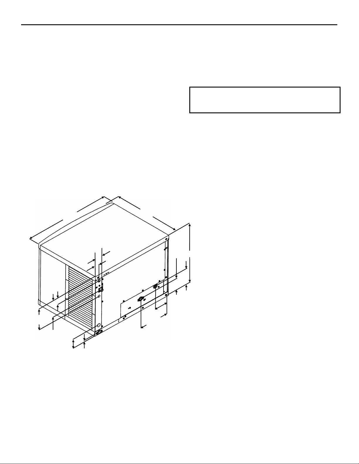
Ice Machine Dimensions
Q800 ICE MACHINE
WATER COOLED
2.38”
(6.05 cm)
7.88”
(20.02 cm)
5.75”
(14.61 cm)
(7.95 cm)
30.00”
(76.20 cm)
3.13”
0.75”
(1.91 cm)
2.50”
(6.35 cm)
1.88”
(4.78 cm)
24.50”
(62.23 cm)
10.38”
(26.37 cm)
SV1612
3.38”
(8.59 cm)
(12.70 cm)
4.38”
(11.12 cm)
Important
Failure to follow these installation guidelines may
affect warranty coverage.
H
5.00”
2-1
Page 8
Installation Instructions Section 2
Location of Ice Machine
The location selected for the ice machine must meet
the following criteria. If any of these criteria are not
met, select another location.
• The location must be free of airborne and other
contaminants.
• The air temperature must be at least 35°F (1.6°C),
but must not exceed 110°F (43.4°C).
• The location must not be near heat-generating
equipment or in direct sunlight.
• The location must not obstruct air flow through or
around the ice machine. Refer to the chart below
for clearance requirements.
Water-Cooled
Top/Sides 5” (127 mm)*
Back 5” (127 mm)*
*There is no minimum clearance required. This value
is recommended for efficient operation and servicing
only.
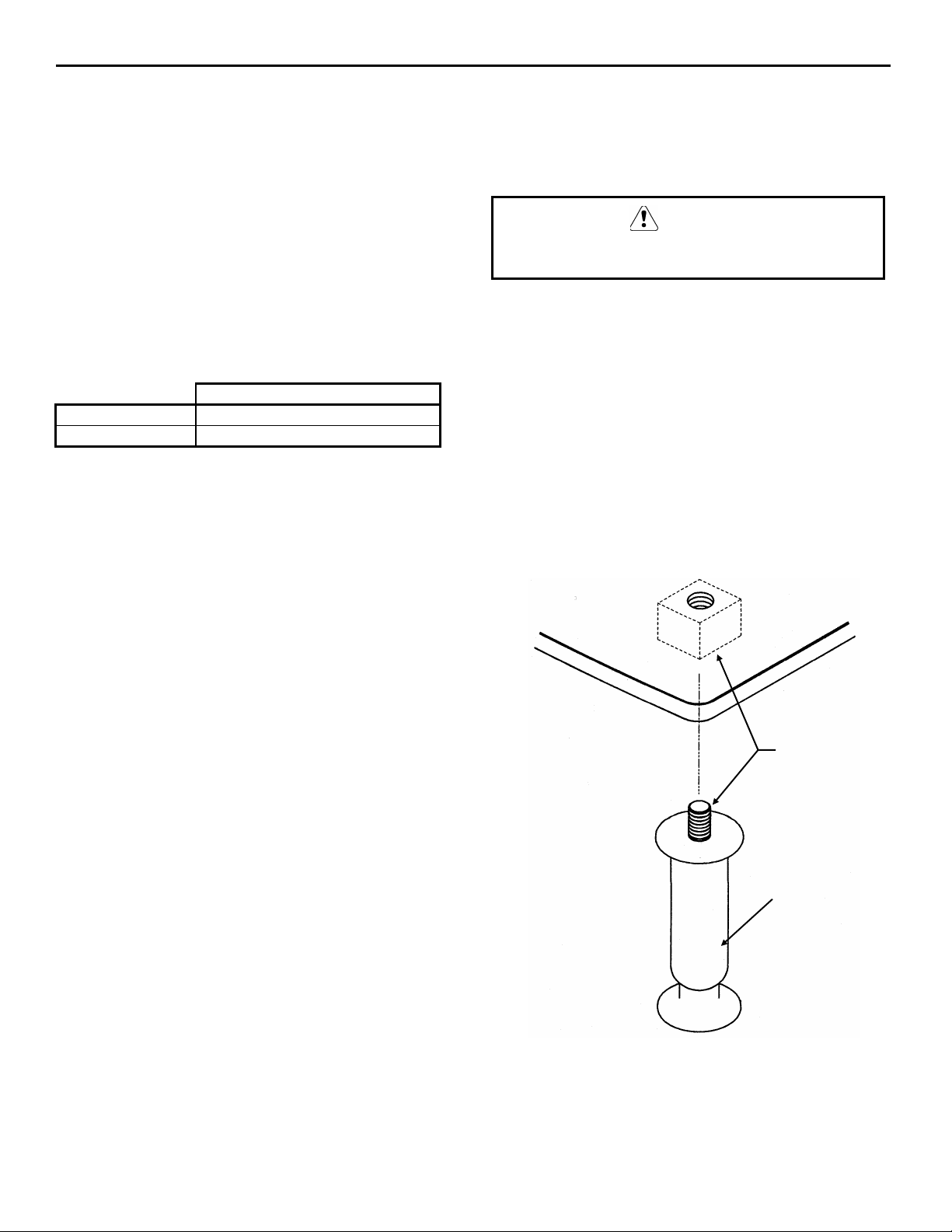
Leveling the Ice Storage Bin
1. Screw the leveling legs onto the bottom of the
bin.
2. Screw the foot of each leg in as far as possible.
CAUTION
The legs must be screwed in tightly to prevent
them from bending.
3. Move the bin into its final position.
4. Level the bin to assure that the bin door closes
and seals properly. Use a level on top of the bin.
Turn each foot as necessary to level the bin.
5. Inspect bin gasket prior to ice machine
installation. (Manitowoc bins come with a closed
cell foam gasket installed along the top surface of
the bin.)
6. Install ice machine on bin.
NOTE: An optional caster assembly is available for
use in place of the legs. Installation instructions are
supplied with the casters.
THREAD “FOOT”
Leveling Leg and Foot
THREAD
LEVELING LEG
INTO BASE OF
CABINET
IN AS FAR AS
POSSIBLE
SV1606
2-2
Page 9
Section 2 Installation Instructions
Electrical Service
GENERAL
WARNING
All wiring must conform to local, state and
national codes.
VOLTAGE
The maximum allowable voltage variation is ± 10%
of the rated voltage at ice machine start-up (when the
electrical load is highest).
The ice machine must be grounded in accordance
with national and local electrical codes.
FUSE/CIRCUIT BREAKER
A separate fuse/circuit breaker must be provided for
each ice machine. Circuit breakers must be H.A.C.R.
rated (does not apply in Canada).
MINIMUM CIRCUIT AMPACITY
The minimum circuit ampacity is used to help select
the wire size of the electrical supply. (Minimum
circuit ampacity is not the ice machine’s running amp
load.)
The wire size (or gauge) is also dependent upon
location, materials used, length of run, etc., so it must
be determined by a qualified electrician.
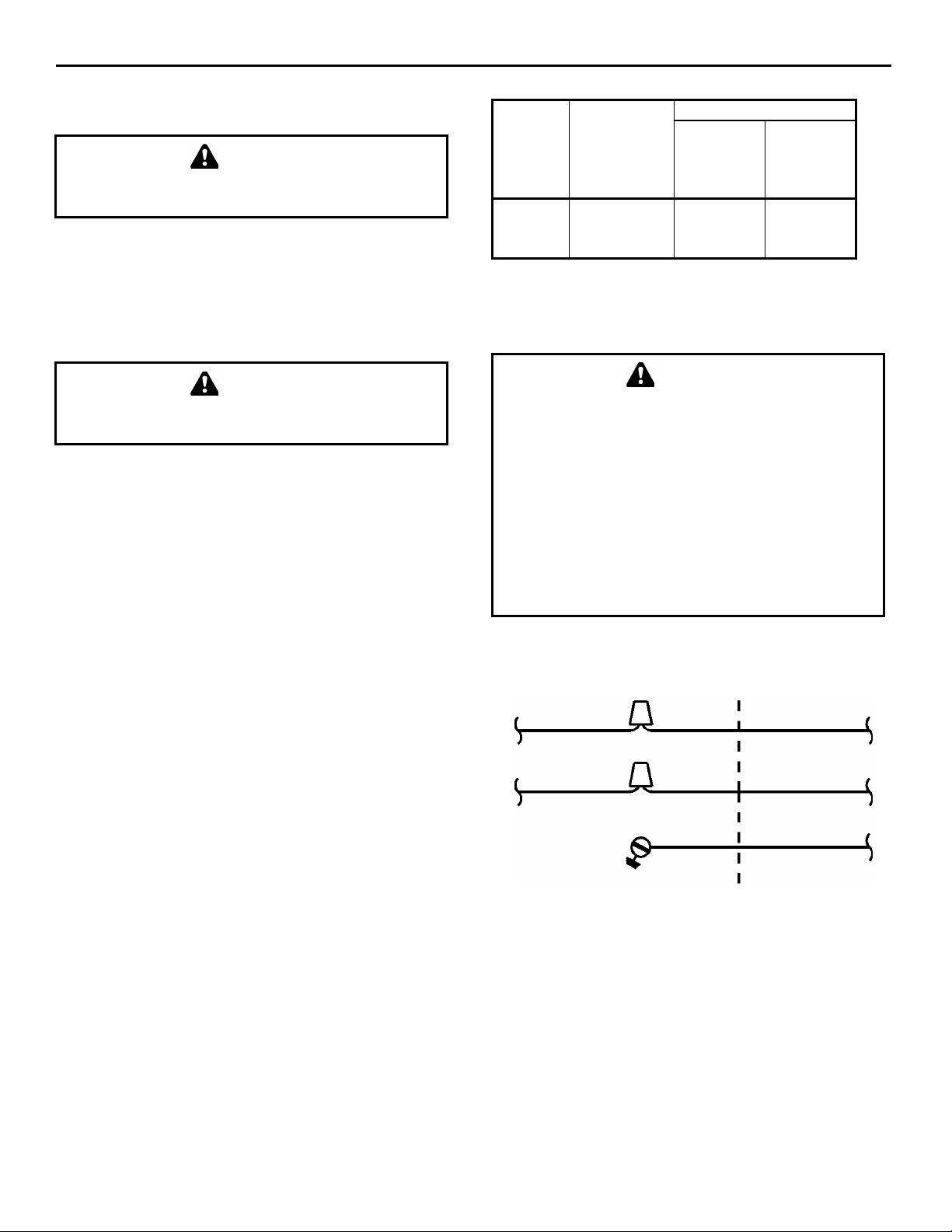
WARNING
Q800 ICE MACHINE
Voltage Water Cooled
Ice
Machine
Q800
Phase
Cycle
208-230/1/60
208-230/3/60
230/1/50
Maximum
Fuse
Circuit
Breaker
20
15
20
Minimum
Circuit
Amps
11.4
8.2
10.6
Electrical Wiring Connections
These diagrams are not intended to show proper
wire routing, wire sizing, disconnects, etc., only
the correct wire connections.
All electrical work, including wire routing and
grounding, must conform to local, state and
national electrical codes.
Though wire nuts are shown in the drawings, the
ice machine field wiring connections may use
either wire nuts or screw terminals.
Water Cooled Ice Machine
208-230/1/60
L
1
WARNING
N = 115V
OR
L2 = 208-230V
L
1
GROUND
ICE MACHINE
CONNECTIONS
TO SEPARATE
FUSE/ BREAKER
GROUND
SV1258
2-3
Page 10

Installation Instructions Section 2
Water Service/Drains
Water Inlet Lines
Follow these guidelines to install water inlet lines:
• Do not connect the ice machine to a hot water
supply. Be sure all hot water restrictors installed
for other equipment are working. (Check valves
on sink faucets, dishwashers, etc.)
• If water pressure exceeds the maximum
recommended pressure, obtain a water pressure
regulator from your Manitowoc distributor.
• Install a water shut-off valve for both the ice
making and condenser water lines.
• Insulate water inlet lines to prevent condensation.
• Use teflon tape to seal threaded fittings.
Important
Install sump trough drain plug before starting the
ice machine.
WATER SUPPLY AND DRAIN LINE SIZING/CONNECTIONS
Drain Connections
Follow these guidelines when installing drain lines to
prevent drain water from flowing back into the ice
machine and storage bin:
• Drain lines must have a 1.5 inch drop per 5 feet
of run (2.5 cm per meter), and must not create
traps.
• The floor drain must be large enough to
accommodate drainage from all drains.
• Run separate bin and ice machine drain lines.
Insulate them to prevent condensation.
• Vent the bin and ice machine drain to the
atmosphere. Do not vent the condenser drain on
water-cooled models.
Plumbing must conform to applicable
codes.
CAUTION
Location
Ice Making
Water Inlet
Ice Making
Water Drain
Condenser
Water Inlet
Condenser
Water Drain
Bin Drain
Water
Temperature
33°F (0.6°C) Min.
90°F (32.2°C)
Max.
--- ---
33°F (0.6°C) Min.
90°F (32.2°C)
Max.
--- ---
--- ---
20 psi (137.9 kPA) Min.
80 psi (551.5 kPA) Max.
20 psi (137.9 kPA) Min.
150 psi (1034.2 kPA)
Water
Pressure
Max.
Ice Machine
Fitting
3/8” Female
Pipe Thread
1/2” Female
Pipe Thread
3/8” Female Pipe Thread
1/2” Female
Pipe Thread
3/4” Female
Pipe Thread
Tubing Size Up to Ice
Machine Fitting
3/8” (9.5 mm)
minimum inside
diameter
1/2” (12.7 mm)
minimum inside
diameter
1/2” (12.7 mm)
minimum inside
diameter
3/4” (19.1 mm)
minimum inside
diameter
2-4
Page 11

Section 2 Installation Instructions
WATER SUPPLY AND DRAIN LINE SIZING ILLUSTRATION
CONDENSER WATER
INLET FITTING
1/2” F.P.T. (1.27 cm)
CONDENSER WATER
INLET TUBING
1/2” MIN. I.D. (1.27 cm)
CONDENSER WATER
DRAIN TUBING
1/2” MIN. I.D. (1.27 cm)
WATER SHUT
OFF VALVE
18.00” VENT
(45.70 cm)
(SEE BELOW)
ICE MAKING WATER
INLET FITTING
3/8” F.P.T. (0.95 cm)
CONDENSER WATER
DRAIN FITTING
1/2” F.P.T. (1.27 cm)
ICE MAKING WATER
INLET TUBING
3/8” MIN. I.D. (0.95 cm)
BIN DRAIN FITTING
3/4” F.P.T (1.91 cm)
ICE MAKING WATER
DRAIN FITTING
1/2” F.P.T. (1.27 cm)
SLOPE
BIN DRAIN TUBING
3/4” MIN. I.D. (1.91 cm)
ICE MAKING WATER
DRAIN TUBING
1/2” MIN. I.D. (1.27 cm)
VENT
OPEN, TRAPPED OR
VENTED DRAIN
Typical Water Supply Drain Installation
18.00”
(45.70 cm)
VENT
SV1626
2-5
Page 12

Installation Instructions Section 2
Installation Checklist
Is the ice machine level?
Has all of the internal packing been removed?
Have all of the electrical and water connections
been made?
Has the sump trough drain plug been installed?
Has the supply voltage been tested and checked
against the rating on the nameplate?
Is their proper clearance around the ice machine
for air circulation?
Has the ice machine been installed where
ambient temperatures will remain in the range
of 35° - 110°F (1.7° - 43.3°C)?
Has the ice machine been installed where the
incoming water temperature will remain in the
range of 33° - 90°F (0.6° - 32.2°C)?
Is there a separate drain for the water-cooled
condenser?
Before Starting the Ice Machine
All Manitowoc ice machines are factory-operated and
adjusted before shipment. Normally, new
installations do not require any adjustment.
To ensure proper operation, follow the Operational
Checks in this manual. Starting the ice machine and
completing the Operational Checks are the
responsibilities of the owner/operator.
Adjustments and maintenance procedures outlined in
this manual are not covered by the warranty.
WARNING
PERSONNEL INJURY POTENTIAL
Do not operate equipment that has been misused,
abused, neglected, damaged, or altered/modified
from that of original manufactured specifications.
Are the ice machine and bin drains vented?
Are all electrical leads free from contact with
refrigeration lines and moving equipment?
Has the owner/operator been instructed
regarding maintenance and the use of
Manitowoc Cleaner and Sanitizer?
Has the owner/operator completed the warranty
registration card?
Has the ice machine and bin been sanitized?
2-6
Page 13

Section 3 Ice Machine Operation
Section 3
Ice Machine Operation
Component Identification
HOT GAS
VALVE
WATER DUMP
VALVE
DRAIN HOSE
WATER INLET
VALVE
DISTRIBUTION
TUBE
COMPRESSOR
PROBE
EVAPORATOR
ICE THICKNESS
Component Identification
WATER
CONDENSER
CONDENSER
WATER
REGULATING VALVE
SV1604
ICE/OFF/CLEAN
SWITCH
FLOW CLAMP
USED ON
REGULAR SIZE
CUBE ONLY
WATER FLOAT
VALVE
WATER CURTAIN
WATER TROUGH
WATER PUMP
SV1605
3-1
Page 14

Ice Machine Operation Section 3
Ice Making Sequence of Operation
Initial Start-Up Or Start-Up After Automatic Shut-Off
1. Water Purge
Before the compressor starts, the water pump and
water dump solenoid are energized for 45 seconds to
purge the ice machine of old water. This ensures that
the ice-making cycle starts with fresh water.
The hot gas valve is also energized during the water
purge, although it stays on for an additional 5
seconds (50 second total on time) during the initial
refrigeration system start-up.
HARVEST SEQUENCE
5. Water Purge
The water pump continues to run, and the water
dump valve energizes for 45 seconds to purge the
water in the sump trough.
After the 45 second water purge, the water pump and
dump valve de-energize. (Refer to “Water Purge
Adjustment” for details.)
The hot gas valve also opens at the beginning of the
water purge to divert hot refrigerant gas into the
evaporator.
2. Refrigeration System Start-Up
The compressor starts after the 45-second water
purge, and remains on throughout the entire Freeze
and Harvest Sequences. The hot gas valve remains on
for 5 seconds during initial compressor start-up and
then shuts off.
At the same time the compressor starts, the condenser
fan motor (air-cooled models) is supplied with power
throughout the entire Freeze and Harvest Sequences.
The fan motor is wired through a fan cycle pressure
control, therefore it may cycle on and off. (The
compressor and condenser fan motor are wired
through the contactor. As a result, any time the
contactor coil is energized, the compressor and fan
motor are supplied with power.)
FREEZE SEQUENCE
3. Prechill
The compressor is on for 30 seconds prior to water
flow to prechill the evaporator.
4. Freeze
The water pump restarts after the 30-second prechill.
An even flow of water is directed across the
evaporator and into each cube cell, where it freezes.
The water fill valve will cycle on, then off one more
time to refill the water trough.
6. Harvest
The hot gas valve remains open and the refrigerant
gas warms the evaporator causing the cubes to slide,
as a sheet, off the evaporator and into the storage bin.
The sliding sheet of cubes swings the water curtain
out, opening the bin switch.
The momentary opening and re-closing of the bin
switch terminates the harvest sequence and returns
the ice machine to the Freeze Sequence (steps 3 - 4).
AUTOMATIC SHUT-OFF
7. Automatic Shut-Off
When the storage bin is full at the end of a harvest
sequence, the sheet of cubes fails to clear the water
curtain and will hold it open. After the water curtain
is held open for 7 seconds, the ice machine shuts off.
The ice machine remains off for 3 minutes before it
can automatically restart.
The ice machine remains off until enough ice has
been removed from the storage bin to allow the ice to
fall clear of the water curtain. As the water curtain
swings back to the operating position, the bin switch
re-closes and the ice machine restarts (steps 1 - 2),
provided the 3-minute delay period is complete.
When sufficient ice has formed, the water flow (not
the ice) contacts the ice thickness probe. After
approximately 7 seconds of continual water contact,
the harvest sequence is initiated. The ice machine
cannot initiate a harvest sequence until a 6-minute
freeze lock has been surpassed.
3-2
Page 15

Section 3 Ice Machine Operation
A
Operational Checks
GENERAL
Your Manitowoc ice machine was factory-operated
and adjusted before shipment. Normally, a newly
installed ice machine does not require any
adjustment.
To ensure proper operation, always follow these
Operational Checks when starting the ice machine:
• for the first time
• after a prolonged out of service period
• after cleaning and sanitizing
Routine adjustments and maintenance procedures
outlined in this manual are not covered by the
warranty.
WATER LEVEL CHECK
1. Check the water level while the ice machine is in
the freeze mode and the water pump is running.
The correct water level is 1/8”-1/2” (3-12.5 mm)
above the water pump impeller housing.
B. Raise or lower the float valve assembly as
necessary, then tighten the screws.
C. If further adjustment is required, carefully
bend the float arm to achieve the correct
water level.
ICE THICKNESS CHECK
After a harvest cycle, inspect the ice cubes in the ice
storage bin. The ice thickness probe is factory-set to
maintain an ice bridge of 1/8 inch (3.2mm). If an
adjustment is needed, follow the steps below.
1. Turn the ice thickness probe adjustment screw
clockwise for a thicker ice bridge, or
counterclockwise for a thinner ice bridge.
IMPORTANT
It is normal for cubes to have a slight dimple. This
is a normal characteristic associated with
Manitowoc’s unique shape.
WATER
PUMP
PUMP
OUTLET
WATER LEVEL
1/8”-1/2” ABOVE
HOUSING
Water Level Check
WATER PUMP
IMPELLER
HOUSING
SV1331
2. The float valve is factory-set for the proper water
level. If adjustments are necessary:
A. Loosen the two screws on the float valve
bracket.
DJUSTING
SCREW
1/8” ICE
THICKNESS
SV1208
Ice Thickness Adjustment
2. Make sure the ice thickness probe wire and
bracket do not restrict movement of the probe.
3-3
Page 16

Ice Machine Operation Section 3
HARVEST SEQUENCE WATER PURGE
The harvest sequence water purge adjustment may be
used when the ice machine is hooked up to special
water systems, such as a de-ionized water treatment
system.
Important
The harvest sequence water purge is factory-set at
45 seconds. A shorter purge setting is not
recommended. This can increase water system
cleaning and sanitizing requirements.
• The harvest sequence water purge may be set to
15, 30, or 45 seconds.
• During the harvest sequence water purge, the
water fill valve energizes and de-energizes by
time. The water purge must be at the factory
setting of 45 seconds for the water fill valve to
energize during the last 15 seconds of the water
purge. If it is set to less than 45 seconds, the
water fill valve will not energize during the water
purge.
WARNING
Disconnect the electrical power to the ice machine
at the electrical disconnect before proceeding.
For your safety, and to eliminate errors, we
recommend that a qualified service technician make
the harvest water purge adjustment.
CONTROL
BOARD
WATER PURGE
ADJUSTMENT
30
15
45
SV1617
Water Purge Adjustment
3-4
Page 17

Section 4 Maintenance
Section 4
Maintenance
WATER-COOLED CONDENSER
AND WATER REGULATING VALVE
The water-cooled condenser and water-regulating
valve may require cleaning due to scale build-up.
Low ice production, high water consumption and
high operating temperatures and pressures all may be
symptoms of restrictions in the condenser water
circuit.
Because the cleaning procedures require special
pumps and cleaning solutions, they must be
performed by qualified maintenance or service
personnel. Follow the manufacturer instructions for
the specific product used.
MANITOWOC’S PATENTED CLEANING OR SANITIZING TECHNOLOGY
Manitowoc ice machines include technology that
allows the initiation and completion of a cleaning or
sanitizing cycle at the flip of a switch. This cycle will
permit cleaning or sanitizing of all surfaces that come
in contact with the water distribution system.
Periodic maintenance must be performed that
includes sanitizing the bin (or dispenser) and adjacent
surface areas, which can not be contacted by the
water distribution system.
This technology will also allow initiation and
completion of a clean or sanitize cycle after which
the ice machine automatically starts ice making
again.
Refer to the cleaning or sanitizing procedure for
complete details.
4-1
Page 18

Maintenance Section 4
Interior Cleaning and Sanitizing
GENERAL
Clean and sanitize the ice machine every six months
for efficient operation. If the ice machine requires
more frequent cleaning and sanitizing, consult a
qualified service company to test the water quality
and recommend appropriate water treatment or
installation of the AuCS® accessory (Automatic
Cleaning System). If required, an extremely dirty ice
machine may be taken apart for cleaning and
sanitizing.
CAUTION
Use only Manitowoc approved Ice Machine
Cleaner (part number 94-0546-3) and Sanitizer
(part number 94-0565-3). It is a violation of Federal
law to use these solutions in a manner inconsistent
with their labeling. Read and understand all labels
printed on bottles before use.
Do not mix Ice Machine Cleaner and Sanitizer
solutions together. It is a violation of Federal law to
use these solutions in a manner inconsistent with
their labeling.
Wear rubber gloves and safety goggles (and/or face
shield) when handling Ice Machine Cleaner or
Sanitizer.
CLEANING PROCEDURE
Ice machine cleaner is used to remove lime scale or
other mineral deposits. It is not used to remove algae
or slime. Refer to “Sanitizing Procedure” on the next
page for removal of algae and slime. To initiate a
cleaning cycle using Manitowoc’s Patented Cleaning
Technology use the following procedure.
Step 1 Set the toggle switch to the OFF position
after ice falls from the evaporator at the end of a
Harvest cycle. Or, set the switch to the OFF position
and allow the ice to melt off the evaporator.
CAUTION
WARNING
CAUTION
Never use anything to force ice from the
evaporator. Damage may result.
Step 2 To start a cleaning cycle, move the toggle
switch to the CLEAN position. The water will flow
through the water dump valve and down the drain.
The Clean light will turn on to indicate the ice
machine is in the Clean mode.
Step 3 Wait about one minute or until water starts to
flow over the evaporator.
Step 4 Add the proper amount of Manitowoc Ice
Machine Cleaner to the water trough.
Model Amount of Cleaner
Q800 5 ounces (150 ml)
Step 5 The ice machine will automatically time out a
ten-minute cleaning cycle, followed by six rinse
cycles, and then stop. The Clean light will turn off to
indicate the clean mode is completed. This entire
cycle lasts approximately 25 minutes.
NOTE: Periodic cleaning must be performed on
adjacent surface areas not contacted by the water
distribution system.
Step 6 When the cleaning process stops, move the
toggle switch to the OFF position. Refer to
“Sanitizing Procedure” on the next page.
Step 7
A. The ice machine may be set to start and finish
a cleaning procedure, and then automatically
start ice making again.
B. Wait about one minute into the cleaning cycle
(until water starts to flow over the
evaporator), then move the switch from
CLEAN to ICE position.
C. When the cleaning cycle is completed, the
clean light will turn off and a ice making
sequence will start automatically.
NOTE: After the toggle switch is moved to the ICE
position, opening the curtain switch will interrupt the
cleaning sequence. The sequence will resume from
the point of interruption when the curtain switch
closes.
4-2
Page 19

Section 4 Maintenance
Sanitizing Procedure
Use sanitizer to remove algae or slime. Do not use it
to remove lime scale or other mineral deposits. To
initiate a sanitizing cycle using Manitowoc’s
Patented Cleaning/Sanitizing Technology use the
following procedure.
Step 1 Set the toggle switch to the OFF position
after ice falls from the evaporator at the end of a
Harvest cycle. Or, set the switch to the OFF position
and allow the ice to melt off the evaporator.
CAUTION
Never use anything to force ice from the
evaporator. Damage may result.
Step 6 When the sanitizing process stops, move the
toggle switch to the ICE position to start making ice
again.
Step 7
A. The ice machine may be set to start and finish
a sanitizing procedure, and then automatically
start ice making again.
B. Wait about one minute into the sanitizing
cycle (until water starts to flow over the
evaporator), then move the switch from
WASH to ICE position.
C. When the sanitizing cycle is completed, the
clean light will turn off and a ice making
sequence will start automatically.
Step 2 To start a sanitizing cycle, move the toggle
switch to the CLEAN position. The water will flow
through the water dump valve and down the drain.
The Clean light will turn on to indicate the ice
machine is in the Cleaning mode.
Step 3 Wait about one minute or until water starts to
flow over the evaporator.
Step 4 Add the proper amount of Manitowoc Ice
Machine Sanitizer to the water trough.
Model Amount of Sanitizer
Q800 3 ounces (90 ml)
Step 5 The ice machine will automatically time out a
ten-minute sanitizing cycle, followed by six rinse
cycles, and then stop. The Clean light will turn off to
indicate the sanitizing mode is completed. This
entire cycle lasts approximately 25 minutes.
Note: Periodic cleaning must be performed on
adjacent surface areas not contacted by the water
distribution system. If the bin requires sanitizing,
remove all of the ice and sanitize it with a solution of
1 ounce (30 ml) of sanitizer with up to 4 gallons
(15/l) of water.
NOTE: After the toggle switch is moved to the ICE
position, opening the curtain switch will interrupt the
sanitizing sequence. The sequence will resume from
the point of interruption when the curtain switch
closes.
4-3
Page 20

Maintenance Section 4
REMOVAL OF PARTS FOR
CLEANING OR SANITIZING
1. Turn off the water supply to the ice machine at
the water service valve.
WARNING
Disconnect electric power to the ice machine at the
electric switch box before proceeding.
2. Remove the parts of the water curtain and the
components you want to clean or sanitize. See the
following pages for removal procedures for these
parts.
WARNING
Wear rubber gloves and safety goggles (and/or face
shield) when handling Ice Machine Cleaner or
Sanitizer.
1. Soak the removed part(s) in a properly mixed
solution.
Solution Type Water Mixed With
Cleaner 1 gal. (4 l) 16 oz (500 ml) cleaner
Sanitizer 4 gal. (15 l) 1 oz (30 ml) sanitizer
4. Use a soft-bristle brush or sponge (NOT a wire
brush) to carefully clean the parts.
CAUTION
Do not mix Cleaner and Sanitizer solutions
together. It is a violation of Federal law to use these
solutions in a manner inconsistent with their
labeling.
CAUTION
Do not immerse the water pump motor in the
cleaning or sanitizing solution.
5. Use the solution and a brush to clean the top,
sides, and bottom evaporator extrusions; the
inside of the ice machine panels; and the entire
inside of the bin.
6. Thoroughly rinse all of the parts and surfaces
with clean water.
7. Install the removed parts.
NOTE: Incomplete rinsing of the ice thickness probe
or water level probe may leave a residue. This could
cause the ice machine to malfunction. For best
results, brush or wipe the probes off while rinsing it.
Thoroughly dry the probes before installing them.
8. Turn on the water and electrical supply.
4-4
Page 21

Section 4 Maintenance
Water Dump Valve
The water dump valve normally does not require
removal for cleaning. To determine if removal is
necessary:
1. Locate the water dump valve.
2. Set the toggle switch to ICE.
3. While the ice machine is in the freeze mode,
check the dump valve’s clear plastic outlet drain
hose for leakage.
A. If the dump valve is leaking, remove,
disassemble and clean it.
B. If the dump valve is not leaking, do not
remove it. Instead, follow the “Cleaning
Procedure” on page 4-3.
Follow the procedure below to remove the dump
valve.
WARNING
Disconnect the electric power to the ice machine at
the electric service switch box and turn off the
water supply before proceeding.
1. If so equipped, remove the water dump valve
shield from its mounting bracket.
2. Lift and slide the coil retainer cap from the top of
the coil.
3. Note the position of the coil assembly on the
valve for assembly later. Leaving the wires
attached, lift the coil assembly off the valve body
and the enclosing tube.
4. Press down on the plastic nut on the enclosing
tube and rotate it 1/4 turn. Remove the enclosing
tube, plunger, and plastic gasket from the valve
body.
NOTE: At this point, the water dump valve can easily
be cleaned. If complete removal is desired, continue
with step 5.
3. RETAI
DRAIN
HOSE
VALVE
SHIELD
WATER
DUMP
VALVE
NING
COIL
DO NOT
DISCONNECT
WIRES AT COIL
Dump Valve Removal
Important
The plunger and the inside of the enclosing tube
must be completely dry before assembly.
NOTE: During cleaning, do not stretch, damage or
remove the spring from the plunger. If it is removed,
slide the spring’s flared end into the plunger’s slotted
top opening until the spring contacts the plunger
spring stop.
5. Remove the valve body.
6. Remove the tubing from the dump valve by
twisting the clamps off.
7. Remove the two screws securing the dump valve
and the mounting bracket.
P
CAP
PLUNGER
SPRING STO
Dump Valve Disassembly
COIL
SPRING
PLUNGER
ENCLOSING
TUBE
3. DIAPH
RAM
VALVE BODY
Dump Valve Disassembly
4-5
Page 22

Maintenance Section 4
Water Pump
WARNING
Disconnect the electric power to the ice machine at
the electric service switch box and turn off the
water supply.
1. Disconnect the water pump power cord.
WATER
PUMP
POWER
CORD
LOOSEN
SCREWS
PUMP
OUTLET
Ice Thickness Probe
1. Compress the side of the ice thickness probe near
the top hinge pin and remove it from the bracket.
DISCONNECT
WIRE LEAD
COMPRESS
HINGE PIN
TO REMOVE
ICE
THICKNESS
PROBE
SV1619
Ice Thickness Probe Removal
SV1618
Water Pump Removal
2. Disconnect the hose from the pump outlet.
3. Loosen the screws securing the pump mounting
bracket to the bulkhead.
4. Lift the pump and bracket assembly off the
screws.
NOTE: At this point, the ice thickness probe can
easily be cleaned. If complete removal is desired,
continue with step 2 below.
WARNING
Disconnect the electric power to the ice machine at
the electric service switch box.
2. Disconnect the wire lead from the control board
inside the electrical control box.
4-6
Page 23

Section 4 Maintenance
Float Valve
1. Turn off the water supply to the ice machine at
the water service valve.
2. Turn the splash shield counterclockwise one or
two turns.
WATER INLET
COMPRESSION
FITTING
FILTER SCREEN
AND CAP
TUBE
SPLASH
SHIELD
Float Valve Removal
SV1217
3. Pull the float valve forward and off the mounting
bracket.
4. Disconnect the water inlet tube from the float
valve at the compression fitting.
5. Remove the filter screen and cap for cleaning.
4-7
Page 24

Maintenance Section 4
Water Distribution Tube
1. Disconnect the water hose from the distribution
tube.
DISTRIBUTION
TUBE
THUMBSCREW
1. LIFT UP
2. SLIDE BACK
3. SLIDE TO RIGHT
3
2
1
THUMBSCREW
LOCATING PIN
SV1620
Water Distribution Tube Removal
1. Loosen the two thumbscrews, which secure the
distribution tube.
2. Lift the right side of the distribution tube up off
the locating pin, then slide it back and to the
right.
Water Curtain
1. Gently flex the curtain in the center and remove it
from the right side.
STEP 1
STEP 2
SV1213
Water Curtain Removal
2. Slide the left pin out.
CAUTION
Do not force this removal. Be sure the locating pin
is clear of the hole before sliding the distribution
tube out.
3. Disassemble for cleaning.
A. Twist both of the inner tube ends until the
tabs line up with the keyways.
B. Pull the inner tube ends outward.
KEYWAY
INNER
TUBE
TAB
SV1211
INNER
TUBE
4-8
Water Distribution Tube Disassembly
Page 25

Section 5 Before Calling for Service
Section 5
Before Calling for Service
Checklist
If a problem arises during operation of your ice machine, follow the checklist below before calling for service.
Routine adjustments and maintenance procedures are not covered by the warranty.
Problem Possible Cause To Correct
Ice machine does not operate. No electrical power to the ice
machine.
ICE/OFF/CLEAN toggle switch set
improperly.
Water curtain stuck open. Water curtain must be installed and
Ice machine stops, and can be
restarted by moving the toggles
switch to OFF and back to ICE.
Ice machine does not release
ice or is slow to harvest.
Ice machine is not level. Level the ice machine.
Water regulating valve leaks in harvest
Ice machine does not cycle
into harvest mode.
Ice thickness probe is dirty. Clean and sanitize the ice machine.
Ice thickness probe wire is
Ice thickness probe is out of
Uneven ice fill (thin at top of
Ice quality is poor (soft or not
clear).
Water filtration is poor. Replace the filter.
Ice machine is dirty. Clean and sanitize the ice machine.
Water dump valve is not working. Disassemble and clean the water
Safety limit feature stopping the ice
machine.
Ice machine is dirty. Clean and sanitize the ice machine.
mode (water-cooled models).
The six-minute freeze time lock-in has
not expired yet.
disconnected.
adjustment.
evaporator).
Poor incoming water quality. Contact a qualified service company
Replace the fuse/reset the
breaker/turn on the main switch.
Move the toggle switch to the ICE
position.
swinging freely.
Refer to “Safety Limit Feature” on the
next page.
.
Adjust or Replace Water-regulating
valve.
Wait for freeze lock-in to expire.
Connect the wire.
Adjust the ice thickness probe.
See “Shallow or Incomplete Cubes”
on the next page.
to test the quality of the incoming
water and make appropriate filter
recommendations.
dump valve.
Continued on next page...
5-1
Page 26

Before Calling for Service Section 5
Problem Possible Cause To Correct
Ice machine produces shallow
or incomplete cubes, or the ice
fill pattern on the evaporator is
incomplete.
Water float valve filter screen is dirty. Remove the water float valve and
Water filtration is poor. Replace the filter.
Hot incoming water. Connect the ice machine to a cold
Water float valve is not working. Remove the water float valve and
Incorrect incoming water pressure. Water pressure must be 20-80 psi
Ice machine is not level. Level the ice machine.
Low ice capacity. Water float valve filter screen is dirty. Remove the water float valve and
Incoming water supply is shut off. Open the water service valve.
Water float valve stuck open or
Safety Limit Feature
In addition to the standard safety controls, such as
the high pressure cutout, your Manitowoc ice
machine features built-in safety limits which will
stop the ice machine if conditions arise which could
cause a major component failure.
Before calling for service, re-start the ice machine
using the following procedure:
Ice thickness probe is out of
adjustment.
Water tro ugh level i s to high or too low. Set water level.
leaking.
Adjust the ice thickness probe.
clean the filter screen.
water supply
clean it.
(137.9 - 551.5 kPA).
clean the filter screen.
Remove the water float valve and
clean it.
1. Move the ICE/OFF/CLEAN switch to OFF and
then back to ICE.
A. If the safety limit feature has stopped the ice
machine, it will restart after a short delay.
Proceed to step 2.
B. If the ice machine does not restart, see “Ice
machine does not operate” on the previous
page.
2. Allow the ice machine to run to determine if the
condition is recurring.
A. If the ice machine stops again, the condition
has recurred. Call for service.
B. If the ice machine continues to run, the
condition has corrected itself. Allow the ice
machine to continue running.
5-2
Page 27

Page 28

We reserve the right to make product
improvements at any time.
Specifications and design are subject
to change without notice.
MANITOWOC ICE, INC.
2110 South 26th Street P.O. Box 1720
Manitowoc, WI 54221-1720
Web Site - www.manitowocice.com
Phone: (920) 682-0161
Fax: (920) 683-7585
©2000 Manitowoc Ice, Inc.
Litho in U.S.A.
 Loading...