

Page 1
P Model
Point of Use
Ice
Machine
Installation,
Use and Care,
and Service Manual
Thank you for selecting a Manitowoc Ice Machine, the dependability leader in ice making equipment and
related products. With proper care and maintenance, your new Manitowoc Ice Machine will provide you
with many years of reliable and economical performance.
Page 2

Part Number 80-1125-3
Page 3
Safety Notices
Procedural Notices
When using or servicing a P Model Ice Machine, be
sure to pay close attention to the safety notices in
this manual. Disregarding the notices may lead to
serious injury and/or damage to the ice machine.
Throughout this manual, you will see the following
types of safety notices:
WARNING
Text in a Warning box alerts you to a potential
personal injury situation. Be sure to read the
Warning statement, and then proceed carefully.
CAUTION
Text in a Caution box alerts you to a situation in
which you could damage the ice machine. Be sure
to read the Caution statement, and then proceed
carefully.
When using or servicing a P Model Ice Machine, be
sure to read the procedural notices in this manual.
These notices supply helpful and important
information.
Throughout this manual, you will see the following
types of procedural notices:
Important
Important boxes serve two functions.
They call the operator’s attention to important
information.
They also provide the service technician with
information that may help in performing a
procedure more efficiently. Disregarding this
information may slow down the work.
NOTE: Text set off as a Note provides you with
simple, but useful, extra information.
CAUTION
Proper care and maintenance are essential for
trouble-free operation of your Manitowoc Ice
Machine.
Read and understand this manual. It contains
valuable care and maintenance information. If you
encounter problems not covered by this manual,
feel free to contact Manitowoc Ice, Inc. We will be
happy to provide assistance.
Page 4

Page 5

We reserve the right to make product
improvements at any time.
MANITOWOC ICE, INC.
2110 South 26th Street P.O. Box 1720
Manitowoc, WI 54221-1720
Phone: (920) 682-0161
Service Fax: (920) 683-7585
Web Site: http://www.manitowocice.com
Specifications and design are subject to
change without notice.
ã1998 Manitowoc Ice, Inc.
Litho in USA
Page 6

Table of Contents
Table of Contents
Section 1 - General Information
Model Numbers................................................................................................................................................1-1
Accessories ........................................................................................................................................................1-1
Model/Serial Number Location.......................................................................................................................1-2
Owner Warranty Registration Card..............................................................................................................1-3
Warranty Coverage..........................................................................................................................................1-3
Section 2 - Installation Instructions
General..............................................................................................................................................................2-1
Ice Machine Dimensions..................................................................................................................................2-1
Location of Ice Machine ..................................................................................................................................2-2
Location of Condensing Unit...........................................................................................................................2-2
Leveling the Ice Machine.................................................................................................................................2-2
Electrical Service..............................................................................................................................................2-3
Water Service/Drains.......................................................................................................................................2-4
Refrigerant Charge..........................................................................................................................................2-5
Pre-Charged Lineset Installation
Routing Pre-Charged Linesets..................................................................................................................2-7
Lengthening or Reducing Line Set Lengths ............................................................................................2-8
Connecting a Lineset..................................................................................................................................2-9
Lineset Service Valves................................................................................................................................2-9
Installation Checklist.......................................................................................................................................2-10
Before Starting the Ice Machine.....................................................................................................................2-10
Section 3 - Ice Machine Operation
Component Identification................................................................................................................................3-1
Ice Making Sequence of Operation ................................................................................................................3-2
Operational Checks..........................................................................................................................................3-4
Section 4 - Maintenance
General..............................................................................................................................................................4-1
Ice Machine Inspection....................................................................................................................................4-1
Exterior Cleaning.............................................................................................................................................4-1
Cleaning the Condenser...................................................................................................................................4-1
Interior Cleaning and Sanitizing ....................................................................................................................4-2
Removal of Parts for Cleaning/Sanitizing......................................................................................................4-4
Water Treatment/Filtration............................................................................................................................4-9
Removal from Service/Winterization.............................................................................................................4-10
i
Page 7

Table of Contents
Table of Contents (co n t . )
Section 5 - Before Calling for Service
Checklist............................................................................................................................................................5-1
Safety Limit Stand-By Mode...........................................................................................................................5-2
Section 6 – Service
Energized Parts Chart.....................................................................................................................................6-1
Main Fuse..........................................................................................................................................................6-2
Bin Switch.........................................................................................................................................................6-2
Toggle Switch....................................................................................................................................................6-4
Harvest Heater Element ..................................................................................................................................6-4
Harvest Heater Element Thermostat .............................................................................................................6-5
Low Pressure Control......................................................................................................................................6-5
Suction Solenoid valve .....................................................................................................................................6-6
Line Set Isolation valves ..................................................................................................................................6-6
Evaporator removal.........................................................................................................................................6-7
Control Board...................................................................................................................................................6-8
Safety Limits.....................................................................................................................................................6-9
Ice Thickness Probe (Harvest Initiation)
How the Probe Works................................................................................................................................6-12
Harvest/Safety Limit Light........................................................................................................................6-12
Freeze Time Lock-In Feature....................................................................................................................6-12
Maximum Freeze Time..............................................................................................................................6-12
Ice Thickness Check...................................................................................................................................6-12
Diagnosing Ice Thickness Control Circuitry
Ice Machine Does Not Cycle Into Harvest ........................................................................................6-13
Ice Machine Prematurely Cycles Into Harvest .................................................................................6-14
Water Level Control Circuitry
Water Level Probe Light...........................................................................................................................6-15
Freeze Cycle Water Level Setting.............................................................................................................6-15
Water Inlet Valve Safety Shut-off ............................................................................................................6-15
Freeze Cycle Circuitry...............................................................................................................................6-15
Harvest Cycle Circuitry.............................................................................................................................6-15
Diagnosing Freeze Cycle Potable Water Circuitry
Water Trough Overfilling During The Freeze Cycle........................................................................6-16
Water Will Not Run Into The Sump Trough During The Freeze Cycle.........................................6-18
Wiring Diagram................................................................................................................................................6-19
Tubing Schematic.............................................................................................................................................6-20
24 Hour Production Graphs
P520/P530....................................................................................................................................................6-21
ii
Page 8

Section 1 General Information
Section 1
General Information
Model Numbers
This manual covers the following models:
Ice Machine
PD0522N
PY0524N
PD0532N
PY0534N
Accessories
Contact your Manitowoc distributor for these
optional accessories:
BIN CASTER
Replaces standard legs.
ICE BAGGER
Maximize profits from bagged ice sales with this
convenient accessory. This sturdy unit rests on the
bin door frame, and adapts for left or right side
filling.
TRI-LIMINATOR WATER FILTER SYSTEM
Engineered specifically for Manitowoc ice machines,
Tri-Liminator water filters are an efficient,
dependable, and affordable method of inhibiting scale
formation, filtering sediment, and removing chlorine
taste and odor.
MANITOWOC CLEANER AND SANITIZER
Manitowoc Ice Machine Cleaner and Sanitizer are
available in convenient 16 oz. (473 ml) bottles. These
are the only cleaner and sanitizer approved for use
with Manitowoc products.
DISPENSER
A counter-top dispenser is ideal for cafeterias and
many types of self-service facilities. Manitowoc autofill, floor-standing ice dispensers meet the strict
sanitary requirements of the food service, lodging,
and health care industries.
1-1
Page 9
General Information
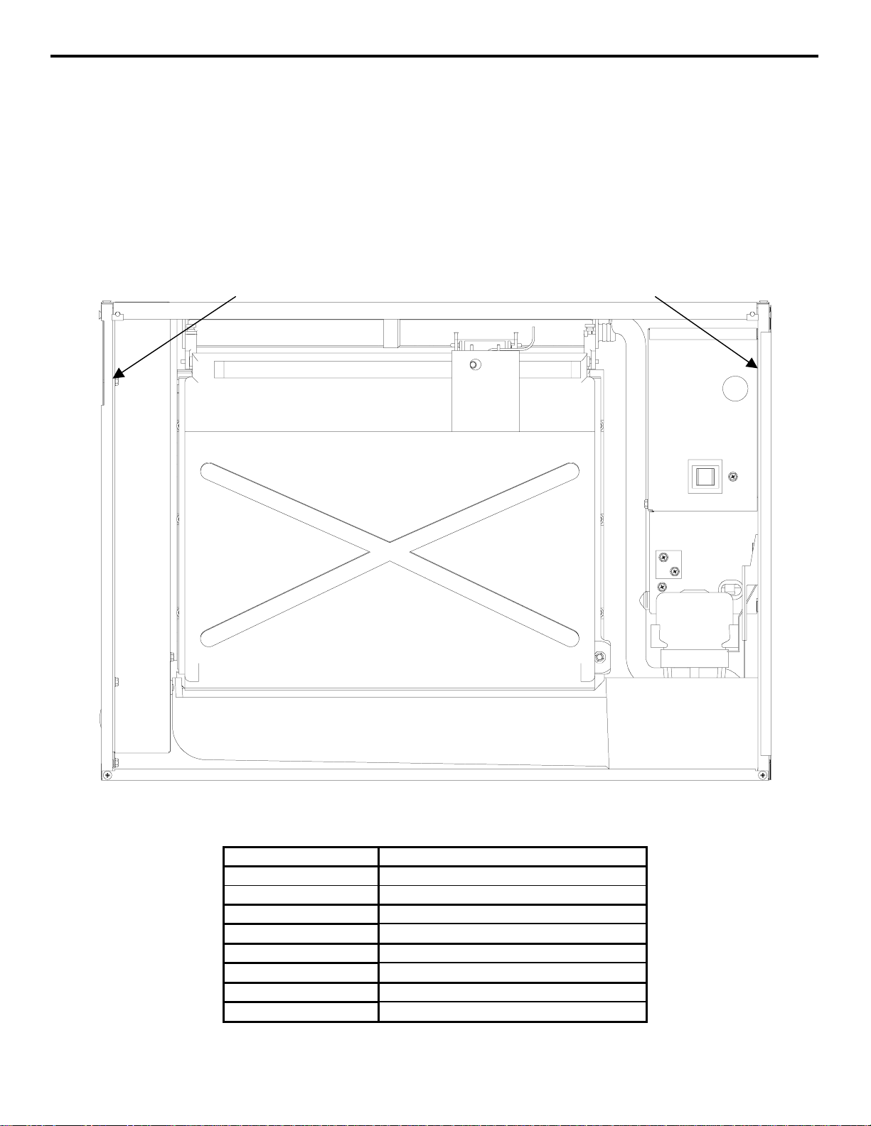
Model/Serial Number Location
Section 1
Record the model and serial number of your ice
machine and bin or dispenser in the space provided
below. These numbers are required when requesting
information from your local Manitowoc distributor,
service representative, or Manitowoc Ice, Inc.
P-520
MODEL/SERIAL
NUMBER
DECAL
The model and serial number are listed on the
OWNER WARRANTY REGISTRATION CARD.
They are also listed on the MODEL/SERIAL
NUMBER DECAL affixed to the ice machine.
P-530
MODEL/SERIAL
NUMBER
DECAL
1-2
Model/Serial Number Location
Ice Machine
Model Number
Serial Number
Model Number
Serial Number
Model Number
Serial Number
Model Number
Serial Number
SV1700A
Page 10

Section 1 General Information
Owner Warranty Registration Card
GENERAL
The packet containing this manual also includes
warranty information. Warranty coverage begins the
day your new ice machine is installed.
Important
Complete and mail the OWNER WARRANTY
REGISTRATION CARD as soon as possible to
validate the installation date.
If you do not return your OWNER WARRANTY
REGISTRATION CARD, Manitowoc will use the
date of sale to the Manitowoc Distributor as the first
day of warranty coverage for your new ice machine.
Warranty Coverage
GENERAL
The following Warranty outline is provided for your
convenience. For a detailed explanation, read the
warranty bond shipped with each product.
Contact your local Manitowoc representative or
Manitowoc Ice, Inc. if you need further warranty
information.
Important
This product is intended exclusively for
commercial application. No warranty is extended
for personal, family, or household purposes.
ICE MACHINE PARTS
1. Manitowoc warrants the ice machine against
defects in materials and workmanship, under
normal use and service for three (3) years from
the date of original installation.
2. The evaporator is covered by an additional two
(2) year (five years total) warranty beginning on
the date of the original installation.
ICE MACHINE LABOR
1. Labor required to repair or replace defective
components is covered for three (3) years from
the date of original installation.
2. The evaporator is covered by an additional two
(2) year (five years total) labor warranty
beginning on the date of the original installation.
CONDENSING UNIT WARRANTY
Condensing units (compressor ect.) are not covered
under Manitowoc’s warranty. Process all claims
following the condenser manufactures guidelines.
EXCLUSIONS
The following items are not included in the ice
machine’s warranty coverage:
1. Condensing unit parts (compressor ect) or repairs.
Contact the condensing unit manufacturer for
warranty information.
2. Normal maintenance, adjustments and cleaning as
outlined in this manual.
3. Repairs due to unauthorized modifications to the
ice machine or use of non-standard parts without
prior written approval from Manitowoc Ice, Inc.
4. Damage caused by improper installation of the
ice machine, electrical supply, water supply or
drainage, or damage caused by floods, storms, or
other acts of God.
5. Premium labor rates due to holidays, overtime,
etc.; travel time; flat rate service call charges;
mileage and miscellaneous tools and material
charges not listed on the payment schedule.
Additional labor charges resulting from the
inaccessibility of equipment are also excluded.
6. Parts or assemblies subjected to misuse, abuse,
neglect or accidents.
7. Damage or problems caused by installation,
cleaning and/or maintenance procedures
inconsistent with the technical instructions
provided in this manual.
8. This product is intended exclusively for
commercial application. No warranty is extended
for personal, family, or household purposes.
AUTHORIZED WARRANTY SERVICE
To comply with the provisions of the warranty, a
refrigeration service company, qualified and
authorized by your Manitowoc distributor, or a
Contracted Service Representative must perform the
warranty repair.
NOTE: If the dealer you purchased the ice machine
from is not authorized to perform warranty service,
contact your Manitowoc distributor or Manitowoc
Ice, Inc. for the name of the nearest authorized
service representative.
Service Calls
Normal maintenance, adjustments and cleaning as
outlined in this manual are not covered by the
warranty. If you have followed the procedures listed
on page 5-1 of this manual, and the ice machine still
does not perform properly, call your authorized
service company.
1-3
Page 11

General Information Section 1
THIS PAGE INTENTIONALLY LEFT BLANK
1-4
Page 12
Section 2 Installation Instructions
″″″″
″″″″
″″″″
″″″″
″″″″
″″″″
″″″″
″″″″
″″″″
″″″″
″″″″
″″″″
″″″″
″″″″
″″″″
″″″″
″″″″
″″″″
″″″″
″″″″
″″″″
S
9A
SV1697A
Section 2
Installation Instructions
General
These instructions are provided to assist the qualified
installer. Check your local Yellow Pages for the
name of the nearest Manitowoc distributor, or call
Failure to follow these installation guidelines may
affect warranty coverage.
Important
Manitowoc Ice, Inc. for information regarding startup services.
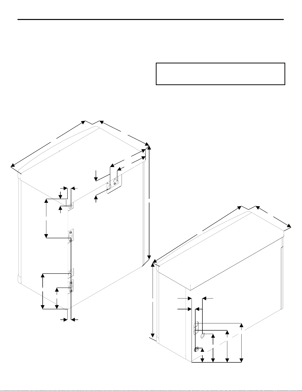
Ice Machine Dimensions
P-520 ICE MACHINE P-530 ICE MACHINE
14.75
22.00
9.65
7.50
1.39
3.12
26.50
8.12
9.34
5.00
2.31
1.25
V171
21.75
12.87
30.00
4.00
1.80
9.43
7.62
5.31
2.62
2-1
Page 13
Installation Instructions Section 2
Location of Ice Machine
The location selected for the ice machine must meet
the following criteria. If any of these criteria are not
met, select another location.
• The location must be free of airborne and other
contaminants.
• The air temperature must be at least 35°F (1.6°C),
but must not exceed 110°F (43.4°C).
• The location must not be near heat-generating
equipment or in direct sunlight.
Ice Machine
Head Section
Top/Sides 5” (127 mm)*
Back 5” (127 mm)*
There is no minimum clearance required. This value is
recommended for servicing only.
CAUTION
The ice machine must be protected if it will be
subjected to temperatures below 32°F (0°C).
Failures caused by exposure to freezing
temperatures are not covered by the warranty. See
“Removal from Service/Winterization” on page 4-
10.
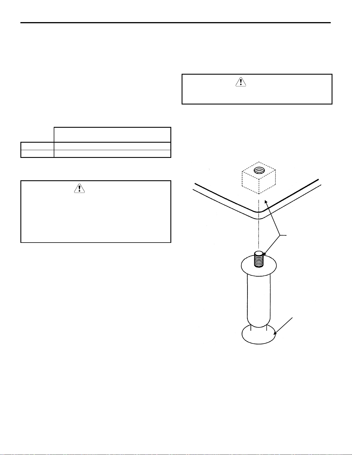
Leveling the Ice Machine
1. Screw the leveling legs onto the bottom of the
bin.
2. Screw the foot of each leg in as far as possible.
CAUTION
The legs must be screwed in tightly to prevent them
from bending.
3. Move the bin into its final position.
4. Level the bin to assure that the bin door closes
and seals properly. Use a level on top of the bin.
Turn each foot as necessary to level the bin.
THREAD
LEVELING LEG
INTO BASE OF
CABINET
Location of Condensing Unit
The location selected for the condensing unit must
meet the following criteria. If any of these criteria are
not met, select another location.
• The location must allow connection of all pre-
charged line sets, with out exceeding total
distance, rise or drop guidelines. (see page 2-7)
• Refer to the manual supplied with the condensing
unit, for Copeland’s clearance requirements.
THREAD “FOOT”
Leveling Leg and Foot
IN AS FAR AS
POSSIBLE
SV1606
2-2
Page 14
Section 2 Installation Instructions
Electrical Service
GENERAL
WARNING
All wiring must conform to local, state and national
codes.
VOLTAGE
The maximum allowable voltage variation is ± 10%
of the rated voltage at compressor start-up (when the
electrical load is highest).
WARNING
The ice machine must be grounded in accordance
with national and local electrical codes.
P-520 - P-530 - ICE MACHINES
FUSE/CIRCUIT BREAKER
A separate fuse/circuit breaker must be provided for
each ice machine. Circuit breakers must be H.A.C.R.
rated (does not apply in Canada).
MINIMUM CIRCUIT AMPACITY
The minimum circuit ampacity is used to help select
the wire size of the electrical supply. (Minimum
circuit ampacity is not the ice machine’s running amp
load).
The wire size (or gauge) is also dependent upon
location, materials used, length of run, etc., so it must
be determined by a qualified electrician.
Ice Machine
P-520 and P-530 115/1/60 20 16
CONDENSING UNIT
Refer to nameplate for correct voltage and
amperage ratings.
Scroll compressors will compress in one direction
of rotation only. Three phase compressor motors are
capable of running in either direction. Interchanging
any two of the three main power leads will reverse
the direction of rotation.
Verifying 3 Phase Direction of Rotation
Complete the entire installation of the ice machines
and condensing unit. Energize one ice machine and
the condensing unit, and monitor the suction and
discharge pressures.
Voltage/Phase/Cycle
Maximum Fuse/Circuit Breaker Minimum Circuit Amps
Symptoms of incorrect 3 phase rotation:
1. Noisy compressor operation.
2. Low amp draw
3. Elevated suction pressure.
4. Decreased head pressure
CAUTION
Verify correct compressor rotation on
three phase units.
2-3
Page 15

Installation Instructions Section 2
Water Service/Drains
WATER SUPPLY
Local water conditions may require treatment of the
water to inhibit scale formation, filter sediment, and
remove chlorine odor and taste.
Important
If you are installing a Manitowoc Tri-Liminator
water filter system, refer to the Installation
Instructions supplied with the filter system for ice
making water inlet connections.
WATER INLET LINES
Follow these guidelines to install water inlet lines:
• Do not connect the ice machine to a hot water
supply. Be sure all hot water restrictors installed
for other equipment are working. (Check valves
on sink faucets, dishwashers, etc.)
• If water pressure exceeds the maximum
recommended pressure, obtain a water pressure
regulator from your Manitowoc distributor.
• Install a water shut-off valve for the ice making
water line.
• Insulate water inlet lines to prevent condensation.
DRAIN CONNECTIONS
Follow these guidelines when installing drain lines to
prevent drain water from flowing back into the ice
machine and storage bin:
• Drain lines must have a 1.5-inch drop per 5 feet
of run (2.5 cm per meter), and must not create
traps.
• The floor drain must be large enough to
accommodate drainage from all drains.
• Run separate bin and ice machine drain lines.
Insulate them to prevent condensation.
• Vent the bin and ice machine drain to the
atmosphere.
2-4
Page 16
Section 2 Installation Instructions
WATER SUPPLY AND DRAIN LINE SIZING/CONNECTIONS
CAUTION
Plumbing must conform to state and local codes.
Location
Ice Making
Water Inlet
Ice Making
Water Drain
Bin Drain
Water
Temperature
33°F (0.6°C) Min.
90°F (32.2°C) Max.
--- ---
--- ---
Water
Pressure
20 psi (137.9 kPA) Min.
80 psi (551.5 kPA) Max.
Ice Machine
Fitting
3/8” Female Pipe
Thread
1/2” Female Pipe
Thread
3/4” Female Pipe
Thread
Tubing Size Up to Ice
Machine Fitting
3/8” (9.5 mm)
minimum inside
diameter
1/2” (12.7 mm)
minimum inside
diameter
3/4” (19.1 mm)
minimum inside
diameter
2-5
Page 17

Installation Instructions Section 2
REFRIGERANT CHARGE
The Copeland condensing unit ships from the
factory with a refrigerant charge appropriate for
installation with three ice machines, and line sets of
up to 50' (15.25 m) per ice machine.
The model/serial nameplate on the ice machine
indicates the refrigerant type.
Additional refrigerant is required for installations
using four ice machines.
The receiver is designed to hold a charge sufficient
to operate the ice machine in ambient temperatures
between -20°F (-28.9°C) and 120°F (54.4°C), with
line set lengths of up to 50' per ice machine.
CAUTION
Do not operate condensing unit without
first connecting tubing and Ice Machines
to all aeroquip fittings. The diaphragm on
the aeroquip fitting is not designed for
extended use at high system pressures,
and could result in a refrigerant Leak.
FOUR ICE MACHINE INSTALLATIONS
When connecting a fourth ice machine:
• Refrigeration systems and compressors with
POE oil must not be left open to the atmosphere
for more than 15 minutes. Open system just
prior to brazing and be prepared to hook up a
vacuum pump immediately after brazing.
• Recover the refrigerant charge in the condensing
unit.
• Braze tubing for the additional ice machine to
the manifold assembly.
• Replace the condensing unit line drier.
• Perform a leak test, evacuate system to 250
microns, and weigh in the correct refrigerant
charge.
Model Total refrigerant amount
(R-404A) as shipped from
factory.
Additional Refrigerant to be
added for fourth ice machine
Maxi mum system charge
(Never exceed)
P520/530
3 Ice Machines and 20' to
16.5 lbs. (264 oz.) None 16.5 lbs. (264 oz.)
50' of tubing per ice
machine
P520/P530
4 Ice Machines and 20' to
16.5 lbs. (264 oz.) 3.0 lbs. (48 oz.) 19.5 lbs. (312 oz.)
50' of tubing per ice
machine
When utilized with Copeland condensing unit VJAL-022Z-CFV-051 or VJAL-022Z-TFC-051
2-6
Page 18
Section 2 Installation Instructions
Line Set Installation
Ice
Machine
P520 and
P530
*Line Set Suction Line Liquid Line
Line Set*
PT-20-R404A
PT-35-R404A
PT-50-R404A
Maximum line set distance is 50′ per ice machine.
Maximum line set rise is 35′ per ice machine.
Maximum line set drop is 35′ per ice machine.
Any line set routed below the condensing unit is
considered drop.
Any line set routed above the condensing unit is
considered rise.
PT 1/2” (12.7 mm) 1/4” (6.4 mm)
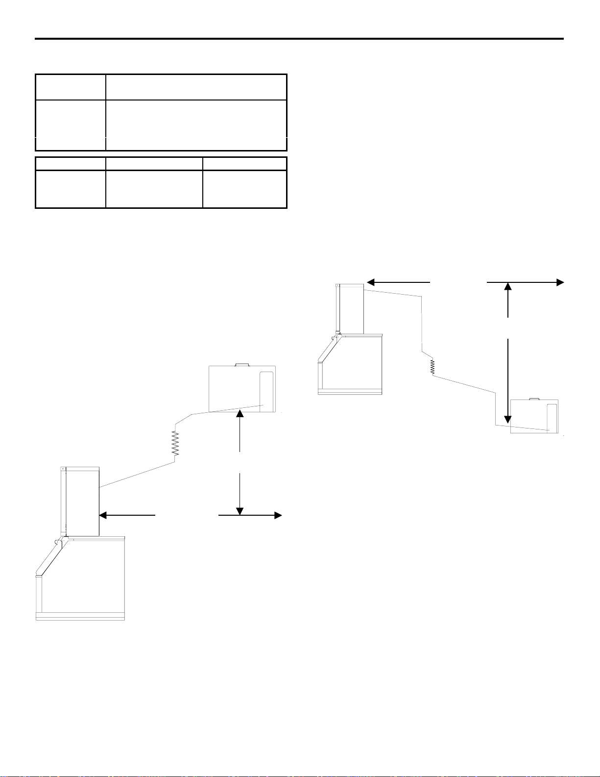
ROUTING PRE-CHARGED LINE SETS
General
Remote condensing unit installations consist of
vertical and horizontal line set distances between
the ice machine and the condensing unit. When
combined, they must fit within approved
specifications. The following guidelines, drawings
and calculation methods must be followed to verify
a proper installation.
35’ MAXIMUM
DISTANCE
Line set rise, drop, horizontal runs (or combinations
of these) in excess of the stated maximums will
exceed compressor start-up and design limits. This
will cause poor oil return to the compressor.
50’ MAXIMUM
DISTANCE
35’ MAXIMUM
DISTANCE
SV1722B
50’ MAXIMUM
DISTANCE
SV1722C
2-7
Page 19
Installation Instructions Section 2
Guidelines for Routing Pre-Charged Line Sets
First cut a circular hole in the wall or roof for tubing
routing. It is recommended that the line set end with
the service valves be connected to the ice machine.
The straight end will connect to the condensing unit
manifold.
Follow these guidelines when routing the refrigerant
lines. This will help insure proper performance and
service accessibility.
1. When installing horizontal runs refrigerant oil
must be free to return to the condensing unit.
Pitch all suction lines in the direction of
refrigerant flow (toward condensing unit),
allowing a minimum of ½” drop per 10’ of
horizontal run.
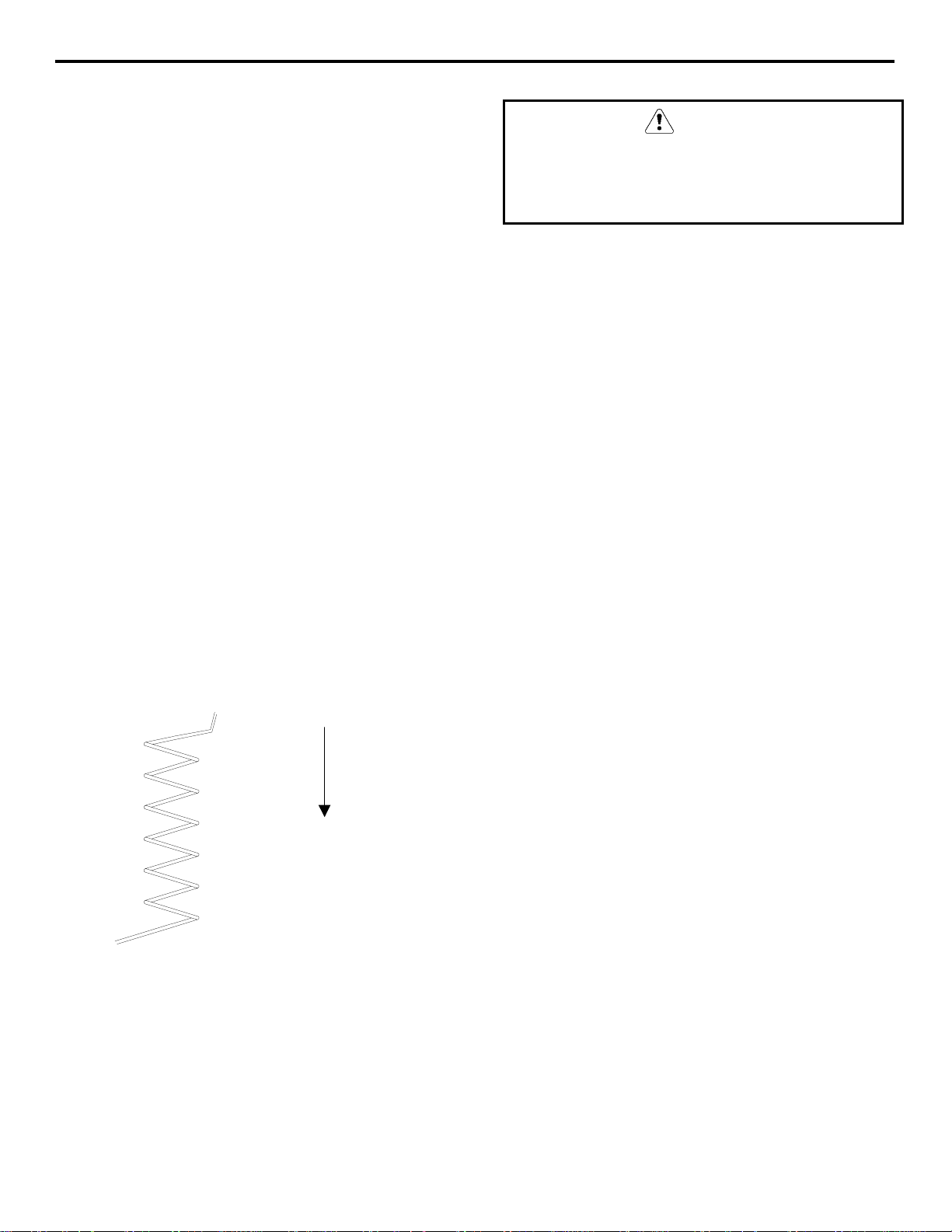
2. Route excess tubing in a supported downward
horizontal spiral as shown below. Do not coil
tubing vertically.
3. Insulate all suction lines, suction line shut-off
valves and components, to prevent condensation
and sweating.
If a line set has a rise followed by a drop, another
rise cannot be made. Likewise, if a line set has a
drop followed by a rise, another drop cannot be
made.
LENGTHENING OR REDUCING LINE SET LENGTHS
In most cases, by routing the line set properly,
shortening will not be necessary. When shortening
or lengthening is required, do so before connecting
the line set to the ice machine or condensing unit.
This prevents the loss of refrigerant.
The quick connect fittings on the line sets are
equipped with Schraeder valves. Use these valves to
recover any vapor charge from the line set. When
lengthening or shortening lines, follow good
refrigeration practices and insulate new tubing. Do
not change the tube sizes. Evacuate the lines and
place about 5-oz (142g) of vapor refrigerant charge
in each line.
CAUTION
4. Keep outdoor refrigerant line runs as short as
possible.
SUPPORT EXCESS TUBING
IN A DOWNWARD
HORIZONTAL SPIRAL
SV1204A
2-8
Page 20

Section 2 Installation Instructions
p
CONNECTING A LINE SET
1. Remove the dust caps from the line set,
manifold and ice machine.
2. Apply refrigeration oil to the threads on the
quick disconnect couplers before connecting.
3. Carefully thread the female fitting by hand, to
insure proper mating of the threads.
4. Tighten the couplings with a wrench until they
bottom out.
5. Turn an additional 1/4 turn to ensure proper
brass-to-brass seating. Torque to the following
specifications:
Liquid Line Suction Line
10-12 ft lb. (13.5-16.2 N•m) 35-45 ft lb. (47.5-61.0 N•m)
6. Check all fittings for leaks.
LINE SET SERVICE VALVE
Lines set service valves leave the factory in the
open position.
Verify all line set service valves are open and
insulated.
Important
Check condensing unit manual instructions to
verify that the receiver, suction and liquid line
service valves are in the open (backseated)
osition.
2-9
Page 21

Installation Instructions Section 2
Installation Checklist
Is the ice machine level?
Has all of the internal packing been removed?
Have all of the electrical and water connections
been made?
Has the supply voltage been tested and checked
against the rating on the nameplate?
Is there proper clearance around the ice
machine for servicing?
Has the ice machine been installed where
ambient temperatures will remain in the range
of 35° - 110°F (1.7° - 43.3°C)?
Has the ice machine been installed where the
incoming water temperature will remain in the
range of 33° - 90°F (0.6° - 32.2°C)?
Are the ice machine and bin drains vented?
Has the line set and condensing unit service
valves been opened?
Do the condenser fan motors operate properly?
Before Starting the Ice Machine
All Manitowoc ice machines are factory-operated
and adjusted before shipment. Normally, new
installations do not require any adjustment.
To ensure proper operation, follow the Operational
Checks on page 3-4 of this manual. Starting the ice
machine and completing the Operational Checks are
the responsibilities of the owner/operator.
ADJUSTMENTS AND MAINTENANCE
PROCEDURES OUTLINED IN THIS
MANUAL ARE NOT COVERED BY THE
WARRANTY.
AuCS
This optional accessory monitors ice-making cycles
and initiates self-cleaning procedures automatically.
The AuCS accessory can be set to automatically
clean or sanitize the ice machine every 2, 4 or 12
weeks. Refer to the AuCS Installation and
Owner/Operator Use and Care Guide for details.
Automatic Cleaning System
Has the remote condenser been located where
ambient temperatures will remain in the range
of -10° to 120°F (-6.6° to –49°C)?
Are the refrigeration lines run correctly?
Are all electrical leads free from contact with
refrigeration lines and moving equipment?
Has the owner/operator been instructed
regarding maintenance and the use of
Manitowoc Cleaner and Sanitizer?
Has the owner/operator completed the warranty
registration card?
Has the ice machine and bin been sanitized?
2-10
Page 22

Section 3 Ice Machine Operation
X
A
X
A
SV1696A
S
8A
SV1698A
S
0A
ction 3
Section 3
Ice Machine Operation
COMPONENT IDENTIFICATION
EXPANSION
VALVE
SUCTION
SOLENOID
VALVE
WATER
CURTAIN
AEROQUIP
FITTINGS
P520
LINE DRIER
CONTROL BO
ON/OFF/CLEAN
TOGGLE
SWITCH
ICE THICKNESS
PROBE
WATER LEVEL
PROBE
EROQUIP
FITTINGS
LINE DRIER
SUCTION
SOLENOID
VALVE
EXPANSION
VALVE
DISTRIBUTION
TUBE
P530
ICE THICKNESS
PROBE
WATER
CURTAIN
WATER
TROUGH
WATER
PUMP
CONTROL BO
ON/OFF/CLEAN
TOGGLE
SWITCH
WATER LEVEL
PROBE
ELECTRICAL
INLET
POTABLE
WATER INLET
POTABLE
WATER DRAIN
AEROQUIP
FITTINGS
HARVEST HEATER
THERMOSTAT
WATER
TROUGH
SUCTION
SOLENOID
VALVE
LINE DRIER
WATER
PUMP
V171
EXPANSION
VALVE
V172
POTABLE
WATER INLET
POTABLE
WATER DRAIN
ELECTRICAL
INLET
HARVEST HEATER
THERMOSTAT
EROQUIP
FITTINGS
LINE DRIER
SUCTION
SOLENOID
VALVE
EXPANSION
VALVE
3-1
Page 23

Ice Machine Operation Section 3
Ice Making Sequence of Operation
INITIAL START-UP OR START-UP AFTER AUTOMATIC SHUT-OFF
1. Water Purge
Before refrigeration begins the water pump and water
dump solenoid are energized for 45 seconds, to
completely purge the ice machine of old water. This
feature ensures that the ice making cycle starts with
fresh water.
FREEZE SEQUENCE
2. Prechill
The suction line solenoid is on (refrigerant starts to
flow) for 30 seconds prior to water flow, to prechill
the evaporator. The water fill valve turns on and
remains on until the water level probe is satisfied.
3. Freeze
The water pump restarts after the 30 second prechill.
An even flow of water is directed across the
evaporator and into each cube cell, where it freezes.
The water fill valve will cycle on and then off one
more time to refill the water trough.
When sufficient ice has formed, the water flow (not
the ice) contacts the ice thickness probe. After
approximately 10 seconds of continual water contact,
the harvest sequence is initiated. The ice machine
cannot initiate a harvest sequence until a 6-minute
freeze lock has been surpassed.
HARVEST SEQUENCE
4. Water purge
The water pump continues to run and the water dump
valve energizes for 45 seconds, to purge the water in
the sump trough. The water fill valve energizes for
the last 15 seconds of the 45-second water purge.
After the 45 second water purge, the water pump,
water fill valve, and water dump valve de-energize.
The evaporator heaters energize at the beginning of
the water purge, to warm the evaporator.
The suction line solenoid de-energizes at the
beginning of the water purge, to stop refrigerant flow
into the evaporator.
5. Harvest
The evaporator heaters remain energiz ed to warm the
evaporator, causing the cubes to slide as a sheet off
the evaporator and into the storage bin. The sliding
sheet of cubes swings the water curtain out, opening
the bin switch. The momentary opening and reclosing of the bin switch terminates the harvest
sequence and returns the ice machine to the freeze
sequence (steps 2-3).
AUTOMATIC SHUT-OFF
6. AUTOMATIC SHUT-OFF
When the storage bin is full at the end of a harvest
sequence, the sheet of cubes fails to clear the water
curtain and will hold it open. After the water curtain
is held open for 7 seconds, the ice machine shuts off.
3-2
The ice machine remains off until enough ice has
been removed from the storage bin to allow the ice to
fall clear of the water curtain. As the water curtain
swings back to the operating position, the bin switch
re-closes and the ice machine restarts (step 1).
Page 24

Section 3 Ice Machine Operation
THIS PAGE INTENTIONALLY LEFT BLANK
3-3
Page 25

Ice Machine Operation Section 3
A
Operational Checks
GENERAL
Your Manitowoc ice machine was factory-operated
and adjusted before shipment. Normally, a newly
installed ice machine does not require any
adjustment.
To ensure proper operation, always follow these
Operational Checks when starting the ice machine:
• for the first time
• after a prolonged out of service period
• after cleaning and sanitizing
Routine adjustments and maintenance procedures
outlined in this manual are not covered by the
warranty.
WATER LEVEL
The water level sensor is set to maintain the proper
water level above the water pump housing. The water
level is not adjustable.
If the water level is incorrect, check the water level
probe for damage (probe bent, etc.). Repair or replace
the probe as necessary.
ICE THICKNESS CHECK
The ice thickness probe is factory-set to maintain the
ice bridge thickness at 1/8” (3.2 mm).
NOTE: Make sure the water curtain is in place when
performing this check. It prevents water from
splashing out of the water trough.
1. Inspect the bridge connecting the cubes. It should
be about 1/8” (3.2 mm) thick.
2. If adjustment is necessary, turn the ice thickness
probe adjustment screw clockwise to increase
bridge thickness, or counterclockwise to decrease
bridge thickness.
NOTE: Turning the adjustment 1/3 of a turn will
change the ice thickness about 1/16” (1.5 mm).
DJUSTING
SCREW
3-4
SV1707A
Water Level Probe
1/8” (3.2MM)
ICE THICKNESS
SV1208
Ice Thickness Adjustment
Make sure the ice thickness probe wire and the
bracket do not restrict movement of the probe.
Page 26
Section 3 Ice Machine Operation
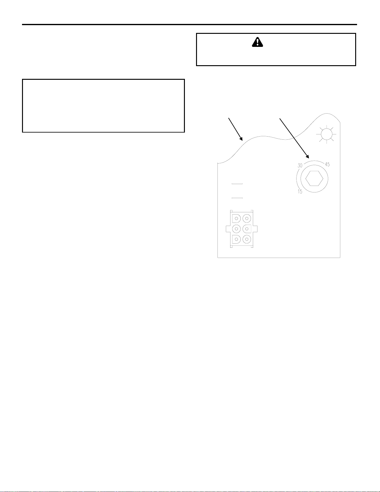
HARVEST SEQUENCE WATER PURGE
The harvest sequence water purge adjustment may be
used when the ice machine is hooked up to special
water systems, such as a de-ionized water treatment
system.
Important
The harvest sequence water purge is factory-set at
45 seconds. A shorter purge setting (with standard
water supplies such as city water) is not
recommended. This can increase water system
cleaning and sanitizing requirements.
• The harvest sequence water purge may be set to
15, 30, or 45 seconds.
• During the harvest sequence water purge, the
water fill valve energizes and de-energizes by
time. The water purge must be at the factory
setting of 45 seconds for the water fill valve to
energize during the last 15 seconds of the water
purge. If it is set to less than 45 seconds, the
water fill valve will not energize during the water
purge.
Disconnect the electrical power t o the ice m achine
at the electrical disconnect before proceeding.
For your safety, and to eliminate errors, we
recommend that a qualified service technician make
the harvest water purge adjustment.
CONTROL
BOARD
WARNING
WATER PURGE
ADJUSTMENT
Water Purge Adjustment
SV1617
3-5
Page 27

Ice Machine Operation Section 3
THIS PAGE INTENTIONALLY LEFT BLANK
3-6
Page 28

Section 4 Maintenance
Section 4
Maintenance
General
You are responsible for maintaining the ice machine
in accordance with the instructions in this manual.
Maintenance procedures are not covered by the
warranty.
WARNING
If you do not understand the procedures or the
safety precautions that must be followed, call your
local Manitowoc service representative to perform
the maintenance procedures for you.
We recommend that you perform the following
maintenance procedures every six months to ensure
reliable, trouble-free operation and maximum ice
production.
Ice Machine Inspection
WARNING
Disconnect electric power to the ice machine and
the remote condenser at the electric service switch
before cleaning the condenser.
Exterior Cleaning
Clean the area around the ice machine as often as
necessary to maintain cleanliness and efficient
operation.
Sponge any dust and dirt off the outside of the ice
machine with mild soap and water. Wipe dry with a
clean, soft cloth.
Heavy stains should be removed with stainless steel
wool. Never use plain steel wool or abrasive pads.
They will scratch the panels.
Cleaning the Condenser
WARNING
Disconnect electric power to the ice machine and
the remote condensing unit at the electric service
switch before cleaning the condenser.
A dirty condenser restricts airflow, resulting in
excessively high operating temperatures. This
reduces ice production and shortens component life.
Refer to Copeland’s cleaning instructions for details.
Check all water fittings and lines for leaks. Also,
make sure the refrigeration tubing is not rubbing or
vibrating against other tubing, panels, etc.
4-1
Page 29

Maintenance Section 4
Interior Cleaning and Sanitizing
GENERAL
Clean and sanitize the ice machine every six months
for efficient operation. If the ice machine requires
more frequent cleaning and sanitizing, consult a
qualified service company to test the water quality
and recommend appropriate water treatment.
If required, an extremely dirty ice machine may be
taken apart for cleaning and sanitizing.
CAUTION
Use only Manitowoc approved Ice Machine
Cleaner (part number 94-0546-3) and Sanitizer
(part number 94-0565-3). It is a violation of Federal
law to use these solutions in a manner inconsistent
with their labeling. Read and understand all labels
printed on bottles before use.
CAUTION
Do not mix Ice Machine Cleaner and Sanitizer
solutions together. It is a violation of Federal law to
use these solutions in a manner inconsistent with
their labeling.
SELF-CLEANING PROCEDURE (SeCS
Ice machine cleaner is used to remove lime scale or
other mineral deposits. It is not used to remove algae
or slime. Refer to “Self-Sanitizing Procedure” on the
next page for removal of algae and slime.
Step 1 Set the toggle switch to the OFF position
after ice falls from the evaporator at the end of a
Harvest cycle. Or, set the switch to the OFF position
and allow the ice to melt off the evaporator.
CAUTION
Never use anything to force ice from the ev aporator.
Damage may result.
Step 2 To start self-cleaning, move the toggle switch
to the CLEAN position.
Step 3 Add the proper amount of Manitowoc Ice
Machine Cleaner to the water trough.
Model Amount of Cleaner
P-520/P-530 5 ounces (150 ml)
)
WARNING
Wear rubber gloves and safety goggles (and/or face
shield) when handling Ice Machine Cleaner or
Sanitizer.
Step 4 The ice machine will automatically time out a
ten-minute cleaning cycle, followed by six rinse
cycles, and then stop. This entire cycle lasts
approximately 25 minutes.
Step 5 When the self-cleaning process stops, move
the toggle switch to the OFF position. Refer to “SelfSanitizing Procedure” on the next page.
Step 6 The ice machine may be set to start and finish
a self-cleaning procedure, and then automatically
start ice making again.
A. Wait about one minute into the self-cleaning
cycle, then move the toggle switch from
CLEAN to ICE position.
B. When the self-cleaning cycle is completed, an
ice making sequence will start automatically.
4-2
Page 30
Section 4 Maintenance
SELF-SANITIZING PROCEDURE
Use sanitizer to remove algae or slime. Do not use it
to remove lime scale or other mineral deposits.
Step 1 Set the toggle switch to the OFF position
after ice falls from the evaporator at the end of a
Harvest cycle. Or, set the switch to the OFF position
and allow the ice to melt off the evaporator.
Step 4 The ice machine will automatically time out a
ten-minute sanitizing cycle, followed by six rinse
cycles, and then stop. This entire cycle lasts
approximately 25 minutes.
Note: If the bin requires sanitizing, remove all of the
ice and sanitize it with a solution of 1 ounce (30 ml)
of sanitizer with up to 4 gallons (15 L) of water.
CAUTION
Never use anything to force ice from the
evaporator. Damage may result.
Step 2 To start self-sanitizing, move the toggle
switch to the CLEAN position.
Step 3 Add the proper amount of Manitowoc Ice
Machine Sanitizer to the water trough.
Model Amount of Sanitizer
P-520/P-530 3 ounces (90 ml)
Step 5 When the self-sanitizing process stops, move
the toggle switch to the ICE position to start making
ice again.
Step 6
A. The ice machine may be set to start and finish
a self-sanitizing procedure, and then
automatically start ice making again.
B. Wait about one minute into the sanitizing
cycle, then move the toggle switch from
CLEAN to ICE position.
C. When the self-sanitizing cycle is completed,
an ice making sequence will start
automatically.
4-3
Page 31

Maintenance Section 4
Removal of Parts for Cleaning/Sanitizing
1. Turn off the water supply to the ice machine at
the water service valve.
4. Use a soft-bristle brush or sponge (NOT a wire
brush) to carefully clean the parts.
WARNING
Disconnect electric power to the i ce machine at the
electric switch box before proceeding.
2. Remove the parts or components you want to
clean or sanitize. See the following pages for
removal procedures for these parts.
WARNING
Wear rubber gloves and safety goggles (and/or face
shield) when handling Ice Machine Cleaner or
Sanitizer.
3. Soak the removed part(s) in a properly mixed
solution.
Solution Type Water Mixed With
Cleaner 1 gal. (4 l) 16 oz (500 ml) cleaner
Sanitizer 4 gal. (15 l) 1 oz (30 ml) sanitizer
CAUTION
Do not mix Cleaner and Sanitizer solutions
together. It is a violation of Federal law to use these
solutions in a manner inconsistent with their
labeling.
CAUTION
Do not immerse the water pump motor in the
cleaning or sanitizing solution.
5. Use the solution and a brush to clean the top,
sides, and bottom evaporator extrusions; the
inside of the ice machine panels; and the entire
inside of the bin.
6. Thoroughly rinse all of the parts and surfaces
with clean water.
7. Install the removed parts.
8. Turn on the water and electrical supply.
4-4
Page 32

Section 4 Maintenance
Water Dump Valve
The water dump valve normally does not require
removal for cleaning.
To determine if removal is necessary:
1. Locate the water dump valve.
2. Set the toggle switch to ICE.
3. While the ice machine is in the freeze mode,
check the dump valve’s clear plastic outlet drain
hose for leakage.
A. If the dump valve is leaking, remove,
disassemble and clean it.
B. If the dump valve is not leaking, do not
remove it. Instead, follow the “Cleaning
Procedure” on page 4-2.
Follow the procedure below to remove the dump
valve.
Dump Valve Removal
WARNING
Disconnect the electric po wer to the ice machi ne at
the electric service switch box and turn off the
water supply before proceeding.
1. If so equipped, remove the water dump valve
shield from its mounting bracket.
2. Lift and slide the coil retainer cap from the top of
the coil.
3. Note the position of the coil assembly on the
valve for assembly later. Leaving the wires
attached, lift the coil assembly off the valve body
and the enclosing tube.
4. Press down on the plastic nut on the enclosing
tube and rotate it 1/4 turn. Remove the enclosing
tube, plunger, and plastic gasket from the valve
body.
Important
The plunger and the inside of the enclosing tube
must be completely dry before assembly.
NOTE: During cleaning, do not stretch, damage or
remove the spring from the plunger. If it is removed,
slide the spring’s flared end into the plunger’s slotted
top opening until the spring contacts the plunger
spring stop.
5. Remove the valve body.
6. Remove the tubing from the dump valve by
twisting the clamps off.
7. Remove the two screws securing the dump valve
and the mounting bracket.
PLUNGER
SPRING STOP
CAP
COIL
ENCLOSING
TUBE
SPRING
PLUNGER
DIAPHRAM
VALVE BODY
Dump Valve Disassembly
NOTE: At this point, the water dump valve can easily
be cleaned. If complete removal is desired, continue
with step 5.
4-5
Page 33

Maintenance Section 4
SV1619
Water Pump
WARNING
Disconnect the electric po wer to the ice machi ne at
the electric service switch box and turn off the
water supply.
1. Disconnect the water pump power cord.
LOOSEN SCREWS
Ice Thickness Probe
1. Compress the side of the ice thickness probe near
the top hinge pin and remove it from the bracket.
COMPRESS HINGE PIN TO
REMOVE
Ice Thickness Probe Removal
DISCONNECT
POWER CORD
SV1699A
Water Pump Removal
2. Disconnect the hose from the pump outlet.
3. Loosen the screws securing the pump mounting
bracket to the bulkhead.
4. Lift the pump and bracket assembly off the
screws.
NOTE: At this point, the ice thickness probe can
easily be cleaned. If complete removal is desired,
continue with step 2 below.
WARNING
Disconnect the electric po wer to the ice machin e at
the electric service switch box.
2. Disconnect the wire lead from the control board
inside the electrical control box.
4-6
Page 34

Section 4 Maintenance
V
SV1699
SV1623
Water Level Probe
1. Loosen the screw that holds the water level probe
in place. The probe can easily be cleaned at this
point without proceeding to step 2.
WARNING
Disconnect the electrical power to the ice m achine
at the electrical disconnect before proceeding.
2. If complete removal is required, disconnect the
wire lead from the control board inside the
electrical control box.
Follow the procedure below to remove the water inlet
valve.
WARNING
Disconnect the electric po wer to the ice machi ne at
the electric service switch box and turn off the
water supply before proceeding.
1. Remove the valve shield if necessary.
2. Remove the filter access screws that hold the
valve in place.
NOTE: The water inlet valve can be disassembled
and cleaned without disconnecting the incoming
water supply line to the ice machine.
3. Remove, clean, and install the filter screen.
4. If necessary, remove the enclosure tube access
screws to clean interior components.
B
Water Level Probe Removal
Water Inlet Valve
The water inlet valve normally does not require
removal for cleaning. Follow the instructions below
to determine if removal is necessary.
1. Set the ICE/OFF/CLEAN switch to OFF. Locate
the water inlet valve (in the water area of the ice
machine). It pours water into the water trough.
2. When the ice machine is off, the water inlet valve
must completely stop water flow into the
machine. Watch for water flow. If water flows,
remove, disassemble and clean the valve.
3. When the ice machine is on, the water inlet valve
must allow the proper water flow through it. Set
the toggle switch to ON. Watch for water flow
into the ice machine. If the water flow is slow or
only trickles into the ice machine remove
disassemble, and clean the valve.
ENCLOSURE
TUBE ACCESS
SCREWS
ELECTRICAL
SOLENOID
RESTRICTOR
(FLAT SIDE MUST
FACE OUT)
MOUNTING
PLATE
FILTER
ACCESS
SCREWS
FITTING
O-RING
FILTER
SCREEN
BODY
Exploded View of Water Inlet Valve
ALVE
ENCLOSURE
TUBE
SPRING
PIN
RUBBER
SEAL
4-7
Page 35

Maintenance Section 4
W
W
Water Distribution Tube
1. Disconnect the water hose from the distribution
tube.
2
1
THUMBSCRE
LOCATING PIN
SV1620
DISTRIBUTION
TUBE
THUMBSCRE
1. LIFT UP
2. SLIDE BACK
3. SLIDE TO RIGHT
3
Water Distribution Tube Removal
2. Loosen the two thumbscrews which secure the
distribution tube.
3. Lift the right side of the distribution tube up off
the locating pin, then slide it back and to the
right.
Water Curtain
1. Gently flex the curtain in the center and remove it
from the right side.
STEP 1
STEP 2
SV1213
Water Curtain Removal
2. Slide the left pin out.
CAUTION
Do not force this removal. Be sure the locating pin
is clear of the hole before sliding the distribution
tube out.
4. Disassemble for cleaning.
A. Twist both of the inner tube ends until the
tabs line up with the keyways.
B. Pull the inner tube ends outward.
INNER
TUBE
INNER
TUBE
TAB
KEYWAY
4-8
SV1211
Water Distribution Tube Disassembly
Page 36

Section 4 Maintenance
Water Treatment/Filtration
GENERAL
Local water conditions may require the installation of
a water treatment system to inhibit scale formation,
filter out sediment, and remove chlorine taste and
odor. Consult your local distributor for information
on Manitowoc’s full line of NSF-certified
Tri-Liminator filtration systems.
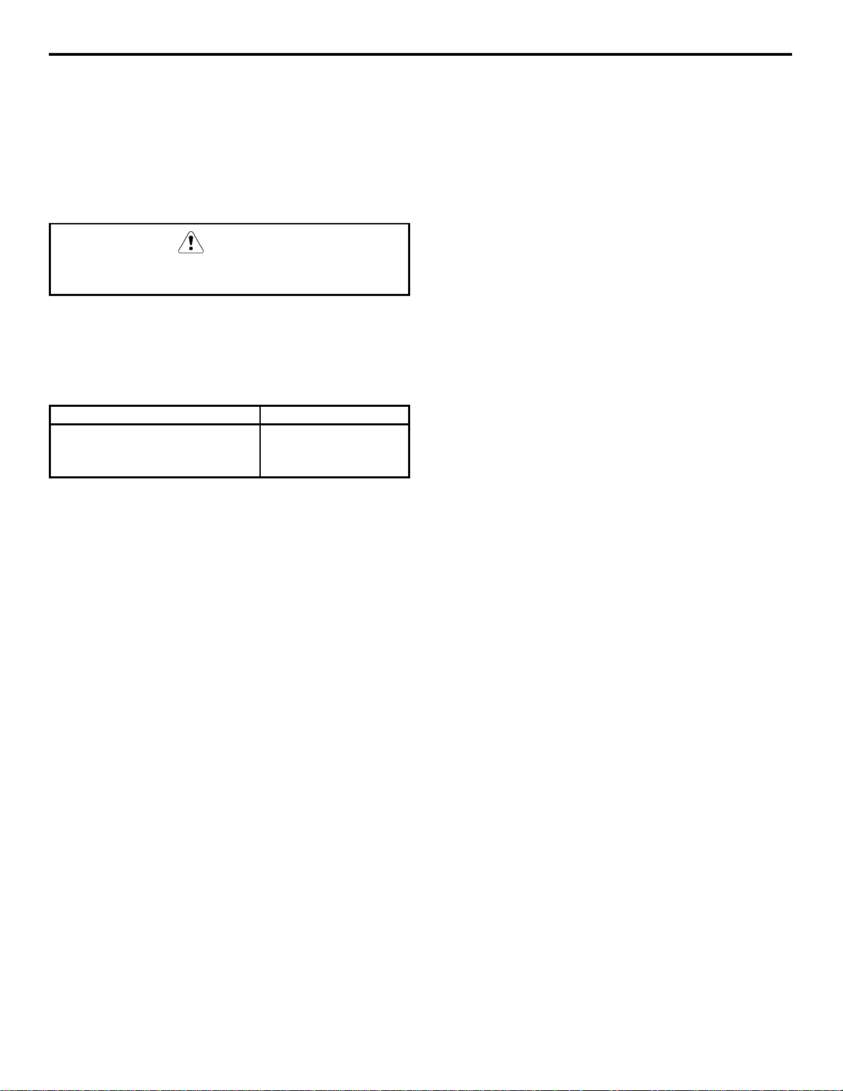
FILTER REPLACEMENT PROCEDURE
Tri-Liminator systems include a pre-filter and a
primary filter. For maximum filtration efficiency,
replace the primary filter cartridge every six months.
If the filter gauge reading drops below 20 psig prior
to six months usage, replace the pre-filter first.
3. Unscrew the housing from the cap.
4. Remove the used filter cartridge from the housing
and discard it.
5. Remove the O-ring from the housing groove.
Wipe the housing groove and the O-ring clean.
6. Lubricate the O-ring with petroleum jelly.
7. Press the O-ring into the housing groove.
8. Insert a new filter cartridge into the housing.
Make sure it slips down over the housing
standpipe.
9. Screw the housing on to the cap and carefully
hand-tighten it.
1. Turn off the water supply at the inlet shutoff
valve.
PRESSURE
RELEASE
BUTTON
OUTLET
SIDE
SEAL
O-RING
SEAL
CAP
CARTRIDGE
INLET
SIDE
PRE-FILTER
HOUSING
SHUT OFF
VALVE
PRIMARY
FILTER
CAUTION
Hand-tighten only. Do not overtighten. Do not use
a spanner wrench.
10. Repeat steps 3-9 for each filter housing.
11. Turn on the water supply to allow the housing
and filter to slowly fill with water.
12. Depress the pressure release button to release
trapped air from the housing.
13. Check for leaks.
Typical Tri-Liminator
Water Filtration System
2. Depress the pressure release button to relieve the
pressure.
4-9
Page 37

Maintenance Section 4
Removal from Service/Winterization
GENERAL
Special precautions must be taken if the ice machine
is to be removed from service for an extended
period of time or exposed to ambient temperatures
of 32°F (0°C) or below.
CAUTION
If water is allowed to remain in the ice machine in
freezing temperatures, severe damage to some
components could result. Damage of this nature is
not covered by the warranty.
Follow the applicable procedure below.
1. Move all Ice/Off/Clean toggle switches to the
off position.
2. Turn off the water supply.
3. Remove the water from the water trough.
4. Disconnect and drain the incoming ice-making
water line at the rear of the ice machine.
5. Move the Ice/Off/Clean toggle switch to Ice and
blow compressed air in the drain opening until
no more water comes out of the drain line.
6. Wait until the compressor starts then blow
compressed air in the incoming water opening
in the rear of the ice machine, until no more
water comes out of the inlet water lines.
7. Make sure water is not trapped in any of the
water lines, drain lines, distribution tubes, etc.
8. Disconnect the electric power at the circuit
breaker or the electric service switch.
9. Refer to Copeland manual for winterization of
condensing unit.
AUCS® ACCESSORY
Refer to the AUCS® Accessory manual for
winterization of the AUCS® Accessory.
4-10
Page 38

Section 5 Before Calling for Service
Section 5
Before Calling for Service
Checklist
If a problem arises during operation of your ice machine, follow the checklist below before calling for service.
Routine adjustments and maintenance procedures are not covered by the warranty.
Problem Possible Cause To Correct
Ice machine does not operate. No electrical power to the ice machine
or condensing unit.
ICE/OFF/CLEAN toggle switch set
improperly.
Water curtain stuck open. Curtain must be capable of swinging
Safety limit feature stopping the ice
machine.
Ice machine stops, and can be
restarted by moving the toggle
switch to OFF and back to ICE.
Ice machine does not release
ice or is slow to harvest.
Ice machine does not cycle
into harvest mode.
Ice quality is poor (soft or not
clear).
Safety limit feature stopping the ice
machine.
Ice machine is dirty. Clean and sanitize the ice machine.
Ice machine is not level. Level the ice machine.
The six-minute freeze time lock-in has
not expired yet.
Ice thickness probe is dirty. Clean and sanitize the ice machine.
Ice thickness probe wire is
disconnected.
Ice thickness probe is out of
adjustment.
Uneven ice fill (thin at top of
evaporator).
Poor incoming water quality. Contact a qualified service company
Water filtration is poor. Replace the filter.
Ice machine is dirty. Clean and sanitize the ice machine.
Water dump valve is not working. Disassemble and clean the water
Water softener is working improperly
(if applicable).
Replace the fuse/reset the
breaker/turn on the main switch.
Move the toggle switch to the ICE
position.
freely. See page 4-8.
Refer to “Safety Limit Feature” on the
next page.
Refer to “Safety Limit Feature” on the
next page.
See pages 4-2 and 4-3.
See page 2-2.
Wait for freeze lock-in to expire.
See pages 4-2 and 4-3.
Connect the wire.
Adjust the ice thickness probe.
See page 3-4.
See “Shallow or Incomplete Cubes”
on the next page.
to test the quality of the incoming
water and make appropriate filter
recommendations.
See pages 4-2 and 4-3.
dump valve. See page 4-5.
Repair the water softener.
Continued on next page...
5-1
Page 39

Section 5Before Calling for Service
Problem Possible Cause To Correct
Ice machine produces shallow
or incomplete cubes, or the ice
fill pattern on the evaporator is
incomplete.
Low ice capacity. Water inlet valve filter screen is dirty. Remove and clean the filter screen.
Ice thickness probe is out of
adjustment.
Water trough level is to high or too low. Check the water level. See page 3-4.
Water inlet valve filter screen is dirty. Remove and clean the filter screen.
Water filtration is poor. Replace the filter.
Hot incoming water. Connect the ice machine to a cold
Water inlet valve is not working. Remove the water inlet valve and
Incorrect incoming water pressure. Water pressure must be 20-80 psi
Water dump valve leaking Clean the dump valve
Ice machine is not level. Level the ice machine.
Incoming water supply is shut off. Open the water service valve.
Water inlet valve stuck open or leaking. Remove the water inlet valve and
The condenser is dirty. Clean the condenser.
Water dump valve leaking Clean the dump valve
Adjust the ice thickness probe.
See page 3-4.
See page 4-7.
water supply. See page 2-8.
clean it. See page 4-7.
(137.9 - 551.5 kPA).
See page 4-5
See page 2-2.
See page 4-7.
clean it. See page 4-7.
See page 4-5
Safety Limit Feature
In addition to the standard safety controls, your
Manitowoc ice machine features built-in safety
limits, which will stop the ice machine if conditions
arise which, could cause a major component failure.
Safety Limit Stand-By Mode:
The first time a safety limit shut down occurs, the
ice machine turns off for 60 minutes (Stand-by
Mode). The ice machine will then automatically
restart to see if the problem re-occurs. During the
Stand-By Mode the harvest light will be flashing. If
the same safety limit is reached a second time (the
problem has re-occurred) the ice machine will
initiate a safety limit shut down and remain off until
it is manually restarted. During a safety limit shut
down the harvest light will be flashing.
Before calling for service, re-start the ice machine
using the following procedure:
1. Move the ICE/OFF/CLEAN switch to OFF and
then back to ICE.
A. If the safety limit feature has stopped the ice
machine, it will restart after a short delay.
Proceed to step 2.
B. If the ice machine does not restart, see “Ice
machine does not operate” on the previous
page.
2. Allow the ice machine to run to determine if the
condition is reoccurring.
A. If the ice machine stops again, the condition
has recurred. Call for service.
B. If the ice machine continues to run, the
condition has corrected itself. Allow the ice
machine to continue running.
5-2
Page 40

Section 6 Service
Section 6
Electrical System
P MODEL POINT OF U S E
Ice Making Sequence of operation Chart
Control Board Relays Contactor
SEQUENCE
of
OPERATION
INITIAL START-UP/
START UP AFTER
AUTO SHUT-OFF:
1. Water Purge
12 3 4 5 3A
WATER
PUMP
on off off on off off
WATER
FILL
VALVE
CONTACTOR
COIL
WATER
DUMP
VALVE
SUCTION LINE
SOLENOID
EVAPORATOR
HEATERS
LENGTH
of
TIME
45
Seconds
FREEZE
SEQUENCE:
2. Prechill
3. Freeze
HARVEST
SEQUENCE:
4. Water Purge
5. Harvest
6.
AUTO SHUT-OFF
off
on
on
off off on off off on
off off off off off off
May
cycle
on/off
for first
45
seconds
Cycle on
then off
1 more
time
30 sec.
off on on off on
15 sec.
on
off off on off
off off on off
Control Board Safety Timers
Freeze Sequence:
• The ice machine is locked in the freeze
sequence for the first 6 minutes, not allowing the ice
thickness probe to initiate a harvest sequence.
• The maximum freeze time is 60 minutes, at
which time the control board automatically initiates
a harvest sequence (steps 4-5).
• The maximum "on time" for the water fill valve
is 6 minutes, at which time it automatically turns
off.
30
Seconds
Until
10 second
water contact
with ice
thickness
probe
Water purge
factory set at
45
Seconds
Bin switch
activation
Until
bin switch
re-closes
Harvest Sequence:
• The maximum "on time" for evaporator heaters
is 5.5 minutes, at which time the contactor will
automatically de-energize to shut the heaters
off.
• The maximum harvest time is 6-1/2 minutes, at
which time the control board automatically
terminates the harvest sequence. If the bin
switch is open, the ice machine will go to
Automatic shut-off (step 6). If the bin switch is
closed, the ice machine will go to the freeze
sequence (steps 2-3).
6-1
Page 41

Component Specifications and Diagnostics
Section 6Service
MAIN FUSE
Function
The control board fuse stops ice machine operation
if electrical components fail causing high amp draw.
Specifications
The main fuse is 250 Volt, 7 amp.
Check Procedure
WARNING
High (line) voltage is applied to the control board
(terminals #55 and #56) at all times. Removing
the control board fuse or moving the toggle
switch to OFF will not remove the power
supplied to the control board.
1. If the bin switch light is on with the water
curtain closed, the fuse is good.
WARNING
Disconnect electrical power to the entire ice
machine before proceeding.
2. Remove the fuse. Check the resistance across
the fuse with an ohmmeter.
Reading Result
Open (OL) Replace fuse
Closed (O) Fuse is good
BIN SWITCH
Function
Bin switch operation is controlled by movement of
the water curtain. The bin switch has two main
functions:
1. Terminating the harvest cycle and returning the
ice machine to the freeze cycle.
This occurs when the bin switch is opened and
closed again within 7 seconds during the harvest
cycle.
2. Automatic ice machine shut-off.
If the storage bin is full at the end of a harvest
cycle, the sheet of cubes fails to clear the water
curtain and holds it open. After the water curtain
is held open for 7 seconds, the ice machine shuts
off.
The ice machine remains off until enough ice is
removed from the storage bin to allow the sheet
of cubes to drop clear of the water curtain. As
the water curtain swings back to the operating
position, the bin switch closes and the ice
machine restarts.
Important
The water curtain must be ON (bin switch closed)
to start ice making.
Specifications
The bin switch is a magnetically operated reed
switch. The magnet is attached to the lower right
corner of the water curtain. The switch is attached
to the evaporator mounting bracket.
6-2
The bin switch is connected to a varying D.C.
voltage circuit. (Voltage does not remain constant.)
NOTE: Because of a wide variation in D.C. voltage,
it is not recommended that a voltmeter be used to
check bin switch operation.
Continued on next page
Page 42

Section 6 Service
Bin Switch Check Procedure
1. Set the toggle switch to OFF.
2. Watch the bin switch light on the control
board.
3. Move the water curtain toward the evaporator.
The bin switch must close. The bin switch
light “on” indicates the bin switch has closed
properly.
4. Move the water curtain away from the
evaporator. The bin switch must open. The bin
switch light “off” indicates the bin switch has
opened properly.
Ohm Test
1. Disconnect the bin switch wires to isolate the
bin switch from the control board.
2. Connect an ohmmeter to the disconnected bin
switch wires. Set the ohmmeter to the 10,000ohm scale.
3. Cycle the bin switch by opening and closing
the water curtain.
4. With the bin switch open: Resistance readings
of more than 30,000 ohms indicate a correctly
operating bin switch.
5. With the bin switch closed: Resistance
readings of less than 70 ohms indicates a
correctly operating bin switch.
Water Curtain Removal Notes
The water curtain must be on (bin switch closed)
to start ice making. While a freeze cycle is in
progress, the water curtain can be removed and
installed at any time without interfering with the
electrical control sequence.
If the ice machine goes into harvest sequence
while the water curtain is removed, one of the
following will happen:
• Water curtain remains off:
When the harvest cycle time reaches 3.5
minutes and the bin switch is not closed, the
ice machine stops as though the bin were full.
• Water curtain is put back on:
If the bin switch closes prior to reaching the
3.5 minute point, the ice machine immediately
returns to another freeze sequence prechill.
Important
Any reading between 70 and 30,000 ohms,
regardless of curtain position, indicates a
defective bin switch
GOOD
INFINITE
OHMS
METER
READS
(OL)
0 OHMS
70 OHMS
SWITCH CLOSED
GOOD
30,000 OHMS
SWITCH OPEN
BAD
Bin Switch Resistance Readings
6-3
Page 43

Section 6Service
ICE/OFF/CLEAN TOGGLE SWITCH
Function
This switch is used to place the ice machine in
ICE, OFF or CLEAN mode of operation.
Specifications
Double-pole, double-throw switch. The switch is
connected into a varying low D.C. voltage circuit.
Check Procedure
NOTE: Because of a wide variation in D.C.
voltage, it is not recommended that a voltmeter be
used to check toggle switch operation.
1. Inspect the toggle switch for correct wiring.
2. Isolate the toggle switch by disconnecting all
wires from the switch, or by disconnecting the
Molex connector and removing wire #69 from
the toggle switch.
3. Check across the toggle switch terminals using
a calibrated ohmmeter. Note where the wire
numbers are connected to the switch terminals,
or refer to the wiring diagram to take proper
readings.
Switch Setting Terminals Ohm Reading
66-62 Open
ICE 67-68 Closed
67-69 Open
66-62 Closed
CLEAN 67-68 Open
67-69 Closed
66-62 Open
OFF 67-68 Open
67-69 Open
4. Replace the toggle switch if ohm readings do
not match all three-switch settings.
HARVEST HEATER ELEMENT
Function
Warms the evaporator in the harvest cycle,
allowing the ice to release.
Specifications
Model Volt Amp Ohm
Upper 115 9.4 to 11.5 10.4 to 12.1
Lower 115 5.1 to 6.2 19.3 to 22.5
*Listed ohm values are at room temperature.
Check Procedure
1. Cycle the ice machine into a harvest sequence.
2. Attach an amp probe to one lead of the harvest
heater element and read amp draw. See
Specifications (above) for amp/ohm values.
Results of Check Action
Amperage
and ohm value
within specifications
No Amperage or
continuity
Amperage and/or
Ohm value not
within specifications
Element is OK
See Harvest Heater
Thermostat on next
page.
Replace the element
Replacement Procedure.
1. Remove evaporator assembly from ice
machine (see page 6-7).
2. Remove clips securing heater element to
evaporator tubing.
3. Align replacement heater element with
evaporator tubing.
4. Secure element to evaporator tubing with
clips.
6-4
5. Re-install evaporator assembly.
Page 44

Section 6 Service
N
HARVEST HEATER ELEMENT THERMOSTAT
Function
Safety control which de-energizes the harvest
heater contactor coil, when the evaporator
temperature exceeds the control setpoint.
The harvest heater thermostat is normally closed
and opens on an increase in temperature.
Specifications
Automatic reset
Cut-in 110°F (+/- 5°F) (thermostat closed).
Cut-out 125°F (+/- 5°F) (thermostat open).
Check Procedure
1. Insert a temperature probe next to the harvest
heater thermostat sensor.
2. Hook a voltmeter in parallel (across) the
harvest heater thermostat control, leaving
wires attached
This test must be completed within 5 1/2
minutes of starting the harvest sequence.
IMPORTANT:
3. Cycle the ice machine into a harvest cycle by
placing a jumper wire from the ice thickness
probe to ground (see page 6-13).
4. Temperature below listed specification:
Meter will read 0 volts and the heater
contactor coil will be energized.
LOW PRESSURE CUT-OUT CONTROL
Function
Energizes and de-energizes the compressor
contactor coil.
The LPC opens when the suction pressure reaches
the cut-out setpoint, and closes when the suction
pressures reach’s the cut-in setpoint.
Specifications
Adjustable cut-in and cut-out
Factory Setting Cut-in 25 psig Cut-out 3 psig
(These are minimum setpoints. The cut-in can be
increased when low ambient temperatures will not
be experienced.)
Check Procedure
NOTE: The suction pressure must exceed the cutin setpoint to close the switch. The switch will
then remain closed until the suction pressure drops
below the cut-out setpoint.
1. Attach an accurate gauge to the suction service
port on the condensing unit.
2. Hook a voltmeter in parallel across the low-
pressure control, leaving wires attached.
3. Front seat (close) the suction service valve on
the condensing unit. The suction pressure will
decrease causing the low-pressure control to
open at the listed specification. The voltage
reading across the low-pressure cut-out control
must be “line voltage”.
Temperature above listed specification:
Meter will read line voltage and the heater
contactor coil will be de-energized.
Replace the control if:
1. The control does not open at the specified
setpoint.
2. The control will not reset
4. Back seat (open) the suction service valve on
the condensing unit. The suction pressure will
increase causing the low-pressure control to
close at the listed specification. The voltage
reading across the low pressure cut-out control
must be “0 volts”.
5. Replace the low pressure cut-out control when
it does not open and close properly or does not
maintain proper settings.
CAUTION
ever set the Low Pressure Control to allow the
refrigeration system to enter a vacuum.
6-5
Page 45

Section 6Service
SUCTION SOLENOID VALVE
FUNCTION
Allows refrigerant flow through the evaporator
during the freeze cycle, and prevents refrigerant
flow through the evaporator in the harvest and
auto shut-off cycles.
SPECIFICATIONS
Coil 115 volt 50/60 cycle.
CHECK PROCEDURE
1. Move the Ice/Off/Clean toggle switch to the
Ice position.
2. Attach voltmeter at the suction solenoid valve
coil, leaving wires attached. The meter reading
must be line voltage and the suction solenoid
valve must be open.
3. Move the Ice/Off/Clean toggle switch to the
off position.
4. The meter reading must be 0 volts and the
suction solenoid valve must be closed.
LINE SET ISOLATION VALVES
FUNCTION
Isolates ice machine evaporator from refrigeration
system.
Allows discharge and suction pressure readings to
be taken at the schraeder valve fitting.
SPECIFICATIONS
Liquid Line 1/4″ inlet
1/4″ outlet
Suction Line 1/2″ inlet
1/2″ outlet
CHECK PROCEDURE
Remove 3/4″ cap to access valve.
To backseat valve (open):
Turn full counterclockwise.
To frontseat valve (closed):
Turn full clockwise.
Replace 3/4″ cap assuring a tight seal to eliminate
possibility of refrigerant leakage.
6-6
Page 46

Section 6 Service
EVAPORATOR REMOVAL
P-530
1. Disconnect power to the ice machine at the
service disconnect or breaker.
2. Remove front, back, side and top panels.
3. Disconnect wiring to the harvest heaters and
suction solenoid coil.
4. Remove bin switch from evaporator extrusion.
5. Frontseat (close) the isolation valves on the
liquid and suction line sets (see page 6-7).
6. Recover refrigerant from ice machine by
accessing schraeder valves on the aeroquip
fittings or line set isolation valves.
7. Disconnect line sets by unscrewing aeroquip
fittings. Follow procedure on page 2-9 when
reassembling.
8. Disconnect tubing and ice thickness probe
from water distribution tube.
9. Disconnect and remove the water distribution
tube.
P-520
1. Disconnect power to the ice machine at the
service disconnect or breaker.
2. Remove front, back, side and top panels.
3. Disconnect wiring to the harvest heaters and
suction solenoid coil.
4. Remove bin switch from evaporator extrusion.
5. Frontseat (close) the isolation valves on the
liquid and suction line sets (see page 6-7).
6. Recover refrigerant from ice machine by
accessing schraeder valves on the aeroquip
fittings or line set isolation valves.
7. Disconnect line sets by unscrewing aeroquip
fittings. Follow procedure on page 2-9 when
reassembling.
8. Disconnect ice thickness probe from water
distribution tube.
9. Remove water pump and water distribution
tube assembly.
10. Remove top angle bracket.
11. Remove the refrigeration cover plate
(located in the left-hand side of the evaporator
compartment) by removing two screws and
sliding forward..
12. Remove the two screws securing the Aeroquip
fitting assembly to the rear bulkhead.
13. Support the evaporator and remove the screws
securing the evaporator to the bulkhead.
14. Lift the evaporator assembly out through the
front of the ice machine
10. Remove water level probe.
11. Remove water trough.
12. Remove cover plate located in the upper left-
hand side of the evaporator compartment by
removing the screw.
13. Remove the four screws securing the line
drier/TXV assembly plate.
14. Remove screws attaching water inlet/dump
valve control box (complete removal is not
necessary).
15. Support the evaporator and remove the screws
securing the evaporator to the bulkhead.
16. Lift the evaporator assembly out through the
front of the ice machine
6-7
Page 47

ELECTRONIC CONTROL BOARD
V
)
Section 6Service
AC LINE VOLTAGE
ELECTRICAL PLUG
(NUMBERS MARKED ON
WIRES
MAIN FUSE (7A)
AUTOMATIC CLEANING
SYSTEM (AuCS)
ACCESSORY PLUG
ICE THICKNESS
PROBE
(3/16” CONNECTION)
WATER LEVEL
PROBE
JUMPER USED ON
Q1300/Q1800 ONLY
20
60
61
56
1C
1F
57
58
55
L1PRIMARY
POWER SUPPLY
N 115
L2 208-230V
CLEAN LIGHT
YELLOW
WATER LEVEL
PROBE LIGHT
GREEN
BIN SWITCH LIGHT
GREEN
HARVEST LIGHT/
SAFETY LIMIT
CODE LIGHT
RED
1G
DC LOW VOLTAGE
ELECTRICAL PLUG
(NUMBERS MARKED
ON WIRES)
67
62
63
68
65
Control Board
General
P-Model control boards use a dual voltage
transformer. This means only one control board is
needed for both 115V and 208-230V use.
The control board along with inputs controls all
electrical components, including the ice machine
sequence of operation. Prior to diagnosing, you
must understand how the inputs affect the control
board operation.
Refer to specific component specifications
(inputs), wiring diagrams and ice machine
sequence of operation sections for details.
SV1588
As an example, refer to “Ice Thickness Probe” in
the service section of this manual for information
relating to how the probe and control board
functions together.
This section will include items such as:
• How a harvest cycle is initiated
• How the harvest light functions with the probe
• Freeze time lock-in feature
• Maximum freeze time
• Diagnosing ice thickness control circuitry
6-8
Page 48

Section 6 Service
SAFETY LIMITS
General
In addition to standard safety controls, such as high
pressure cut-out, the control board has two built in
safety limit controls which protect the ice machine
from major component failures.
Safety Limit #1: If the freeze time reaches 60
minutes, the control board automatically initiates a
harvest cycle. If three consecutive 60-minute freeze
cycles occur, the ice machine stops.
Safety Limit #2: If the harvest time reaches 3.5
minutes, the control board automatically returns the
ice machine to the freeze cycle. If three consecutive
3.5 minute harvest cycles occur, the ice machine
stops.
Determining Which Safety Limit
Stopped The Ice Machine
When a safety limit condition causes the ice machine
to stop, the harvest light on the control board
continually flashes on and off. Use the following
procedures to determine which safety limit has
stopped the ice machine.
1. Move the toggle switch to OFF.
2. Move the toggle switch back to ICE.
3. Watch the harvest light. It will flash one or two
times, corresponding to safety limits 1 and 2, to
indicate which safety limit stopped the ice
machine.
After safety limit indication, the ice machine will
restart and run until a safety limit is exceeded again.
Analyzing Why Safety Limits
May Stop the Ice Machine
According to the refrigeration industry, a high
percentage of compressors fail as a result of external
causes. These can include: flooding or starving
expansion valves, dirty condensers, water loss to the
ice machine, etc. The safety limits protect the ice
machine (primarily the compressor) from external
failures by stopping ice machine operation before
major component damage occurs.
The safety limit system is similar to a high pressure
cut-out control. It stops the ice machine, but does not
tell what is wrong. A service technician must analyze
the system to determine what caused the high
pressure cut-out, or a particular safety limit, to stop
the ice machine.
The safety limits are designed to stop the ice machine
prior to major component failures, most often a minor
problem or something external to the ice machine.
This may be difficult to diagnose, as many external
problems occur intermittently.
Example: An ice machine stops intermittently on
safety limit #1 (long freeze times). The problem
could be a low ambient temperature at night, a water
pressure drop, the water is turned off one night a
week, etc.
When a high pressure cut-out or a safety limit stops
the ice machine, they are doing what they are
supposed to do. That is, stopping the ice machine
before a major component failure occurs.
Refrigeration and electrical component failures may
also trip a safety limit. Eliminate all electrical
components and external causes first. If it appears
that the refrigeration system is causing the problem,
use Manitowoc’s Refrigeration System Operational
Analysis Table, along with detailed charts, checklists,
and other references to determine the cause.
The following checklists are designed to assist the
service technician in analysis. However, because
there are many possible external problems, do not
limit your diagnosis to only the items listed.
6-9
Page 49

Safety Limit #1
Freeze time exceeds 60 minutes for 3 consecutive freeze cycles.
Possible Cause Check/Correct
Improper installation • See section 2 “Installation Instructions”
Water system • Low water pressure (20 psi min.)
• High water pressure (80 psi max.)
• High water temperature (90°F/32.2°C max.)
• Clogged water distribution tube
• Dirty/defective water fill valve
• Dirty/defective water dump valve
• Defective water pump
Electrical system • Ice thickness probe out of adjustment
• Harvest cycle not initiated electrically
• Harvest heater contactor not energizing
• Compressor electrically non-operational
Restricted condenser
air flow
Refrigeration system • Non-Manitowoc components
• High inlet air temperature (110°F/43.3°C max.)
• Dirty condenser fins
• Defective fan motor
• Improper refrigerant charge
• Defective head pressure control
• Defective compressor
• TXV starving or flooding (check bulb mounting)
• Non-condensibles in refrigeration system
• Plugged or restricted high side refrigerant lines or component
Section 6Service
Safety Limit #2
Harvest time exceeds 6.5 minutes for 3 consecutive harvest cycles.
Possible Cause Check/Correct
Improper installation • See section 2 “Installation Instructions”
Water system • Water area (evaporator) dirty
• Dirty/defective water dump valve
• Water freezing behind evaporator
• Plastic extrusions and gaskets not securely mounted to the evaporator
• Low water pressure (20 psi min.)
• Loss of water from sump area
• Clogged water distribution tube
• Dirty/defective water fill valve
• Defective water pump
Electrical system • Ice thickness probe out of adjustment
• Ice thickness probe dirty
• Bin switch defective
• Premature harvest
• Defective harvest heater element
Refrigeration system • Non-Manitowoc components
• Improper refrigerant charge
• Defective head pressure control valve
• TXV flooding (check bulb mounting)
6-10
Page 50

Section 6 Service
Safety Limit Notes
• Because there are many possible external
problems, do not limit your diagnosis to only
the items listed in this chart.
• A continuous run of 100 harvests
automatically erases the safety limit code.
• The control board will store and indicate only
one safety limit – the last one exceeded
• If the toggle switch is moved to the off
position and then back to the ICE position
prior to reaching the 100-harvest point, the last
safety limit exceeded will be indicated.
• If the harvest light did not flash prior to the ice
machine restarting, then the ice machine did
not stop because it exceeded a safety limit.
Safety Limit Stand-By Mode:
The first time a safety limit shut down occurs, the
ice machine turns off for 60 minutes (Stand-by
Mode). The ice machine will then automatically
restart to see if the problem re-occurs. During the
Stand-By Mode the harvest light will be flashing.
If the same safety limit is reached a second time
(the problem has re-occurred) the ice machine will
initiate a safety limit shut down and remain off
until it is manually restarted. During a safety limit
shut down the harvest light will be flashing.
Re-start the ice machine using the following
procedure:
1. Move the ICE/OFF/CLEAN switch to OFF
and then back to ICE.
A. If the safety limit feature has stopped the
ice machine, it will restart after a short
delay. Proceed to step 2.
B. If the ice machine does not restart, see “Ice
machine does not operate” Section 5.
2. Allow the ice machine to run to determine if
the condition is reoccurring.
If the ice machine stops again, the condition has
reoccurred, and the cause must be determined.
If the ice machine continues to run, the condition
has corrected itself. Allow the ice machine to
continue running.
6-11
Page 51

Ice Thickness Probe (Harvest Initiation)
A
HOW THE PROBE WORKS
Manitowoc’s electronic sensing circuit does not
rely on refrigerant pressure, evaporator
temperature, water levels or timers to produce
consistent ice formation.
Section 6Service
To allow the service technician to initiate a harvest
cycle without delay, this feature is not used on the
first cycle after moving the toggle switch OFF and
back to ICE.
As ice forms on the evaporator, water (not ice)
contacts the ice thickness probe. After the water
completes this circuit across the probe
continuously for 6-10 seconds, a harvest cycle is
initiated.
SV1589G
Ice Thickness Probe
HARVEST/SAFETY LIMIT LIGHT
This light’s primary function is to be on as water
contacts the ice thickness probe during the freeze
cycle, and remain on throughout the entire harvest
cycle. The light will flicker as water splashes on
the probes.
MAXIMUM FREEZE TIME
The control system includes a built-in safety that
will automatically cycle the ice machine into
harvest after 60 minutes in the freeze cycle.
ICE THICKNESS CHECK
The ice thickness probe is factory-set to maintain
the ice bridge thickness at 1/8” (3.2 mm).
NOTE: Make sure the water curtain is in place
when performing this check. It prevents water
from splashing out of the water trough.
1. Inspect the bridge connecting the cubes. It
should be about 1/8” (3.2 mm) thick.
2. If adjustment is necessary, turn the ice
thickness probe adjustment screw clockwise to
increase bridge thickness, or counterclockwise
to decrease bridge thickness.
NOTE: Turning the adjustment 1/3 of a turn will
change the ice thickness about 1/16” (1.5 mm).
DJUSTING
SCREW
The light’s secondary function is to continuously
flash when the ice machine is shut off on a safety
limit, and to indicate which safety limit shut off
the ice machine.
FREEZE TIME LOCK-IN FEATURE
The ice machine control system incorporates a
freeze time lock-in feature. This prevents the ice
machine from short cycling in and out of harvest.
The control board locks the ice machine in the
freeze cycle for six minutes. If water contacts the
ice thickness probe during these six minutes, the
harvest light will come on (to indicate that water is
in contact with the probe), but the ice machine will
stay in the freeze cycle. After the six minutes are
up, a harvest cycle is initiated. This is important to
remember when performing diagnostic procedures
on the ice thickness control circuitry.
6-12
1/8” (3.2MM)
ICE
THICKNESS
SV1208
Ice Thickness Check
Make sure the ice thickness probe wire and the
bracket do not restrict movement of the probe.
Page 52

Section 6 Service
A
GROU
JU
DIAGNOSING ICE THICKNESS CONTROL CIRCUITRY
Ice Machine Does Not Cycle Into Harvest When Water Contacts The Ice Thickness Control Probe
Step 1 Bypass the freeze time lock-in feature by moving the ICE/OFF/CLEAN switch to OFF and back to
ICE. Wait until the water starts to flow over the evaporator.
Step 2 Clip the jumper wire leads to the ice thickness probe and any cabinet ground.
EVAPORATOR
Monitoring of Harvest Light Correction
The harvest light comes on, and 6-10 seconds later,
ice machine cycles from freeze to harvest.
The harvest light comes on but the ice machine
stays in the freeze sequence.
The harvest light does not come on. Proceed to Step 3, below.
ICE THICKNESS PROBE
ND
MPER WIRE
SV1592G
1C
Step 2
Step 2 Jumper wire connected from probe to ground
The ice thickness control circuitry is functioning
properly. Do not change any parts.
The ice thickness control circuitry is functioning
properly. The ice machine is in a six-minute freeze
time lock-in. Verify step 1 of this procedure was
followed correctly.
CLEAN LIGHT
WATER LEVEL LIGHT
HARVEST/SAFETY LIMIT
SV1588
LIGHT
Step 3 Disconnect the ice thickness probe from the control board at terminal 1C. Clip the jumper wire leads
to terminal 1C on the control board and any cabinet ground. Monitor the harvest light.
GROUND
CLEAN LIGHT
ICE THICKNESS PROBE
EVAPORATOR
SV1591G
JUMPER WIRE
1C
Step 3
Step 3 Jumper wire connected from control board terminal 1C to ground
Monitoring of Harvest Light Correction
The harvest light comes on, and 6-10 seconds later,
The ice thickness probe is causing the malfunction.
ice machine cycles from freeze to harvest.
The harvest light comes on but the ice machine
stays in the freeze sequence.
The control circuitry is functioning properly. The ice
machine is in a six-minute freeze time lock-in (verify
step 1 of this procedure was followed correctly).
The harvest light does not come on. The control board is causing the malfunction.
WATER LEVEL LIGHT
HARVEST/SAFETY LIMIT
LIGHT
SV1588G
6-13
Page 53

Section 6Service
Ice Machine Cycles Into Harvest Before Water Contact With The Ice Thickness Probe
Step 1 Disconnect the ice thickness probe from the control board at terminal 1C.
Step 2 Bypass the freeze time lock-in feature by moving the ICE/OFF/CLEAN switch to OFF and back to
ICE. Wait until the water starts to flow over the evaporator, then monitor the harvest light.
CLEAN LIGHT
ICE THICKNESS PROBE
1C
WATER LEVEL LIGHT
HARVEST/SAFETY LIMIT
LIGHT
Step 2 Disconnect probe from control board terminal 1C
Monitoring of Harvest Light Correction
The harvest light stays off and the ice machine
remains in the freeze sequence.
The harvest light comes on, and 6-10 seconds later,
the ice machine cycles from freeze to harvest.
Step 2
The ice thickness probe is causing the malfunction.
Verify that the Ice Thickness probe is adjusted
correctly.
The control board is causing the malfunction.
SV1588SV1591G
6-14
Page 54

Section 6 Service
Water Level Control Circuitry
WATER LEVEL PROBE LIGHT
The water level probe circuit can be monitored by
watching the water level light. The water level
light is on when water contacts the probe, and off
when no water is in contact with the probe. The
water level light functions any time power is
applied to the ice machine, regardless of toggle
switch position.
WATER LEVEL
ABOVE HOUSING
IMPELLER HOUSING
WATER
WATER PUMP
110°°°°
PUMP
WATER LEVEL
PROBE
PUMP
OUTLET
SV1616
FREEZE CYCLE WATER LEVEL SETTING
During the freeze cycle, the water level probe is
set to maintain the proper water level above the
water pump housing. The water level is not
adjustable. If the water level is incorrect, check the
water level probe for damage (probe bent, etc.).
Repair or replace the probe as necessary.
FREEZE CYCLE CIRCUITRY
Manitowoc’s electronic sensing circuit does not
rely on float switches or timers to maintain
consistent water level control. During the freeze
cycle, the water inlet valve energizes (turns on)
and de-energizes (turns off) in conjunction with
the water level probe located in the water trough.
During the first 45 seconds of the Freeze Cycle:
The water inlet valve is on when there is no water
in contact with the water level probe.
The water inlet valve turns off after water contacts
the water level probe for 3 continuous seconds.
The water inlet valve will cycle on and off as
many times as needed to fill the water trough.
After 45 seconds into the Freeze Cycle:
The water inlet valve will cycle on, and then off
one more time to refill the water trough. The water
inlet valve is now off for the duration of the freeze
sequence.
HARVEST CYCLE CIRCUITRY
The water level probe does not control the water
inlet valve during the harvest cycle. During the
harvest cycle water purge, the water inlet valve
energizes (turns on) and de-energizes (turns off)
strictly by time. The harvest water purge
adjustment dial may be set at 15, 30 or 45 seconds.
CONTROL BOARD
HARVEST WATER PURGE
ADJUSTMENT
WATER INLET VALVE SAFETY SHUT-OFF
The water inlet valve will energize only during the
first six minutes of the freeze cycle. In the event of
a water level probe failure, this feature limits the
water inlet valve to a six-minute on time.
Regardless of the water level probe input, the
control board automatically shuts off the water
inlet valve if it remains on for 6 continuous
minutes. This is important to remember when
performing diagnostic procedures on the water
level control circuitry.
SV1617
NOTE: The water purge must be at the factory
setting of 45 seconds for the water inlet valve to
energize during the last 15 seconds of the Water
Purge. If set at 15 or 30 seconds the water inlet
valve will not energize during the harvest water
purge
6-15
Page 55

Section 6Service
Y
OW
G
G
DIAGNOSING FREEZE CYCLE POTABLE WATER LEVEL CONTROL CIRCUITRY
Problem: Water Trough Overfilling During The Freeze Cycle
Step 1 Start a new freeze sequence by moving the ICE/OFF/CLEAN toggle switch to OFF, then back to
ICE.
Important
This restart must be done prior to performing diagnostic procedures. This assures the ice machine is not in
a freeze cycle water inlet valve safety shut-off mode. You must complete the entire diagnostic procedure
with-in 6 minutes of starting.
Step 2 Wait until the freeze cycle starts (approximately 45 seconds, the freeze cycle starts when the water
pump energizes) then connect a jumper from the water level probe to any cabinet ground.
Important
For the test to work properly you must wait until the freeze cycle starts, prior to connecting the jumper
wire. If you restart the test you must disconnect the jumper wire, restart the ice machine, (step 1) and then
reinstall the jumper wire after the water pump starts.
CLEAN LIGHT
WATER LEVEL LIGHT
BIN SWITCH LIGHT
HARVEST/SAFETY LIMIT LIGHT
SV1588SV1621G
GROUND
JUMPER
ELL
REEN
REEN
RED
1C
1F
1G
Step 2
Step 2 Jumper wire connected from probe to ground
Is water flowing
into the water
trough?
The Water Level
Light is:
no on De-Energized
yes on De-En ergized
yes off Energized Proceed to step 3.
The Water Inlet
Valve Solenoid
Coil is:
This is normal operation.
Do not change any parts.
The water inlet valve is
causing the problem.
Cause
Continued on next page…
6-16
Page 56

Section 6 Service
Y
W
G
G
Problem: Water Trough Overfilling During The Freeze Cycle (continued)
Step 3 Allow ice machine to run. Disconnect the water level probe from control board terminal 1F, and
connect a jumper wire from terminal 1F to any cabinet ground.
Remember if you are past 6 minutes from starting, the ice machine will go into a freeze cycle water inlet
valve safety shut-off mode, and you will be unable to complete this test. If past 6 minutes you must restart
this test by disconnecting the jumper wire, restarting the ice machine, (step 1) and then reinstalling the
jumper wire to terminal 1F, after the water pump starts.
CLEAN LIGHT
WATER LEVEL LIGHT
BIN SWITCH LIGHT
HARVEST/SAFETY LIMIT LIGHT
SV1588
GROUND
JUMPER
1C
1F
1G
ELLO
REEN
REEN
RED
Step 3
Step 3 Jumper wire connected from control board terminal 1F to ground
Is water flowing
into the water
trough?
The Water Level
Light is:
no on De-Energized
yes off Energized The control board is causing the problem.
yes on De-Energized The water fill valve is causing the problem.
The Water Inlet
Valve Solenoid
Coil is:
Cause
The water level probe is causing the problem.
Clean or replace the water level probe.
6-17
Page 57

Section 6Service
Y
OW
Problem: Water Will Not Run Into The Sump Trough During The Freeze Cycle
Step 1 Verify water is supplied to the ice machine, and then start a new freeze sequence by moving the
ICE/OFF/CLEAN toggle switch to OFF then back to ICE.
Important
This restart must be done prior to performing diagnostic procedures. This assures the ice machine is not in
a freeze cycle water inlet valve safety shut-off mode. You must complete the entire diagnostic procedure
with-in 6 minutes of starting.
Step 2 Wait until the freeze cycle starts (approximately 45 seconds, the freeze cycle starts when the water
pump energizes), and then refer to chart.
Step 2 Checking for normal operation
Is water flowing
into the water
trough?
The Water Level
Light is:
yes off Energized This is Normal Operation don’t change any parts
no on or off
The Water Inlet
Valve Solenoid
Coil is:
Energized
Or
De-Energized
Cause
Proceed to step 3
Step 3 Leave the ice machine run, then disconnect the water level probe from control board terminal 1F.
Important
For the test to work properly you must wait until the freeze cycle starts, prior to disconnecting the water
level probe. If you restart the test you must reconnect the water level probe, restart the ice machine,
(step 1) and then disconnect the water level probe after the water pump starts.
DISCONNECT
WATER LEVEL
PROBE FROM
TERMINAL 1F
ELL
GREEN
GREEN
RED
1C
1F
1G
CLEAN LIGHT
WATER LEVEL LIGHT
BIN SWITCH LIGHT
HARVEST/SAFETY
LIMIT LIGHT
SV1588SV1621G
Step 3
Step 3 Disconnect water level probe from control board terminal 1F
Is water flowing
into the water
trough?
The Water Level
Light is:
yes off Energized
no off Energized The water inlet valve is causing the problem.
no on or off De-Energized The control board is causing the problem.
The Water Inlet
Valve Solenoid
Coil is:
Cause
The water level probe is causing the problem.
Clean or replace the water level probe.
6-18
Page 58
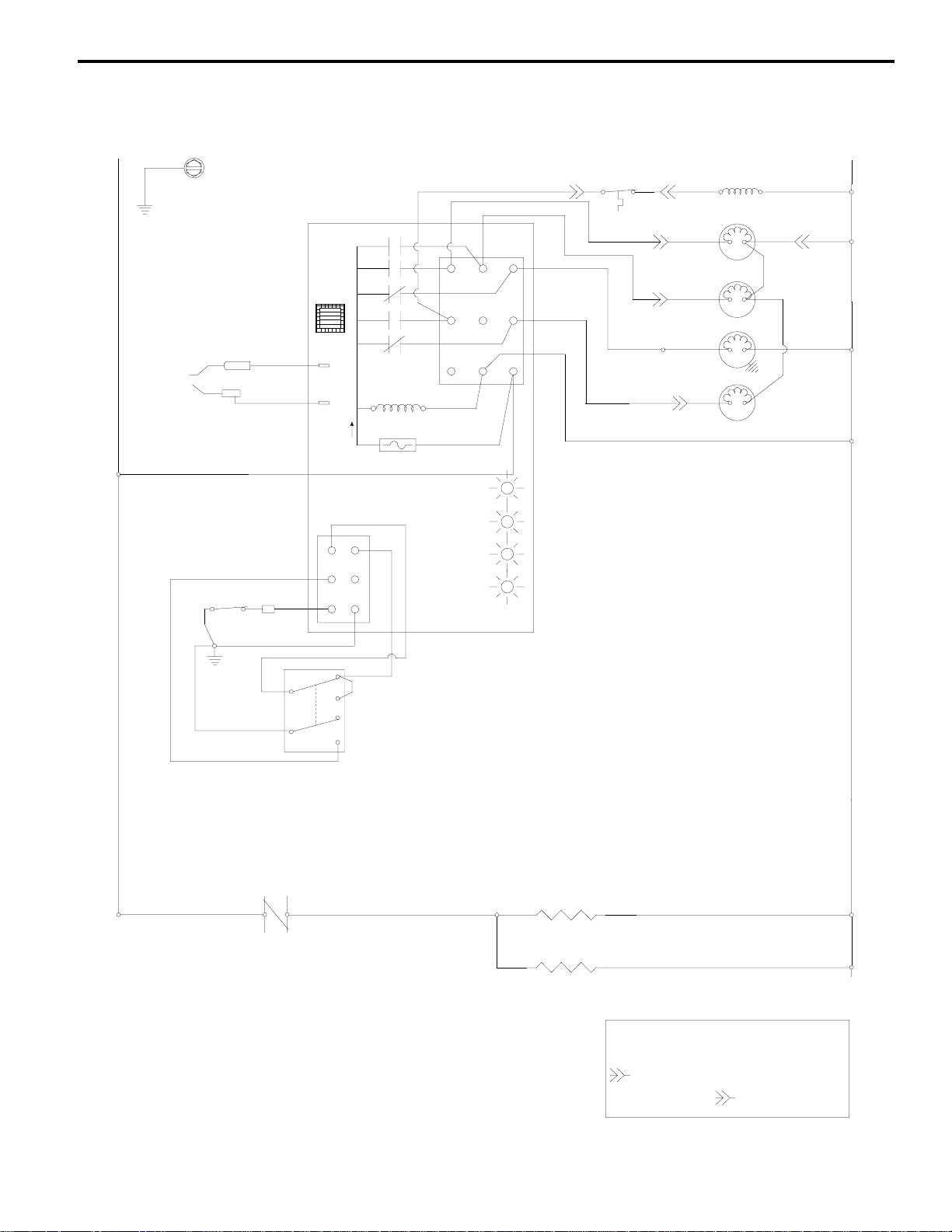
Section 6 Service
Wiring Diagram P520/P530 Ice Machines
Caution: Disconnect power before working
L1
ICE THICKNESS
PROBE
WATER LEVEL
PROBE
AUCS
1C
1F
Point of Use
on electrical circuitry.
Drawing shown during freeze cycle
2
4
1
3
5
TRANSFORMER
(61)
AUTO RESET
125F C.O.
110F C.I.
(36)
(58)
(57)
(37)
(60)
(30)
TB31
See serial plate for voltage
CONTACTOR
COIL
(35)
DUMP
SOLENOID
(76)
WATER FILL
SOLENOID
(77)
WATER PUMP
(98)
SUCTION
SOLENOID
(73)
(79)
(74)
(75)
(80)
(75)
(99)
L2 (N)
TB30
TB30
TB30
TB35
TB35
(64) BIN
(55)
SWITCH
(67)
(66)
CONTACTOR
CONTACTS
(42)
LOW D.C. VOLTAGE
(62)
(63)
TOGGLE SWITCH
(65)
PLUG
(68)
(69)
(62)
FUSE
7A
ICE
OFF
CLEAN
YELLOW
GREEN
GREEN
RED
CLEAN MODE
UPPER HEATER
(31)
(56)
WATER LEVEL SWITCH
CURTAIN SWITCH
HARVEST /
SAFTY CODE
(32)
TB30
TB30
(33)
elept
6/20/97LM
rev. 9/19/97
LOWER HEATER
(34)
TB - TERMINAL BOARD CONNECTION
( ) - WIRE NUMBER DESIGNATION
(# IS MARKED AT EACH END OF WIRE)
- BULKHEAD MULTIPIN CONNECTOR
ELECTRICAL
BOX SIDE
BACK OF
MACHINE
TB30
6-19
Page 59

P520/P530
S
6A
Tubing Diagram Typical Installation
LIQUID LINE DRIER
LINE SET
ISOLATION
VALVES
LIQUID LINE DRIER EXPANSION VALVE
LINE SET
ISOLATION
VALVES
Section 6Service
EVAPORATOR
EVAPORATOR
LIQUID LINE
MANIFOLD
SUCTION LINE
MANIFOLD
SUCTION LINE
KING VALVE
LIQUID LINE KING
ACCUMULATOR
VALVE
COMPRESSOR
LIQUID LINE
FILTER DRIER
LINE SET
ISOLATION
VALVES
RECEIVER
LIQUID LINE DRIER EXPANSION VALVE
EXPANSION VALVE
HEAD PRESSURE
CONTROL VALVE
EVAPORATOR
CONDENSER
V172
6-20
Page 60

Section 6 Service
24 Hour Production Charts
P520/P530 ICE MACHINES
Ice machine freeze and harvest times will vary depending on the number of ice machines operating, and
which stage of a cycle each machine is in. With an ambient temperature of 90°F and water temperature of
50°F, freeze times will range from 8 minutes* with one ice machine operating, to 22 minutes* with 4 ice
machines operating. * Based on a slab weight of 4.02lb to 4.12lbs.
Individual Ice Capacity (Lb./24 Hour)
700
611
600
569
526
500
497
400
+/- 10%
Lb./24 Hour
300
200
100
-10 0 10 20 30 40 50 60 70 80 90 100 110 120
@ 90F Ambient/50F Water
576
527
504
414
Condensing Unit Ambient (F)
Total Ice Capacity (Lb./24 Hour)
@ 90F Ambient/50F W a te r
527
498
449
370
475
419
355
301
4 - P500 On
3 - P500 On
2 - P500 On
1 - P500 On
2200
1988
2000
1800
1578
1600
1400
1138
1200
+/-10%
Lb./24 Hour
1000
800
611
600
400
200
-100102030405060708090100110120
1656
1512
1054
576
Condensing Unit Ambient (F)
1480
1347
996
527
1204
1065
838
4 - P500 On
3 - P500 On
2 - P500 On
1 - P500 On
475
6-21
Page 61

P520/P530 ICE MACHINES
Section 6Service
Individual Ice Capacity (Lb./24 Hour)
@ 90F Ambient/70F Water
700
600
547
524
500
476
438
400
/- 10%
+
Lb./24 Hour
300
200
100
-10 0 10 20 30 40 50 60 70 80 90 100 110 120
Condensing Unit Ambient (F)
510
484
431
375
480
464
404
353
429
395
349
292
4 - P500 On
3 - P500 On
2 - P500 On
1 - P500 On
Total Ice Capacity (Lb./24 Hour)
@ 90F Ambient/70F Water
2000
1752
1800
1600
1428
1400
1200
1048
+/- 10%
1000
Lb./24 Hour
800
600
547
400
200
-10 0 10 20 30 40 50 60 70 80 90 100 110 120
1500
1293
968
510
Condensing Unit Ambient (F)
1412
1212
928
480
1168
1047
4 - P500 On
3 - P500 On
2 - P500 On
1 - P500 On
790
429
6-22
Page 62

Section 6 Service
P520/P530 ICE MACHINES
Individual Ice Capacity (Lb./24 Hour)
@ 90F Ambient/90F Water
700
600
546
500
482
431
400
398
+/- 10%
Lb./24 Hour
300
200
100
-10 0 10 20 30 40 50 60 70 80 90 100 110 120
485
459
398
368
Condensing Unit Ambient (F)
466
440
385
305
419
365
308
269
4 - P500 On
3 - P500 On
2 - P500 On
1 - P500 On
Total Ice Capacity (Lb./24 Hour)
@ 90F Ambient/90F Water
2000
1800
1592
1600
1400
1293
1200
+/- 10%
1000
Lb./24 Hour
964
800
600
546
400
200
-10 0 10 20 30 40 50 60 70 80 90 100 110 120
1472
1194
918
485
Condensing Unit Ambient (F)
1220
1155
880
466
1076
924
730
419
4 - P500 On
3 - P500 On
2 - P500 On
1 - P500 On
6-23
 Loading...