

Page 1
Indigo Ice Machines
Installation, Operation and Maintenance Manual
This manual is updated as new information and models are released. Visit our website for the latest manual.
Part Number: 000013325 Rev 02 6/17
Page 2

Page 3
Safety Notices
Safety Notices
Read these precautions to prevent personal injury:
• Read this manual thoroughly before operating,
installing or performing maintenance on the
equipment. Failure to follow instructions in this manual
can cause property damage, injury or death.
• Routine adjustments and maintenance procedures
outlined in this manual are not covered by the
warranty.
• Proper installation, care and maintenance are essential
for maximum performance and trouble-free operation
of your equipment.
Visit our website www.manitowocice.com for manual
updates, translations, or contact information for service
agents in your area.
• This equipment contains high voltage electricity and
refrigerant charge. Installation and repairs are to be
performed by properly trained technicians aware of
the dangers of dealing with high voltage electricity and
refrigerant under pressure. The technician must also
be certified in proper refrigerant handling and servicing
procedures. All lockout and tag out procedures must be
followed when working on this equipment.
• This equipment is intended for indoor use only. Do not
install or operate this equipment in outdoor areas.
DEFINITIONS
DANGER
Indicates a hazardous situation that, if not avoided, will
result in death or serious injury. This applies to the most
extreme situations.
Warning
n
Indicates a hazardous situation that, if not avoided, could
result in death or serious injury.
Caution
,
Indicates a hazardous situation that, if not avoided, could
result in minor or moderate injury.
Notice
Indicates information considered important, but not
hazard-related (e.g. messages relating to property
damage).
Warning
n
Follow these precautions to prevent personal injury
during installation of this equipment:
• Installation must comply with all applicable equipment
fire and health codes with the authority having
jurisdiction.
• To avoid instability the installation area must be
capable of supporting the combined weight of the
equipment and product. Additionally the equipment
must be level side to side and front to back.
• Ice machines require a deflector when installed on
an ice storage bin. Prior to using a non-OEM ice
storage system with this ice machine, contact the
bin manufacturer to assure their ice deflector is
compatible.
• Remove all removable panels before lifting and
installing and use appropriate safety equipment
during installation and servicing. Two or more people
are required to lift or move this appliance to prevent
tipping and/or injury.
• Do not damage the refrigeration circuit when installing,
maintaining or servicing the unit.
• Connect to a potable water supply only.
• This equipment contains refrigerant charge. Installation
of the line sets must be performed by a properly
trained and EPA certified refrigeration technician aware
of the dangers of dealing with refrigerant charged
equipment.
• Legs or casters must be installed and the legs/casters
must be screwed in completely. When casters are
installed the mass of this unit will allow it to move
uncontrolled on an inclined surface. These units must
be tethered/secured to comply with all applicable
codes. Swivel casters must be mounted on the front
and rigid casters must be mounted on the rear. Lock the
front casters after installation is complete.
• Some 50 Hz models may contain up to 150 grams
of R290 (propane) refrigerant. R290 (propane)
is flammable in concentrations of air between
approximately 2.1% and 9.5% by volume (LEL lower
explosion limit and UEL upper explosion limit). An
ignition source at a temperature higher than 470°C is
needed for a combustion to occur. Refer to nameplate
to identify the type of refrigerant in your equipment.
Only trained and qualified personnel aware of the
dangers are allowed to work on the equipment.
NOTE: Indicates useful, extra information about the
procedure you are performing
Page 4
Warning
n
Follow these electrical requirements during installation of
this equipment.
• All field wiring must conform to all applicable codes of
the authority having jurisdiction. It is the responsibility
of the end user to provide the disconnect means to
satisfy local codes. Refer to rating plate for proper
voltage.
• This appliance must be grounded.
• This equipment must be positioned so that the plug is
accessible unless other means for disconnection from
the power supply (e.g., circuit breaker or disconnect
switch) is provided.
• Check all wiring connections, including factory
terminals, before operation. Connections can become
loose during shipment and installation.
Warning
n
Follow these precautions to prevent personal injury while
operating or maintaining this equipment:
• Read this manual thoroughly before operating,
installing or performing maintenance on the
equipment. Failure to follow instructions in this manual
can cause property damage, injury or death.
• Crush/Pinch Hazard. Keep hands clear of moving
components. Components can move without warning
unless power is disconnected and all potential energy is
removed.
• Moisture collecting on the floor will create a slippery
surface. Clean up any water on the floor immediately to
prevent a slip hazard.
• Objects placed or dropped in the bin can affect human
health and safety. Locate and remove any objects
immediately.
• Never use sharp objects or tools to remove ice or frost.
Do not use mechanical devices or other means to
accelerate the defrosting process.
• When using cleaning fluids or chemicals, rubber gloves
and eye protection (and/or face shield) must be worn.
DANGER
Do not operate equipment that has been misused, abused,
neglected, damaged, or altered/modified from that of
original manufactured specifications. This appliance is
not intended for use by persons (including children) with
reduced physical, sensory or mental capabilities, or lack
of experience and knowledge, unless they have been
given supervision concerning use of the appliance by a
person responsible for their safety. Do not allow children
to play with, clean or maintain this appliance without
proper supervision.
DANGER
Follow these precautions to prevent personal injury
during use and maintenance of this equipment:
• It is the responsibility of the equipment owner to
perform a Personal Protective Equipment Hazard
Assessment to ensure adequate protection during
maintenance procedures.
• Do Not Store Or Use Gasoline Or Other Flammable
Vapors Or Liquids In The Vicinity Of This Or Any Other
Appliance. Never use flammable oil soaked cloths or
combustible cleaning solutions for cleaning.
• All covers and access panels must be in place and
properly secured when operating this equipment.
• Risk of fire/shock. All minimum clearances must be
maintained. Do not obstruct vents or openings.
• Failure to disconnect power at the main power supply
disconnect could result in serious injury or death. The
power switch DOES NOT disconnect all incoming power.
• All utility connections and fixtures must be maintained
in accordance with the authority having jurisdiction.
• Turn off and lockout all utilities (gas, electric, water)
according to approved practices during maintenance or
servicing.
• Units with two power cords must be plugged into
individual branch circuits. During movement, cleaning
or repair it is necessary to unplug both power cords.
• Never use a high-pressure water jet for cleaning on
the interior or exterior of this unit. Do not use power
cleaning equipment, steel wool, scrapers or wire
brushes on stainless steel or painted surfaces.
• Two or more people are required to move this
equipment to prevent tipping.
• Locking the front casters after moving is the owner’s
and operator’s responsibility. When casters are
installed, the mass of this unit will allow it to move
uncontrolled on an inclined surface. These units must
be tethered/secured to comply with all applicable
codes.
• The on-site supervisor is responsible for ensuring that
operators are made aware of the inherent dangers of
operating this equipment.
• Do not operate any appliance with a damaged cord
or plug. All repairs must be performed by a qualified
service company.
Page 5

Safety Notices
Section 1
General Information
Section 2
Installation
Table of Contents
Safety Notices ................................................................................................................... 3
Ice Deflector ...................................................................................................................... 7
Bin Level Accessory Kit ...................................................................................................... 7
Bin Installation .................................................................................................................. 7
Control Panel Bezel ............................................................................................................ 7
Top Air Discharge Kit.......................................................................................................... 7
LuminIce® II ....................................................................................................................... 7
How To Read A Model Number .......................................................................................... 8
Installation ........................................................................................................................ 9
Location Requirements ...................................................................................................... 9
Installation Requirements ................................................................................................. 9
Ice Machine Heat of Rejection ........................................................................................... 9
Bin Installation ................................................................................................................ 11
Air Baffle ......................................................................................................................... 11
Electrical Requirements ................................................................................................... 12
Maximum Breaker Size & Minimum Circuit Amperage Chart ........................................... 13
ICVD Interconnecting Wiring ........................................................................................... 15
ICVD Transformer Wiring ................................................................................................. 15
Remote Condenser Wiring ............................................................................................... 15
Water Supply and Drain Line Sizing/Connections ............................................................. 16
Cooling Tower Applications (Water-Cooled Models) ........................................................ 16
Drain Connections ........................................................................................................... 17
Remote Condenser and Remote Condensing Unit Refrigeration System Installation ........ 18
Calculating Remote Condenser & Remote Condensing Unit Installation Distances ......19
Position Bin Thermostat Probe ........................................................................................ 24
Starting the Ice Machine .................................................................................................. 25
Set the Language, Time and Date ..................................................................................... 25
Remove Ice Thickness Probe Shipping Brackets ............................................................... 26
Starting the Ice Machine .................................................................................................. 26
Minimum/Maximum Slab weight .................................................................................26
Ice Thickness Check ......................................................................................................... 26
Part Number: 000013325 Rev 02 6/17 5
Page 6

Section 3
Operation
Section 4
Maintenance
Table of Contents (continued)
Control Panel Features .................................................................................................... 27
Buttons .......................................................................................................................... 27
Display Panel ................................................................................................................. 27
Overview of Menu Navigation ......................................................................................... 28
Display Panel Navigation ................................................................................................. 29
Alerts and Messages ........................................................................................................ 29
Main Menu ..................................................................................................................... 30
Machine Info Menu ....................................................................................................... 30
Password Entry .............................................................................................................30
Set-Up Menu ................................................................................................................. 31
Energy Saver Menu .......................................................................................................34
Service Menu .................................................................................................................. 36
Ice Making Sequence of Operation .................................................................................. 37
Operational Checks .......................................................................................................38
Minimum/Maximum Slab weight .................................................................................38
Ice Thickness Check ......................................................................................................... 38
Section 5
Troubleshooting
Cleaning and Sanitizing .................................................................................................... 39
Cleaning/Sanitizing Procedure ......................................................................................... 40
Cleaning Procedure ....................................................................................................... 40
Sanitizing Procedure .....................................................................................................41
Parts Removal for Cleaning/Sanitizing ............................................................................. 42
Single Evaporator Ice Machines .................................................................................... 42
Multiple Evaporator Ice Machines ................................................................................ 43
Preventative Maintenance Cleaning Procedure................................................................ 44
Cleaning the Condenser Filter .......................................................................................... 44
Cleaning the Condenser ................................................................................................... 44
Before Calling for Service Checklist .................................................................................. 45
Safety Limit Feature......................................................................................................... 46
6 Part Number: 000013325 Rev 02 6/17
Page 7

Section 1
General Information
Ice Deflector
An ice deflector is required when the ice machine is installed
on a bin. An ice deflector is not required when the ice
machine is installed on a dispenser.
Bin Level Accessory Kit
The bin level accessory connects to the circuit board and
allows bin level adjustment of Indigo ice machines on B
model bins. Installation instructions are included with the
accessory. A bin level sensor is required to set a lower level
of ice in the bin.
Bin Installation
• All ice machines installed on a bin require an ice
deflector.
• Manitowoc bins have a deflector installed and require
no modifications when used with a forward-facing
evaporator.
• Ice machines with multiple evaporators require a
deflector kit.
• Align sides and back of ice machine with sides and back
of bin when placing ice machine on bin.
Control Panel Bezel
The ice machine ships with two bezels:
• The standard bezel allows the display screen to be viewed
and the menu, arrows and check mark buttons can be
accessed.
• The key guard bezel allows the display screen to be
viewed and covers all buttons to prevent unauthorized
settings from being entered. The ice machine door must
be opened to access the control panel.
To change the bezel, open the ice machine door, remove the
two screws securing the bezel and slide the bezel to the right
while lifting forward.
An optional cover that completely hides the display is a sales
kit, and is available through your local distributor or service
company.
Top Air Discharge Kit
The top air discharge kit can be used on select ice machine
models. This kit directs warm exhaust air upward rather than
out the side panels.
LuminIce® II
The LuminIce® growth inhibitor recirculates the air in the ice
machine foodzone over a UV bulb. This process will inhibit
the growth of common micro-organisms on all exposed
foodzone surfaces.
• LuminIce® bulbs require replacement on a yearly basis.
• The control board can be set to automatically display a
reminder after 12 months.
• A remote light is available for reminder indication.
NOTE: LuminIce® and LuminIce® II bulbs are not
interchangeable; verify your model before ordering a
replacement bulb.
Cleanup Procedure for Accidental Bulb Breakage
The cleanup procedure is identical to the procedure used
to clean up compact fluorescent (CFL) or fluorescent tube
lights. These lights contain a small amount of mercury sealed
within a glass tube. Breaking these types of lights will release
mercury and mercury vapor. The broken bulb can continue to
release mercury vapor until it is cleaned up and removed.
The latest EPA procedures can be viewed on their website at
www.epa.gov/cfl/cflcleanup.html.
Part Number: 000013325 Rev 02 6/17 7
Page 8
General Information Section 1
How To Read A Model Number
Full Model Number
Base Model Number
ICE CUBE SIZE
R -Regular
D -Dice
Y -Half-Dice
Not Used On IB Models
ICE MACHINE MODEL
I -Indigo Model
IB -Ice Beverage
Ice Machine Series
CONDENSER TYPE
A -Self-Contained Air-Cooled
W -Self-Contained Water-Cooled
N -Remote Air-Cooled
C -CVD Air- Cooled
DC -IB Dice Model
YC -IB Half Dice
# HERTZ
5 -50HZ
6 -60HZ
D -Factory Use Only
P -Correctional Model
M -Marine Model
I Y 1000 W3 –263PHPX
3 -Three Phase
No Indicator -1 Phase
E -WRAS 50 Cycle Only
VOLTAGE
161 -115/60/1
261 -208-230 /60/1
251 -230/50/1
263 -208-230 /60/3
463 -460/60/3
HP -High Pressure Water
X -LuminIce
Regulating Valve
NOTE: These products are hermetically sealed and contain fluorinated greenhouse gas R404A.
8 Part Number: 000013325 Rev 02 6/17
Page 9
Section 2
Installation
Installation
Location Requirements
The location selected for the ice machine head section must
meet the following criteria. If any of these criteria are not
met, select another location.
• The location must be indoors and must be free of
airborne and other contaminants.
• The location must not be near heat-generating
equipment or in direct sunlight.
• The location must allow enough clearance for water,
drain, and electrical connections in the rear of the ice
machine.
• The location must not obstruct airflow through or around
the ice machine.
Installation Requirements
• The ice machine and bin must be level.
• Vent the ice machine and bin drains separately.
• Bin drain termination must have an air gap.
• The ice machine and bin must be sanitized after
installation.
• The drain line must contain a union or other suitable
means of disconnection at the ice machine.
QuietQube Models Only
• The ice machine top panel can be trimmed with an
aviator snips to allow the line set, water line and
electrical connections to exit the top. Only cut out what is
needed, the back panel must support the top panel.
• The water inlet and electrical connection must contain a
service loop to allow future access.
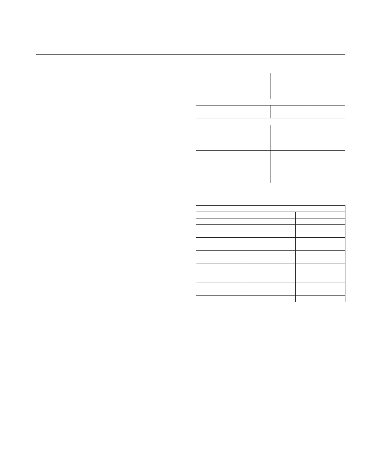
Minimum/Maximum Temperatures
Model
All Ice Machine Head Sections
All Remote Condensers
QuietQube Condensing Units
ICVD0695 - ICVD0696
ICVD1195 - ICVD1196
ICVD2095 - ICVD2196
ICVD0895 - ICVD0896
ICVD0996
ICVD1095 - ICVD1096
ICVD1495 - ICVD1496
ICVD1895 - ICVD1896
Minimum Air
Temperature
2°C
35°F
-29°C
-20°F
-29°C
-20°F
-29°C
-20°F
Maximum Air
Temperature
43°C
110°F
49°C
120°F
49°C
120°F
54°C
130°F
Ice Machine Heat of Rejection
Ice Machine Heat of Rejection
Series Air Conditioning Peak
I0300 4600 5450
I0320 3800 6000
I0450 5400 6300
I0500 6100 6900
I0520 5400 6300
I0600 9000 13900
I0850 13000 16000
I0906 13000 16000
I1000 16250 18600
I1200 20700 24500
I1400 23500 27000
I1800 31000 36000
I3300 45000 51000
Use this information when:
• Sizing air conditioning equipment where self-contained
air-cooled ice machines are installed.
• Determining the load on a cooling tower – Use the peak
figure for sizing the load.
Part Number: 000013325 Rev 02 6/17 9
Page 10
Installation Section 2
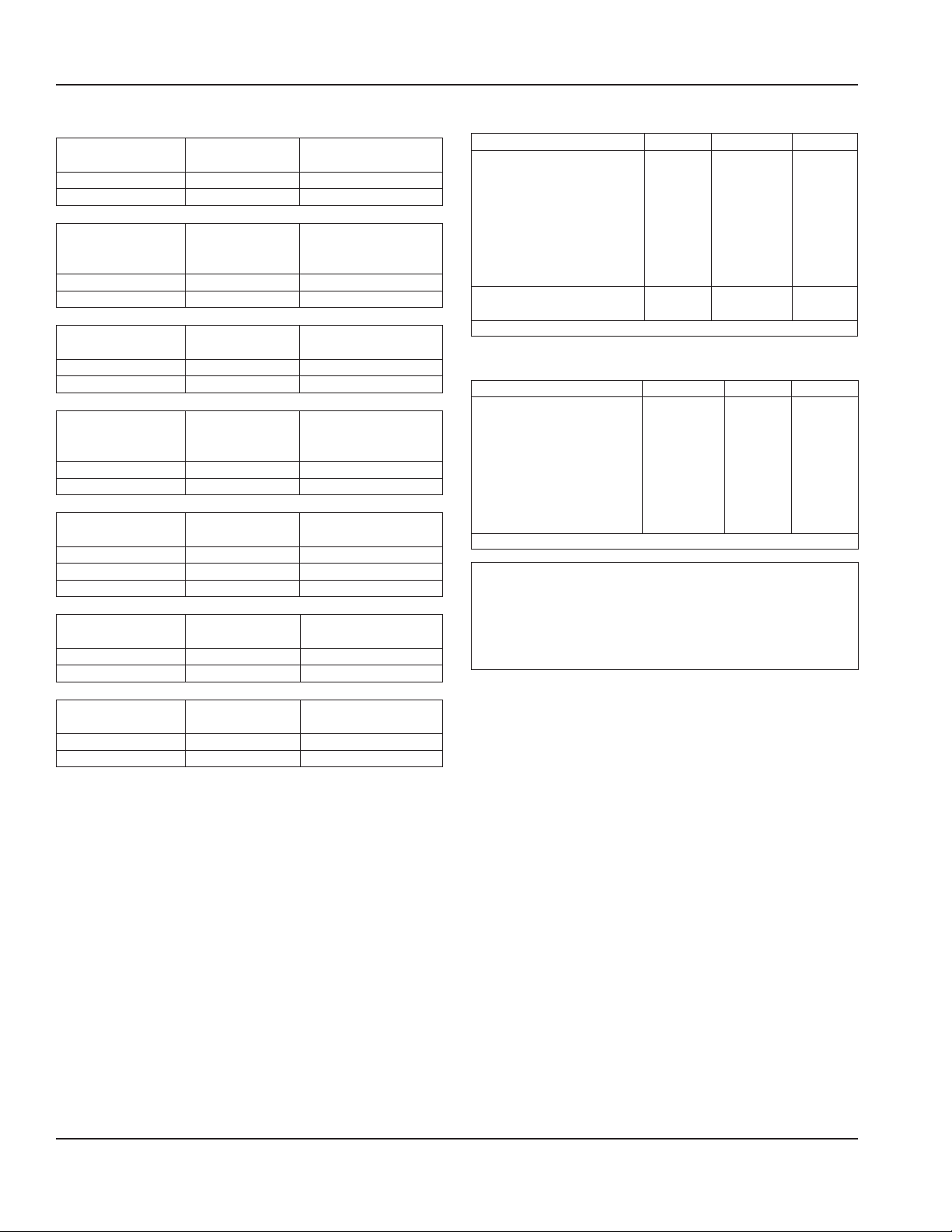
Clearance Requirements
I0300
Top/Sides 40 cm (16") 20 cm (8")
Back 13 cm (5") 13 cm (5")
I0450/I0500/ I0600/
I0850/I0900/I1000/
I1100
Top/Sides 20 cm (8") 20 cm (8")
Back 13 cm (5") 13 cm (5")
I0320/I0520
Top/Sides 31 cm (12") 20 cm (8")
Back 13 cm (5") 13 cm (5")
I0500
230/50/1 Tropical
Rating
Top 61 cm (24")
Sides/Back 31 cm (12")
I1200
Top 20 cm (8") 20 cm (8")
Sides 31 cm (12") 20 cm (8")
Back 13 cm (5") 13 cm (5")
I1400/I1800
Top/Sides 61 cm (24") 20 cm (8")
Back 31 cm (12") 13 cm (5")
Self-Contained
Air-Cooled
Self-Contained
Air-Cooled
Self-Contained
Air-Cooled
Self-Contained
Air-Cooled
Self-Contained
Air-Cooled
Self-Contained
Air-Cooled
Remote Condenser
Remote Condenser
Remote Condenser
Self-Contained
Water-Cooled
Water-Cooled or
Self-Contained
Water-Cooled
N/A
Water-Cooled or
Water-Cooled or
QuietQube Model Clearance Requirements
Model Top Back Sides
I0600C - I0686C
I0870C - I0876C
I0976C
I1070C - I1076C
I1176C
I1470C - I1476C
I1870C - I1876C
I2170C - I2176C
IB0690C - IB0890C - IB0896
IB1090C - IB1096
** 61 cm (24") is recommended on top/sides for servicing
13 cm
(5")
5 cm**
(2")
13 cm
(5")
13 cm
(5")
13 cm
20 cm**
Condensing Unit Clearance Requirements
Model Top/Sides Back Front
ICVD0695 - ICVD0696
ICVD0895 - ICVD0896
ICVD0996
ICVD1095 - ICVD1096
ICVD1195- ICVD1196
ICVD1495 - ICVD1496
ICVD1895 - ICVD1896
ICVD2095 - ICVD2096
* 61 cm (24") is recommended on top/sides for servicing
Caution
,
0 cm*
(0")
122 cm
(48")
122 cm
(48")
The ice machine must be protected if it will be subjected
to temperatures below 0°C (32°F). Failure caused by
exposure to freezing temperatures is not covered by the
warranty.
(5")
(8")
I3300
Top/Sides 20 cm (8")
Back 61 cm (24")
Self-Contained
Water-Cooled
N/A
NOTE: Top air discharge kits require the same clearance
requirements as the comparable self-contained air-cooled
model.
10 Part Number: 000013325 Rev 02 6/17
Page 11

Section 2 Installation
Bin Installation
NOTE: When using casters, the units must be tethered or
secured to comply with all applicable codes. Swivel casters
must be mounted on the front and rigid casters must be
mounted on the rear. Lock the front casters after installation
is complete.
1. Remove threaded plug from drain fitting.
2. Screw the leveling legs onto the bottom of the bin.
3. Screw the foot of each leg in as far as possible.
4. Move the bin into its final position.
5. Level the bin to assure that the bin door closes and seals
properly. Use a level on top of the bin. Turn the base of
each foot as necessary to level the bin.
6. Inspect bin gasket prior to ice machine installation.
(Manitowoc bins come with a closed cell foam gasket
installed along the top surface of the bin.)
7. Remove all panels from ice machine before lifting and
installing on bin. Remove both front panels, top cover,
left and right side panels.
Air Baffle
Self-Contained Air-cooled Only
The air-cooled baffle prevents condenser air from
recirculating. To install:
1. Loosen the back panel screws next to the condenser.
2. Align the keyhole slots in the air baffle with the screw
holes and slide the baffle down to lock in place.
Part Number: 000013325 Rev 02 6/17 11
Page 12

Installation Section 2
Electrical Requirements
All electrical work, including wire routing and grounding,
must conform to local, state and national electrical codes.
The following precautions must be observed:
• The ice machine must be grounded.
• A separate fuse/circuit breaker (dedicated circuit)
must be provided for each ice machine head section,
condenser or condensing unit.
• A qualified electrician must determine proper wire size
dependent upon location, materials used and length of
run (minimum circuit ampacity can be used to help select
the wire size).
Warning
n
All wiring must conform to local, state and national codes.
Voltage
The maximum allowable voltage variation is +10% / -5% of
the rated voltage at ice machine start-up (when the electrical
load is highest).
Warning
n
The ice machine must be grounded in accordance with
national and local electrical codes.
Fuse/Circuit Breaker
A separate electrical disconnect, which disconnects all poles
and has 3 mm (3/16") contact separation, must be provided
for fixed wiring. Circuit breakers must be H.A.C.R. rated in
USA.
Minimum Circuit Ampacity
The minimum circuit ampacity is used to help select the wire
size of the electrical supply. (Minimum circuit ampacity is not
the ice machine’s running amp load.)
The wire size (or gauge) also depends on location, materials
used, length of run, etc., so it must be determined by a
qualified electrician.
Ground Fault Circuit Interrupter
We do not recommend the use of a GFCI/GFI circuit
protection with our equipment. If a GFCI/GFI is required by
code, use a GFCI/GFI breaker rather than an outlet, which is
more prone to intermittent nuisance trips than panel circuit
breakers.
Important
3-Phase Scroll Compressors Only - Verify the direction
of rotation is correct on the 3-phase scroll compressor.
The ice machine will have high suction pressure, low
discharge pressure and will be noticeably loud. Reverse
any two incoming power leads to reverse rotation.
12 Part Number: 000013325 Rev 02 6/17
Page 13
Section 2 Installation
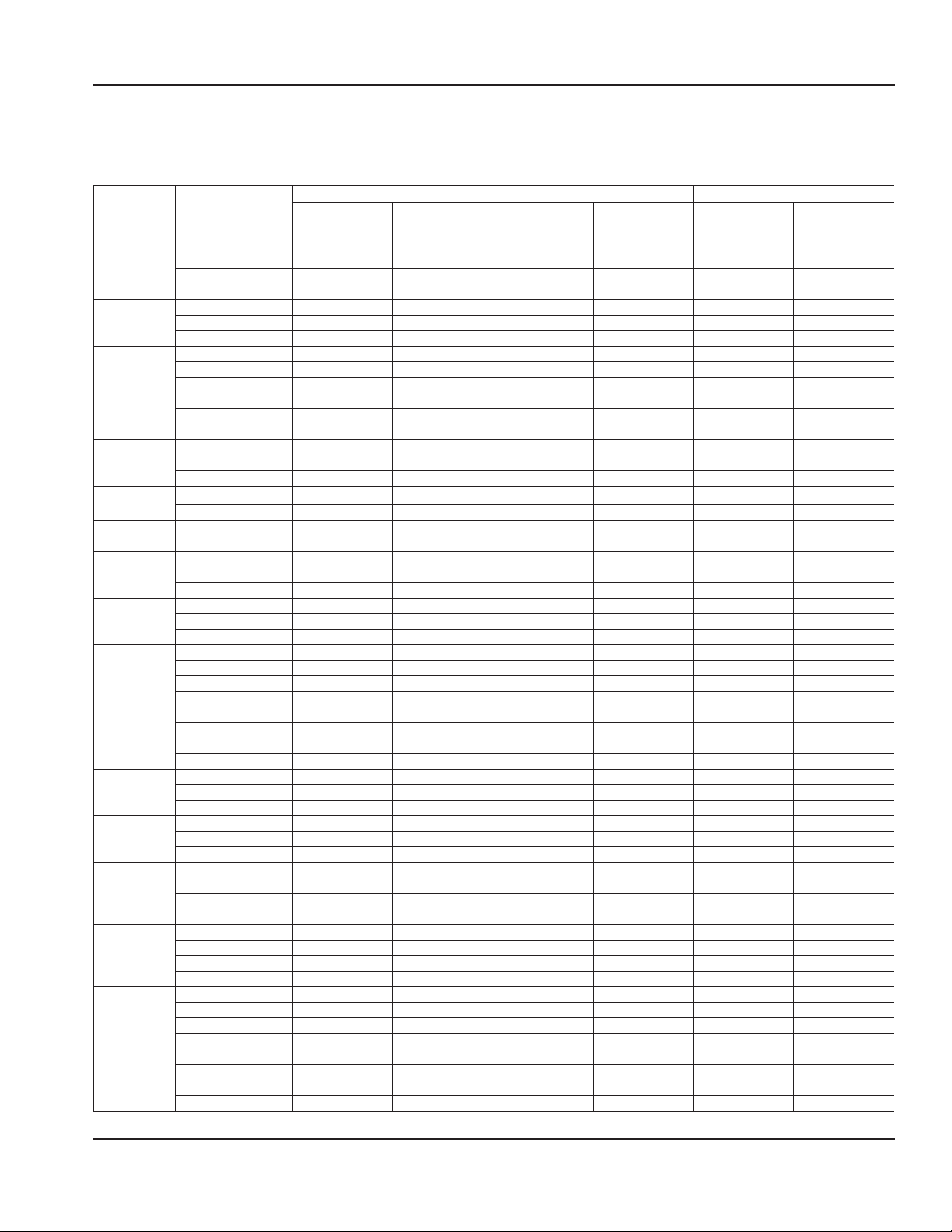
Maximum Breaker Size & Minimum Circuit Amperage Chart
NOTE: Due to continuous product improvements, this information is for reference only. Please refer to the ice machine data
plate to verify electrical data. Data plate information overrides information listed on this page.
Air-Cooled Water-Cooled Remote
Ice Machine
I0300
I0320
I0450
I0500
I0520
I0600
I0606
I0850
I0906
I1000
I1100
I1106
I1200
I1400
I1406
I1800
I1806
Voltage/Phase/
Cycle
115/1/60 15 10.8 15 10.0 N/A N/A
230/1/50 15 6.1 15 5.6 N/A N/A
230/1/60 15 6.1 15 5.7 N/A N/A
115/1/60 15 11.5 15 10.7 N/A N/A
208-230/1/60 15 6.0 15 5.6 N/A N/A
230/1/50 15 6.0 15 5.6 N/A N/A
115/1/60 20 13.2 20 12.5 N/A N/A
208-230/1/60 15 6.6 15 6.2 N/A N/A
230/1/50 15 7.1 15 6.8 N/A N/A
115/1/60 20 14.2 20 13.5 25 20.0
208-230/1/60 15 6.1 15 5.7 N/A N/A
230/1/50 15 7.1 15 6.8 15 6.7
115/1/60 20 14.4 20 13.5 N/A N/A
208-230/1/60 15 6.1 15 5.7 N/A N/A
230/1/50 15 7.1 15 6.8 N/A N/A
208-230/1/60 15 10.2 15 9.7 15 10.7
230/1/50 15 6.7 15 6.1 15 7.1
208-230/1/60 15 11.1 15 10.7 15 11.7
230/1/50 15 6.7 15 6.1 15 7.1
208-230/1/60 20 11.9 20 10.9 20 11.9
208-230/3/60 15 9.2 15 8.2 15 9.2
230/1/50 20 10.8 20 9.4 15 10.4
208-230/1/60 20 12.2 20 11.2 20 12.2
208-230/3/60 15 9.7 15 8.7 15 9.7
230/1/50 20 12.2 20 11.2 15 12.2
208-230/1/60 20 13.5 15 9.7 15 10.7
208-230/3/60 15 9.5 15 8.5 15 9.5
230/1/50 20 13.7 20 12.3 20 12.3
380-460/3/50-60 N/A N/A 15 4.5 N/A N/A
208-230/1/60 20 13.5 15 9.7 15 10.7
208-230/3/60 15 9.5 15 8.5 15 9.5
230/1/50 20 13.7 20 12.3 20 12.3
380-460/3/50-60 N/A N/A 15 4.5 N/A N/A
208-230/1/60 20 13.0 15 11.9 15 12.9
208-230/3/60 15 9.8 15 8.7 15 9.7
230/1/50 15 9.0 15 8.7 15 9.7
208-230/1/60 25 25.0 25 25.0 N/A N/A
208-230/3/60 20 16.0 20 16.0 N/A N/A
230/1/50 20 13.7 20 12.3 N/A N/A
208-230/1/60 30 18.3 30 16.9 30 17.9
208-230/3/60 20 13.2 20 11.8 20 12.8
230/1/50 30 15.9 30 15.9 30 16.9
380-460/3/50-60 N/A N/A 15 6.4 N/A N/A
208-230/1/60 30 15.9 30 14.3 30 14.9
208-230/3/60 20 12.3 20 11.3 20 12.3
230/1/50 30 15.8 30 14.2 30 16.9
380-460/3/50-60 N/A N/A 15 6.4 N/A N/A
208-230/1/60 40 23.8 40 22.4 40 23.4
208-230/3/60 25 15.4 25 14.0 25 15.0
230/1/50 30 18.3 30 16.9 40 17.9
380-460/3/50-60 N/A N/A 15 6.5 N/A N/A
208-230/1/60 40 23.8 40 22.4 40 23.4
208-230/3/60 25 15.4 25 14.0 25 15.0
230/1/50 30 18.3 30 16.9 30 17.9
380-460/3/50-60 N/A N/A 15 6.5 N/A N/A
Maximum
Fuse/Circuit
Breaker
Minimum
Circuit Amps
Maximum
Fuse/Circuit
Breaker
Minimum
Circuit Amps
Maximum
Fuse/Circuit
Breaker
Minimum
Circuit Amps
Part Number: 000013325 Rev 02 6/17 13
Page 14
Installation Section 2
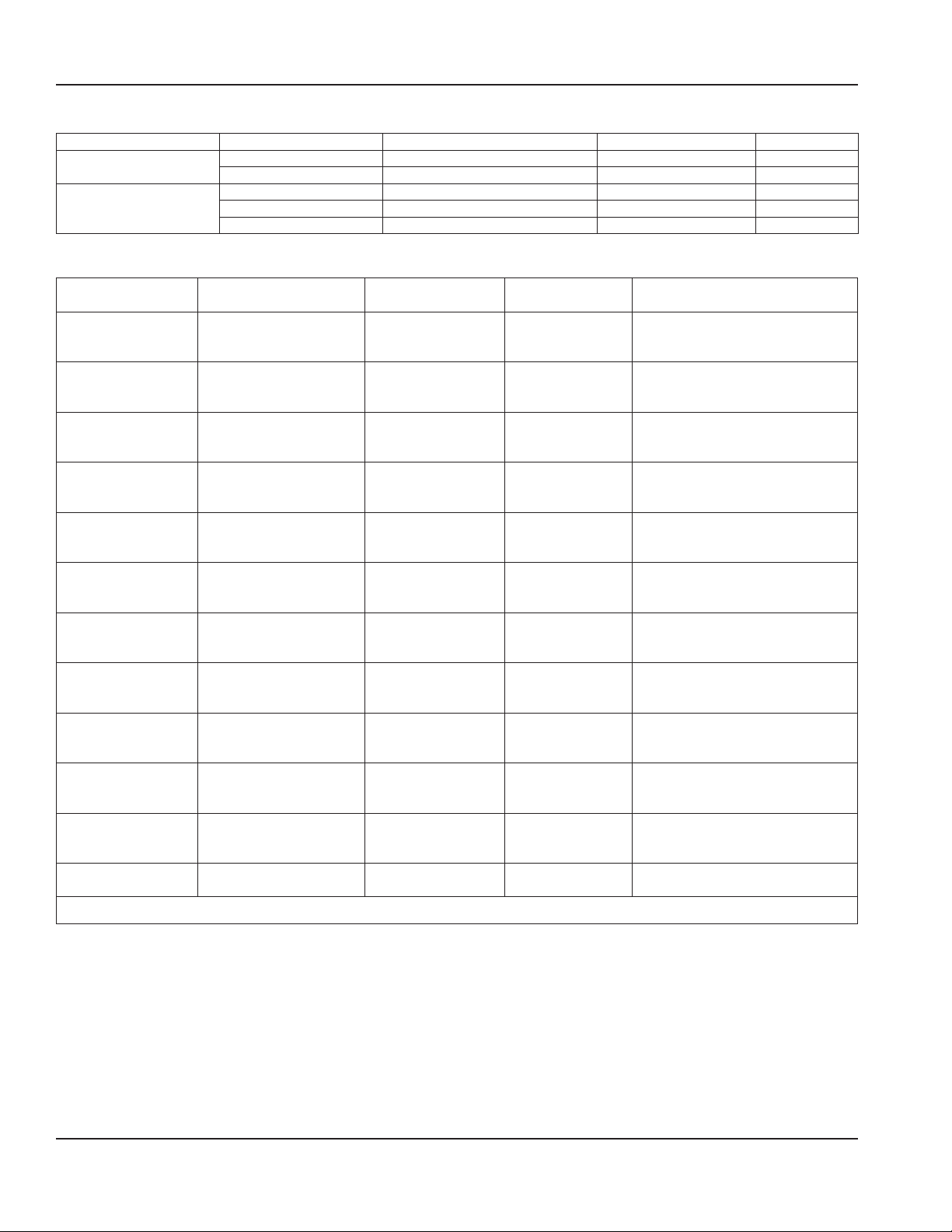
QuietQube Head Sections
Ice Machine Voltage/Phase/Cycle Maximum Fuse/Circuit Breaker Minimum Circuit Amps Total Amps
Ice Beverage Models
All Non IB QuietQube
Models
115/1/60 15 amp N/A 1.1
230/1/60 15 amp N/A 1.5
115/1/60 15 amp 1.1 N/A
208-230/1/60 15 amp 1.1 N/A
230/1/50 15 amp 1.5 N/A
ICVD Condensing Units
Condensing Unit Voltage/Phase/Cycle
208-230/1/60 15 amp 11.0 #12 Solid Copper Conductor
ICVD0695
ICVD0696
ICVD0895
ICVD0896
ICVD0996
ICVD1095
ICVD1195
ICVD1195 Bristol
Compressor
ICVD1495
ICVD1496
ICVD1895
ICVD2095 / ICVD2096
ICVD2095 & ICVD2096 Only - Verify the direction of the rotation is correct on the 3-phase scroll compressor. The ice machine will have high suction pressure, low discharge
pressure and will be noticeably loud. Reverse two incoming power leads to reverse rotation.
208-230/3/60 15 amp 7.5 #12 Solid Copper Conductor
230/1/50 15 amp 11.0 #12 Solid Copper Conductor
208-230/1/60 15 amp 11.6 #12 Solid Copper Conductor
208-230/3/60 15 amp 10.2 #12 Solid Copper Conductor
230/1/50 15 amp 10.2 #12 Solid Copper Conductor
208-230/1/60 20 amp 11.8 #10 Solid Copper Conductor
208-230/3/60 15 amp 9.1 #12 Solid Copper Conductor
230/1/50 20 amp 11.8 #10 Solid Copper Conductor
208-230/1/60 20 amp 11.8 #10 Solid Copper Conductor
208-230/3/60 15 amp 9.1 #12 Solid Copper Conductor
230/1/50 20 amp 11.8 #10 Solid Copper Conductor
208-230/1/60 20 amp 12.5 #10 Solid Copper Conductor
208-230/3/60 15 amp 9.5 #12 Solid Copper Conductor
230/1/50 20 amp 12.5 #10 Solid Copper Conductor
208-230/1/60 20 amp 15.0 #10 Solid Copper Conductor
208-230/3/60 15 amp 15.0 #12 Solid Copper Conductor
230/1/50 20 amp 15.0 #10 Solid Copper Conductor
208-230/1/60 25 amp 14.2 #8 Solid Copper Conductor
208-230/3/60 15 amp 9.5 #10 Solid Copper Conductor
230/1/50 35 amp 14.7 #8 Solid Copper Conductor
208-230/1/60 25 amp 14.5 #8 Solid Copper Conductor
208-230/3/60 15 amp 9.3 #10 Solid Copper Conductor
230/1/50 35 amp 14.3 #8 Solid Copper Conductor
208-230/1/60 20 amp 20.0 #10 Solid Copper Conductor
208-230/3/60 15 amp 15.0 #12 Solid Copper Conductor
230/1/50 20amp 20.0 #8 Solid Copper Conductor
208-230/1/60 20 amp 11.7 #10 Solid Copper Conductor
208-230/3/60 15 amp 8.9 #12 Solid Copper Conductor
230/1/50 20 amp 11.7* #8 Solid Copper Conductor
208-230/1/60 40 amp 25.0 #8 Solid Copper Conductor
208-230/3/60 25 amp 20.0 #10 Solid Copper Conductor
230/1/50 40 amp 25.0 #8 Solid Copper Conductor
208-230/1/60 50 amp 40.0 #6 Solid Copper Conductor
208-230/3/60 30 amp 30.0 #10 Solid Copper Conductor
Maximum Fuse/Circuit
Breaker
Minimum Circuit
Amps
Minimum Wire Size Required
by Manitowoc
14 Part Number: 000013325 Rev 02 6/17
Page 15
Section 2 Installation
V
C
LPC
HPC1
HPC2
Route Wire With Lineset
Minimum Requirements
- 5 Conductor Single Strand
- 18 AWG Plenum Rated
- UL Rated to 300 Volts
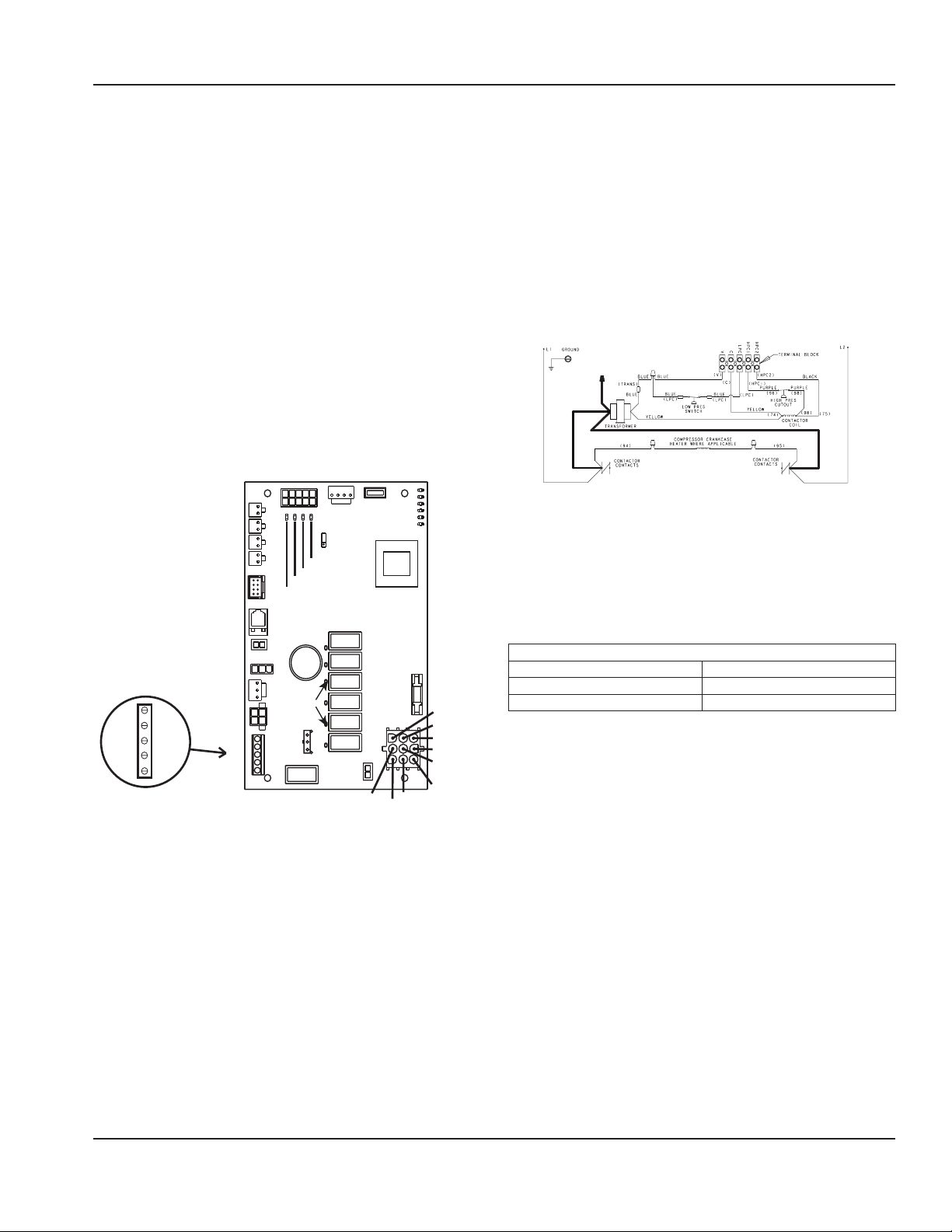
ICVD Interconnecting Wiring
Indigo QuietQube ice machines require interconnecting
low voltage wiring (included with Manitowoc line sets) to
energize the contactor coil and verify the LPCO & HPCO
are closed. This circuit also initiates a time delay whenever
the LPCO or HPCO open. Failure to properly wire the ICVD
condensing unit or ice machine head section will result in
a non-operational machine. Refer to the Indigo Technicians
Handbook for normal operation and diagnostics for the HPCO
& LPCO controls.
Connections on an RDI condensing unit are identical to the
ICVD connections.
Wire Specifications:
• 18 AWG - 5 Conductor, Single Strand
• Plenum Rated
• UL rated to 300 Volts
Bin
Bin Switches
iCVD Condensing Unit Terminal Strip
Connect Wiring To Matching Terminal
On Ice Machine Control Board
Thermistors
Display
RS485
Bin LED
LuminIce
Water
Level
Probe
AuCS
Remote CVD
HPC1
HPC2
Thermostat USB
T1
T2
T3
T4
V
Thickness
C
LPC
Dump Valve
Left Bin Switch Light
Right Bin Switch Light
Water Level Probe Light
Ice Thickness Probe Light
Compressor
Battery
Relay Lights
Ice
Probe
CVD
Contactor
RT Harvest
LT Harvest
Pump
Water
Dump
HPC
Water Inlet Valve
Left Harvest Valve
Dump Valve
Display Light
Micro Light
Clean Light
Harvest Light
SL-1 Light
SL-2 Light
Transformer
Fuse
Water Pump
Compressor
L1
L2
Not Used
Right Harvest Valve
ICVD Transformer Wiring
ICVD condensing units leave the factory with the L2
voltage leads for the transformer disconnected. Failure to
connect the transformer leads will result in a non-operable
condensing unit. Failure to correctly wire the transformer will
result in premature transformer failure.
1. Measure voltage with a voltmeter
2. Wire transformer to match voltage range
3. Cap unused lead to prevent shorting to ground.
RED =197V-219V
BLACK
197V-264V
ORANGE = 220V-264V
Remote Condenser Wiring
Interconnecting line voltage wiring is used to energize and
de-energize the condenser fan motor.
The remote condenser voltage matches the ice machine
head section voltage.
Interconnecting Wire Connections
Ice Machine Head Section Remote Condenser
F1 L1
F2 L2
Part Number: 000013325 Rev 02 6/17 15
Page 16

Installation Section 2
Condenser Water Inlet
Off
On / Off Mode
[ ]
!
Water Supply and Drain Line Sizing/Connections
• Local water conditions may require treatment of the
water to inhibit scale formation, filter sediment, and
Caution
,
Do not apply heat to water inlet valve or water drain
fittings. Heating will damage the nonmetallic connector.
Do not over tighten fittings. Two turns after hand tight is
the maximum.
remove chlorine odor and taste.
• Connect ice making water inlet to potable water only.
• Do not connect to hot water supply.
• Install a water shut-off valve.
• Insulate water and drain lines to prevent condensation.
Location Water Temperature Water Pressure Ice Machine Fitting
Ice Making Water Inlet
Ice Making Water Drain — — 1/2" Female Pipe Thread
Condenser Water Inlet
Condenser Water Drain — — 1/2" Female Pipe Thread
Bin Drain — — 3/4" Female Pipe Thread
Large Capacity Bin Drain 1" Female Pipe Thread
Min. = Minimum, Max. = Maximum
4,4°C (40°F) Min.
32°C (90°F) Max.
4,4°C (40°F) Min.
32°C (90°F) Max.
I0906 Marine Space Saver Models
This model allows water and electrical connections on the
top of the ice machine. The drain exits on the right side of
the ice machine.
Condenser Water Outlet
Potable Water Inlet
Electrical Inlet
140 kPa (20 psi) Min.
550 kPa (80 psi) Max.
140 kPa (20 psi) Min.
1030 kPa (150 psi) Max.
Cooling Tower Applications (Water-Cooled
Models)
A water cooling tower installation does not require
modification of the ice machine.
• Water pressure at the condenser cannot exceed 1034 kPa
(150 psig). A special order unit is available that allows
water pressure up to 2413 kPa (350 psig).
3/8" Female Pipe Thread
I0300 - I1000 = 3/8" Female Pipe Thread
I1106 - I1800 = 1/2" Female Pipe Thread
• Water entering the condenser must not exceed 32°C
(90°F).
Drain
• Water flow through the condenser must not exceed
19 liters (5 gallons) per minute.
• Allow for a pressure drop of 50 kPa (7 psi) between the
condenser water inlet and the outlet of the ice machine.
Air Gap
A greater than 1-inch air gap is built into the ice machine
• Water exiting the condenser must not exceed 43°C
(110°F).
for back-flow prevention. This air gap exceeds NSF 12
requirements for back-flow prevention.
Tubing Size up to Ice
Machine Fitting
10 mm (3/8") minimum
inside diameter
13 mm (1/2") minimum
inside diameter
13 mm (1/2") minimum
inside diameter
19 mm (3/4") minimum
inside diameter
25 mm (1") minimum
inside diameter
This Air Gap is Greater Than 1”
16 Part Number: 000013325 Rev 02 6/17
Page 17

Section 2 Installation
Drain Connections
Follow these guidelines when installing drain lines to prevent
drain water from flowing back into the ice machine and
storage bin:
• Drain lines must have a of run 2.5 cm per meter (1.5 inch
drop per 5 feet) and must not create traps.
• The floor drain must be large enough to accommodate
drainage from all drains.
• Run separate bin and ice machine drain lines. Insulate
them to prevent condensation.
• Vent the ice machine drain to the atmosphere.
• Drain termination must have an air gap that meets local
code.
Auxiliary Base Drain Installation
Two types of auxiliary drain are located in the ice machine
base to remove moisture in high humidity areas: With or
without a drain socket.
ICE MACHINES WITH AN AUXILIARY DRAIN SOCKET
1. Remove membrane in socket with a dowel or
screwdriver and proceed to step 3.
ICE MACHINES WITHOUT AN AUXILIARY DRAIN SOCKET
1. View the back of the ice machine base on the
compressor side, and locate the dimple.
2. Drill a 16 mm (5/8") hole using the dimple as a guide.
NOTE: Do not use a drill larger than 16 mm (5/8") or
irreparable damage will occur.
3. Route tubing to an open site drain:
• Use 1/2 inch CPVC tubing.
• Provide support for tubing.
• Apply a bead of silicone around the exterior of the
ice machine tubing and insert into ice machine base.
The silicone will secure the tubing and provide a
watertight seal.
Part Number: 000013325 Rev 02 6/17 17
Page 18

Installation Section 2
Remote Condenser and Remote Condensing Unit Refrigeration System Installation
Each ice machine head section ships from the factory with a refrigerant charge appropriate for the entire system operation. The
serial tag on the ice machine indicates the refrigerant charge.
QuietQube Models
Additional
QuietQube®
Ice Machine
I0680C
IB690C
IB0686C
IB0696C
I0870C
IB0890C
IB0890C
I0976C
I1070C ICVD1095 907 g - 2 lbs
IB1090C ICVD1195 907 g - 2 lbs
I1176C ICVD1195 907 g - 2 lbs
I1470C ICVD1495 RC-25
I1476C ICVD1495 907 g - 2 lbs
I1870C ICVD1895 907 g - 2 lbs
I2170C ICVD2095 RC-28
I2176C ICVD2096 1814 g - 4 lbs
I3070C ICVD3095 RC-29/39/59 1361 g - 3 lbs
*Line Set
RC 26/36/56
RC 25/35/55
RC 28/38/58
RC 29/39/59
Remote
Single Circuit
Condenser
ICVD0695
ICVD0696 680 g - 1.5 lbs
ICVD0895
ICVD0996 907 g - 2 lbs
Suction
Line
16 mm
5/8 inch
19 mm
3/4 inch
19 mm
3/4 inch
Two Lines
19 mm
3/4 inch
Liquid Line
3/8 inch
1/2 inch
5/8 inch
One Line
5/8 inch
n
Line Set*
10 mm
13 mm
16 mm
16 mm
Warning
RC-26
RC-36
RC-56
RC-35
RC-55
RC-38
RC-58
Minimum Insulation
13 mm (1/2") Suction Line
7 mm (1/4") Liquid Line
13 mm (1/2") Suction Line
7 mm (1/4") Liquid Line
13 mm (1/2") Suction Line
7 mm (1/4") Liquid Line
19 mm (3/4") Suction Line
7 mm (1/4") Liquid Line
Refrigerant
Charge for 15
to 30 Meter
Line Sets
(50’ - 100’)
680 g - 1.5 lbs
1814 g - 4 lbs
907 g - 2 lbs
907 g - 2 lbs
1814 g - 4 lbs
Thickness
Installation of a QuietQube® Condensing Unit may
require the use of special equipment for placement.
Trained and qualified personnel are required for proper
rigging and lifting. Holes are provided on the corners of
the condensing unit to allow the use of lifting shackles.
Manitowoc remote systems are only approved and
warranted as a complete new package. Warranty on the
refrigeration system will be void if a new ice machine
head section is connected to pre-existing (used) tubing or
condensing units or vice versa.
Remote Condenser Models
Remote
Condenser Ice
Machine
I0590N JC0495 680 g - 1.5 lbs
I0690N JC0895 680 g - 1.5 lbs
I0890N JC0895 907 g - 2 lbs
I0996N JC0995 907 g - 2 lbs
I1090N
I1196N
I1490N JC1395 907 g - 2 lbs
I1890N JC1395 907 g - 2 lbs
Line Set Discharge Line Liquid Line Model
RT 20/35/50 12.7 mm
RL 20/35/50 12.7 mm
Potential Personal Injury Situation
The ice machine head section contains the refrigerant
charge. Installation and brazing of the line sets must
be performed by a properly trained and EPA certified
refrigeration technician aware of the dangers of dealing
with refrigerant charged equipment.
Important
Additional Amount of
Remote
Condenser
JC0995 907 g - 2 lbs
1/2 inch
1/2 inch
n
Refrigerant to Be Added to
Nameplate Charge for 15 to 30
Meter Line Sets (50’-100’)
7.9 mm
5/16 inch
9.5 mm
3/8 inch
Warning
I0590/I0690
I0890/I0996/
I1090/I1196
I1490/I1890
18 Part Number: 000013325 Rev 02 6/17
Page 19

Section 2 Installation
H
H
D
H
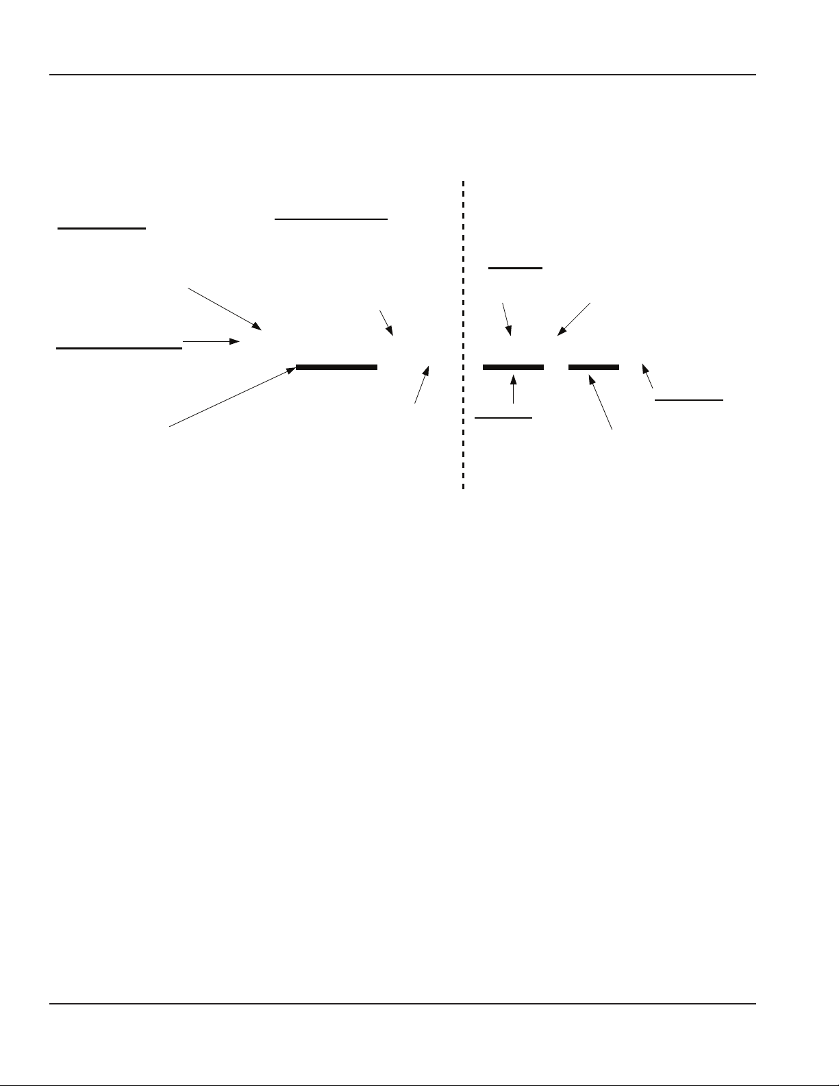
CALCULATING REMOTE CONDENSER & REMOTE CONDENSING UNIT INSTALLATION DISTANCES
Line Set Length
The maximum tubing length is 30 meters (100 feet).
Line Set Rise/Drop
1. Insert the measured rise into the formula below.
Multiply by 1.7 to get the calculated rise.
2. Insert the measured drop into the formula below.
Multiply by 6.6 to get the calculated drop.
The maximum rise is 10.7 meters (35 feet).
3. Insert the measured horizontal distance into the
The maximum drop is 4.5 meters (15 feet).
Caution
,
If a line set has a rise followed by a drop, another rise
cannot be made. Likewise, if a line set has a drop followed
by a rise, another drop cannot be made.
formula below. No calculation is necessary.
4. Add together the calculated rise, calculated drop, and
horizontal distance to get the total calculated distance.
If this total exceeds 45 meters (150 feet), move the
condenser/condensing unit to a new location and
perform the calculations again.
Calculated Line Set Distance
The maximum calculated distance is 45 meters (150 feet).
Line set rises, drops, horizontal runs (or combinations
of these) in excess of the stated maximums will exceed
compressor start-up and design limits. This will cause poor oil
return to the compressor. Make the following calculations to
make sure the line set layout is within specifications.
Maximum Line Set Distance Formula
Step 1. Measured Rise (R) 10.7 meters (35 feet) Maximum ______ x 1.7 = _______ Calculated Rise
Step 2. Measured Drop (D) 4.5 meters (15 feet) Maximum ______ x 6.6 = _______ Calculated Drop
Step 3. Measured Horizontal Distance (H) 30 meters (100 feet) Maximum _______ Horizontal Distance
Step 4. Total Calculated Distance 45 meters (150 feet) Maximum _______ Total Calculated Distance
R
R
SV1196
Combination of a Rise and a Horizontal
Run
Part Number: 000013325 Rev 02 6/17 19
Combination of a Drop and a Horizontal
Run
SV1195
Combination of a Rise, a Drop and a
Horizontal Run
D
SV1194
Page 20

Installation Section 2
Caution
,
The refrigeration system warranty will not apply if the
Manitowoc Ice Machine and Manitowoc ICVD Condensing
Unit are not installed according to specifications. This
warranty also will not apply if the refrigeration system is
modified with a condenser, heat reclaim device, or other
parts or assemblies not manufactured by Manitowoc.
10 METER (30
FEET) MAX.
DISTANCE
30 METER (100 FEET)
MAX. LINESET LENGTH
Step 1 Secure the Condenser.
Through-holes are provided to secure the condenser to a
curb, rack or wooden timber.
n
Warning
QUIETQUBE MODELS ONLY: WITH
MORE THAN 6 METER (20 FEET) RISE,
S-TRAP KIT IS REQUIRED
The ice machine head section contains refrigerant charge.
The ice machine head section contains refrigeration
valves that must remain closed until proper installation of
the line sets is completed.
Warning
n
Electrical power to the ice machine head section,
condensing unit or condenser must be disconnected
before proceeding.
Manitowoc S-Trap Kit
Model
I0680C IB0686C IB690C
I0686C I0696C I0870C
I0876C IB890C I0976C
I1070C I1076C IB1090C
IB1096C I1176C
I1470C I1476C I1870C
I1876C I2170C I2176C
S-Trap Kit
Number
K00172
K00166
Tubing Size
16 mm
(5/8 inch)
19 mm
(3/4 inch)
Step 2 Route the Refrigeration Tubing.
Route the refrigeration tubing between the ice machine head
section and the condenser or ICVD® condensing unit.
• Maximum lineset exposed on rooftop is 25% of total line
set length.
• A qualified person must perform all roof penetrations.
QuietQube Models Only
• A suction line oil trap is required when rise is more than 6
meters (20 feet).
• Only one trap is allowed in the lineset.
• Shorten the lineset as required, do not coil lineset.
20 Part Number: 000013325 Rev 02 6/17
Page 21

Section 2 Installation
Step 3 Connect the Line Set.
Remote Condensers Only
In most cases, by routing the line set properly, shortening
will not be necessary. When shortening or lengthening is
required, do so before connecting the line set to the ice
machine or the remote condenser. This prevents the loss of
refrigerant in the ice machine or condenser.
The quick connect fittings on the line sets are equipped with
access valves. Use these valves to recover any vapor charge
from the line set. When lengthening or shortening lines,
follow good refrigeration practices, purge with nitrogen
and insulate all tubing. Do not change the tube sizes.
Evacuate the lines and place about 145 grams (5 oz) of vapor
refrigerant charge in each line.
1. Remove the dust caps from the line set, condenser and
ice machine.
2. Apply refrigeration oil to the threads on the quickdisconnect couplers before connecting them to the
condenser.
3. Carefully thread the female fitting to the condenser or
ice machine by hand, then tighten the couplings with a
wrench until they bottom out.
4. Turn an additional quarter turn to ensure proper brassto-brass seating. Torque to the following specifications:
Liquid Line Discharge Line
13.5-16.2 N•m 47.5-61.0 N•m
QuietQube Models Only
• Maximum amount of time the refrigeration system can
be exposed to the atmosphere is 15 minutes.
• Purge line set with dry nitrogen while brazing.
• Shutoff valves for the line set on the ice machine must
remain closed and be protected from heat during brazing.
• The condensing unit ships with a 50/50 mixture of
nitrogen/helium.
VALVES MUST REMAIN
CLOSED AND BE
PROTECTED FROM HEAT
WHEN BRAZING (WRAP
WITH WET RAG)
SUCTION
LINE
LIQUID
LINE
5. Check all fittings and valve caps for leaks and reinstall
and tighten caps.
6. The receiver service valve is closed during shipment and
must be opened before starting the ice machine.
A. Remove the receiver service valve cap.
B. Backseat (open) the valve.
C. Reinstall the cap and panels.
7. Interconnecting line voltage wiring is used to energize
and de-energize the condenser fan motor. The remote
condenser voltage matches the ice machine head
section voltage.
Interconnecting Wire Connections
Ice Machine Head Section Remote Condenser
F1 L1
F2 L2
Installation is finished for remote condenser models. Proceed
to page 25 for start-up procedure.
MINIMIZE
REFRIGERATION SYSTEM
EXPOSURE TO ATMOSPHERE (15
MINUTES MAXIMUM)
Part Number: 000013325 Rev 02 6/17 21
Page 22

Installation Section 2
Step 4 Pressure Test and Evacuate Line Set and ICVD
Condensing Unit.
• Shutoff valves for the line set must remain closed until
pressure testing and evacuation are complete.
• Valve core removal tools that allow for removal and
installation of the valve cores without removing hoses for
the manifold gauge set are recommended to decrease
the evacuation time.
• Pressure test at 1000 kPa (150 psi) for a minimum of 15
minutes.
• Minimum evacuation level is 500 microns.
Pressure test the line sets and ICVD Condensing Unit with
1000 kPa (150 psi) of dry nitrogen. Add nitrogen at the
shutoff valves for the line set located at the back of the ice
machine head section or from the access valves located
in the ICVD Condensing Unit. Complete the pressure test,
verify no leaks are present and remove the nitrogen from the
system before connecting the vacuum pump.
ALTERNATE CONNECTIONS AT CONDENSING
UNIT SCHRADER VALVES
A retention valve is present in the compressor discharge line.
The retention valve requires evacuation connections at four
points.
Ice Machine Head Section
1. Low side shut off valve on the back of the ice machine
2. High side shut off valve on the back of the ice machine
ICVD Condensing Unit
3. Compressor Discharge Access Valve
4. Suction Filter Access Valve
Connection of a manifold gauge set (or a hose with core
depressors on both ends) between the suction-filter access
port and the compressor access valve (located between the
compressor and discharge line retention valve) is required.
CONNECT MANIFOLD GAUGE SET OR HOSE
RETENTION VALVE
WITH CORE DEPRESSORS ON BOTH ENDS
CONDENSER
LINESET
CONNECTION
LOCATION
CONNECT VACUUM PUMP TO SHUTOFF
VALVES FOR THE LINE SET
22 Part Number: 000013325 Rev 02 6/17
Page 23

Section 2 Installation
Step 5 Open Valves for the Line Set.
You will not hear refrigerant flow when the valves are
opened. Refrigerant will not flow until the ice machine is
started and the solenoid valve opens.
• All valve caps must be reinstalled, tightened and leakchecked to assure no refrigerant leakage exists.
• Counterclockwise opens all valves:
Refer to chart and open the shutoff valves for the suction
and liquid lines the correct number of 360° turns.
Valve Tubing Size Number of Turns to Open
3/8" 6
1/2" 5/8" 3/4" 10
7/8" 14
USE ALLEN WRENCH TO OPEN (TURN
COUNTERCLOCKWISE) SHUTOFF
VALVES FOR THE LIQUID AND
SUCTION LINES
USE ALLEN WRENCH
TO OPEN (TURN
COUNTERCLOCKWISE)
SHUTOFF VALVES
FOR THE LIQUID AND
SUCTION LINES
I1470C/I1870C/I2170C
Caution
,
After opening suction and discharge valves, refrigerant
pressure will not be detected until the ice machine starts
a freeze cycle and the solenoid valves energize.
QuietQube Models
USE ALLEN WRENCH
TO OPEN (TURN
COUNTERCLOCKWISE)
SHUTOFF VALVES
FOR THE LIQUID AND
SUCTION LINES
Ice Beverage Models
Part Number: 000013325 Rev 02 6/17 23
Page 24

Installation Section 2
Step 6 Connect Wiring to Condensing Unit or Remote
Condenser and Ice Machine Head Section.
ICVD REMOTE CONDENSING UNIT
Attach wiring to terminal strip in control box of condensing
unit and control board in ice machine head section. Match
wire labels to connections see “ICVD Interconnecting Wiring”
on page 15 and “ICVD Transformer Wiring” on page 15.
REMOTE CONDENSER
The remote condenser voltage matches the ice machine
head section voltage see “Remote Condenser Wiring” on
page 15.
Step 7 Leak-Check the Refrigeration System.
A. Connect power to the ice machine head section - Do
not connect power to the ICVD condensing unit.
B. Press the power switch and energize the ice
machine for 60 seconds to equalize pressures.
C. Disconnect power to the ice machine head section.
D. Leak-check lineset connections, S trap and all
factory joints in head section and condensing unit.
E. Connect power to the ICVD condensing unit and
allow system to pump down.
Step 9 Insulation for the Suction Shutoff Valve
The pre-formed insulation for the suction shutoff valve is
located in the plastic bag taped to the water curtain.
Position Bin Thermostat Probe
Ice Beverage Models Only
The thermostat probe must be moved from the shipping
position to the ice-making position.
• The bin thermostat probe must be rotated down to
enable ice contact and proper operation.
• Verify probe wire does not interfere with the water
curtain.
• The control is preset and does not require programming.
1. Loosen thumbscrew securing probe.
2. Rotate the probe from horizontal to vertical position.
3. Tighten thumbscrew to secure probe.
Step 8 Insulation Requirements
• To prevent condensation, the entire suction line,
including the shutoff valve, must be insulated.
• All insulation must be airtight and sealed at both ends.
The following insulation requirements prevent condensation
at 32°C (90° F) ambient temperature and 90% relative
humidity. If higher humidity is expected, increase insulation
thickness:
Suction Line Liquid Line Min. Insulation Thickness
19 mm
3/4 inch
16 mm
5/8 inch
19 mm
3/4 inch
13 mm
1/2 inch
10 mm
3/8 inch
16 mm
5/8 inch
Suction Line - 13 mm (1/2 inch)
Liquid Line - 7 mm (1/4 inch)
Suction Line - 19 mm (3/4 inch)
Liquid Line - 7 mm (1/4 inch)
24 Part Number: 000013325 Rev 02 6/17
Page 25

Section 2 Installation
07 24 10
Starting the Ice Machine
All Manitowoc ice machines are factory-operated and
adjusted before shipment. Normally, new installations do not
require any adjustment.
Starting the ice machine and completing the Operational
Checks are the responsibilities of the owner/operator.
Adjustments and maintenance procedures outlined in this
manual are not covered by the warranty.
Set the date and time for your area and verify the control
board settings are correct for your location and application.
Warning
n
Do not operate equipment that has been misused,
abused, neglected, damaged, or altered/modified from
that of original manufactured specifications.
This appliance is not intended for use by persons
(including children) with reduced physical, sensory or
mental capabilities, or lack of experience and knowledge,
unless they have been given supervision concerning use
of the appliance by a person responsible for their safety.
Do not allow children to play with, clean or maintain this
appliance without proper supervision.
Important
Refrigeration compressors must be operated for a
minimum break-in period of 72 hours before full ice
production will be reached.
Set the Language, Time and Date
When the ice machine is installed, the correct time and date
needs to be set for its location.
1. Ensure that the ice machine’s power is on.
2. Press the Menu button.
3. Press the Down arrow until Set-Up is highlighted
[bracketed].
4. Press the Checkmark. The Set-Up menu will be displayed
and Language will be highlighted [bracketed]. The
default language is English.
5. Press the Checkmark. You can choose to view the
display in a language other than English by highlighting
your choice and pressing the Checkmark. Selecting one
language will deselect the others.
6. When the check reflects your preference, use the Down
arrow to navigate to Exit and press the Checkmark. The
display will return to the Set-Up menu.
7. Use the Down arrow to highlight Time & Date.
8. Press the Checkmark. The date will appear on the
first line of the display (Mo/Day/Yr) and the time will
appear on the second line (24 Hour). The month will be
underlined.
14:08
Exit >
9. Using the Up or Down arrow, adjust the month, if
necessary.
10. When the correct month appears, use the Right arrow to
move the underline to the day.
11. Using the Up or Down arrow, adjust the day, if necessary.
12. When the correct day appears, use the Right arrow to
move the underline to the year.
13. Using the Up or Down arrow, adjust the year, if
necessary.
14. When the correct year appears, press the Checkmark.
The underline will move down to the hour.
15. Using the Up or Down arrow, adjust the hour, if
necessary.
16. When the correct hour appears, use the Right arrow to
move the underline to minutes.
17. Using the Up or Down arrow, adjust the minutes, if
necessary.
18. When the correct minutes appear, press the Checkmark
twice.
For more details and instructions for changing ice machine
settings, see “Set-Up Menu” in Section 3 Operation.
Part Number: 000013325 Rev 02 6/17 25
Page 26

Installation Section 2
Remove Ice Thickness Probe Shipping Brackets
Remove and discard shipping brackets before starting the ice
machine.
Starting the Ice Machine
Step 1 Refer to cleaning and sanitizing procedure and
sanitize the ice machine and bin before placing in operation.
Step 2 Press the power button to start ice-making.
NOTE: The water curtain/ice damper(s) must be in place on
the evaporator before the ice machine will start.
Refer to the sequence of operation in Section 3 for further
operational details.
Step 3 Observe a freeze and harvest cycle, then perform
an ice thickness check.
MINIMUM/MAXIMUM SLAB WEIGHT
Adjust ice thickness to meet chart specifications.
Model
i300
i320 - i450 - i520
i500 - i680 - i686 i690 - i696
i600 - i606
i850 - i870 - i890 - i976
i906 -i1000 - i1006 - i1070
i1200
i1090
i1400 - i1406
i1470
i1800
i1870 - i2170 - i2176
Minimum
Ice Weight Per
Cycle
lbs
Grams
2.40 lbs
1089 grams
3.40 lbs
1542 grams
4.60 lbs
2087 grams
4.12 lbs
1869 grams
5.75 lbs
2608 grams
6.2 lbs
2812 grams
7.50 lbs
3402 grams
7.50 lbs
3402 grams
10.25 lbs
4649 grams
12.0 lbs
5443 grams
13.20 lbs
5987 grams
15.5 lbs
7031 grams
Maximum
Ice Weight Per
Cycle
lbs
Grams
2.80 lbs
1270 grams
3.90 lbs
1769 grams
5.20 lbs
2359 grams
4.75 lbs
2155 grams
6.50 lbs
2948 grams
7.2 lbs
3266 grams
8.20 lbs
3719 grams
8.50 lbs
3856 grams
11.50 lbs
5216 grams
14.0 lbs
6350 grams
14.80 lbs
6713 grams
16.75 lbs
7598 grams
Ice Thickness Check
After a harvest cycle, inspect the ice cubes in the ice storage
bin. The ice thickness probe is factory-set to maintain the ice
bridge thickness at 3 mm (1/8").
NOTE: Make sure the water curtain is in place when
performing this check. It prevents water from splashing out
of the water trough.
1. Inspect the bridge connecting the cubes. It should be
about 3 mm (1/8") thick.
2. If adjustment is necessary, turn the ice thickness probe
adjustment screw clockwise to increase bridge thickness,
counterclockwise to decrease bridge thickness. Set at
7 mm (9/32") gap between ice thickness probe and
evaporator as starting point, then adjust to achieve a 3
mm (1/8") bridge thickness.
NOTE: Turning the adjustment one-third of a turn will change
the ice thickness about 1.5 mm (1/16").
ADJUSTING SCREW
3 mm (1/8")
ICE BRIDGE THICKNESS
PLACE 7 mm (9/32") DRILL BIT HERE
BETWEEN PROBE AND EVAPORATOR
TO SET INITIAL GAP
Ice Thickness Check
Make sure the ice thickness probe wire doesn’t restrict movement
of the probe.
26 Part Number: 000013325 Rev 02 6/17
Page 27

Section 3
Operation
Power Button
LCD Display
Menu
Button
Manitowoc
Off
On / Off Mode
!
[ ]
Left Arrow Up and Down Arrows
Cleaning Button
Status
Lines
}
Alert/Message Line
Checkmark
Right Arrow
Control Panel Features
The Indigo™ control panel offers a series of pressuresensitive buttons and a four-line, interactive display panel.
BUTTONS
Power Button: Powers the ice machine when in the On/
Off Mode. The ice machine can also be programmed to
automatically power on and off in two Energy Saver modes.
Cleaning Button: Initiates a cleaning cycle. Refer to Section 4
for details.
Menu Button: Moves the display from the Home Screen,
where ice machine status, alerts and messages are viewed,
to the Main Menu, where machine information and its event
log can be accessed, machine and Energy Saver settings can
be adjusted, and service issues can be addressed.
Left and Right Arrows: The Left arrow moves the display
to the previous screen, allowing the user to “back out” of
programming. Both the Left and Right arrows will move the
cursor (underline) within a line of settings. NOTE: The Right
arrow can also be used on many screens interchangeably
with the Checkmark to make a selection.
Up and Down Arrows: Move the highlight [brackets] up one
line or down one line.
Checkmark: Makes a selection and/or moves to the next
screen (or line).
DISPLAY PANEL
The LCD display panel is 16 characters wide and four lines
deep. During ice machine operation and cleaning cycles,
the Home screen’s top three lines provide valuable status
information and the fourth line shows alerts and messages.
In programming, four lines of the current menu are displayed
and highlights, arrows, cursor and selections inform the user
of available actions.
Part Number: 000013325 Rev 02 6/17 27
Page 28
Operation Section 3
Indigo™ Models -
Menu Navigation Overview
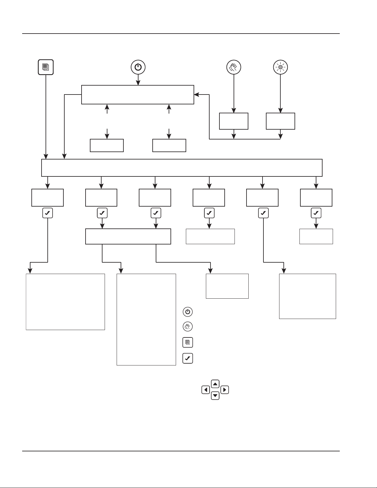
Overview of Menu Navigation
Menu Button Cleaning ButtonON/OFF Button Timer Initiated
Home Screen
Machine
Info
90/70 Capacity
Model Number
Ice Machine Head Serial Number
Condenser Serial Number
Warranty
Install Date
Manufacture Date
Main Software Version
Display Software Version
Exit
Energy
Saver
When
Message
Present
Main Menu
Defaults
Defaults
Exit
Ice Program
Water Miser
Statistics
Exit
Press to power ON/OFF
Press to access cleaning function
Press to access Main Menu
Press to select menu/sub-menu option
When
Alert
Present
Alerts Messages
Set-up
Password Entry
(Optional)
Language
Time/Date
Time Config
Units
Ice Clarity
LCD Brightness
Password On
Edit Password
Clean Minder
AuCS Run Time
Air Filter
Water Filter
LUMINICE
Ice Bin Sensor
USB Setup
Gateway Setup
Exit
Clean
Function
Service
AuCS Clean
Function
Data History
Real Time Data
Diagnostics
Manual Harvest
Replace Control Board
USB Setup
Event Log
Exit
EXIT
Return to
Home Screen
Navigate Menus
28 Part Number: 000013325 Rev 02 6/17
Page 29

Section 3 Operation
[Time & Date >]
▼
▼
07 24 10
[Mo/Day/Yr ( )]
▼
▼
[ ]
!
Display Panel Navigation
Time Config >
Units >
Highlights: Brackets indicate if a line on the screen is
“highlighted” or actionable. Move the brackets from line to
line using the Down or Up arrow. Move the brackets down
from the fourth line to view more of the menu displayed.
Arrows: Two kinds of arrows give cues to additional
information. “>” symbols show that another screen
is available by pressing the Checkmark while a line is
highlighted. “” and “” symbols indicate the limits of the
screen viewed. NOTE: Another cue to the length of a menu
screen is that Exit is the last item.
14:08
Exit >
Cursor: A cursor (underline) is used within lines where actual
settings can be adjusted. In these screens, use the Up and
Down arrows to make changes to the value underlined. Move
the cursor from digit to digit using the Right and Left arrows.
Use the Checkmark to move the cursor down one line. Exit
and re-enter the screen to start again at the top.
Alerts and Messages
When messages and alerts exist, they will be highlighted and
can be selected with the Checkmark. Alerts are shown on
the left side - Alerts are conditions that may cause the ice
machine to stop in the near future. Alerts displayed will have
priority over messages.
Messages are shown on the right side and appear as an
envelope - They are reminders such as clean your air
condenser filter, change your water filter, etc.
Off
On / Off Mode
For example, if alerts are appearing in the fourth line of the
display:
1. Press Checkmark. A list of alerts will appear in the
display.
2. Choose the alert you wish to address by moving the
highlight brackets with the Down arrow.
3. Press Checkmark again. A screen appears with a line that
can be selected for clearing the alert, a line for accessing
a list of possible causes and a line for accessing service
information.
4. Return to the Home screen by pressing the Left arrow
until it appears.
Machine Info
Day/Mo/Yr ( )
12 Hour ( )
24 Hour ( )
Selections: When parentheses ( ) appear, they indicate a
selection is available by pressing the Checkmark while the
line is highlighted. If the choice is exclusive, selecting it with
the Checkmark will uncheck another selection. That is, in
the above Time Config example, selecting Day/Mo/Yr will
deselect Mo/Day/Yr.
Part Number: 000013325 Rev 02 6/17 29
Set-Up
Energy Saver
Fact Deflts
Service
Exit
Main Menu
Page 30

Operation Section 3
[
▲
Main Menu
From the Home screen, press the Menu button to enter
the Main menu, where you can choose to see machine
information, make setup changes, set the Energy Saver
mode, or enter the Service Menu.
MACHINE INFO MENU
From the Main menu, ensure that Machine Info is
highlighted and press the Checkmark to view a list including
capacity, model number, Ice Machine Head serial number,
condenser serial number, warranty, installation date, date
of manufacture and software versions. Use the Down
arrow to highlight an item and use the Checkmark to view
the information. Press the Left arrow to return to previous
screens.
PASSWORD ENTRY
A password is not required, although a password can
be turned on to prevent unauthorized control setting
modification. You can use the Factory Default Password
of “1234” or enter a four digit custom pin number of your
choosing.
To turn on the password feature use the following procedure.
1. Press the Menu button.
2. From the Main menu, use the Down arrow to highlight
Set-Up and press the Right arrow.
3. Use the Down arrow to highlight Password ON and press
the Right arrow.
4. Press the Right arrow again with Enter Passwrd
highlighted and an icon will flash.
5. Use the Up and Down arrows to enter the factory
password (1, 2, 3, 4). Enter the number 1 in the flashing
icon (first digit of the factory password).
6. Press the Right arrow to move to the next cell and use
the Up and Down arrows to add the number 2. Repeat
this process to add 3 and 4.
7. When the last number is entered press the Checkmark
button to save your entry.
Enter Passwrd
]
Exit >
To enter a four digit password of your choosing use the
following procedure.
1. Press the Menu button.
2. From the Main menu, use the Down arrow to highlight
Set-Up and press the Right arrow.
3. Use the Down arrow to select Edit Password and press
the Right arrow.
4. Using the Up and Down arrows, enter the first digit of
the factory password in the flashing icon.
5. Press the right arrow to move to the next cell and use
the Up and Down arrows to add the number 2. Repeat
this process to add 3 and 4.
6. When the last number is entered press the Checkmark
button.
7. Follow steps 4 and 5 and enter your 4 digit password.
8. When the last number is entered press the Checkmark
button to save your entry.
Reset Password to Factory Defaults
The password can be reset to the factory defaults when
required. The default factory password is 1234. To reset the
ice machine to factory defaults, use the following procedure.
1. Press the Menu button.
2. From the Main menu, use the Down arrow to highlight
Fact Deflts.
3. Press the Checkmark two times to reset the ice machine.
The display will return to the Set-Up menu and the
defaults listed below will be in effect. Refer to Set-Up
Menu to adjust settings.
Setting Default
Language English
Time & Date Central Time Zone
Time Config Month/Day/Year/24 Hour
Units Fahrenheit/Lbs/Gallons
Ice Clarity Off
LCD Bright Level 2
Password On/Off Off
Clean Minder Off
AuCS RunTime Off
Air Filter Off
Water Filter Off
LuminIce™ Replace Bulb
Reminder
Off
30 Part Number: 000013325 Rev 02 6/17
Page 31

Section 3 Operation
Set-Up
Time Configuration
Exit
[Mo/Day/Yr ( )]
▼
▼
SET-UP MENU
From the Main menu, use the Down arrow to navigate to SetUp and press the Checkmark. Select and customize machine
settings on this menu. Press the Left arrow to return to
previous screens.
Language
Time & Date
Units
Ice Clarity
LCD Bright
Password On
Edit Password
Clean Minder
AuCS RunTime
Air Filter
Water Filter
LUMINICE
Ice Bin Sensor
Language
1. From the Set-Up menu, use the Down arrow to highlight
Language.
2. Press the Checkmark. You can choose to view the
display in a language other than English by highlighting
your choice and pressing the Checkmark. Selecting one
language will deselect the others.
3. When the check reflects your preference, use the Down
arrow to navigate to Exit and press the Checkmark. The
display will return to the Set-Up menu.
Time & Date
Refer to Operational Checks, page 25 for step-by-step
instructions for setting the time and date.
Day/Mo/Yr ( )
12 Hour ( )
24 Hour ( )
Time Configuration
1. From the Set-Up menu, use the Down arrow to highlight
Time Config.
2. Press the Checkmark. On this screen, you can choose
whether the date will be displayed as Mo/Day/Yr or
Day/Mo/Yr by highlighting your choice and pressing the
Checkmark. Selecting one will deselect the other.
3. You can also choose whether the time will be displayed
as 12 Hour or 24 Hour by highlighting your choice and
pressing the Checkmark. Selecting one will deselect the
other.
4. When the two checks reflect your preference, use
the Down arrow to navigate to Exit and press the
Checkmark. The display will return to the Set-Up menu.
Part Number: 000013325 Rev 02 6/17 31
USB Setup
Set-Up Menu
Page 32

Operation Section 3
Units
1. From the Set-Up menu, use the Down arrow to highlight
Units.
2. Press the Checkmark. On this screen, you can choose
whether the ice machine will display measurements in
Celsius or Fahrenheit, kilograms or pounds, and gallons
or liters by highlighting your choice of each pair and
pressing the Checkmark. Selecting one of each pair will
deselect the other. Make sure to navigate with the Down
arrow to make all three choices.
3. When the three checks reflect your preferences, use
the Down arrow to navigate to Exit and press the
Checkmark. The display will return to the Set-Up menu.
Ice Clarity
In areas with poor potable water quality, the ice machine
makes cloudy ice. Setting Ice Clarity to ON will add additional
water during the freeze cycle to dilute the water that
contains a high content of dissolved solids in the water
trough. This feature decreases production and increases
water usage. A water filter is recommended to produce the
highest quality ice while maintaining the least expensive
mode of operation.
1. From the Set-Up menu, use the Down arrow to highlight
Ice Clarity.
2. Press the Checkmark. On this screen, you can choose
to turn the ice clarity feature ON or OFF by highlighting
your choice and pressing the Checkmark. Selecting one
will deselect the other.
3. When the check reflects your preference, use the Down
arrow to navigate to Exit and press the Checkmark. The
display will return to the Set-Up menu.
LCD Brightness
Here, the brightness of the LCD display can be adjusted.
1. From the Set-Up menu, use the Down arrow to highlight
LCD Bright.
2. Press the Checkmark. You will see one to four checkmark
symbols indicating the brightness levels of the display.
Level 1 is 1 checkmark, level 2 is 2 checkmarks, etc.
3. Use the Up and Down arrows to select your preference.
4. When the number of checkmark symbols reflects your
preference, press the Checkmark button. The display will
return to the Set-Up menu.
Password On
A password can be added to prevent unauthorized changes
to ice machine settings.
1. From the Set-Up menu, use the Down arrow to highlight
Password On.
2. Enter the password and press the Checkmark.
3. Press the Left arrow to return to previous screens and to
the Set-Up menu.
Edit Password
The password can be changed on this screen.
1. From the Set-Up menu, use the Down arrow to highlight
Edit Passwrd.
2. Press the Checkmark and confirm current password.
3. Enter new password and press the Checkmark.
4. Press the Left arrow to return to previous screens and to
the Set-Up menu.
32 Part Number: 000013325 Rev 02 6/17
Page 33

Section 3 Operation
Clean Minder
Clean Minder is a feature that displays a cleaning reminder at
a set time interval.
1. From the Set-Up menu, use the Down arrow to highlight
Clean Minder.
2. Press the Checkmark. On this screen, you can choose to
turn the reminder ON or OFF by highlighting your choice
and pressing the Checkmark. Selecting one will deselect
the other.
3. You can also choose the time interval from this screen by
highlighting Set Interval and pressing the Checkmark.
4. Press the Left arrow to return to previous screens and to
the Set-Up menu.
AuCS Runtime
Automatic Cleaning System (AuCS) is an optional accessory
and will perform a cleaning cycle at a set time interval.
1. From the Set-Up menu, use the Down arrow to highlight
AuCS RunTime.
2. Press the Checkmark. On this screen, you can choose to
turn the feature ON or OFF by highlighting your choice
and pressing the Checkmark. Selecting one will deselect
the other.
3. You can also choose the time interval from this screen by
highlighting Set Interval and pressing the Checkmark.
4. Press the Left arrow to return to previous screens and to
the Set-Up menu.
Air Filter
The ice machine has a feature that displays a clean air filter
reminder at a set time interval.
1. From the Set-Up menu, use the Down arrow to highlight
Air Filter.
2. Press the Checkmark. On this screen, you can choose to
turn the reminder to AUTO or OFF by highlighting your
choice and pressing the Checkmark. Selecting one will
deselect the other.
3. You can also choose the time interval from this screen by
highlighting Set Interval and pressing the Checkmark.
4. Press the Left arrow to return to previous screens and to
the Set-Up menu.
Water Filter
The ice machine has a feature that displays a replace water
filter reminder at a set time interval.
1. From the Set-Up menu, use the Down arrow to highlight
Water Filter.
2. Press the Checkmark. You can record the filter type on
this screen by highlighting Filter Type and pressing the
Checkmark.
3. After making your selection, press the Left arrow to
return to the previous screen.
4. On this screen, you can also choose to turn the reminder
to AUTO or OFF by highlighting your choice and pressing
the Checkmark. Selecting one will deselect the other.
5. You can further choose the time interval from this screen
by highlighting Set Interval and pressing the Checkmark.
6. Press the Left arrow to return to previous screens and to
the Set-Up menu.
Part Number: 000013325 Rev 02 6/17 33
Page 34
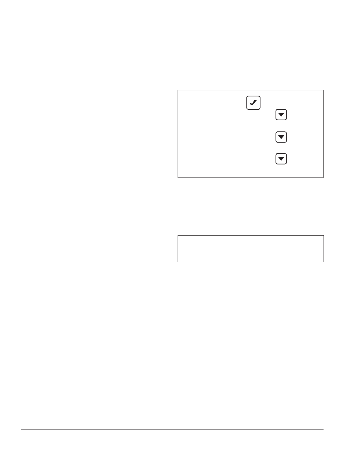
Operation Section 3
LuminIce® II Reminder
The LuminIce® growth inhibitor recirculates the air in the ice
machine foodzone over a UV bulb. This process will inhibit
the growth of common micro-organisms on all exposed
foodzone surfaces.
The LuminIce® II has a feature that displays a reminder to
change its bulb every 12 months.
1. From the Set-Up menu, use the Down arrow to highlight
LUMINICE.
2. Press the Checkmark. On this screen, you can choose to
turn the reminder to AUTO or OFF by highlighting your
choice and pressing the Checkmark. Selecting one will
deselect the other.
3. When the check reflects your preference, use the Down
arrow to navigate to Exit and press the Checkmark. The
display will return to the Set-Up menu.
USB Setup
Refer to “Upgrading Firmware with a Flash Drive” and
“Exporting Data to a Flash Drive” for more information on
this setting.
ENERGY SAVER MENU
From the Main menu, use the Down arrow to navigate to
Energy Saver and press the Checkmark. Set up an energy
saving ice program, enable the Water Miser and view usage
statistics from this menu. Press the Left arrow to return to
previous screens.
Energy Saver Ice Program
Water Miser
Statistics
Exit
Energy Saver Menu
Ice Program
To save energy and water, the ice machine can be
programmed to only power up during time periods that the
ice will be used or when the bin level is being depleted by
heavy use.
Important
Setting an ice program will take the ice machine out of
the On/Off Mode and the Power button will be disabled.
1. In the Energy Saver menu, ensure that Ice Program is
highlighted.
2. Press the Checkmark. On this screen, you can choose to
turn on the time program or the bin level program by
highlighting your choice and pressing the Checkmark.
Selecting one will deselect the other. If one of them is
selected and you wish to turn both off, highlight the
choice and press Checkmark again.
3. If neither of the programs is selected, highlighting Next
and pressing the Checkmark will simply return to the
top of this screen. If one of the programs is selected,
highlight Next and press the Checkmark to choose the
times or bin levels. NOTE: For details on how to use
the cursor for the time program, refer to “Display Panel
Navigation” in this section.
4. Select Exit to return to previous screens and again to the
Energy Saver menu.
34 Part Number: 000013325 Rev 02 6/17
Page 35

Section 3 Operation
Ice Bin Level Sensor
Ice bin sensor is an optional accessory that allows the ice
level in the bin to be set to one of three different levels. The
bin level can be set seasonally to match usage, which results
in lower energy costs and fresher ice.
1. In the Energy Saver menu, ensure that Ice Program is
highlighted and press checkmark.
2. Select Bin Level and press checkmark.
3. Select Settings and press checkmark.
4. On this screen you can choose to set the ice level to low,
medium or high by highlighting your choice and pressing
the Checkmark. Selecting one will deselect the other.
NOTE: On ice beverage models you must choose low for
the control to function. The ice beverage sensor has one
thermistor, while the bin level sensor has three.
5. Select - Exit, Save changes, Yes and then Done.
When the check reflects your preference, use the Down to
navigate to Exit and press the Checkmark. The display will
return to the Set-up menu.
Water Miser
Water Miser is a feature that reduces water usage by
eliminating flush cycles. Enabling this feature is only
recommended for systems with de-ionized or reverse
osmosis filtering.
1. From the Energy Saver menu, use the Down arrow to
highlight Water Miser.
2. Press the Checkmark. On this screen, you can choose
to turn the Water Miser ON or OFF by highlighting your
choice and pressing the Checkmark. Selecting one will
deselect the other.
3. Press the Left arrow to return to previous screens and to
the Energy Saver menu.
Statistics
1. From the Energy Saver menu, use the Down arrow to
highlight Statistics.
2. Press the Checkmark. Choose to view ice production,
potable water usage or energy usage statistics by
highlighting your choice and pressing the Checkmark.
3. Press the Left arrow to return to previous screens and to
the Energy Saver menu.
Factory Defaults
The entire setup can be reset to the factory defaults.
1. From the Set-Up menu, use the Down arrow to highlight
Fact Default.
2. Press the Checkmark two times to reset the ice machine.
The display will return to the Set-Up menu.
Part Number: 000013325 Rev 02 6/17 35
Page 36

Operation Section 3
Service Menu
From the Main menu, use the Down arrow to navigate to
Service and press the Checkmark. This menu is intended for
the use of trained service personnel.
Data History
Press the Checkmark with Data History highlighted to view
a list of eight-digit dates (Current, Current + 1 ... Current + 5),
along with Lifetime (be sure to use the Down arrow to reveal
all the available information).
For each of the dates, use the Checkmark to view:
• Minimum Freeze Cycle
• Maximum Freeze Cycle
• Minimum Harvest Cycle
• Maximum Harvest Cycle
• Maximum Temperature DeltaT3 to T4
• Delta T3 & T4
• Delta
• T3
• T4
• Run Time
• Ice Production
• Cycle Count
• Potable Water Usage
• Clean Cycle
• Exit
For Lifetime, use the Checkmark to view:
• Install Date (Install)
• Control Board Replacement date
• Control Board Date Of Manufacture (DOM)
• Run Time
• Cycle Count
• Potable Water Usage
• Clean Cycles
• Exit
Real Time Data
Press the Checkmark with RealTime Data highlighted to get
readings on Time & Temp, Inputs and Outputs.
Diagnostics
Press the Checkmark with Diagnostics highlighted to enter
screens where you can run diagnostics on the control board,
sensors and switches.
Manual Harvest
Press the Checkmark with Man Harvest highlighted to enter a
screen where you can initiate a manual harvest.
Service Data History 00000000
00000000
00000000
00000000
00000000
00000000
Lifetime
Exit
RealTime Data Time & Temp
Inputs
Outputs
Exit
Diagnotics Control Board
Temp Sensors
Inputs
Exit
Man Harvest Hrvst Started
Exit
Repl Cntl Bd Manual Setup
USB Setup
Exit
USB Setup USB Stick
Exit
Event Log View ELog
Clear ELog
Exit
Exit
Service Menu
36 Part Number: 000013325 Rev 02 6/17
Page 37

Section 3 Operation
Ice Making Sequence of Operation
Ice machines and storage bins produce and store ice for
human consumption and product cooling.
NOTE: The power button must be depressed and the water
curtain/ice dampers must be in place on the evaporator
before the ice machine will start.
Water Purge Cycle
The ice machine purges any remaining water from the water
trough down the drain.
Freeze Cycle
Water flows across the evaporator and the refrigeration
system chills the evaporator. Ice builds on the evaporator
and the freeze cycle continues until the ice thickness probe
senses a sheet of ice has formed. The ice thickness probe
signals the control board to start a harvest.
Harvest Cycle
Any remaining water is purged down the drain as refrigerant
gas warms the evaporator. When the evaporator warms, the
sheet of cubes slides off the evaporator and into the storage
bin. If all cubes fall clear of the water curtain (or ice damper)
the ice machine starts another freeze cycle.
Off Cycle
If the water curtain or ice damper are held open by ice cubes
the ice machine shuts off. When the water curtain or ice
damper closes, the ice machine starts a new cycle at the
water purge.
Control Board Timers
The control board has the following non-adjustable timers:
• The ice machine control board will set its own install date
after 100 freeze and harvest cycles.
• The ice machine is locked into the freeze cycle for 6
minutes before a harvest cycle can be initiated.
• The maximum freeze time is 60 minutes, at which time
the control board automatically initiates a harvest
sequence.
• The maximum harvest time is 3.5 minutes. The control
board automatically initiates a freeze sequence when
these times are exceeded.
Safety Limits
Safety limits are stored and indicated by the control board
after three cycles. The number of cycles required to stop the
ice machine varies for each safety limit.
• Safety Limit 1 - If the freeze time reaches 60 minutes,
the control board automatically initiates a harvest cycle.
If 6 consecutive 60-minute freeze cycles occur, the ice
machine stops.
• Safety Limit 2 - If the harvest time reaches 3.5 minutes,
the control board automatically returns the ice machine
to the freeze cycle. If 500 consecutive 3.5 minute harvest
cycles occur, the ice machine stops.
A safety limit is indicated by a flashing control board light
labeled SL1 or SL2. Refer to Section 5 if you receive a safety
limit indication.
Safe Operation Mode
Allows the ice machine to operate up to 72 hours if the ice
thickness probe and/or water level probe sensors fail.
• When the control board starts the safe mode, an alert
is flashed on the LCD display to notify the end-user they
have a production problem.
• The control board automatically initiates and monitors
the safe mode. The control will automatically exit the safe
mode if a normal signal is received from the input.
• After 72 hours, the control board will enter a standby
mode and turn off.
Part Number: 000013325 Rev 02 6/17 37
Page 38

Operation Section 3
OPERATIONAL CHECKS
General
Manitowoc ice machines are factory-operated and adjusted
before shipment. Normally, new installations do not require
any adjustment.
To ensure proper operation, always follow the Operational
Checks:
• when starting the ice machine for the first time
• after a prolonged out of service period
• after cleaning and sanitizing
NOTE: Routine adjustments and maintenance procedures are
not covered by the warranty.
MINIMUM/MAXIMUM SLAB WEIGHT
Adjust ice thickness to meet chart specifications.
Model
i300
i320 - i450 - i520
i500 - i680 - i686 i690 - i696
i600 - i606
i850 - i870 - i890 - i976
i906 -i1000 - i1006 - i1070
i1200
i1090
i1400 - i1406
i1470
i1800
i1870 - i2170 - i2176
Minimum
Ice Weight Per
Cycle
lbs
Grams
2.40 lbs
1089 grams
3.40 lbs
1542 grams
4.60 lbs
2087 grams
4.12 lbs
1869 grams
5.75 lbs
2608 grams
6.2 lbs
2812 grams
7.50 lbs
3402 grams
7.50 lbs
3402 grams
10.25 lbs
4649 grams
12.0 lbs
5443 grams
13.20 lbs
5987 grams
15.5 lbs
7031 grams
Maximum
Ice Weight Per
Cycle
lbs
Grams
2.80 lbs
1270 grams
3.90 lbs
1769 grams
5.20 lbs
2359 grams
4.75 lbs
2155 grams
6.50 lbs
2948 grams
7.2 lbs
3266 grams
8.20 lbs
3719 grams
8.50 lbs
3856 grams
11.50 lbs
5216 grams
14.0 lbs
6350 grams
14.80 lbs
6713 grams
16.75 lbs
7598 grams
Ice Thickness Check
After a harvest cycle, inspect the ice cubes in the ice storage
bin. The ice thickness probe is factory-set to maintain the ice
bridge thickness at 1/8" (3 mm).
NOTE: Make sure the water curtain is in place when
performing this check. It prevents water from splashing out
of the water trough.
1. Inspect the bridge connecting the cubes. It should be
about 1/8" (3 mm) thick.
2. If adjustment is necessary, turn the ice thickness probe
adjustment screw clockwise to increase bridge thickness,
counterclockwise to decrease bridge thickness. Set at
9/32" (7 mm) gap between ice thickness probe and
evaporator as starting point, then adjust to achieve a
1/8" (3 mm) bridge thickness.
NOTE: Turning the adjustment one-third of a turn will change
the ice thickness about 1.5 mm (1/16").
ADJUSTING SCREW
3 mm (1/8")
ICE BRIDGE THICKNESS
PLACE 7 mm (9/32") DRILL BIT HERE
BETWEEN PROBE AND EVAPORATOR
TO SET INITIAL GAP
Ice Thickness Check
Make sure the ice thickness probe wire doesn’t restrict movement
of the probe.
38 Part Number: 000013325 Rev 02 6/17
Page 39

Section 4
Maintenance
Cleaning and Sanitizing
General
You are responsible for maintaining the ice machine
in accordance with the instructions in this manual.
Maintenance procedures are not covered by the warranty.
Clean and sanitize the ice machine every six months for
efficient operation. If the ice machine requires more frequent
cleaning and sanitizing, consult a qualified service company
to test the water quality and recommend appropriate water
treatment. An extremely dirty ice machine must be taken
apart for cleaning and sanitizing.
Manitowoc Ice Machine Cleaner and Sanitizer are the only
products approved for use in Manitowoc ice machines.
Caution
,
Use only Manitowoc approved Ice Machine Cleaner and
Sanitizer for this application (Manitowoc Cleaner part
number 94-0546-3 and Manitowoc Sanitizer part number
94-0565-3). It is a violation of Federal law to use these
solutions in a manner inconsistent with their labeling.
Read and understand all labels printed on bottles before
use.
Caution
,
Do not mix Cleaner and Sanitizer solutions together. It
is a violation of Federal law to use these solutions in a
manner inconsistent with their labeling.
Warning
n
Wear rubber gloves and safety goggles (and/or face
shield) when handling Ice Machine Cleaner or Sanitizer.
Cleaning/Sanitizing Procedure
This procedure must be performed a minimum of once every
six months.
• The ice machine and bin must be disassembled cleaned
and sanitized.
• All ice produced during the cleaning and sanitizing
procedures must be discarded.
• Removes mineral deposits from areas or surfaces that are
in direct contact with water.
Preventative Maintenance Cleaning Procedure
• This procedure cleans all components in the water flow
path, and is used to clean the ice machine between the
bi-yearly cleaning/sanitizing procedure.
Exterior Cleaning
Clean the area around the ice machine as often as necessary
to maintain cleanliness and efficient operation.
Wipe surfaces with a damp cloth rinsed in water to remove
dust and dirt from the outside of the ice machine. If a greasy
residue persists, use a damp cloth rinsed in a mild dish soap
and water solution. Wipe dry with a clean, soft cloth.
The exterior panels have a clear coating that is stain resistant
and easy to clean. Products containing abrasives will damage
the coating and scratch the panels.
• Never use steel wool or abrasive pads for cleaning.
• Never use chlorinated, citrus based or abrasive cleaners
on exterior panels and plastic trim pieces.
Part Number: 000013325 Rev 02 6/17 39
Page 40

Maintenance Section 4
Cleaning/Sanitizing Procedure
Caution
,
Use only Manitowoc approved Ice Machine Cleaner and
Sanitizer for this application (Manitowoc Cleaner part
number 94-0546-3 and Manitowoc Sanitizer part number
94-0565-3). It is a violation of Federal law to use these
solutions in a manner inconsistent with their labeling.
Read and understand all labels printed on bottles before
use.
CLEANING PROCEDURE
Caution
,
Do not mix Cleaner and Sanitizer solutions together. It
is a violation of Federal law to use these solutions in a
manner inconsistent with their labeling.
Warning
n
Wear rubber gloves and safety goggles (and/or face
shield) when handling Ice Machine Cleaner or Sanitizer.
Ice machine cleaner is used to remove lime scale and mineral
deposits. Ice machine sanitizer disinfects and removes algae
and slime.
NOTE: Although not required and dependent on your
installation, removing the ice machine top cover may allow
easier access.
Step 1 Open the front door to access the evaporator
compartment. Ice must not be on the evaporator during the
clean/sanitize cycle. Follow one of the methods below:
• Press the power switch at the end of a harvest cycle after
ice falls from the evaporator(s).
• Press the power switch and allow the ice to melt.
Step 3 Press the Cleaning button. Water will flow through
the water dump valve and down the drain. Wait until the
water trough refills and the display indicates Add Chemical
(approximately 1 minute), then add the proper amount of ice
machine cleaner.
Model Amount of Cleaner
I0300/I0320/I0520 90 ml (3 oz)
I0450/I0500/I0600/I0606
I0686C/IB0690C/I0850/IB0980C
IB0896C/I0870C/I0876C
I0906/I0976C/I1076C
I1000/IB1090C/IB1096C
I1100/I1106/I1070C/I1176C
I1200
IB0690C/IB0890C/IB1090C 150 ml (5 oz)
I1400/I1406/I1470C/I1476C
I1800/I1806/I1870C/I1876C
I2170C/I2176C
I3300/I3070C 475 ml (16 oz)
Step 4 Wait until the clean cycle is complete
(approximately *24 minutes). Then disconnect power to the
ice machine (and dispenser when used).
Warning
n
Disconnect the electric power to the ice machine at the
electric service switch box.
Step 5 Remove parts for cleaning.
Please refer to the proper parts removal for your ice
machine. Continue with step 6 when the parts have been
removed.
Single Evaporator Ice Machines - page 42
Multiple Evaporator Ice Machines - page 43
150 ml (5 oz)
265 ml (9 oz)
Caution
,
Never use anything to force ice from the evaporator.
Damage may result.
Step 2 Remove all ice from the bin/dispenser.
40 Part Number: 000013325 Rev 02 6/17
Page 41

Section 4 Maintenance
Step 6 Mix a solution of cleaner and lukewarm water.
Depending upon the amount of mineral buildup, a larger
quantity of solution may be required. Use the ratio in the
table below to mix enough solution to thoroughly clean all
parts.
Solution Type Water Mixed With
Cleaner 4 L (1 gal) 475 ml (16 oz) cleaner
Step 7 Use half of the cleaner/water mixture to clean all
components. The cleaner solution will foam when it contacts
lime scale and mineral deposits; once the foaming stops, use
a soft-bristle nylon brush, sponge or cloth (NOT a wire brush)
to carefully clean the parts. Soak parts for 5 minutes (15 - 20
minutes for heavily scaled parts). Rinse all components with
clean water.
Step 8 While components are soaking, use half of the
cleaner/water solution to clean all foodzone surfaces of the
ice machine and bin (or dispenser). Use a nylon brush or
cloth to thoroughly clean the following ice machine areas:
• Side walls
• Base (area above water trough)
• Evaporator plastic parts - including top, bottom and sides
• Bin or dispenser
Rinse all areas thoroughly with clean water.
SANITIZING PROCEDURE
Step 9 Mix a solution of sanitizer and lukewarm water.
Solution Type Water Mixed With
Sanitizer 12 L (3 gal) 60 ml (2 oz) sanitizer
Step 10 Use half of the sanitizer/water solution to sanitize
all removed components. Use a spray bottle to liberally apply
the solution to all surfaces of the removed parts or soak the
removed parts in the sanitizer/water solution. Do not rinse
parts after sanitizing.
Step 11 Use half of the sanitizer/water solution to sanitize
all foodzone surfaces of the ice machine and bin (or
dispenser). Use a spray bottle to liberally apply the solution.
When sanitizing, pay particular attention to the following
areas:
• Side walls
• Base (area above water trough)
• Evaporator plastic parts - including top, bottom and sides
• Bin or dispenser
Do not rinse the sanitized areas.
Step 12 Replace all removed components.
Step 13 Wait 20 minutes.
Step 14 Reapply power to the ice machine and perform the
following key strokes.
• Press Cleaning button
• Press Checkmark
• Press Checkmark to select Auto Ice - on
Step 15 Wait until the water trough refills and the display
indicates to add solution (approximately 1 minute). Add the
proper amount of Manitowoc Ice Machine Sanitizer to the
water trough by pouring between the water curtain and
evaporator.
Model Amount of Sanitizer
I0300/I0320/I0520 90 ml (3 oz)
I0450/I0500/I0600/I0606
I0686C/IB0690C/I0850/IB0980C
IB0896C/I0870C/I0876C
I0906/I0976C
I1076C/I1000/IB1090C
I1100/I1106/I1070C/I1176C
I1200
IB1090C/IB1096C 104 ml (3.5 oz)
I1400/I1406C/I1800/I1806C 180 ml (6 oz)
I1470C/I1476C/I1870C/I1876C
I2170C/I2176C
I3300/I3070C 740 ml (25 oz)
90 ml (3 oz)
355 ml (12 oz)
Step 16 Close and secure the front door. The ice machine
will automatically start ice making after the sanitize cycle is
complete (approximately 24 minutes).
Part Number: 000013325 Rev 02 6/17 41
Page 42

Maintenance Section 4
Off
On / Off Mode
[ ]
!
Parts Removal for Cleaning/Sanitizing
SINGLE EVAPORATOR ICE MACHINES
A. Remove the water curtain
• Gently flex the curtain in the center and remove it from
the right side.
• Slide the left pin out.
B. Remove the ice thickness probe
• Compress the hinge pin on the top of the ice thickness
probe.
• Pivot the ice thickness probe to disengage one pin then
the other. The ice thickness probe can be cleaned at this
point without complete removal. If complete removal is
desired, disconnect the ice thickness control wiring from
the control board.
C. Remove the water trough
• Depress tabs on right and left side of the water trough.
• Allow front of water trough to drop as you pull forward to
disengage the rear pins.
D. Remove the water level probe
• Pull the water level probe straight down to disengage.
• Lower the water level probe until the wiring connector is
visible.
• Disconnect the wire lead from the water level probe.
• Remove the water level probe from the ice machine.
E. Remove the water distribution tube
NOTE: Thumbscrews for the distribution tube are retained
to prevent loss. Loosen thumbscrews, but do not pull
thumbscrews out of distribution tube.
• Loosen the two outer screws (do not remove screws
completely because they are retained to prevent loss)
and pull forward on the distribution tube to release from
slip joint.
• Disassemble distribution tube by loosening the two (2)
middle thumbscrews and dividing the distribution tube
into two pieces.
E
D
A
B
C
42 Part Number: 000013325 Rev 02 6/17
Page 43

Section 4 Maintenance
MULTIPLE EVAPORATOR ICE MACHINES
A. Remove front evaporator shield
• Remove four quarter-turn connectors.
• Remove splash shield.
B. Remove left and right evaporator top covers
• Remove two thumbscrews from the front of each
evaporator top cover.
• Lift front of cover, pull forward to remove.
C. Remove splash shields
NOTE: Each evaporator has a splash shield that must be
removed - total of four splash shields.
• Grasp the top center of splash shields.
• Lift up and then out.
D. Remove ice thickness probe
• Compress the hinge pin on the top of the ice thickness
probe.
• Pivot the ice thickness probe to disengage one pin then
the other. The ice thickness probe can be cleaned at this
point without complete removal. If complete removal is
desired, disconnect the ice thickness control wiring from
the control board.
E. Remove the water pump assembly
• Disconnect the vinyl distribution tube from both water
pumps.
• Disconnect the water pump and water level probe
electrical connections.
A E
B
• After the wires are disconnected, remove the two
thumbscrews and lift the water pump assembly out of
the ice machine.
• Remove the thumbscrews securing the water pumps (2
each pump) and remove water pumps. Do not immerse
the water pump motor in cleaner or sanitizer solutions.
• Remove the water level probe from the assembly
housing.
F. Remove the water trough
• Pull forward on the water trough to remove.
G. Remove distribution tubes
NOTE: Each evaporator has a distribution that must be
removed - total of four distribution tubes.
• Thumbscrews for the distribution tube are retained
to prevent loss. Loosen thumbscrews, but do not pull
thumbscrews out of distribution tube.
• Loosen the two outer screws and pull forward on the
distribution tube to release from slip joint.
• Disassemble distribution tube by loosening the two (2)
middle thumbscrews and dividing the distribution tube
into two pieces.
H. Remove ice dampers
NOTE: Each evaporator has an ice damper that must be
removed - total of four ice dampers.
• Grasp ice damper and apply pressure toward the back
mounting bracket.
• Apply pressure to the front mounting bracket with
thumb.
• Pull ice damper downward when the front ice damper
pin disengages.
G
D
C
F
H
Part Number: 000013325 Rev 02 6/17 43
Page 44

Maintenance Section 4
Preventative Maintenance Cleaning Procedure
This procedure cleans all components in the water flow path,
and is used to clean the ice machine between the bi-yearly
cleaning/sanitizing procedure.
Ice machine cleaner is used to remove lime scale and mineral
deposits. Ice machine sanitizer disinfects and removes algae
and slime.
NOTE: Although not required and dependent on your
installation, removing the ice machine top cover may allow
easier access.
Step 1 Ice must not be on the evaporator during the
clean/sanitize cycle. Follow one of the methods below:
• Press the power switch at the end of a harvest cycle after
ice falls from the evaporator(s).
• Press the power switch and allow the ice to melt.
Caution
,
Never use anything to force ice from the evaporator.
Damage may result.
Step 2 Open the front door to access the evaporator.
Step 3 Press the Cleaning button. Water will flow through
the water dump valve and down the drain. Wait until the
water trough refills and the display indicates Add Chemical
(approximately 1 minute), then add the proper amount of ice
machine cleaner.
Model Amount of Cleaner
I0300/I0320/I0520 90 ml (3 oz)
I0450/I0500/I0600/I0606
I0686C/IB0690C/I0850/IB0980C
IB0896C/I0870C/I0876C
I0906/I0976C/I1076C
I1000/IB1090C/IB1096C
I1100/I1106/I1070C/I1176C
I1200
IB0690C/IB0890C/IB1090C 150 ml (5 oz)
I1400/I1406/I1470C/I1476C
I1800/I1806/I1870C/I1876C
I2170C/I2176C
I3300/I3070C 475 ml (16 oz)
150 ml (5 oz)
265 ml (9 oz)
Cleaning the Condenser Filter
The washable filter on self-contained ice machines is
designed to catch dust, dirt, lint and grease. Clean the filter
with a mild soap and water.
Cleaning the Condenser
General
Warning
n
Disconnect electric power to the ice machine head
section and the remote condensing unit at the electric
service switches before cleaning the condenser.
A dirty condenser restricts airflow, resulting in excessively
high operating temperatures. This reduces ice production
and shortens component life.
• Clean the condenser at least every six months.
Warning
n
The condenser fins are sharp. Use care when cleaning
them.
• Shine a flashlight through the condenser to check for dirt
between the fins.
• Blow compressed air or rinse with water from the inside
out (opposite direction of airflow).
• If dirt still remains, call a service agent to clean the
condenser.
Step 4 Close and secure the front door. The ice machine
will automatically start ice-making after the clean cycle is
complete (approximately 24 minutes).
44 Part Number: 000013325 Rev 02 6/17
Page 45
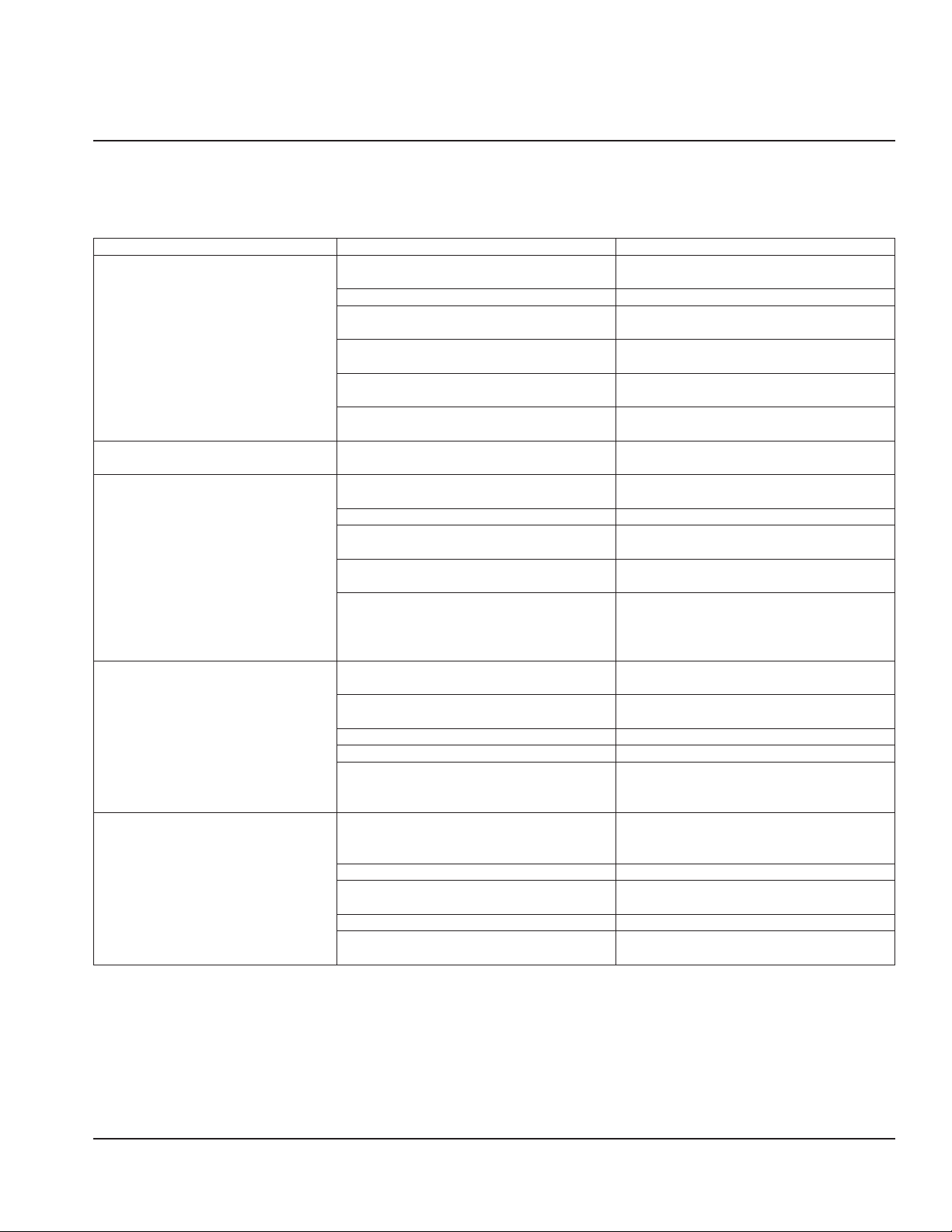
Section 5
Troubleshooting
Before Calling for Service Checklist
If a problem arises during operation of your ice machine, follow the checklist below before calling service. Routine adjustments
and maintenance procedures are not covered by the warranty.
Problem Possible Cause To Correct
Ice machine does not operate. No electrical power to the ice machine and/or
condensing unit.
High pressure cutout tripping. Clean condenser coil. (See page 44)
Energy Saver or other field entered
programming is stopping ice machine.
Water curtain off or stuck open. Water curtain must be installed and swinging
Ice machine is not turned on. Press power button, display must indicate
IB Models Only - Dispenser level thermostat is
open.
Ice machine stops, and can be restarted
by pressing the power switch.
Ice machine does not release ice or is
slow to harvest.
Ice machine does not cycle into harvest
mode.
Ice quality is poor (soft or not clear). Poor incoming water quality. Contact a qualified service company to test
Safety limit feature stopping the ice machine. Refer to “Safety Limit Feature” on the next
Ice machine is dirty. Clean and sanitize the ice machine. (See page
Ice machine is not level. Level the ice machine.
Low air temperature around ice machine head
section.
Fan cycle control does not de-energize
condenser fan motor.
Water regulating valve incorrectly adjusted or
will not close.
The six-minute freeze time lock-in has not
expired yet.
Ice thickness probe is dirty. Clean and sanitize the ice machine. (See page
Ice thickness probe is disconnected. Connect the probe to the control board.
Ice thickness probe is out of adjustment. Adjust the ice thickness probe. (See page 26)
Uneven ice fill (thin at the top of evaporator). Verify sufficient water level in sump trough.
Water filtration is poor. Replace the filter.
Ice machine is dirty. Clean and sanitize the ice machine. (See page
Water dump valve is not working. Disassemble and clean the water dump valve.
Water softener is working improperly (if
applicable).
Replace the fuse/reset the breaker/turn on the
main switch.
Reset to factory defaults. (See page 35)
freely.
“Making Ice”.
Adjust thermostat to maintain correct dispenser
level.
page.
40)
Air temperature must be at least 2°C.
Call for service.
Check for water at condenser drain outlet
in harvest cycle. Contact a qualified service
company to adjust/replace valve if water is
present.
Wait for the freeze lock-in to expire.
40)
Contact a qualified service company to check
refrigeration system.
the quality of the incoming water and make
appropriate filter recommendations.
40)
Repair the water softener.
Part Number: 000013325 Rev 02 6/17 45
Page 46

Troubleshooting Section 5
Problem Possible Cause To Correct
Ice machine produces shallow or
incomplete cubes, or the ice fill pattern
on the evaporator is incomplete.
Low ice capacity. Water inlet valve filter screen is dirty. Remove the water inlet valve and clean the
Ice thickness probe is out of adjustment. Adjust the ice thickness probe. (See page 26)
Water trough level is too low. Check the water level probe position.
Water inlet valve filter screen is dirty. Remove the water inlet valve and clean the
filter screen.
Water filtration is poor. Replace the filter.
Hot incoming water. Connect the ice machine to a cold water supply.
(See page 16)
Water inlet valve is not working. Replace the water inlet valve.
Incorrect incoming water pressure. Water pressure must be 140 kPa - 550 kPa.
Ice machine is not level. Level the ice machine.
filter screen.
Incoming water supply is shut off. Open the water service valve.
Water inlet valve stuck open or leaking. Press the power button and turn off the ice
machine, if water continues to enter water
trough, replace the water inlet valve.
The condenser is dirty. Clean the condenser.
High air temperature entering condenser. Refer to air temperature chart for your model
on page 9.
The harvest assist air compressor is not
functioning.
Call for service.
Safety Limit Feature
In addition to the standard safety controls, such as the high
pressure cutout, your Manitowoc ice machine features builtin safety limits which will stop the ice machine if conditions
arise which could cause a major component failure.
Before calling for service, re-start the ice machine using the
following procedure:
1. Press the power button. The display reads “Off”. Press
the power button again, and the display reads “Making
Ice”.
A. If the safety limit feature has stopped the ice
machine, it will restart after a short delay. Proceed
to step 2.
B. If the ice machine does not restart, see “Ice machine
does not operate” on the previous page.
2. Allow the ice machine to run to determine if the
condition repeats.
A. If the ice machine stops again, the condition has
repeated. Call for service.
B. If the ice machine continues to run, the condition
has corrected itself. Allow the ice machine to
continue running.
46 Part Number: 000013325 Rev 02 6/17
Page 47

Page 48

MANITOWOC ICE
Bringing innovation to the table
2110 SOUTH 26TH STREET, MANITOWOC, WI 54220
WWW.MANITOWOCICE.COM
800-545-5720
WWW.WELBILT.COM
Welbilt provides the world’s top chefs, and premier chain operators or growing independents with industry leading equipment and soluons.
Our cung-edge designs and lean manufacturing taccs are powered by deep knowledge, operator insights, and culinary experse.
All of our products are backed by KitchenCare® – our aermarket, repair, and parts service.
CLEVELAND
CONVOTHERM®
©2017 Welbilt Inc. except where explicitly stated otherwise. All rights reserved. Connuing product improvement may necessitate change of specicaons without noce.
Part Number: 000013325 Rev 02 6/17
DELFIELD®
FITKITCHEN™
FRYMASTER®
GARLAND
KOLPAK®
LINCOLN
MANITOWOC®
MERCO®
MERRYCHEF®
MULTIPLEX®
 Loading...