

Page 1
Indigo™ Series
Air/Water/Remote Condenser Ice
Machines
Technician’s Handbook
Part Number 000014794 5/17
Page 2

Page 3

Safety Notices
Read these precautions to prevent personal injury:
• Read this manual thoroughly before operating,
installing or performing maintenance on the
equipment. Failure to follow instructions in this
manual can cause property damage, injury or death.
• Routine adjustments and maintenance procedures
outlined in this manual are not covered by the
warranty.
• Proper installation, care and maintenance are
essential for maximum performance and trouble-free
operation of your equipment.
• Visit our website www.manitowocice.com for manual
updates, translations, or contact information for
service agents in your area.
• This equipment contains high voltage electricity and
refrigerant charge. Installation and repairs are to be
performed by properly trained technicians aware of
the dangers of dealing with high voltage electricity
and refrigerant under pressure. The technician must
also be certified in proper refrigerant handling
and servicing procedures. All lockout and tag out
procedures must be followed when working on this
equipment.
• This equipment is intended for indoor use only. Do
not install or operate this equipment in outdoor
areas.
• As you work on this equipment, be sure to pay close
attention to the safety notices in this handbook.
Disregarding the notices may lead to serious injury
and/or damage to the equipment.
Page 4

Warning
n
Follow these electrical requirements during
installation of this equipment.
• All field wiring must conform to all applicable
codes of the authority having jurisdiction. It is
the responsibility of the end user to provide the
disconnect means to satisfy local codes. Refer to
rating plate for proper voltage.
• This appliance must be grounded.
• This equipment must be positioned so that
the plug is accessible unless other means for
disconnection from the power supply (e.g., circuit
breaker or disconnect switch) is provided.
• Check all wiring connections, including factory
terminals, before operation. Connections can
become loose during shipment and installation.
Page 5

Warning
n
Follow these precautions to prevent personal
injury during installation of this equipment:
• Installation must comply with all applicable
equipment fire and health codes with the authority
having jurisdiction.
• To avoid instability the installation area must be
capable of supporting the combined weight of
the equipment and product. Additionally the
equipment must be level side to side and front to
back.
• Remove all removable panels before lifting and
installing and use appropriate safety equipment
during installation and servicing. Two or more
people are required to lift or move this appliance to
prevent tipping and/or injury.
• Do not damage the refrigeration circuit when
installing, maintaining or servicing the unit.
• Connect to a potable water supply only.
• This equipment contains refrigerant charge.
Page 6

Warning
n
Follow these precautions to prevent personal
injury while operating or maintaining this
equipment.
• Refer to nameplate to identify the type of
refrigerant in your equipment.
• Only trained and qualified personnel aware of the
dangers are allowed to work on the equipment.
• Read this manual thoroughly before operating,
installing or performing maintenance on the
equipment. Failure to follow instructions in this
manual can cause property damage, injury or
death.
• Crush/Pinch Hazard. Keep hands clear of moving
components. Components can move without
warning unless power is disconnected and all
potential energy is removed.
• Moisture collecting on the floor will create a
slippery surface. Clean up any water on the floor
immediately to prevent a slip hazard.
Page 7

Warning
n
Follow these precautions to prevent personal
injury while operating or maintaining this
equipment.
• Objects placed or dropped in the bin can affect
human health and safety. Locate and remove any
objects immediately.
• Never use sharp objects or tools to remove ice or
frost.
• Do not use mechanical devices or other means to
accelerate the defrosting process.
• When using cleaning fluids or chemicals, rubber
gloves and eye protection (and/or face shield) must
be worn.
DANGER
Do not operate equipment that has been misused,
abused, neglected, damaged, or altered/modified
from that of original manufactured specifications.
This appliance is not intended for use by persons
(including children) with reduced physical, sensory
or mental capabilities, or lack of experience and
knowledge, unless they have been given supervision
concerning use of the appliance by a person
responsible for their safety. Do not allow children to
play with, clean or maintain this appliance without
proper supervision.
Page 8

Warning
n
Follow these precautions to prevent personal injury
during use and maintenance of this equipment:
• It is the responsibility of the equipment owner to
perform a Personal Protective Equipment Hazard
Assessment to ensure adequate protection during
maintenance procedures.
• Do Not Store Or Use Gasoline Or Other Flammable
Vapors Or Liquids In The Vicinity Of This Or Any
Other Appliance. Never use flammable oil soaked
cloths or combustible cleaning solutions for
cleaning.
• All covers and access panels must be in place and
properly secured when operating this equipment.
• Risk of fire/shock. All minimum clearances must be
maintained. Do not obstruct vents or openings.
• Failure to disconnect power at the main power
supply disconnect could result in serious injury or
death. The power switch DOES NOT disconnect all
incoming power.
• All utility connections and fixtures must be
maintained in accordance with the authority
having jurisdiction.
• Turn off and lockout all utilities (gas, electric,
water) according to approved practices during
maintenance or servicing.
Page 9

Table of Contents
General Information
How to Read a Model Number ................ 15
Head Sections.............................15
Ice Cube Sizes ................................. 16
Model/Serial Number Location ............... 16
Model Numbers...............................17
Air-Water-Remote Condenser Models ..... 17
Ice Machine Warranty Information............ 18
LuminIce® II ...................................19
Installation
Ice Deflector .............................. 21
Location of Ice Machine.......................22
Clearance Requirements......................23
Air, Water, Remote Condenser Models......23
Ice Machine Heat of Rejection ................ 24
Installation on a Bin........................... 25
Ice Machine on a Dispenser Installation ...... 25
Lineset Applications .......................... 26
Remote Condenser ........................ 27
Remote Ice Machine Usage with
Non-Manitowoc Multi-Circuit Condensers.... 32
Maintenance
Cleaning and Sanitizing ...................... 37
General ................................... 37
Cleaning/Sanitizing Procedure............. 39
Preventative Maintenance Cleaning
Procedure................................. 39
Exterior Cleaning ..........................39
Cleaning / Sanitizing Procedure ..............40
Cleaning Procedure .......................40
Sanitizing Procedure ......................43
Parts Removal for Cleaning/Sanitizing...... 46
Preventative Maintenance Cleaning
Procedure..................................... 51
Removal from Service/Winterization .........53
Air-Cooled Ice Machines ...................53
Water-Cooled Ice Machines................54
Part Number 000014794 5/17 9
Page 10

Operation
Control Panel Features........................ 55
Buttons ................................... 55
Display Panel.............................. 56
Menu Navigation Overview...................57
Display Panel Navigation .....................58
Alerts and Messages .......................... 60
Main Menu....................................61
Machine Info Menu ........................... 62
Password Entry ...............................63
Reset Password To Factory Defaults ........ 65
Set-Up Menu ..................................66
Language .................................67
Time & Date...............................67
Time Configuration........................ 69
Units......................................69
Ice Clarity ................................. 70
LCD Brightness............................ 70
Password On . . . . . . . . . . . . . . . . . . . . . . . . . . . . . . 71
Edit Password .............................71
Clean Minder.............................. 71
IAuCS Runtime ............................ 72
Air Filter................................... 72
Water Filter................................ 73
LuminIce® Reminder....................... 74
Ice Bin Level Sensor .......................75
USB Setup................................. 75
Factory Defaults...........................75
Energy Saver Menu ...........................76
Ice Program ...............................77
Water Miser ...............................78
Statistics .................................. 78
Service Menu ................................. 79
Data History............................... 81
Real Time Data ............................ 82
Diagnostics ............................... 84
Manual Harvest ........................... 85
Replace Control Board.....................85
USB Setup................................. 85
Event Log Menu...........................86
Event Log .................................87
10 Part Number 000014794 5/17
Page 11

USB Flash Drive Specifications and
Formatting................................ 92
Upgrading Firmware with a Flash Drive .... 94
Exporting Data to a Flash Drive ............ 96
Operational Checks ...........................98
General ................................... 98
Ice Thickness Check ....................... 99
Sequence of Operation ......................101
Self Contained Air or Water Cooled........101
Energized Parts Chart Self Contained
Models...................................105
Remote Condenser .......................107
Energized Parts Chart Remote Models.....111
Troubleshooting
Safety Limits .................................113
Safe Operation Mode.....................114
Water Assist Harvest......................114
Water Thaw Cycle ........................115
Analyzing Why a Safety Limit Stopped
the Ice Machine ..........................116
Safety Limit #1 ...........................116
Safety Limit #2 ...........................118
Troubleshooting By Symptom ...............119
Reset To Factory Defaults .................120
Symptom #1 Ice Machine Will Not Run ....121
Symptom #2 - Freeze Cycle Refrigeration
System Operational Analysis Tables .......126
Symptom #3 & #4 Harvest Problems
Self-contained Air, Water & Remote
Condenser Models .......................155
Symptom #3 Self-Contained Air or
Water-cooled.............................156
Symptom #3 - Remote Condenser ........158
Symptom #4 Self-Contained Air,
Water-Cooled Or Remote .................160
Component Check Procedures
Electrical Components .......................163
Control Board, Display Board and Touch
Pad ......................................163
Control Board Relay Test ..................166
Part Number 000014794 5/17 11
Page 12

Programming A Replacement Control
Board . . . . . . . . . . . . . . . . . . . . . . . . . . . . . . . . . . . . 167
Main Fuse ................................169
Bin Switch................................170
Water Level Control Circuitry..............173
Ice Thickness Probe (Initiates Harvest).....179
High Pressure Cutout (HPCO) Control .....184
Fan Cycle Control.........................187
Thermistors ..............................188
Harvest Assist Air Pump ..................191
Compressor Electrical Diagnostics ........192
Diagnosing Start Components ............194
Refrigeration Components ..................197
Head Pressure Control Valve ..............197
Harvest Pressure Regulating (HPR)
System Remote Condenser Only ..........201
Water Regulating Valve ...................204
Refrigerant Recovery/Evacuation............205
Self-Contained Model Procedure..........205
Remote Condenser Model Procedure .....209
System Contamination Clean-Up ............215
Determining Severity Of Contamination ..215
Cleanup Procedure .......................217
Replacing Pressure Controls Without
Removing Refrigerant Charge.............220
Liquid Line Filter-Driers...................221
Total System Refrigerant Charge ..........222
Charts
Cycle Times/24-Hour Ice Production/ Refrigerant
Pressure Charts ..............................225
I0300 Series ..............................226
I0320 Series ..............................228
I0450 Series ..............................230
I0500 Series ..............................232
I0520 Series ..............................235
I0600 Series ..............................237
I0850 Series ..............................243
I0906 Series ..............................246
I1000 Series ..............................249
I1106 Series ..............................252
12 Part Number 000014794 5/17
Page 13

I1200 Series ..............................255
I1400 Series ..............................257
I1406 Series ..............................260
I1800 Series ..............................263
Diagrams
Wiring Diagrams .............................267
Wiring Diagram Legend ..................267
I0300/I0450/I0500/I0520 - 1ph air/water ..268
I0320 - 1ph air/water .....................269
I0500 - 1ph Remote.......................270
I0600/I0606/I0850/I0906/I1000/I1106/I1200 -
1ph air/water.............................271
I0600/I606/I0850/I906/I1000/I1106/I1200 -
3ph air/water.............................272
I0600/I0606/I0850/I0906/I1000/I1106 - 1ph
Remote ..................................273
I0600/I0606/I0850/I0906/I1000/I1106 - 3ph
Remote ..................................274
I1400/I1406/I1800 - 1ph air/water.........275
I1400/I1406/I1800 - 3ph air/water.........276
I1400/II1406/I1800 1ph Remote...........277
I1400/I1406/I1800 - 3ph Remote ..........278
I1400 ECM Fan Motor - 1PH air ............279
I1400 ECM Fan Motor - 3PH air ............280
Electrical Noise Filter .....................281
Electronic Control Board.....................282
Refrigeration Tubing Schematics ............283
Self-Contained Air or Water-Cooled .......283
Remote Condenser Models ...............285
Part Number 000014794 5/17 13
Page 14

THIS PAGE INTENTIONALLY LEFT BLANK
14 Part Number 000014794 5/17
Page 15
IC
I
IB
Y
463 -460/60/3
r
Full Model Number
General Information
How to Read a Model Number
HEAD SECTIONS
P -Correctional Model
M -Marine Model
6 -60HZ
# HERTZ
5 -50HZ
J - Japan
X -LuminIce
K -Korea
Regulating Valve
HP -High Pressure Wate
251 -230/50/1
263 -208-230 /60/3
161 -115/60/1
261 -208-230 /60/1
VOLTAGE
A -Self-Contained Air-Cooled
CONDENSER TYPE
W -Self-Contained Water-Cooled
N -Remote Air-Cooled
C -CVD Air-Cooled
DC -IB Dice Model
YC -IB Half Dice
I Y 1000 W3 –263PHPX
Base Model Number
-Half-Dice
D -Dice
R -Regular
ICE CUBE SIZE
Not Used On IB Models
Part Number 000014794 5/17 15
-Ice Beverage
E MACHINE MODEL
-Indigo Model
3 -Three Phase
E -WRAS 50 Cycle Only
No Indicator -1 Phase
Ice Machine Series
Page 16
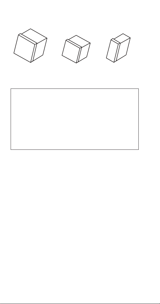
Ice Cube Sizes
Regular
1-1/8" x 1-1/8" x 7/8"
2.86 x 2.86 x 2.22 cm
All Manitowoc ice machines require the ice storage
system (bin, dispenser, etc.) to incorporate an ice
deflector.
Prior to using a non-Manitowoc ice storage system
with other Manitowoc ice machines, contact
the manufacturer to assure their ice deflector is
compatible with Manitowoc ice machines.
Dice
7/8" x 7/8" x 7/8"
2.22 x 2.22 x2.22 cm
Warning
n
Half Dice
3/8" x 1-1/8" x 7/8"
0.95 x 2.86 x 2.22 cm
Model/Serial Number Location
These numbers are required when requesting
information from your local Manitowoc Distributor,
service representative, or Manitowoc Ice. The model
and serial number are listed on the OWNER WARRANTY
REGISTRATION CARD. They are also listed on the MODEL/
SERIAL NUMBER DECAL affixed to the front and rear of
the ice machine.
16 Part Number 000014794 5/17
Page 17
Model Numbers
AIRWATERREMOTE CONDENSER MODELS
Self-Contained
Air-Cooled
ID0302A
IY0304A
ID0322A
IY0324A
ID0452A
IY0454A
IR0500A
ID0502A
IY0504A
IR0520A
ID0522A
IY0524A
ID0602A
IY0604A
ID0606A
IY0606A
IR0850A
ID0852A
IY0854A
IR0906A
ID0906A
IY0906A
ID1002A
IY1004A
ID1106A
IY1106A
ID1202A
IY1204A
ID1402A
IY1404A
ID1406A
IY1406A
IR1800A
ID1802A
IY1804A
NOTE: Marine and Prison models have a M or P suffix - Example
ID0853WM
Suffix at the end of the model number:
3 = 3 phase unit - Example IY1004A3
Self-Contained
Water-Cooled
ID0303W
IY0305W
ID0323W
IY0325W
D0453W
IY0455W
IR0501W
ID0503W
IY0505W
IR0521W
ID0523W
IY0525W
ID0603W
IY0605W
ID0606W
IY0606W
IR0851W
ID0853W
IY0855W
IR0906W
ID0906W
IY0906W
ID1003W
IY1005W
ID1106W
IY1106W
ID1203W
IY1205W
ID1403W
IY1405W
ID1406W
IY1406W
IR1801W
ID1803W
IY1805W
Remote
----
----
----
----
----
---IR0590N
ID0592N
IY0594N
----
----
---ID0692N
IY0694N
ID0696N
IY0696N
IR0890N
ID0892N
IY0894N
IR0996N
ID0996N
IY0996N
ID1092N
IY1094N
ID1196N
IY1196N
----
---ID1492N
IY1494N
ID1496N
IY1496N
IR1890N
ID1892N
IY1894N
Part Number 000014794 5/17 17
Page 18

K = Korean model.
J = Japan model
HP = High Pressure Water Regulating Valve - I0450/I0500 Water
Cooled Condenser models
Ice Machine Warranty Information
For warranty information visit:
http://www.manitowocice.com/Service/Warranty
• Warranty Verification
• Warranty Registration
• View and download a copy of the warranty Owner
Warranty Registration Card
Warranty coverage begins the day the ice machine is
installed.
18 Part Number 000014794 5/17
Page 19

LuminIce® II
The LuminIce® growth inhibitor recirculates the air in the
ice machine foodzone over a UV bulb. This process will
inhibit the growth of common micro-organisms on all
exposed foodzone surfaces.
• LuminIce® bulbs require replacement on a yearly
basis.
• The control board can be set to automatically display
a reminder after 12 months.
• A remote light is available for reminder indication.
NOTE: LuminIce® and LuminIce® II bulbs are not
interchangeable; verify your model before ordering a
replacement bulb.
Cleanup Procedure for Accidental Bulb Breakage
The cleanup procedure is identical to the procedure used
to clean up compact fluorescent (CFL) or fluorescent tube
lights. These lights contain a small amount of mercury
sealed within a glass tube. Breaking these types of lights
will release mercury and mercury vapor. The broken bulb
can continue to release mercury vapor until it is cleaned
up and removed.
The latest EPA procedures can be viewed on their website
at www.epa.gov/cfl/cflcleanup.html.
Part Number 000014794 5/17 19
Page 20

THIS PAGE INTENTIONALLY LEFT BLANK
20 Part Number 000014794 5/17
Page 21

Installation
Warning
n
PERSONAL INJURY POTENTIAL
Remove all ice machine panels before lifting.
Caution
,
The ice machine head section must be protected if it
will be subjected to temperatures below 32°F (0°C).
Failure caused by exposure to freezing temperatures
is not covered by the warranty. See “Removal from
Service/Winterization” on page 53.
ICE DEFLECTOR
An ice deflector is required for all ice machines installed
on a bin.
Part Number 000014794 5/17 21
Page 22

Location of Ice Machine
The location selected for the ice machine must meet
the following criteria. If any of these criteria are not met,
select another location.
• The location must be free of airborne and other
contaminants.
• Self contained air and water cooled - The air
temperature must be at least 35°F (1.6°C), but must
not exceed 110°F (43.4°C).
• Remote air cooled - The air temperature must be at
least -20°F (-29°C), but must not exceed 120°F (49°C)
• Ice Making Water Inlet - Water Pressure must be at
least 20 psi (1.38 bar), but must not exceed 80 psi
(5.52 bar).
• Condenser Water Inlet - Water Pressure must be at
least 20 psi (1.38 bar), but must not exceed 150 psi
(10.34 bar).
• The location must not be near heat-generating
equipment or in direct sunlight and protected from
weather.
• The location must not obstruct air flow through or
around the ice machine. Refer to chart below for
clearance requirements.
• The ice machine must be protected if it will be
subjected to temperatures below 32°F (0°C). Failure
caused by exposure to freezing temperatures is not
covered by the warranty. See “Removal from Service/
Winterization”
22 Part Number 000014794 5/17
Page 23
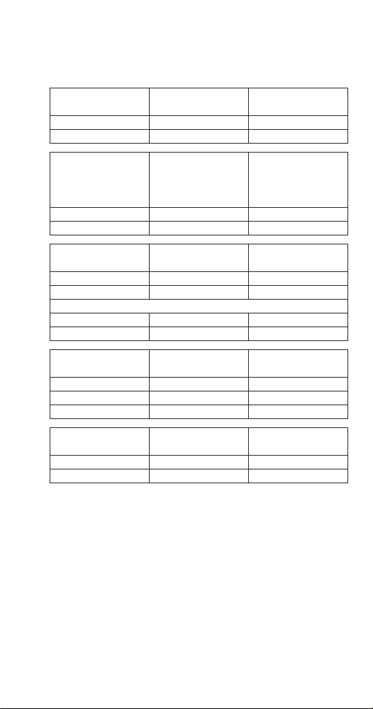
Clearance Requirements
AIR, WATER, REMOTE CONDENSER MODELS
I0300
Top/Sides 16" (40.6 cm) 8" (20.3 cm)
Back 5" (12.7 cm) 5" (12.7 cm)
I0450 - I0500
I0600 -I0606
I0850 - I0906
I1000 - I1106
Top/Sides 8" (20.3 cm) 8" (20.3 cm)
Back 5" (12.7 cm) 5" (12.7 cm)
I0320 - I0520
Top/Sides 12" (30.5 cm) 8" (20.3 cm)
Back 5" (12.7 cm) 5" (12.7 cm)
I0500 Tropical Rating 230/50/1 Air-Cooled Only
Top 24” (61 cm) N/A
Sides/back 12” (30.5 cm) N/A
I1200
Top 8" (20.3 cm) 8" (20.3 cm)
Sides 12" (30.5 cm) 8" (20.3 cm)
Back 5" (12.7 cm) 5" (12.7 cm)
I1400 - I1406
I1800
Top/Sides 24" (61.0 cm) 8" (20.3 cm)
Back 12" (30.5 cm) 5" (12.7 cm)
Self-Contained
Air-Cooled
Self-Contained
Air-Cooled
Self-Contained
Air-Cooled
Self-Contained
Air-Cooled
Self-Contained
Air-Cooled
Self-Contained
Water-Cooled
Water-Cooled and
Remote
Water-Cooled and
Remote
Water-Cooled
and Remote
Water-Cooled
and Remote
Part Number 000014794 5/17 23
Page 24

Ice Machine Heat of Rejection
Series Ice
Machine
I0300 4600 5450
I0320 3300 4500
I0450 5400 6300
I0500 6100 6900
I0520 5400 6300
I0600/I0606 9000 13900
I0850 13000 16000
I0906 12700 14800
I1000/I1106 16250 18600
I1200 20700 24500
I1400/I1406 23500 27000
I1800 30000 35000
*BTU/Hour
Because the heat of rejection varies during the ice making cycle,
the figure shown is an average.
Air Conditioning* Peak
Heat of Rejection
24 Part Number 000014794 5/17
Page 25

Installation on a Bin
An ice deflector is required for all bin installations and is
included with all Manitowoc bins. Order the appropriate
deflector kit (30" or 48") for any bin without a deflector.
Warning
n
PERSONAL INJURY POTENTIAL
Do not operate any ice machine with the deflector
removed.
Ice Machine on a Dispenser Installation
No deflector is needed for machines that match the size
of the dispenser (30" head section on a 30" dispenser)
unless required by the dispenser manufacturer. Adapters
are required when a smaller ice machine is going on a
larger dispenser (22" machine on a 30" dispenser).
Part Number 000014794 5/17 25
Page 26

Lineset Applications
Warning
n
The 60-month compressor warranty (including the
36-month labor replacement warranty) will not
apply if the Manitowoc Ice Machine, Condenser or
QuietQube® Condensing Unit were not installed
according to specifications. This warranty also will
not apply if the refrigeration system is modified with
a condenser, heat reclaim device, or other parts or
assemblies not manufactured by Manitowoc Ice.
Caution
,
Recovery locations vary by model. Verify you are
making the correct connections for your model
to prevent accidental release of high pressure
refrigerant.
Important
Manitowoc remote systems are only approved and
warranted as a complete new package. Warranty on
the refrigeration system will be void if new equipment
is connected to pre-existing (used) tubing, remote
condenser, remote condensing unit or ice machine
head section.
26 Part Number 000014794 5/17
Page 27
REMOTE CONDENSER
Ice Machine
I0590N JC0495
I0690N
I0696N
I0890N
I0996N
I1090N
I1196N
I1490N
I1496N
I1890N
*Line Set Discharge Line Liquid Line
RT 1/2" (1.27 cm) 5/16" (.79 cm)
RL 1/2" (1.27 cm) 3/8" (.95 cm)
Air Temperature Around the Condenser
Minimum Maximum
-20°F (-29°C) 120°F (49°C)
Remote Single
Circuit Condenser
JC0895
JC0995
JC1395
Line Set*
RT-20-R404A
RT-35-R404A
RT-50-R404A
RT-20-R404A
RT-35-R404A
RT-50-R404A
RT-20-R404A
RT-35-R404A
RT-50-R404A
RL-20-R404A
RL-35-R404A
RL-50-R404A
Part Number 000014794 5/17 27
Page 28

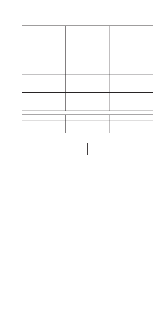
Additional Refrigerant Charge For 51' to 100' Line Sets
Ice Machine Condenser Additional Amount of
Refrigerant To Be Added
To Nameplate Charge
I0590N JC0495 1.5 lbs - 680g
I0690N JC0895 1.5 lbs - 680g
I0696N JC0895 2 lbs - 907g
I0890N JC0895 2 lbs - 907g
I0996N JC0995 2 lbs - 907g
I1090N JC0995 2 lbs - 907g
I1196N JC0995 2 lbs - 907g
I1490N JC1395 2 lbs - 907g
I1496N JC1395 2 lbs - 907g
I1890N JC1395 2 lbs - 907g
28 Part Number 000014794 5/17
Page 29
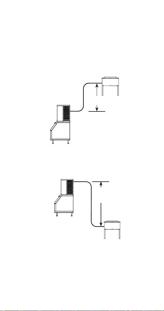
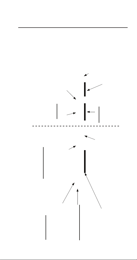
Calculating Allowable Lineset Distance
Line Set Length
The maximum length is 100' (30.5 m).
Line Set Rise/Drop
The maximum rise is 35' (10.7 m).
The maximum drop is 15' (4.5 m).
35 FT. (10.7 M)
MAXIMUM DISTANCE
35 ft. (10.7 m) Rise: The maximum distance the
Condenser or Condensing Unit can be above the ice
machine.
15 FT. (4.5 M)
MAXIMUM
DISTANCE
15 ft. (4.5 m) Drop: The maximum distance the
Condenser or Condensing Unit can be below the ice
machine.
Part Number 000014794 5/17 29
Page 30

Calculated Line Set Distance
The maximum calculated distance is 150' (45.7 m).
Line set rises, drops, horizontal runs (or combinations
of these) in excess of the stated maximums will exceed
compressor start-up and design limits. This will cause
poor oil return to the compressor.
Make the following calculations to make sure the line set
layout is within specifications.
1. Insert the measured rise into the formula below.
Multiply by 1.7 to get the calculated rise.
(Example: A condenser located 10 feet above the ice
machine has a calculated rise of 17 feet.)
2. Insert the measured drop into the formula below.
Multiply by 6.6 to get the calculated drop.
(Example. A condenser located 10 feet below the ice
machine has a calculated drop of 66 feet.)
3. Insert the measured horizontal distance into the
formula below. No calculation is necessary.
4. Add together the calculated rise, calculated drop,
and horizontal distance to get the total calculated
distance. If this total exceeds 150' (45.7 m), move
the condenser to a new location and perform the
calculations again.
30 Part Number 000014794 5/17
Page 31

Maximum Line Set Distance Formula
Step 1
Measured Rise ____ X 1.7 = ______Calculated Rise
(35 ft. Max)
Step 2
Measured Drop ____ X 6.6 = ______Calculated Drop
(15 ft. Max.)
Step 3
Measured Horizontal Distance = _________ Horizontal
(100 ft. Max.) Distance
Step 4
Total Calculated Distance = ___________ Total Calculated
(150 ft. Max.) Distance
Part Number 000014794 5/17 31
Page 32

Remote Ice Machine Usage with NonManitowoc Multi-Circuit Condensers
Warranty
The sixty (60) month compressor warranty, including
thirty six (36) month labor replacement warranty, shall
not apply when the remote ice machine is not installed
within the remote specifications. The foregoing warranty
shall not apply to any ice machine installed and/or
maintained inconsistent with the technical instructions
provided by Manitowoc Ice. Performance may vary from
Sales specifications. ARI certified standard ratings only
apply when used with a Manitowoc remote condenser.
If the design of the condenser meets the specifications,
Manitowoc’s only approval is for full warranty coverage
to be extended to the Manitowoc manufactured part of
the system. Since Manitowoc does not test the condenser
in conjunction with the ice machine, Manitowoc will not
endorse, recommend, or approve the condenser, and will
not be responsible for its performance or reliability.
Important
Manitowoc warrants only complete new and unused
remote packages. Guaranteeing the integrity of a
new ice machine under the terms of our warranty
prohibits the use of pre-existing (used) tubing or
condensers.
32 Part Number 000014794 5/17
Page 33

Head Pressure Control Valve
Any remote condenser connected to a Manitowoc
Ice Machine must have a head pressure control valve
(available from Manitowoc Distributors) installed on the
condenser package. Manitowoc will not accept substitute
“off the shelf” head pressure control valves
CAUTION
,
Do not use a fan cycling control to try to maintain
discharge pressure. Compressor failure will result.
Fan Motor
The condenser fan must be on during the complete ice
machine freeze cycle (do not cycle on fan cycle control).
The ice maker has a condenser fan motor circuit for use
with a Manitowoc condenser. It is recommended that
this circuit be used to control the condenser fan(s) on the
multi-circuit condenser to assure it is on at the proper
time. Do not exceed the rated amps for the fan motor
circuit listed on the ice machine’s serial tag.
Internal Condenser Volume
The multi-circuit condenser internal volume must not be
less than or exceed that used by Manitowoc (see chart on
page 35). Do not exceed internal volume and try to add
charge to compensate, as compressor failure will result.
Part Number 000014794 5/17 33
Page 34

Condenser ∆T
∆T is the difference in temperature between the
condensing refrigerant and entering air. The ∆T should be
15 to 20°F (-9.4 to -6.6°C) at the beginning of the freeze
cycle (peak load conditions) and drop down to 12 to 17°F
(-11.1 to -8.3°C) during the last 75% of the freeze cycle
(average load conditions).
Refrigerant Charge
Remote ice machines have the serial plate refrigerant
charge (total system charge) located in the ice maker
section. (Remote condensers and line sets are supplied
with only a vapor charge.)
CAUTION
,
Never add more than nameplate charge to ice
machine for any application.
Quick Connect Fittings
The ice machine and line sets come with quick connect
fittings. It is recommended that matching quick connects
(available through Manitowoc Distributors) be installed
in the multi-circuit condenser, and that a vapor “holding”
charge, 5 oz. (150 ml), of proper refrigerant be added to
the condenser prior to connection of the ice machine or
line set to the condenser.
34 Part Number 000014794 5/17
Page 35

Head
Control
Pressure
8368093I0690
P/N
ValveType Charge Average
no
substitutes
Male Ends
Quick Connect Stubs
Design
& Burst
Volume (cu ft)
Discharge Liquid
Pressure
Min Max 500 psig
Peak Btu/
P/N
coupling
P/N
coupling
500 psig
2500 psig
hr
Btu/hr
8360343
8360353
Burst
(34.7 bar)
(3447 kpa)
kpa)
(17237
2500 psig
mounting
bar)
(172.37
8360053
flange P/N
8360063
flange P/N
Refrigerant Heat of Rejection Internal Condenser
R404A 6.5 lbs. 9000 13900 0.045 0.060
R404A 7 lbs. 13000 16000 0.045 0.060
R404A 8.5 lbs. 16250 18600 0.045 0.060
R404A 11 lbs. 23500 27000 0.085 0.105 mounting
Ice
Model
Machine
Part Number 000014794 5/17 35
I0590 R404A 6 lbs. 6100 6900 0.020 0.035 Design
I0696
I0890 R404A 8.5 lbs. 13000 16000 0.045 0.060
I0990
I0996
I1090
I1190
I1196
I1490
I1890 R404A 12.5 lbs. 30000 35000 0.085 0.105
I1496
Page 36

THIS PAGE INTENTIONALLY LEFT BLANK
36 Part Number 000014794 5/17
Page 37

Maintenance
Cleaning and Sanitizing
GENERAL
You are responsible for maintaining the ice machine
in accordance with the instructions in this manual.
Maintenance procedures are not covered by the warranty.
Clean and sanitize the ice machine every six months
for efficient operation. If the ice machine requires
more frequent cleaning and sanitizing, consult a
qualified service company to test the water quality and
recommend appropriate water treatment. An extremely
dirty ice machine must be taken apart for cleaning and
sanitizing.
Manitowoc Ice Machine Cleaner and Sanitizer are the only
products approved for use in Manitowoc ice machines.
Part Number 000014794 5/17 37
Page 38

Caution
,
Use only Manitowoc approved Ice Machine Cleaner
and Sanitizer for this application (Manitowoc Cleaner
part number 9405463 and Manitowoc Sanitizer part
number 9405653). It is a violation of Federal law to
use these solutions in a manner inconsistent with
their labeling. Read and understand all labels printed
on bottles before use.
Caution
,
Do not mix Cleaner and Sanitizer solutions together.
It is a violation of Federal law to use these solutions in
a manner inconsistent with their labeling.
Warning
n
Wear rubber gloves and safety goggles (and/or
face shield) when handling Ice Machine Cleaner or
Sanitizer.
38 Part Number 000014794 5/17
Page 39

CLEANING/SANITIZING PROCEDURE
This procedure must be performed a minimum of once
every six months.
• The ice machine and bin must be disassembled
cleaned and sanitized.
• All ice produced during the cleaning and sanitizing
procedures must be discarded.
• Removes mineral deposits from areas or surfaces that
are in direct contact with water.
PREVENTATIVE MAINTENANCE CLEANING PROCEDURE
• This procedure cleans all components in the water
flow path, and is used to clean the ice machine
between the bi-yearly cleaning/sanitizing procedure.
• This technology will also allow initiation and
completion of a clean or sanitize cycle, after which
the ice machine automatically starts ice making
again.
EXTERIOR CLEANING
Clean the area around the ice machine as often as
necessary to maintain cleanliness and efficient operation.
Wipe surfaces with a damp cloth rinsed in water to
remove dust and dirt from the outside of the ice machine.
If a greasy residue persists, use a damp cloth rinsed in a
mild dish soap and water solution. Wipe dry with a clean,
soft cloth.
The exterior panels have a clear coating that is stain
resistant and easy to clean. Products containing abrasives
will damage the coating and scratch the panels.
• Never use steel wool or abrasive pads for cleaning.
• Never use chlorinated, citrus based or abrasive
cleaners on exterior panels and plastic trim pieces.
Part Number 000014794 5/17 39
Page 40

Cleaning / Sanitizing Procedure
Caution
,
Use only Manitowoc approved Ice Machine Cleaner
and Sanitizer for this application (Manitowoc Cleaner
part number 9405463 and Manitowoc Sanitizer part
number 9405653). It is a violation of Federal law to
use these solutions in a manner inconsistent with
their labeling. Read and understand all labels printed
on bottles before use.
CLEANING PROCEDURE
Caution
,
Do not mix Cleaner and Sanitizer solutions together.
It is a violation of Federal law to use these solutions in
a manner inconsistent with their labeling.
Warning
n
Wear rubber gloves and safety goggles (and/or
face shield) when handling Ice Machine Cleaner or
Sanitizer.
Ice machine cleaner is used to remove lime scale and
mineral deposits. Ice machine sanitizer disinfects and
removes algae and slime.
NOTE: Although not required and dependent on your
installation, removing the ice machine top cover may
allow easier access.
40 Part Number 000014794 5/17
Page 41

Step 1 Open the front door to access the evaporator
compartment. Ice must not be on the evaporator during
the clean/sanitize cycle. Follow one of the methods
below:
• Press the power switch at the end of a harvest cycle
after ice falls from the evaporator(s).
• Press the power switch and allow the ice to melt.
Caution
,
Never use anything to force ice from the evaporator.
Damage may result.
Step 2 Remove all ice from the bin/dispenser.
Step 3 Press the clean switch. Water will flow through
the water dump valve and down the drain. Wait until the
water trough refills and the display indicates add solution
(approximately 1 minute), then add the proper amount of
ice machine cleaner.
Model Amount of Cleaner
I0300/I0320/I0520 3 ounces (90 ml)
I0450/I0500/I0600/I0606/I0850
I0906/I1000/I1106/I1200
I1400/I1406/I1800 9 ounces (265 ml)
5 ounces (150 ml)
Part Number 000014794 5/17 41
Page 42

Step 4 Wait until the clean cycle is complete
(approximately 24 minutes). Then disconnect power to
the ice machine (and dispenser when used).
Warning
n
Disconnect the electric power to the ice machine at
the electric service switch box.
Step 5 Remove parts for cleaning.
Please refer to the proper parts removal for your ice
machine. Continue with step 6 when the parts have been
removed.
Single Evaporator Ice Machines - page 48
Step 6 Mix a solution of cleaner and lukewarm water.
Depending upon the amount of mineral buildup, a larger
quantity of solution may be required. Use the ratio in the
table below to mix enough solution to thoroughly clean
all parts.
Solution Type Water Mixed With
Cleaner 1 gal. (4 L) 16 oz (500 ml)
cleaner
CAUTION
,
Do not clean the ice thickness probe in a dishwasher.
Permanent damage to the ice thickness probe will
occur.
42 Part Number 000014794 5/17
Page 43

Step 7 Use 1/2 of the cleaner/water mixture to clean
all components. The cleaner solution will foam when
it contacts lime scale and mineral deposits; once the
foaming stops use a soft-bristle nylon brush, sponge or
cloth (NOT a wire brush) to carefully clean the parts. Soak
parts for 5 minutes (15 - 20 minutes for heavily scaled
parts). Rinse all components with clean water.
Step 8 While components are soaking, use 1/2 of the
cleaner/water solution to clean all food zone surfaces of
the ice machine and bin (or dispenser). Use a nylon brush
or cloth to thoroughly clean the following ice machine
areas:
• Side walls
• Base (area above water trough)
• Evaporator plastic parts - including top, bottom, and
sides
• Bin or dispenser
Rinse all areas thoroughly with clean water.
SANITIZING PROCEDURE
Step 9 Mix a solution of sanitizer and lukewarm water.
Solution Type Water Mixed With
Sanitizer 3 gal. (12 L) 2 oz (60 ml) sanitizer
Step 10 Use 1/2 of the sanitizer/water solution to
sanitize all removed components. Use a spray bottle to
liberally apply the solution to all surfaces of the removed
parts or soak the removed parts in the sanitizer/water
solution. Do not rinse parts after sanitizing.
Part Number 000014794 5/17 43
Page 44

Step 11 Use 1/2 of the sanitizer/water solution to
sanitize all food zone surfaces of the ice machine and bin
(or dispenser). Use a spray bottle to liberally apply the
solution. When sanitizing, pay particular attention to the
following areas:
• Side walls
• Base (area above water trough)
• Evaporator plastic parts - including top, bottom and
sides
• Bin or dispenser
Do not rinse the sanitized areas.
Step 12 Replace all removed components.
Step 13 Wait 20 minutes.
Step 14 Reapply power to the ice machine and press
the Clean button.
44 Part Number 000014794 5/17
Page 45

Step 15 Wait until the water trough refills and the
display indicates add solution (approximately 1 minute).
Add the proper amount of Manitowoc Ice Machine
Sanitizer to the water trough by pouring between the
water curtain and evaporator.
Model Amount of Sanitizer
I0300/I0320/I0520 3 ounces (90 ml)
I0450/I0500/I0600/I0606/I0850
I0906/I1000/I1106/I1200
I1400/I1406/I1800 6 ounces (180 ml)
3 ounces (90 ml)
Step 16 Select Auto Ice On, press the Checkmark and
close and secure the front door. The ice machine will
automatically start ice making after the sanitize cycle is
complete (approximately 24 minutes).
Part Number 000014794 5/17 45
Page 46
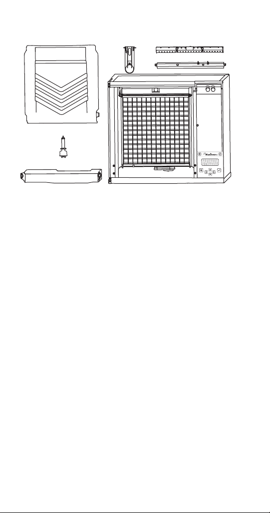
PARTS REMOVAL FOR CLEANING/SANITIZING
Off
On / Off Mode
[ ]
!
D
E
A
C
B
A. Remove the water curtain
• Gently flex the curtain in the center and remove it
from the right side.
• Slide the left pin out.
B. Remove the water trough
• Depress tabs on right and left side of the water
trough.
• Allow front of water trough to drop as you pull
forward to disengage the rear pins.
C. Remove the water level probe
• Pull the water level probe straight down to
disengage.
• Lower the water level probe until the wiring
connector is visible.
• Disconnect the wire lead from the water level probe.
• Remove the water level probe from the ice machine.
46 Part Number 000014794 5/17
Page 47

D. Remove the ice thickness probe
• Compress the hinge pin on the top of the ice
thickness probe.
• Pivot the ice thickness probe to disengage one
pin then the other. The ice thickness probe can be
cleaned at this point without complete removal.
If complete removal is desired, disconnect the ice
thickness control wiring from the control board.
E. Remove the water distribution tube
NOTE: Distribution tube thumbscrews are retained
to prevent loss. Loosen thumbscrews but do not pull
thumbscrews out of distribution tube.
• Loosen the two outer screws (do not remove screws
completely they are retained to prevent loss) and pull
forward on the distribution tube to release from slip
joint.
• Disassemble distribution tube by loosening the two
(2) middle thumbscrews and dividing the distribution
tube into two pieces.
Proceed to page 42, Step 6
Part Number 000014794 5/17 47
Page 48

Ice Thickness Probe & Water Level Probe
Clean the probes using the following procedure.
1. Mix a solution of Manitowoc ice machine cleaner
and water (2 ounces of cleaner to 16 ounces of
water) in a container.
2. Clean all probe surfaces including all plastic parts
(do not use abrasives). Verify all surfaces are clean.
Thoroughly rinse probes with clean water.
3. Reinstall probe, then sanitize the ice machine and
bin/dispenser interior surfaces.
48 Part Number 000014794 5/17
Page 49

Water Inlet Valve
The water inlet valve normally does not require removal
for cleaning. Refer to “Water System Checklist” page 137,
if you are troubleshooting water related problems.
1. When the ice machine is off, the water inlet valve
must completely stop water flow into the machine.
Watch for water flow.
When the ice machine is on, the water inlet valve must
allow the proper water flow through it. Press the Power
button to energize the ice machine. Watch for water
flow into the ice machine. If the water flow is slow or
only trickles into the ice machine, refer to water system
checklist.
Warning
n
Disconnect the electric power to the ice machine and
dispenser at the electric service switch box and turn
off the water supply before proceeding.
Part Number 000014794 5/17 49
Page 50

Water Dump Valve
The water dump valve normally does not require removal
for cleaning. To determine if removal is necessary:
1. Locate the water dump valve.
2. Press the power button and stop ice making.
3. While the ice machine is in the freeze mode, check
the water trough to determine if the dump valve
is leaking. If there is no or little water in the water
trough (during the freeze cycle) the dump valve is
leaking.
A. If the dump valve is leaking, remove,
disassemble and clean it.
B. If the dump valve is not leaking, do not remove
it. Instead, follow the “Ice Machine Cleaning
Procedure”.
50 Part Number 000014794 5/17
Page 51

Preventative Maintenance Cleaning Procedure
This procedure cleans all components in the water flow
path, and is used to clean the ice machine between the
bi-yearly cleaning/sanitizing procedure.
Ice machine cleaner is used to remove lime scale and
mineral deposits. Ice machine sanitizer disinfects and
removes algae and slime.
NOTE: Although not required and dependant on your
installation, removing the ice machine top cover may
allow easier access.
1. Ice must not be on the evaporator during the clean/
sanitize cycle. Follow one of the methods below:
• Press the power switch at the end of a harvest cycle
after ice falls from the evaporator(s).
• Press the power switch and allow the ice to melt.
Caution
,
Never use anything to force ice from the evaporator.
Damage may result.
2. Open the front door to access the evaporator.
Part Number 000014794 5/17 51
Page 52

3. Press the Clean button. Water will flow through the
water dump valve and down the drain. Wait until the
water trough refills and the display indicates “Add
Chemical” (approximately 1 minute), then add the
proper amount of ice machine cleaner.
Model Amount of Cleaner
I0300/I0320/I0520 3 ounces (90 ml)
I0450/I0500/I0600/I0606/I0850
I0906/I1000/I1106/I1200
I1400/I1406/I1800 9 ounces (265 ml)
5 ounces (150 ml)
4. Select “Auto Ice On”, press the Checkmark and close
and secure the front door. The ice machine will
automatically start ice making after the clean cycle is
complete (approximately 24 minutes).
52 Part Number 000014794 5/17
Page 53

Removal from Service/Winterization
General
Special precautions must be taken if the ice machine is
to be removed from service for an extended period of
time or exposed to ambient temperatures of 32°F (0°C) or
below.
Caution
,
If water is allowed to remain in the ice machine in
freezing temperatures, severe damage to some
components could result. Damage of this nature is
not covered by the warranty.
Follow the applicable procedure below.
AIRCOOLED ICE MACHINES
1. Press the power button.
2. Turn off the water supply.
3. Remove the water from the water trough.
4. Disconnect and drain the incoming ice-making
water line at the rear of the ice machine.
5. Energize the ice machine and wait one minute for
the water inlet valve to open.
6. Blow compressed air in both the incoming water and
the drain openings in the rear of the ice machine
until no more water comes out of the water inlet
lines or the drain.
7. Disconnect the electric power at the circuit breaker
or the electric service switch.
8. Make sure water is not trapped in any of the water
lines, drain lines, distribution tubes, etc.
Part Number 000014794 5/17 53
Page 54

WATERCOOLED ICE MACHINES
1. Perform steps 1-6 under “Self-Contained Air-Cooled
Ice Machines.”
2. Disconnect the incoming water and drain line from
the water-cooled condenser.
3. Energize the ice machine in the freeze cycle. The
increasing refrigerant pressure will open the water
regulating valve.
4. Blow compressed air through the condenser until no
water remains.
54 Part Number 000014794 5/17
Page 55
Operation
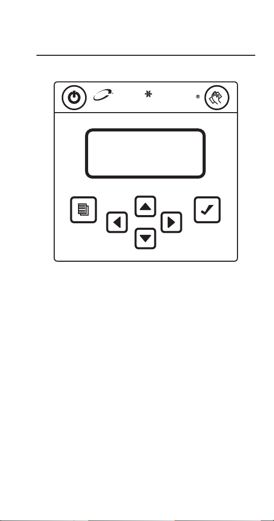
Power Button Cleaning Button
Manitowoc
LCD Display
Navigation Arrows
Menu
Button
Checkmark
Control Panel Features
The control panel offers a series of pressure sensitive
buttons and a four-line interactive display panel.
BUTTONS
Power Button: Powers the ice machine when in the On/
Off Mode. The ice machine can also be programmed
to automatically power on and off in two Energy Saver
modes.
Cleaning Button: Initiates a cleaning cycle. Refer to the
Maintenance section for details.
Part Number 000014794 5/17 55
Page 56

Menu Button: Accesses main menu structure. Moves the
display from the Home Screen, where ice machine status,
alerts and messages are viewed, to the Main Menu, where
machine information and its event log can be accessed,
machine and Energy Saver settings can be adjusted, and
service issues can be addressed.
Left and Right Arrows: The Left arrow moves the display
to the previous screen, allowing the user to “back out”
of programming. Both the Left and Right arrows will
move the cursor (underline) within a line of settings.
NOTE: The Right arrow can also be used on many screens
interchangeably with the checkmark to make a selection.
Up and Down Arrows: Move the highlight [brackets] up
one line or down one line.
Checkmark: Makes a selection and/or moves to the next
screen (or line) and is used like an “enter” button.
DISPLAY PANEL
The LCD display panel is 16 characters wide and four
lines deep. During ice machine operation and cleaning
cycles, the Home screen’s top three lines provide valuable
status information and the fourth line shows alerts and
messages. In programming, four lines of the current
screen are displayed and highlights, arrows, cursor and
selections inform the user of available actions.
56 Part Number 000014794 5/17
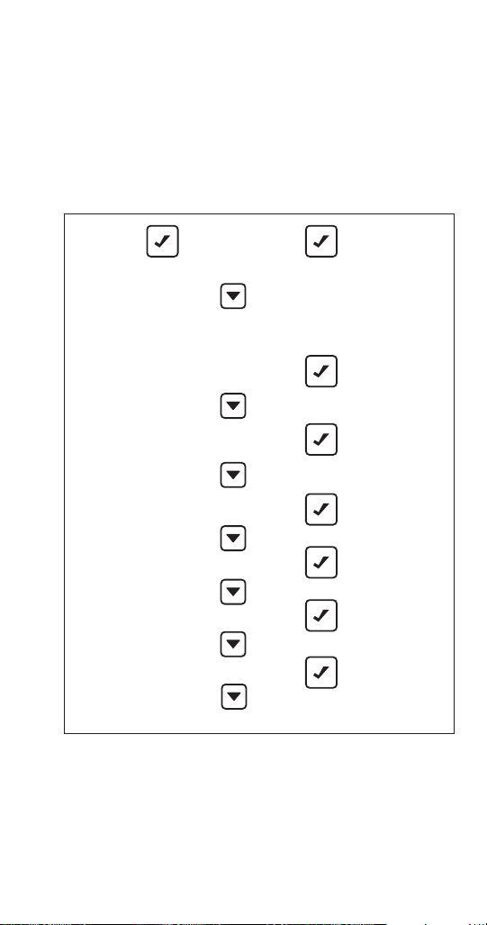
Page 57

Menu Navigation Overview
Menu Button Cleaning ButtonON/OFF Button Timer Initiated
Home Screen
When
Alert
Present
Alerts Messages
Machine
Info
90/70 Capacity
Model Number
Ice Machine Head Serial Number
Condenser Serial Number
Warranty
Install Date
Manufacture Date
Main Software Version
Display Software Version
Exit
Set-up
Password Entry
(Optional)
Language
Time/Date
Time Config
Units
Ice Clarity
LCD Brightness
Password On
Edit Password
Clean Minder
AuCS Run Time
Air Filter
Water Filter
LUMINICE
Ice Bin Sensor
USB Setup
Exit
When
Message
Present
Main Menu
Energy
Saver
AuCS Clean
Clean
Function
Defaults
Defaults
Exit
Ice Program
Water Miser
Statistics
Exit
Press to power ON/OFF
Service
Function
Data History
Real Time Data
Diagnostics
Manual Harvest
Replace Control Board
USB Setup
Event Log
Exit
EXIT
Return to
Home Screen
Press to access cleaning function
Press to access Main Menu
Press to select menu/sub-menu option
Navigate Menus
NOTE: The ice machine will automatically set the
installation date after 100 freeze/harvest cycles.
Part Number 000014794 5/17 57
Page 58
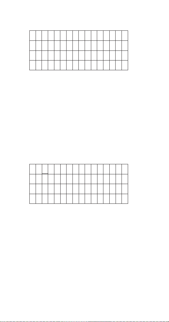
Display Panel Navigation
▼
[Language >]
▼
Time & Date >
Time Config >
Units >
Highlights: Brackets indicate if a line on the screen is
“highlighted” or actionable. Move the brackets from line
to line using the Down or Up arrow. Move the brackets
down from the fourth line to view more of the menu
displayed.
Arrows: Two kinds of arrows give cues to additional
information. “>” symbols show that another screen is
available by pressing Checkmark or > while a line is
highlighted. “▼” and “▲” symbols indicate the limits of
the screen viewed. NOTE: Another cue to the length of a
menu screen is that Exit is the last item.
07 24 10
14:08
Exit >
58 Part Number 000014794 5/17
Page 59

Cursor: A cursor (flashing rectangle) is used within lines
[Mo/Day/Yr ( )]
▼
where actual settings can be adjusted. In these screens,
use the Up and Down arrows to make changes to the
value underlined. Move the cursor from digit to digit
using the Right and Left arrows. Use the Checkmark to
move the cursor down one line. Exit and re-enter the
screen to start again at the top.
▼
Day/Mo/Yr ( )
12 Hour ( )
24 Hour ( )
Selections: When parentheses ( ) appear, they indicate
a selection is available by pressing Checkmark while the
line is highlighted. If the choice is exclusive, selecting it
with the Checkmark will uncheck another selection. That
is, in the above Time Config example, selecting Day/Mo/
Yr will deselect Mo/Day/Yr.
Part Number 000014794 5/17 59
Page 60

Alerts and Messages
When messages and alerts exist, they will be highlighted
and can be selected with the Left arrow. Alerts displayed
will have priority over messages.
Off
On / Off Mode
!
[< ]
For example, if alerts are appearing in the fourth line of
the display:
1. Press the Left arrow. A list of alerts will appear in the
display.
2. Choose the alert you wish to address by moving the
highlight brackets with the Down arrow.
3. Press Checkmark again. A screen appears with the
date, time and total number of times an alert has
occurred. Pressing the Down arrow will list some
possible causes for the alert. At the bottom of the
screen you will be able to clear the alert by pressing
the Checkmark.
4. Return to the Home screen by selecting Exit and
pressing the Checkmark.
60 Part Number 000014794 5/17
Page 61

Main Menu
From the Home screen, press the Menu button to enter
the Main menu, where you can choose to see machine
information, make setup changes, set the Energy Saver
mode, or enter the Service Menu.
Machine Info
Set-Up
Energy Saver
Factory Defaults
Service
Exit
Main Menu
Part Number 000014794 5/17 61
Page 62

Machine Info Menu
From the Main menu, ensure that Machine Info is
highlighted and press the Checkmark to view a list
including capacity, model number, IMH (Ice Machine
Head) serial number, condenser serial number, warranty,
installation date, date of manufacture and software
version. Use the Down arrow to highlight an item and use
the Checkmark to view the information. Press the Left
arrow to return to previous screens.
Machine Info Menu
• 90/70 capacity
• Model #
• Ice Machine Head Serial #
• Condenser Serial #
• Warranty
• Machine
• Evaporator
• Compressor
• Install Date
• Manufacture Date
• Main Control Board Software Version
• Display Software Version
62 Part Number 000014794 5/17
Page 63

Password Entry
A password is not required, although a password can
be turned on to prevent unauthorized control setting
modification. You can use the Factory Default Password
of “1234” or enter a four digit custom pin number of your
choosing.
To turn on the password feature use the following
procedure.
1. Press the Menu button.
2. From the Main menu, use the Down arrow to
highlight setup and press the Right arrow.
3. Use the Down arrow to highlight Password ON and
press the Right arrow.
4. Press the Right arrow again with Enter Passwrd
highlighted and a cursor will flash.
5. Use the Up & Down arrows to enter the factory
password (1, 2, 3, 4). Enter the number 1 in the
flashing cursor (first digit of the factory password).
6. Press the right arrow to move to the next cell and
use the Up & Down arrows to add the number 2.
Repeat this process to add 3 & 4.
7. When the last number is entered press the
Checkmark button to save your entry.
Enter Passwrd
▲
[ ]
Exit >
Part Number 000014794 5/17 63
Page 64

To enter a four digit password of your choosing use
the following procedure.
1. Press the Menu button.
2. From the Main menu, use the Down arrow to
highlight setup and press the Right arrow.
3. Use the Down arrow to select Edit Password and
press the Right arrow.
4. Using the Up & Down arrows, enter the first digit of
the factory password in the flashing icon.
5. Press the right arrow to move to the next cell and
use the Up & Down arrows to add the number 2.
Repeat this process to add 3 & 4.
6. When the last number is entered press the
Checkmark button.
7. Follow steps 4 & 5 and enter your 4 digit password.
8. When the last number is entered press the
Checkmark button to save your entry.
64 Part Number 000014794 5/17
Page 65

RESET PASSWORD TO FACTORY DEFAULTS
The password can be reset to the factory defaults when
required. The default factory password is 1234.
The entire setup can be reset to the factory defaults.
1. From the Set-Up menu, use the Down arrow to
highlight Fact Deflts.
2. Press the Checkmark two times to reset the ice
machine. The display will return to the Set-Up menu.
Setting Default
Language English
Time Configuration Mo/Day/Yr/24 Hour
Units Fahrenheit/Lbs/Gallons
Ice Clarity Off
LCD Brightness Level 2
Password Off - Enter Password
Default Password = 1234
Edit Password Off - Edit Password
Clean Minder Off
AuCS RunTime Off
Air Filter Minder Off
Water Filter Minder Auto
LuminIce Bulb Minder No
Ice Bin Sensor None
Part Number 000014794 5/17 65
Page 66

Set-Up Menu
Set-Up
Time Configuration
Exit
From the Main menu, use the Down arrow to navigate to
Set-Up and press the Checkmark. Select and customize
machine settings on this menu. Press the Left arrow to
return to previous screens.
Language
Time & Date
Units
Ice Clarity
LCD Bright
Password On
Edit Password
Clean Minder
AuCS RunTime
Air Filter
Water Filter
LUMINICE
Ice Bin Sensor
USB Setup
Set-Up Menu
66 Part Number 000014794 5/17
Page 67

LANGUAGE
[Mo/Day/Yr ( )]
▼
1. From the Set-Up menu, use the Down arrow to
highlight Language.
2. Press the Checkmark. You can choose to view
the display in a language other than English,
by highlighting your choice and pressing the
Checkmark. Selecting one language will deselect the
others.
3. When the check reflects your preference, use the
Down arrow to navigate to Exit and press the
Checkmark. The display will return to the Set-Up
menu.
TIME & DATE
When the ice machine is installed, the correct time and
date needs to be set for its location.
▼
Day/Mo/Yr ( )
12 Hour ( )
24 Hour ( )
Set the Time and Date
1. Press the Menu button.
2. Press the Down arrow until Set-Up is highlighted
[bracketed].
3. Press the Checkmark. The Set-Up menu will be
displayed and Time & Date will be highlighted
[bracketed].
Part Number 000014794 5/17 67
Page 68

4. Press the Checkmark. The date will appear on the
first line of the display (Mo/Day/Yr) and the time will
appear on the second line (24 Hour). The month will
have a blinking cursor.
5. Using the Up or Down arrow, adjust the month, if
necessary.
6. When the correct month appears, use the Right
arrow to move the blinking cursor to day.
7. Using the Up or Down arrow, adjust the day, if
necessary.
8. When the correct day appears, use the Right arrow
to move the blinking cursor to year.
9. Using the Up or Down arrow, adjust the year, if
necessary.
10. When the correct year appears, press the Checkmark.
Use the Right arrow to move the blinking cursor to
hour.
11. Using the Up or Down arrow, adjust the hour, if
necessary.
12. When the correct hour appears, use the Right arrow
to move the blinking cursor to minutes.
13. Using the Up or Down arrow, adjust the minutes, if
necessary.
14. When the correct minutes appear, press the
Checkmark twice.
68 Part Number 000014794 5/17
Page 69

TIME CONFIGURATION
1. From the Set-Up menu, use the Down arrow to
highlight Time Config.
2. Press the Checkmark. On this screen, you can choose
whether the date will be displayed as Mo/Day/Yr or
Day/Mo/Yr by highlighting your choice and pressing
the Checkmark. Selecting one will deselect the other.
3. You can also choose whether the time will be
displayed as 12 Hour or 24 Hour by highlighting your
choice and pressing the Checkmark. Selecting one
will deselect the other.
4. When the two checks reflect your preference, use
the Down arrow to navigate to Exit and press the
Checkmark. The display will return to the Set-Up
menu.
UNITS
1. From the Set-Up menu, use the Down arrow to
highlight Units.
2. Press the Checkmark. On this screen, you can choose
whether the ice machine will display measurements
in Celsius or Fahrenheit, kilograms or pounds, and
gallons or liters by highlighting your choice of each
pair and pressing the Checkmark. Selecting one
of each pair will deselect the other. Make sure to
navigate with the Down arrow to make all three
choices.
3. When the three checks reflect your preferences, use
the Down arrow to navigate to Exit and press the
Checkmark. The display will return to the Set-Up
menu.
Part Number 000014794 5/17 69
Page 70

ICE CLARITY
In areas with poor potable water quality, the ice machine
may produce cloudier ice. Setting Ice Clarity to ON will
add additional water during the freeze cycle to dilute the
water that contains a high content of dissolved solids in
the water trough. This feature decreases production and
increases water usage. A water filter is recommended to
produce the highest quality ice while maintaining the
least expensive mode of operation.
1. From the Set-Up menu, use the Down arrow to
highlight Ice Clarity.
2. Press the Checkmark. On this screen, you can
choose to turn the ice clarity feature ON or OFF
by highlighting your choice and pressing the
Checkmark. Selecting one will deselect the other.
3. When the check reflects your preference, use the
Down arrow to navigate to Exit and press the
Checkmark. The display will return to the Set-Up
menu.
LCD BRIGHTNESS
Here, the brightness of the LCD display can be adjusted.
1. From the Set-Up menu, use the Down arrow to
highlight LCD Bright.
2. Press the Checkmark. You will see one of four
checkmarks indicating the brightness levels of the
display. Level 1 is one checkmark, level 2 is two
checkmarks, Level 3 is three checkmarks, etc.
3. Use the Up and Down arrows to select your
preference.
4. When the checkmarks reflect your preference, press
the Checkmark. The display will return to the Set-Up
menu.
70 Part Number 000014794 5/17
Page 71

PASSWORD ON
A password can be added to prevent unauthorized
changes to ice machine settings.
1. From the Set-Up menu, use the Down arrow to
highlight Password On.
2. Enter the password and press the Checkmark.
3. Press the Left arrow to return to previous screens
and to the Set-Up menu.
EDIT PASSWORD
The password can be changed on this screen.
1. From the Set-Up menu, use the Down arrow to
highlight Edit Password.
2. Press the Checkmark and confirm current password.
3. Enter new password and press the Checkmark.
4. Press the Left arrow to return to previous screens
and to the Set-Up menu.
CLEAN MINDER
Clean Minder is a feature that displays a cleaning
reminder at a set time interval.
1. From the Set-Up menu, use the Down arrow to
highlight Clean Minder.
2. Press the Checkmark. On this screen, you can choose
to turn the reminder ON or OFF by highlighting your
choice and pressing the Checkmark. Selecting one
will deselect the other.
3. You can also choose the time interval from this
screen by highlighting Set Interval and pressing the
Checkmark.
4. Press the Left arrow to return to previous screens
and to the Set-Up menu.
Part Number 000014794 5/17 71
Page 72

IAUCS RUNTIME
Automatic Cleaning System is an optional accessory and
will perform a cleaning cycle at a set time interval.
1. From the Set-Up menu, use the Down arrow to
highlight AuCS RunTime.
2. Press the Checkmark. On this screen, you can choose
to turn the feature ON or OFF by highlighting your
choice and pressing the Checkmark. Selecting one
will deselect the other.
3. You can also choose the time interval from this
screen by highlighting Set Interval and pressing the
Checkmark.
4. Press the Left arrow to return to previous screens
and to the Set-Up menu.
AIR FILTER
The ice machine has a feature that displays a clean air
filter reminder at a set time interval.
1. From the Set-Up menu, use the Down arrow to
highlight Air Filter.
2. Press the Checkmark. On this screen, you can choose
to turn the reminder to AUTO or OFF by highlighting
your choice and pressing the Checkmark. Selecting
one will deselect the other.
3. You can also choose the time interval from this
screen by highlighting Set Interval and pressing the
Checkmark.
4. Press the Left arrow to return to previous screens
and to the Set-Up menu.
72 Part Number 000014794 5/17
Page 73

WATER FILTER
The ice machine has a feature that displays a replace
water filter reminder at a set time interval.
1. From the Set-Up menu, use the Down arrow to
highlight Water Filter.
2. Press the Checkmark. You can record the filter
type on this screen by highlighting Filter Type and
pressing the Checkmark. After making your selection
(AR10,000, AR20,000, AR40,000), scroll down to exit
and press the Checkmark.
3. You can also choose to turn the reminder to AUTO,
NONE or OFF by highlighting your choice and
pressing the Checkmark. Selecting one will deselect
the other.
• Selecting Auto sets the reminder based on water
usage for the selected filter.
• Selecting None will turn off the reminder.
• Selecting Off sets the timer to the selected
reminder time (2 weeks to 6 months).
4. You can further choose the time interval from this
screen by highlighting Set Interval and pressing the
Checkmark.
5. Press the Left arrow to return to previous screens
and to the Set-Up menu.
Part Number 000014794 5/17 73
Page 74

LUMINICE® REMINDER
The LuminIce® growth inhibitor recirculates the air in the
ice machine foodzone over a UV bulb. This process will
inhibit the growth of common micro-organisms on all
exposed foodzone surfaces.
The Bulb Minder is a feature that displays a reminder to
change its bulb every 12 months.
1. From the Set-Up menu, use the Down arrow to
highlight LuminIce Minder.
2. Press the Checkmark. On this screen, you can choose
to turn the reminder to AUTO or OFF by highlighting
your choice and pressing the Checkmark. Selecting
one will deselect the other.
3. When the check reflects your preference, use the
Down arrow to navigate to Exit and press the
Checkmark. The display will return to the Set-Up
menu.
74 Part Number 000014794 5/17
Page 75

ICE BIN LEVEL SENSOR
Ice bin sensor is an optional accessory that allows the ice
level in the bin to be set to one of three different levels.
The bin level can be set seasonally to match usage, which
results in lower energy costs and fresher ice.
1. From the Set-Up menu, use the Down arrow to
highlight Ice Bin Sensor.
2. Press the Checkmark. On this screen, you can
choose to set the ice level to Low, Medium or
High by highlighting your choice and pressing the
Checkmark. Selecting one will deselect the other.
When the check reflects your preference, use the Down
arrow to navigate to Exit and press the Checkmark. The
display will return to the Set-Up menu.
USB SETUP
Refer to “Upgrading Firmware with a Flash Drive” and
“Exporting Data to a Flash Drive” for more information
on this setting. Flash drives must be correctly sized and
formatted - 2 gigabytes or smaller, Fat 32 file system, 512
allocation units - Refer to page 92 for full specification
and formatting details.
FACTORY DEFAULTS
The entire setup can be reset to factory defaults listed on
page 65.
1. From the Set-Up menu, use the Down arrow to
highlight Fact Default.
2. Press the Checkmark two times to reset the ice
machine. The display will return to the Set-Up menu.
Part Number 000014794 5/17 75
Page 76

Energy Saver Menu
From the Main menu, use the Down arrow to navigate to
Energy Saver and press the Checkmark. Set up an energy
saving ice program, enable the Water Miser and view
usage statistics from this menu. Press the Left arrow to
return to previous screens.
Energy Saver Ice Program
Water Miser
Statistics
Exit
Energy Saver Menu
76 Part Number 000014794 5/17
Page 77

ICE PROGRAM
To save energy and water, the ice machine can be
programmed to only power up during time periods
that the ice will be used or when the bin level is being
depleted by heavy use.
1. In the Energy Saver menu, ensure that Ice Program is
highlighted.
2. Press the Checkmark. On this screen, you can choose
to turn on the time program (Time Prog) bin level
program (Bin Level) or ice usage program (Ice
Program) by highlighting your choice and pressing
the Checkmark. Selecting one will deselect the other.
If one of them is selected and you wish to turn both
off, highlight the choice and press Checkmark again.
3. If none of the programs are selected, highlighting
Settings and pressing the Checkmark will select the
times, bin level or pounds of ice per day. If one of the
programs is selected, highlight Settings and press
the Checkmark to choose the times or bin levels.
NOTE: For details on how to use the cursor for the
time program, refer to “Display Panel Navigation” in
this section.
4. Select Exit to return to previous screens and again to
the Energy Saver menu.
Part Number 000014794 5/17 77
Page 78

WATER MISER
Water Miser is a feature that depending on water quality
can reduce water usage by eliminating flush cycles.
1. From the Energy Saver menu, use the Down arrow to
highlight Water Miser.
2. Press the Checkmark. On this screen, you can choose
to turn the Water Miser ON or OFF by highlighting
your choice and pressing the Checkmark. Selecting
one will deselect the other.
3. Use the Down arrow to navigate to Exit and press the
Checkmark to return to the Energy Saver menu.
STATISTICS
1. From the Energy Saver menu, use the Down arrow to
highlight Statistics.
2. Press the Checkmark. Choose to view ice usage, or
potable water and energy statistics by highlighting
your choice and pressing the Checkmark.
3. Press the Left arrow to return to previous screens
and to the Energy Saver menu.
78 Part Number 000014794 5/17
Page 79
Service Menu
Control Board
Hrvst Started
Exit
From the Main menu, use the Down arrow to navigate to
Service and press the Checkmark. This menu is intended
for the use of trained service personnel. Below is an
overview of the service menu. The following pages list the
navigation options available by drilling into the menus
with the Right arrow.
Service Data History 00000000
00000000
00000000
00000000
00000000
00000000
Lifetime
Exit
RealTime Data Time & Temp
Inputs
Outputs
Exit
Diagnostics
Temp Sensors
Inputs
Exit
Man Harvest
Exit
Repl Cntl Bd Manual Setup
USB Setup
Exit
USB Setup USB Stick
Exit
Event Log View ELog
Clear ELog
Exit
Part Number 000014794 5/17 79
Page 80

Histor
Current Day
Current Day -1
Current Day -2
Current Day -3
Current Day -4
Current Day -5
Lifetim
Event Log
View E Log
Clear E Log
Service
USB Setup
Repl Cnt Bd
Harvest
Manual
Diagnostics
Data
Real Time
y
Data
USB Stick
Setup
Manual
USB Setup
Started
Harvest
Board
Control
Temp
Time &
Export ALL
Export Setup
Download Frm
Download Cnf
Input
Temp
Sensors
Inputs
Outputs
e
80 Part Number 000014794 5/17
Page 81

DATA HISTORY
Press the Checkmark with Data History highlighted to
view a list of eight-digit dates (Current, Current + 1 ...
Current + 5), along with Lifetime (be sure to use the
Down arrow to reveal all the available information).
For each of the dates, use the Checkmark to view:
• Minimum Freeze
• Maximum Freeze
• Minimum Harvest
• Maximum Harvest
• Maximum Temperature Delta T3 - T4
• Delta
• T3
• T4
• RunTime
• Ice Production
• Cycle Count
• Potable Water
• Clean Cycles
• Exit
For Lifetime, use the Checkmark to view:
• Install Date
• Control Board Replacement Date
• Control Board DOM (Date Of Manufacture)
• RunTime
• Cycle Count
• Potable Water
• Clean Cycles
• Exit
Part Number 000014794 5/17 81
Page 82

REAL TIME DATA
Press the Checkmark with Real Time Data highlighted
to get readings on Time & Temp, Inputs and Outputs (be
sure to use the Down arrow to reveal all the available
information).
Use the Checkmark to view:
Time and Temperature
• Status Off/On - Displays stage of cycle
• Time
• T1 Thermistor Temperature
• T2 Thermistor Temperature
• T3 Thermistor Temperature
• T4 Thermistor Temperature
• T3 & T4 Delta Temperature
• 100 hz
• 120 hz
• Exit
Inputs
• Status Off/On - Displays stage of cycle
• Curtain Switch 1
• Curtain Switch 2
• LPCO Switch
• HPCO Switch
• Bin Level - Low (Optional Bin Level Probe) Status
• Bin Level - Medium (Optional Bin Level Probe) Status
• Bin Level High (Optional Bin Level Probe) Status
• Sensing Ice No/Yes
• Water Level Low No/Yes
• Water Level High No/Yes
• Exit
82 Part Number 000014794 5/17
Page 83

Outputs
• Status Off/On - Displays stage of cycle
• Water Pump Off/On
• Hot Gas Valve 1 Off/On
• Hot Gas Valve 2 Off/On
• Air Pump Off/On
• Water Valve Off/On
• Dump Valve Off/On
• Compressor Control Off/On
• AuCS Relay Off/On
• Ionic Cln Off/On
• Exit
Part Number 000014794 5/17 83
Page 84

DIAGNOSTICS
Press the Checkmark with Diagnostics highlighted to
enter screens where you can run diagnostics on the
control board, sensors and switches.
Control Board
• Self Check
• Enable Relays
• Exit
Temperature Sensors
• T1 Thermistor Temperature
• T2 Thermistor Temperature
• T3 Thermistor Temperature
• T4 Thermistor Temperature
• Exit
Inputs
• Curtain Switch 1 Closed/Open
• Curtain Switch 2 Closed/Open
• LPCO Switch Closed/Open
• HPCO Switch Closed/Open
• Bin Level - Low (Optional Bin Level Probe) Closed/
Open
• Bin Level - Medium (Optional Bin Level Probe) Closed/
Open
• Bin Level - High (Optional Bin Level Probe) Closed/
Open
• Sensing Ice No/Yes
• Water Level Low No/Yes
• Water Level High No/Yes
• Exit
84 Part Number 000014794 5/17
Page 85

MANUAL HARVEST
Press the Checkmark with Manual Harvest highlighted to
initiate a manual harvest.
• Manual Harvest
• Harvest Started
• Exit
REPLACE CONTROL BOARD
Press the Checkmark with Replace Control Board
highlighted to program the replacement control board.
The data can copied from the defective control board
(refer to “Exporting Data to a Flash Drive” on page 96),
or entered manually through the Indigo interface.
• Manual Setup
• Board Install Date
• Input Model Number
• Input Serial Number
• Condenser/condensing unit serial number
• USB Setup
• Insert Drive
• Press Checkmark and wait for completion
• Exit
USB SETUP
• USB Stick
• Download Firmware
Insert drive and wait for completion
• Download Configuration
Insert drive and wait for completion
• Export All
Insert drive and wait for completion
• Export Setup
Insert drive and wait for completion
• Exit
Part Number 000014794 5/17 85
Page 86
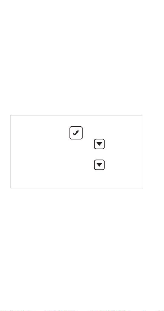
EVENT LOG MENU
From the Service menu, use the Down arrow to navigate
to Event Log and press the Checkmark.
Ensure View ELog is highlighted and press the Checkmark
to see the first event code, when it occurred and how
many times. Use the Down arrow to view information on
subsequent event codes. For more information on event
codes, see “Service Menu”. Use the Left arrow to return to
the Event Log menu.
To clear the event log: In the Event Log Menu, use the
Down arrow to highlight Clear ELog and press the
Checkmark. Press the Left arrow to return to previous
screens.
Event Log View ELog
Clear ELog
Exit
Event Log Menu
86 Part Number 000014794 5/17
Page 87

EVENT LOG
Refer to the following table for Event Code descriptions.
Code Description
E01 Long Freeze Cycle
E02 Long Harvest Cycle
E03 Input Power Loss
E04 High Condenser Temperature
E05 High Pressure Control Opened
E06 Spare
E07 Starving TXV Single Evaporator or Low On Charge
E08 TXV Fault Single or Dual Circuit Evaporators
E09 Flooding Evaporator Fault Single Evaporator, Single
Circuit
E10 Flooding Evaporator Fault Dual TXV, Dual Circuit
E11 Refrigeration Fault
E12 Curtain Switch Fault - E Board = Open more than
12hours, G Board after Revision 4.017 = Open more
than 24 hours
E13 Spare
E14 Spare
E15 Fan Cycle Control Fault - Lo Liquid Line Temperature
E16 Remote Condensing Unit Fault (ICVD Only)
E17 Spare
E18 Spare
E19 Ice Thickness Probe Fault
E20 Water System Fault
E21 T1 Temperature Sensor Issue
E22 T2 Temperature Sensor Issue
E23 T3 Temperature Sensor Issue
E24 T4 Temperature Sensor Issue
E25 Bin Level Probe Low Sensor Fault
E26 Bin Level Probe Medium Sensor Fault
E27 Bin Level Probe High Sensor Fault
E28 AuCS
E29 USB Communication Fault
E30 USB Download Fault
E31 Safe Mode
E32 RS485 Communication Fault
E33 KeyBoard Fault
E34 Display Fault
Part Number 000014794 5/17 87
Page 88

E-L
g
p
y
p
g
y
g
ht on board
p
p
p
p
Starving TX
TXV Faul
Detail Event Log Service Definition
average of first 6 minutes of freeze cycle (T2), is less than 1.05°F
average of first 6 minutes of freeze cycle (T2), is less than 1.05°F
cles = shut down and flash the SL#1 li
.
ower-u
ower on
the loss of
Average compressor discharge line temperature last 6 seconds of Prechill +50°F (T1) compared to
6 consecutive 60 Minute Freeze c
3 consecutive - 3.5 Minute Harvests logs SL#2 in memory, but runs until 500 long harvest cycles occur.
When power is interrupted to the ice machine the control board will log the event in the ELOG and
stam
Definition
1). Liquid Line Temperature too High for Self-contained Air Cooled Ice machine = Air Cooled
The high pressure cutout switch (HPCO) opened 3 times in 4 hour period
Condenser Fault
2). Liquid Line Temperature too High for Self-contained Water Cooled ice machine = Water Cooled
Condenser Fault
10 consecutive occurrences where the Difference of the Av erage evaporator inlet (T3) and outlet (T4)
tion
Long Freeze
Long Harvest
Power Supply (Event Log only -
Air Condenser High temp, or
water Condenser High
Freeze
Lon
Long Harvest
E02
No Alert)
Power Loss
E03
Text Error Descri
la
Dis
o
E01
Event Log Detail
88 Part Number 000014794 5/17
High Pressure Cutout (HPC)
temperature
G Board Rev 4.017 - Alert only
Wtr Cnd Fault
Hi Cnd Temp or
E04
Starving Evaporator for single
after 10 consecutive trips
HPC Fault
E05
E06Spare
is greater than 12°F in the last 1 minute of the freeze cycle (ELOG-E07)
10 consecutive occurrences where the Difference of the Av erage evaporator inlet (T3) and outlet (T4)
is greater than 12°F in the last 1 minute of the freeze cycle (ELOG-E07)
Air/Water Only
TXV malfunction in dual circuit/
G Board Rev 4.017 -
Event Log only no alert
TXV or low on charge
V
E07
Flooding evaporator for single
single evaps (TXV Fault)
t
E08
Average compressor discharge line temperature last 6 seconds of Prechill +50°F (T1) compared to
evap)
circuit single evaporator (flooding
Flooding evaporator for dual TXV
dual circuit / single evaporator
(Flooding Evap)
Flood Evap 1
Flood Evap 2
E09
E10
Page 89

y
p
y
g
y
red Frequencies is out of the appropriate range (Probe unplugged or proble
p
)
4) Low or High water probe satisfied at end of freeze cycle.
G Board Rev 4.017 = 24 hrs - E Board = 12 hrs
E-L
g
p
y
p
Detail Event Log Service Definition
G Board Rev 4.017 - Event Log only no alert
cle.
m with
G Board Rev 4.017 - Event Log only no alert
en or curtain is off.
The compressor discharge temperature did not increase by at least 10 F, and the ev aporator
The ice machine is set to ice making and remains in bin full condition for more than 24 hours.
until 2 minutes into the Freeze c
The curtain switch is o
temperature did not decreased by at least 10 F - Measured from Refrigeration Start up or Prechill
Definition
tion
Air & Water-cooled Only
Refrigeration System (Refrig
Curtain Switch open for more
Fault)
than 24 hours (Curtain Fault)
G Board Rev 4.017 - Event Log only no alert
cle.
G Board Rev 4.017 - Event Log only no alert
cle.
the freeze c
If the liquid line temperature drops below 60 F for any period exceeding continuous 1 minute during the
the freeze c
If the liquid line temperature drops below 40 F, or exceeds 140 F for more than 1 continuous minute
durin
G Board Rev 4.017 - Event Log only no alert
.
hone
micro
The monito
Any of the following:
1) Sensing high water probe and not low water probe = Water fault.
2) The Evaporator outlet temperature is less than -10°F 6.5 to 7.5 Minutes into freeze.
3) The Low Water probe is satisfied at the end of harvest.
amb
Low amb control fault durring low
Remote Condenser Fault
ICVD Condensing Unit only
Ice Probe (ITP)
Water System Fault
Text Error Descri
la
Refig Fault
Dis
o
Curtain Fault
E11
E12
Low Liq Temp
Rmt Cnd Fault
E13Spare
E14Spare
E15
E16
ITP Fault
WTR Fault
E17Spare
E18Spare
E19
E20
Part Number 000014794 5/17 89
Page 90
AUCS board and if the AUCS is not connected it will signal an Ev
p
USB DNL
USB Download error related to USB drive or a defective USB driv
allows the ice machine to operate for a period of time in the event of a WLP or ITP
sensor failure. The controller allows the machine to operate based on historical information
collected and model data information stored in the controllers memory.
E-L
g
p
y
p
Detail Event Log Service Definition
ent “AUCS”. This will be cleared
e
ort or defective USB drive
Each thermistor reading is monitored continuously using six second average values. During Pre-chill
a thermistor had a six second average thermistor values fall outside of the valid temperature range.
Definition
Each thermistor reading is monitored continuously using six second average values. A
thermistor had a six second average value outside of the valid range for more than 10 continous
minutes
tion
T1 Sensor
T2 Sensor
T3 Sensor
T4 Sensor
Bin Low Sens
Bin Med Sens
as soon as the hardware is detected.
When the AUCS clean option is selected from the menu, the control checks for the presence of the
Bin Hi Sens
USB Communication error, no USB drive in
AUCS (Aucs not Present) (Event
Log only - No alarm)
USB Comm (Event Log only - No
USB download error (dlnd) Event
Alarm)
Log only - No alarm)
D
Text Error Descri
la
T1 Fault
T2 Fault
T3 Fault
T4 Fault
Bin Prb Fault
Bin Prb Fault
Bin Prb Fault
AUCS
E28
USB COMM
E29
E30
Dis
o
90 Part Number 000014794 5/17
E23
E24
E25
E21
E22
E27
E26
Safe mode
Safe Mode (Event Log only - No
alarm)
Safe Mode
E31
Page 91

E32
RS485 COMM
Event Log only - No Alarm
The Key board is not plugged into the control board or is faulty.
The device plugged into the RS485 port is not communicating between the control board
and gateway.
E33
KEYBOARD
Event Log only - No Alarm
E34
DISPLAY
Event Log only - No Alarm
The Key board is not plugged into the control board or is faulty.
E-Lo
g
Dis
p
la
y
Text
Error Descri
p
tion
Definition
Detail Event Log Service Definition
Part Number 000014794 5/17 91
Page 92

USB FLASH DRIVE SPECIFICATIONS AND FORMATTING
Updating firmware on Indigo™ model ice machines
requires a properly formatted 2 GB or smaller USB flash
drive. All USB flash drives must be formatted before use
to remove any software programs or files currently on the
flash drive.
USB Flash Drive Specifications:
• USB 2 Version
• 2 GB or less capacity
• Fat32 File System
• 512 MB File Allocation Unit
USB Flash Drive Formatting:
Procedure to format a USB flash drive varies with
operating system software.
Windows 7 or Windows Vista Computers:
1. Insert USB flash drive; your computer may indicate:
• “Found New Hardware” follow the prompts to
install the USB flash drive
• USB flash drive may auto play - Close auto play
window
2. Press Windows Key and E key simultaneously to
access windows explorer.
3. Right click on your USB Flash Drive.
4. Left click on “Format”.
5. Verify or select the settings below:
• USB flash drive capacity - 2 GB or less
• File System - Fat32
• Allocation Unit Size - Must be 512 MB
• Volume Label is Optional - Rename if desired
• Deselect “Perform A Quick Format” (no
checkmark)
6. Left click on “Start” - You will receive a warning “Formatting will remove all data” left click “OK”. A
“Format Complete” box will display when formatting
is finished. Close the pop up and windows explorer.
92 Part Number 000014794 5/17
Page 93

Windows XP Computers:
1. Insert USB flash drive; your computer may indicate:
• “Found New Hardware” follow the prompts to
install the USB flash drive
• USB flash drive may auto launch - Close auto
launch window.
2. To access Disk Management:
• Left click on the Windows Start Button
• Left click on “Run”
• Type compmgmt.msc and left click on “OK”
• Left click on “Disk Management”.
3. Verify USB flash drive capacity is 2 GB or less
4. Right click on the USB flash drive, then left click on
“Format” from the drop down list.
5. Verify or select the settings below:
• Volume Label is Optional - Rename if desired
• File System - Fat32
• Allocation Unit Size must be 512 MB
• Deselect “Perform A Quick Format” (no
checkmark)
6. Left click on “OK” you will receive a warning “Formatting will remove all data” left click on “OK”,
wait until formatting is complete and “status”
indicates “Healthy”, then close the disk management
window.
Part Number 000014794 5/17 93
Page 94

UPGRADING FIRMWARE WITH A FLASH DRIVE
Important
The flash drive must be formatted before using, All
files and software on the flash drive are removed
during the formatting process. Refer to page 92
USB Flash Drive Specifications and Formatting.
1. Drag and drop the files from website or email onto a
flash drive.
2. Ensure that the ice machine’s power is on.
3. Press the Menu button.
4. Press the Down arrow until Service is highlighted.
5. Press the Checkmark. The Service menu will be
displayed.
USB Setup USB Stick Download Frm
6. Press the Down arrow until USB Setup is highlighted.
7. Press the Checkmark. USB Stick will appear
highlighted.
8. Press the Checkmark again. A submenu with
Download Frm (Download Firmware) appears.
9. Ensure that Download Frm is highlighted and press
the Checkmark. A display of instructions will appear.
94 Part Number 000014794 5/17
Page 95

USB Connector
Bin
Display Light
Micro Light
Clean Light
Harvest Light
SL-1 Light
SL-2 Light
Transformer
Fuse
Thermistors
Display
RS485
Bin LED
LuminIce
Water
Level
Probe
Bin Switches
T1
T2
T3
T4
Ice Thickness Probe Light
Thermostat USB
Dump Valve
Left Bin Switch Light
Right Bin Switch Light
Water Level Probe Light
RT Harvest
Compressor
Battery
LT Harvest
Relay Lights
Pump
Control Board
10. Follow the on-screen instructions:
A. Insert Drive (Insert the flash drive into the USB
port on the ice machine’s control board.)
B. Press Check (Press the Checkmark.) Do not
remove flash drive, touch display buttons or
remove power while firmware is updating.
C. The display will return to the home screen in
the off mode.
11. Reboot control board by removing power for 15
seconds and reapplying power.
12. Verify the new firmware version loaded by
navigating to Menu/Machine information/Main
Software Version and verify the firmware version
number.
Part Number 000014794 5/17 95
Page 96

EXPORTING DATA TO A FLASH DRIVE
Data can be copied from the control board memory
to a flash drive and used to transfer setup and/or cycle
data to a replacement control board or to transfer setup
information to multiple ice machines. Data may also be
requested by service department personnel for analysis
or as an aid to troubleshooting. The data files are small
and can be attached to an email.
Important
The flash drive must be formatted before using, Refer
to page 92 USB Flash Drive Specifications and
Formatting. All files and data are deleted during the
formatting process.
1. Ensure that the ice machine’s power is on.
2. Press the Menu button.
3. Press the Down arrow until Service is highlighted.
4. Press the Checkmark. The Service menu will be
displayed.
USB Setup USB Stick Export All
5. Press the Down arrow until USB Setup is highlighted.
96 Part Number 000014794 5/17
Page 97

6. Press the Checkmark. USB Stick will appear
highlighted.Press the Checkmark again. A submenu
with Export ALL and Export Setup appears.
NOTE:
There are four files stored in ice machine memory:
• Asset Data - ASDATAoo.CSV
• Operating Data - OPDATAoo.CSV
• Real Time Data - RTDATAoo.CSV
• Ice Machine Settings - Settinoo.CSV
Select only “Ice Machine Settings” file when multiple
machines will be programmed with the same user
specified settings. Select “Export All” if you are installing a
replacement board.
7. Highlight Export ALL or Export Setup, depending
on your requirements, and press the Checkmark. A
display of instructions will appear.
8. Follow these on-screen instructions to:
A. Insert Drive (Insert the flash drive into the USB
port on the ice machine’s control board.)
B. Press Check (Press the Checkmark.)
C. Wait For Comp (Wait approximately 5 to 10
minutes for the download to complete.)
D. Depending on software version either Export
Complete, Success or the Home screen will
appear.
Part Number 000014794 5/17 97
Page 98

Operational Checks
GENERAL
Manitowoc ice machines are factory-operated and
adjusted before shipment. Normally, new installations do
not require any adjustment.
To ensure proper operation, always follow the
Operational Checks:
• when starting the ice machine for the first time
• after a prolonged out of service period
• after cleaning and sanitizing
NOTE: Routine adjustments and maintenance procedures
are not covered by the warranty.
Important
Refrigeration compressors must be operated for a
minimum break in period of 24 hours before full ice
production will be reached.
98 Part Number 000014794 5/17
Page 99

ICE THICKNESS CHECK
The ice thickness probe is factory-set to maintain the ice
bridge thickness at 1/8 in. (3 mm).
NOTE: Make sure the water curtain/splash shields are in
place when performing this check. It prevents water from
splashing out of the water trough. Remove the curtain to
make an adjustment, then replace immediately after the
adjustment is made.
1. Inspect the bridge connecting the cubes. It should
be about 1/8 in. (3 mm) thick.
2. If adjustment is necessary, turn the ice thickness
probe adjustment screw clockwise to increase
bridge thickness or counterclockwise to decrease
bridge thickness. Set a 9/32” gap between the ice
thickness probe and evaporator as a starting point.
Then adjust to achieve 1/8” ice thickness.
3. Make sure the ice thickness probe wire and the
bracket do not restrict movement of the probe.
1/8" (3 mm)
ICE BRIDGE THICKNESS
PLACE 9/32" (7MM) DRILL BIT
HERE TO SET INITIAL GAP
Ice Thickness Check
NOTE: Turning the adjustment 1/3 of a turn will change
the ice thickness about 1/16” (1.5 mm).
Part Number 000014794 5/17 99
Page 100

Control Board Timers
The control board has the following non-adjustable
timers:
• The ice machine is locked into the freeze cycle for 6
minutes before a harvest cycle can be initiated. This
can be overridden by initiating a manual harvest.
Refer to “Manual Harvest” on page 85
• The maximum freeze time is 35 minutes at which
time the control board automatically initiates a
harvest sequence.
Firmware 5.009 or earlier - Maximum freeze time
is 60 minutes at which time the control board
automatically initiates a harvest sequence.
• The maximum harvest time is 7 minutes, the control
board will preform a water thaw cycle and then
return the ice machine to the freeze cycle.
Firmware 5.009 or earlier - The maximum harvest
time is 3.5 minutes. The control board automatically
initiates a freeze sequence when this time is
exceeded.
• The maximum water fill is 12 minutes.
100 Part Number 000014794 5/17
 Loading...