

Page 1
Manitowoc
EC Models
Technician’s Handbook
This manual is updated as new information and models
are released. Visit our website for the latest manual.
America’s #1 Selling Ice Machine
Manitowoc Ice P/N 80-1520-3 9/10
www.manitowocice.com
Page 2

Page 3
Safety Notices
!
Warning
!
Caution
When using or servicing these Ice Machines, be sure
to pay close attention to the safety notices in this
handbook. Disregarding the notices may lead to
serious injury and/or damage to the ice machine.
Throughout this handbook, you will see the following
types of safety notices:
Text in a Warning box alerts you to a potential
personal injury situation. Be sure to read the
Warning statement before proceeding, and work
carefully.
Text in a Caution box alerts you to a situation in
which you could damage the ice machine. Be sure
to read the Caution statement before proceeding,
and work carefully.
Page 4

Procedural Notices
Important
When using or servicing these Ice Machines, be sure
to read the procedural notices in this handbook. These
notices supply helpful information that may assist you
as you work.
Throughout this handbook, you will see the following
types of procedural notices:
Text in an Important box provides you with
information that may help you perform a procedure
more efficiently . Disregarding this information will not
cause damage or injury, but may slow you down as
you work.
NOTE: Text set off as a Note provides you with
simple, but useful extra information about the
procedure you are performing.
Page 5
Read These Before Proceeding:
!
Caution
Important
!
Warning
!
Warning
Proper installation, care and maintenance are
essential for maximum ice production and trouble
free operation of your Manitowoc Ice Machine. If you
encounter problems not covered by this manual, do
not proceed, contact Manitowoc Ice, Inc. We will be
happy to provide assistance.
Routine adjustments and maintenance procedures
outlined in this manual are not covered by the
warranty.
We reserve the right to make product improvements at
any time. Specifications and design are subject to
change without notice.
PERSONAL INJURY POTENTIAL
Do not operate equipment that has b een misused,
abused, neglected, damaged, or altered/modified
from that of original manufactured specifications.
POTENTIAL PERSONAL INJURY SITUATION
This ice machine contains refrigerant charge.
Installation and Servicing must be performed by a
properly trained refrigeration technician aware of the
Dangers of dealing with refrigerant charged
equipment.
Page 6

This Page Intentionally Left Blank
Page 7

Table of Contents
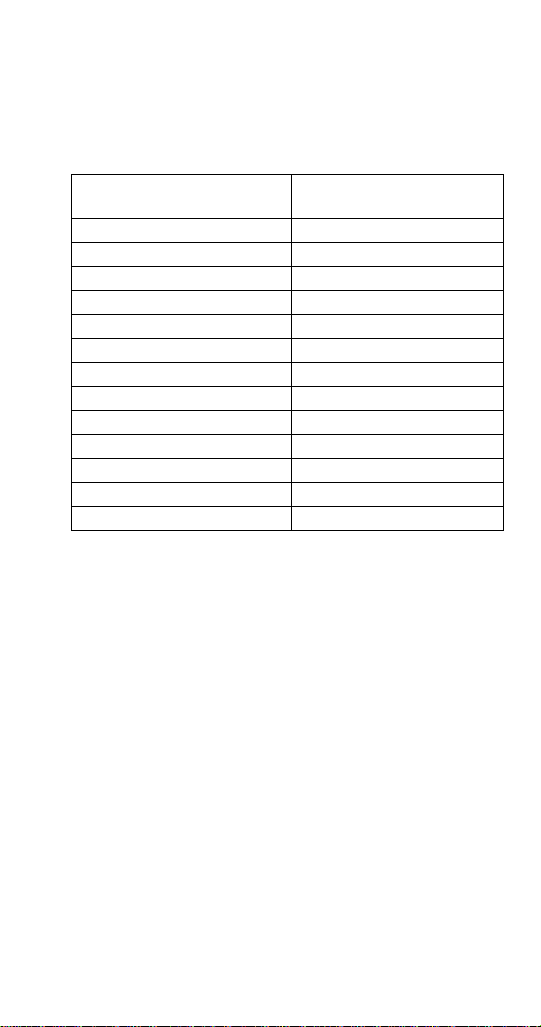
General Information
Model Numbers. . . . . . . . . . . . . . . . . . . . . . . . . . . . 1
Installation
Location of Ice Machine. . . . . . . . . . . . . . . . . . . . . 3
Water Service/Drains . . . . . . . . . . . . . . . . . . . . . . 4
Electrical Requirements . . . . . . . . . . . . . . . . . . . . 5
Electrical Specifications . . . . . . . . . . . . . . . . . . . . 6
Power Consumption - kwh per 24 hours . . . . . . . 8
Power Consumption - kwh per 24 hours . . . . . . . 9
Ice Machine Heat of Rejection. . . . . . . . . . . . . . 10
Component Identification
Component Removal . . . . . . . . . . . . . . . . . . . . . 13
Spray Bar . . . . . . . . . . . . . . . . . . . . . . . . . . . . . . 17
Maintenance
Cleaning & Sanitizing Procedure . . . . . . . . . . . . 20
Operation
Sequence Of Operation . . . . . . . . . . . . . . . . . . . . 25
Ice Cube Thickness Check. . . . . . . . . . . . . . . . . 28
Cube Shape . . . . . . . . . . . . . . . . . . . . . . . . . . . . 29
Page 8

Troubleshooting
All Models . . . . . . . . . . . . . . . . . . . . . . . . . . . . . . . .31
Ice Machine Will Not Run . . . . . . . . . . . . . . . . . .31
Compressor Won’t Run. . . . . . . . . . . . . . . . . . . .32
Compressor Electrical Diagnostics . . . . . . . . . . . 33
Diagnosing Start Components. . . . . . . . . . . . . . .35
No Timer Models . . . . . . . . . . . . . . . . . . . . . . . . . .36
Water Pump Won’t Run. . . . . . . . . . . . . . . . . . . .36
Hot Gas Valve Won’t Energize . . . . . . . . . . . . . .37
Water Inlet Valve Won’t Energize . . . . . . . . . . . .38
Ice Machine Prematurely Harvests . . . . . . . . . . .39
Ice Machine Will Not Harvest . . . . . . . . . . . . . . .40
Mechanical Timer Models . . . . . . . . . . . . . . . . . . .41
Hot Gas Valve Won’t Energize . . . . . . . . . . . . . .42
Water Inlet Valve Won’t Energize . . . . . . . . . . . .43
Ice Machine Prematurely Harvests . . . . . . . . . . .44
Ice Machine Will Not Harvest . . . . . . . . . . . . . . .45
SCR Timer Models . . . . . . . . . . . . . . . . . . . . . . . . .46
Water Pump Won’t Run. . . . . . . . . . . . . . . . . . . .46
Hot Gas Valve Won’t Energize . . . . . . . . . . . . . .47
Water Inlet Valve Won’t Energize . . . . . . . . . . . .48
Ice Machine Prematurely Harvests . . . . . . . . . . .49
Ice Machine Will Not Harvest . . . . . . . . . . . . . . .50
Water System Checklist. . . . . . . . . . . . . . . . . . . . .51
Ice Production Check. . . . . . . . . . . . . . . . . . . . . . .52
Analyzing Discharge Pressure . . . . . . . . . . . . . . .53
Discharge Pressure High Checklist. . . . . . . . . . .54
Freeze Cycle Discharge Pressure Low Checklist 55
Analyzing Suction Pressure . . . . . . . . . . . . . . . . .56
Suction Pressure High Checklist. . . . . . . . . . . . .5 8
Suction Pressure Low Checklist . . . . . . . . . . . . .59
Discharge Line Temperature Analysis. . . . . . . . . 60
Page 9

Component Check Procedures
On/Off/Wash-Fill Toggle Switch . . . . . . . . . . . . . 63
Bin Thermostat. . . . . . . . . . . . . . . . . . . . . . . . . . 64
Evaporator Thermostat. . . . . . . . . . . . . . . . . . . . 65
Mechanical Timer. . . . . . . . . . . . . . . . . . . . . . . . 67
Low Ambient Adjustment For Mechanical Timer 69
S.C.R. Timer. . . . . . . . . . . . . . . . . . . . . . . . . . . . 70
Low Ambient Adjustment For SCR Timer . . . . . 71
High Pressure Cutout (HPCO) Control. . . . . . . . 72
Hot Gas Valve . . . . . . . . . . . . . . . . . . . . . . . . . . 73
Refrigerant. . . . . . . . . . . . . . . . . . . . . . . . . . . . . . . 77
Recover/Evacuation/Charging . . . . . . . . . . . . . . 77
System Contamination Cleanup. . . . . . . . . . . . . 80
Mild System Contamination Cleanup. . . . . . . . . 82
Severe System Contamination Cleanup Procedure
. . . . . . . . . . . . . . . . . . . . . . . . . . . . . . . . . . . . . . 83
Filter-Driers. . . . . . . . . . . . . . . . . . . . . . . . . . . . . 85
Total System Refrigeration Charge . . . . . . . . . . 86
Page 10

Cycle Times/24 Hour Ice Production and
Refrigerant Pressure Charts
EC18 Self-Contained Air-Cooled — Standard Cube
. . . . . . . . . . . . . . . . . . . . . . . . . . . . . . . . . . . . . .90
EC20 (With Timer) Self-Contained Air-Cooled —
Standard Cube . . . . . . . . . . . . . . . . . . . . . . . . .93
EC20 (With Timer) Self-Contained Air-Cooled —
Large Cube . . . . . . . . . . . . . . . . . . . . . . . . . . . .96
EC20 (Without TImer) Self-Contained Air-Cooled —
Standard Cube . . . . . . . . . . . . . . . . . . . . . . . . .99
EC30 Self-Contained Air-Cooled — Standard Cube
. . . . . . . . . . . . . . . . . . . . . . . . . . . . . . . . . . . . .102
EC30 Self-Contained Air-Cooled — Large Cube
. . . . . . . . . . . . . . . . . . . . . . . . . . . . . . . . . . . . .105
EC30 (Serial Break not available) Self-Contained
Air-Cooled — Standard Cube . . . . . . . . . . . . .108
EC30 (Serial Break not available) Self-Contained
Air-Cooled — Large Cube. . . . . . . . . . . . . . . .111
EC40 Self-Contained Air-Cooled — Standard Cube
. . . . . . . . . . . . . . . . . . . . . . . . . . . . . . . . . . . . .114
EC40 Self-Contained Air-Cooled — Large Cube
. . . . . . . . . . . . . . . . . . . . . . . . . . . . . . . . . . . . .117
EC40 Self-Contained Water-Cooled — Standard
Cube . . . . . . . . . . . . . . . . . . . . . . . . . . . . . . . .120
EC40 Self-Contained Water-Cooled — Large Cube
. . . . . . . . . . . . . . . . . . . . . . . . . . . . . . . . . . . . .123
EC50 Self-Contained Air-Cooled — Standard Cube
. . . . . . . . . . . . . . . . . . . . . . . . . . . . . . . . . . . . .126
EC50 Self-Contained Air-Cooled — Large Cube
. . . . . . . . . . . . . . . . . . . . . . . . . . . . . . . . . . . . .129
EC50 Self-Contained Water-Cooled — Standard
Cube . . . . . . . . . . . . . . . . . . . . . . . . . . . . . . . .132
EC50 Self-Contained Water-Cooled — Large Cube
. . . . . . . . . . . . . . . . . . . . . . . . . . . . . . . . . . . . .135
Page 11

EC65 Self-Contained Air-Cooled — Standard Cube
. . . . . . . . . . . . . . . . . . . . . . . . . . . . . . . . . . . . . 138
EC65 Self-Contained Air-Cooled — Large Cube
. . . . . . . . . . . . . . . . . . . . . . . . . . . . . . . . . . . . . 141
EC65 Self-Contained Water-Cooled — Standard
Cube . . . . . . . . . . . . . . . . . . . . . . . . . . . . . . . 144
EC65 Self-Contained Water-Cooled — Large Cube
. . . . . . . . . . . . . . . . . . . . . . . . . . . . . . . . . . . . . 147
EC80 Self-Contained Air-Cooled — Standard Cube
. . . . . . . . . . . . . . . . . . . . . . . . . . . . . . . . . . . . . 150
EC80 Self-Contained Air-Cooled — Large Cube
. . . . . . . . . . . . . . . . . . . . . . . . . . . . . . . . . . . . . 153
EC80 Self-Contained Water-Cooled — Standard
Cube . . . . . . . . . . . . . . . . . . . . . . . . . . . . . . . 156
EC80 Self-Contained Water-Cooled — Large Cube
. . . . . . . . . . . . . . . . . . . . . . . . . . . . . . . . . . . . . 159
Diagrams
Wiring Diagram . . . . . . . . . . . . . . . . . . . . . . . . . . 163
Mechanical Timer Models . . . . . . . . . . . . . . . . 163
SCR Models. . . . . . . . . . . . . . . . . . . . . . . . . . . 164
No Timer Models . . . . . . . . . . . . . . . . . . . . . . . 165
Tubing Schematics. . . . . . . . . . . . . . . . . . . . . . . 166
EC18/EC20/EC30/EC40 Tubing Schematic. . . 166
EC50/EC65/EC80 Tubing Schematic. . . . . . . . 167
Page 12

This Page Intentionally Left Blank
Page 13
General Information
Model Numbers
This manual covers the following models:
Self-Contained
Air-Cooled
ECS018A --ECS020A ECS020W
ECG020A ECG020W
ECS030A ECS030W
ECG030A ECG030W
ECS040A ECS040W
ECG040A ECG040W
ECS050A ECS050W
ECG050A ECG050W
ECS065A ECS065W
ECG065A ECG065W
ECS080A ECS080W
ECG080A ECG080W
Water-Cooled
–1–
Page 14

This Page Intentionally Left Blank
–2–
Page 15

Installation
Location of Ice Machine
The location selected for the ice machine must meet
the following criteria. If any of these criteria are not
met, select another location.
The location must be indoors.
The location must be free of airborne and other
contaminants.
The air temperature must be at least 10ºC but must
not exceed 43.4ºC.
The location must not be near heat-generating
equipment or in direct sunlight.
The location must be capable of supporting the
weight of the ice machine and a full bin of ice.
The location must allow enough clearance for water,
drain, and electrical connections in the rear of the
ice machine.
The location must not obstruct airflow through or
around the ice machine (condenser airflow is in and
out the front). Refer to the chart below for clearance
requirements.
Self-Contained
Air-Cooled
Top/Sides 203 mm (8")* 127 mm (5")*
Back 127 mm (5")* 127 mm (5")*
*NOTE: The ice machine may be built into a cabinet.
There is no minimum clearance requirement for the
top or left and right sides of the ice machine. The listed
values are recommended for efficient operation and
servicing only.
Self-Contained
Water-Cooled
Part Number 80-1479-3 10/10 3
Page 16

WATER SERVICE/DRAINS
!
Caution
Water Supply
Local water conditions may require treatment of the
water to inhibit scale formation, filter sediment, and
remove chlorine odor and taste.
Water Inlet Lines
Do not connect the ice machine to a hot water
supply. Be sure all hot water restrictors installed for
other equipment are working. (Check valves on sink
faucets, dishwashers, etc.)
If water pressure exceeds the maximum
recommended pressure, 5 bar (500 kPA), install a
water pressure regulator.
Install a water shut-off valve.
Drain Connections
Drain lines must have a 2.5 cm per meter drop, and
must not create traps.
The floor drain must be large enough to
accommodate drainage from all drains.
The ice machine must be protected if it will be
subjected to temperatures below 0°C. Failure
caused by exposure to freezing temperatures is not
covered by the warranty.
4 Part Number 80-1479-3 10/10
Page 17

ELECTRICAL REQUIREMENTS
Voltage
The maximum allowable voltage variation is ±6% of
the rated voltage on the ice machine model/serial
number plate at start-up (when the electrical load is
highest).
All ice machines are factory pre-wired with a power
cord only, no plug is supplied.
Fuse/Circuit Breaker
A separate fuse/circuit breaker must be provided for
each ice machine. An electrical disconnect switch
must be provided if the ice machine is hard wired
(wired without a plug).
Total Circuit Ampacity
The total circuit ampacity is used to help select the
wire size of the electrical supply.
The wire size (or gauge) is also dependent upon
location, materials used, length of run, etc., so a
qualified electrician must make the determination.
Part Number 80-1479-3 10/10 5
Page 18

6 Part Number 80-1479-3 10/10
ELECTRICAL SPECIFICATIONS
Ice
Machine
EC18
EC20
EC30
EC40
Voltage
Phase
Cycle
115/60/1 NA NA
230/50/1 10 amp 2.2 NA NA
230/60/1 10 amp 2.2 NA NA
115/60/1 115/60/1 NA
230/50/1 10 amp 2.5 230/50/1 10 amp 2.3
230/60/1 10 amp 2.5 230/60/1 10 amp 2.3
115/60/1 115/60/1
230/50/1 10 amp 3.4 230/50/1 10 amp 3.2
230/60/1 10 amp 3.4 230/60/1 10 amp 3.2
230/50/1 10 amp 3.4 230/50/1 10 amp 3.1
230/60/1 10 amp 3.4 230/60/1 10 amp 3.1
Air Water
Max. Fuse/
Circuit
Breaker
Total
Amps
Voltage
Phase
Cycle
Max. Fuse/
Circuit
Breaker
Total
Amps
Page 19

Part Number 80-1479-3 10/10 7
EC50
EC65
EC80
115/60/1 115/60/1
230/50/1 10 amp 4.0 230/50/1 10 amp 3.7
230/60/1 10 amp 4.0 230/60/1 10 amp 3.7
115/60/1 115/60/1
230/50/1 10 amp 4.2 230/50/1 10 amp 3.8
230/60/1 10 amp 4.2 230/60/1 10 amp 3.8
115/60/1 115/60/1
230/50/1 10 amp 4.4 230/50/1 10 amp 4.0
230/60/1 10 amp 4.4 230/60/1 10 amp 4.0
Page 20

POWER CONSUMPTION - KWH PER 24 HOURS
Model
ECS18A 6.4 6.5 6.8
ECS20A 7.1 7.4 7.8
ECG20A 9.2 9.8 10.5
ECS20W 6.2 6.3 6.4
ECG20W 6.0 6.0 6.2
ECS30A 10.0 10.4 11.1
ECG30A 7.1 7.4 7.8
ECS30W 8.9 8.9 9.2
ECG30W 8.9 8.9 8.9
ECS40A 11.1 11.6 12.3
ECG40A 11.0 11.5 12.2
ECS40W 9.5 9.4 9.2
ECG40W 9.2 9.4 9.2
Air Temp/Water Temp
25/15 32/21 43/32
8 Part Number 80-1479-3 10/10
Page 21

POWER CONSUMPTION - KWH PER 24 HOURS
Model
ECS50A 12.9 13.3 14.4
ECG50A 12.6 13.0 14.0
ECS50W 11.1 11.2 11.5
ECG50W 11.0 10.9 11.4
ECS65A 12.6 13.1 14.1
ECG65A 12.9 13.2 14.1
ECS65W 11.2 11.3 11.7
ECG65W 11.0 10.9 11.4
ECS80A 15.4 16.3 17.4
ECG80A 15.1 15.8 16.9
ECS80W 13.6 13.8 13.9
ECG80W 13.2 13.4 13.7
Air Temp/Water Temp
25/15 32/21 43/32
Part Number 80-1479-3 10/10 9
Page 22

ICE MACHINE HEAT OF REJECTION
Series Ice
Machine
Air Conditioning Peak
Heat of Rejection
EC18 1,150 2,300
EC20 1,400 2,600
EC30 1,900 3,300
EC40 2,100 4,100
EC50 2,600 5,000
EC65 2,900 5,000
EC80 4,300 7,400
BTU/Hour
Because the heat of rejection varies during the ice
making cycle, the figure shown is an average.
10 Part Number 80-1479-3 10/10
Page 23
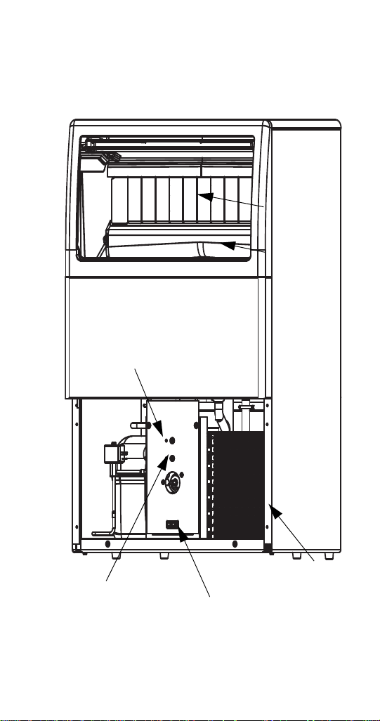
Component Identification
Water
Curtains
Bin
Thermostat
On/Off/Wash-Fill
Toggle Switch
Air Cooled
Condenser
Water
Trough
Evaporator
Thermostat
Part Number 80-1479-3 10/10 11
Page 24
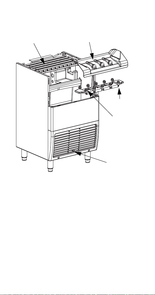
Evaporator
Ice Chute
Spray Bar
Spray
Nozzles
Toggle
Switch
12 Part Number 80-1479-3 10/10
Page 25
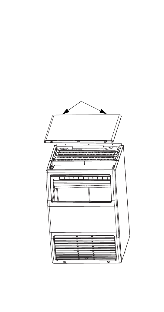
COMPONENT REMOVAL
Remove 2 Screws and
Slide Cover Back
Top Cover
For easiest access to the evaporator compartment, the
top cover can be removed.
1. Remove two screws on the rear of the ice
machine.
2. Slide top cover back to disengage the three pins
from the front panel
Part Number 80-1479-3 10/10 13
Page 26
Bin Door
Align Door Pins With
Track Slots, Then Lift
Door Out Of Track
Allows access to the storage bin.
1. Remove top cover.
2. Slide door up until rear pins align with slot in door
tracks.
3. Lift rear door pins out and slide door up until front
door pins align with slot.
4. Lift door out of door track
14 Part Number 80-1479-3 10/10
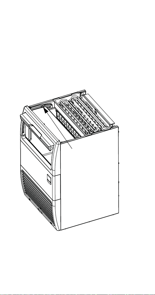
Page 27
Water Curtain
Water Curtain
The water curtain is designed to keep the spraying
water from escaping the evaporator compartment.
Removal of the bin door is not required, but enhances
access.
1. Grasp one end of the ice curtain and lift up.
2. Pivot water curtain and disengage remaining end.
3. To re-install into ice machine, grasp one end of
the water curtain, install one end, pivot the
opposite end and pull down into position. Make
sure tabs are secure in grooves.
Part Number 80-1479-3 10/10 15
Page 28
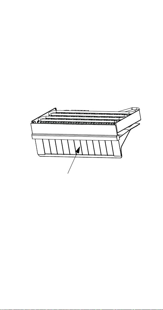
Ice Chute
Ice Chute
The ice chute is positioned over the spray nozzles and
allows the ice to easily fall into the bin. It must be firmly
positioned over the Spray Bar Assembly, with the front
edge inside the water trough or the spray nozzles will
not be aligned with the spray holes, and spray water
will fall into bin.
1. Grab protruding spray holes on one end and lift
up.
2. Pivot ice chute and remove.
3. To re-install ice chute, grasp protruding spray
holes and position over Spray Bar Assembly.
Make sure rear supports are over Spray Bar
Assembly, and front edge is inside of water trough
16 Part Number 80-1479-3 10/10
Page 29
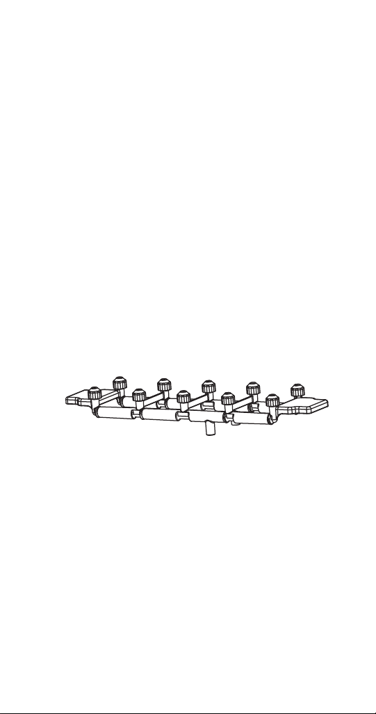
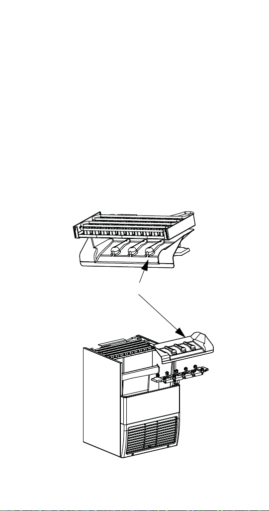
SPRAY BAR
The spray bar supplies water to the individual icemaking cups. Water from the Water Pump sprays
through the nozzles, located on the upper portion of
the tubes.
1. Grasp one end of the spray bar, lift up and remove
from seat formed in water trough.
2. Remove both plastic clips on water inlet tubing by
grasping both ears on clip and separating.
3. Apply food grade lubricate to ease re-assembly of
spray bar components when necessary.
4. To re-install spray bar, position water inlet tubing
on inlet ports, and squeeze clips until tight.
5. Reposition assembly on water trough seat.
NOTE: Nozzles and inserts can be removed for
cleaning by unscrewing nozzles. Inserts are located
inside the spray bar ports. The spray bar also
disassembles for easy cleaning
Part Number 80-1479-3 10/10 17
Page 30
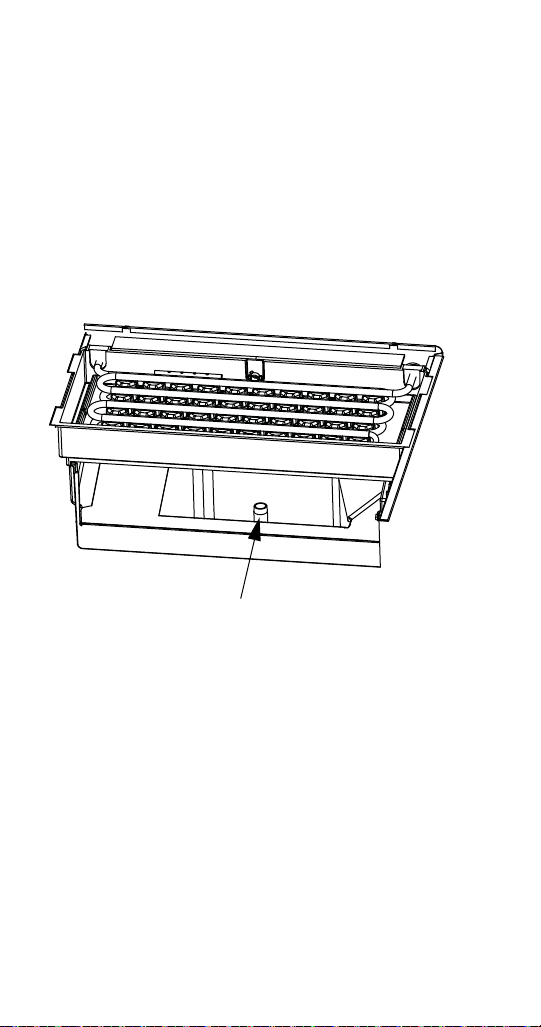
Sump Drain Overflow Tube
Overflow Tube
The sump drain overflow tube is located in the
evaporator water sump.
1. Remove shutters and ice chute.
2. Lift spray bar or disconnect and remove for
easiest access.
3. Pull up on over flow tube to remove.
To replace plug, insert in hole, and push with force to
make a tight seal
18 Part Number 80-1479-3 10/10
Page 31

Maintenance
!
Caution
!
Warning
INTERIOR CLEANING AND SANITIZING
GENERAL
Clean and sanitize the ice machine every six months
for efficient operation. If the ice machine requires more
frequent cleaning and sanitizing, consult a qualified
service company to test the water quality and
recommend appropriate water treatment.
An extremely dirty ice machine must be taken apart for
cleaning and sanitizing.
Use only approved Ice Machine Cleaner and
Sanitizer. Read and understand all labels printed on
bottles before use. Do not mix Ice Machine Cleaner
and Sanitizer solutions together
Wear rubber gloves and safety goggles (and/or face
shield) when handling Ice Machine Cleaner or
Sanitizer.
Part Number 80-1479-3 10/10 19
Page 32

CLEANING & SANITIZING PROCEDURE
!
Caution
Ice machine cleaner is used to remove lime scale or
other mineral deposits. Sanitizer is used to remove
algae or slime.
Step 1 Mix 4 liters of water with 500 ml of cleaner in a
plastic or stainless container.
Cleaner Water
500 ml (16 oz) 4 l (1 gal)
Step 2 Set the togg le switch to the OFF posi tion at the
end of a Harvest Cycle, after ice releases from the
evaporator. Or, set the switch to the OFF position and
allow the ice to melt off the evaporator.
Step 3 Remove all ice from the bin.
Never use anything to force ice from the evaporator.
Damage may result.
Step 4 Remove all parts as described in the
Component Identification & Removal section.
Step 5 Take all components to sink and with 2 liters
Cleaner/Water mixture clean all components with a
soft nylon brush. Disassemble spray bar, remove
nozzles and inserts and soak for 5 minutes. For
heavily scaled parts, soak in solution for 15 – 20
minutes. Rinse all components with clean water.
20 Part Number 80-1479-3 10/10
Page 33

Step 6 While components are soaking; use nylon
brush to scrub inside of ice bin. Scrub inside of door,
door track, bin, sump trough, and evaporator
moldings. With clean water, rinse all of these areas
thoroughly.
Step 7 Replace sump overflow tube and pour
remaining 2 liters of mixture into the water sump.
Replace all parts.
Step 8 Disconnect the incoming ice-making water line.
Step 9 To start a cleaning cycle, set the toggle switch
to the WASH/FILL position.
Step 10 After 10 minutes, set the toggle switch to the
OFF position. Remove water curtain, ice chute and
over flow tube from the water sump. Allow all water to
drain from the sump. Replace drain plug and fill sump
with 2 liters of water. Set toggle switch to WASH
/FILL
and circulate for 10 minutes.
Step 11 After 10 minutes, set toggle switch to off
position. Remove water curtain, ice chute, water sump
over flow tube. Drain water from sump and replace
tube.
Step 12 Mix 60 ml of sanitizer with 12 l of water in a
plastic or stainless steel container.
Sanitizer Water
60 ml (2 oz) 12 l (3 gal)
Part Number 80-1479-3 10/10 21
Page 34

Step 13 Remove Water Curtain and Ice Chute.
Step 14 Take all components to sink and with 10 liters
Sanitizer/Water mixture sanitize all components with a
soft nylon brush or cloth. Do not rinse components.
Step 15 Use brush or cloth to sanitize the inside of ice
bin. Scrub inside of door, door track, bin, water sump,
water distribution assembly and evaporator moldings.
Do not rinse.
Step 16 Replace sump drain over flow tube, and
transfer remaining 2 liters of solution to th e sump
trough. Replace all components.
Step 17 To start a sanitizing cycle, set the toggle
switch to the WASH
/FILL position.
Step 18 After 10 minutes, set the toggle switch to the
OFF position. Remove water curtain and ice chute
Remove over flow tube from water sump and allow all
water to drain from sump. Replace drain plug and fill
sump with 2 liters of water. Set toggle switch to WASH
FILL and circulate for 10 minutes.
Step 19 After 10 minutes, set toggle switch to off
position. Remove water curtain, ice chute, water sump
over flow tube. Drain water from sump and replace
tube.
Step 20 Replace all parts. Connect the incoming icemaking water line
.
Step 21 Place toggl e sw i tch to the WASH/FILL for 90
seconds and then to ice position,ice machine will go
into ice making cycle.
/
22 Part Number 80-1479-3 10/10
Page 35

EXTERIOR CLEANING
!
Caution
Clean the area around the ice machine as often as
necessary to maintain cleanliness and efficient
operation.
Sponge any dust and dirt off the outside of the ice
machine with mild soap and water. Wipe dry with a
clean, soft cloth.
A commercial grade stainless steel cleaner and polish
may be used.
REMOVAL FROM SERVICE/WINTERIZATION
GENERAL
Special precautions must be taken if the ice machine is
to be removed from service for an extended period of
time or exposed to ambient temperatures of 0C
(32F) or below.
If water is allowed to remain in the ice machine in
freezing temperatures, severe damage to some
components could result. Damage of this nature is
not covered by the warranty.
Follow the applicable procedure below.
AIR-COOLED ICE MACHINES
1. Disconnect the electric power at the circuit
breaker or the electric service switch.
2. Turn off the water supply.
3. Drain the water from the water sump and water
pump by disconnecting the water pump tubing.
4. Disconnect and drain the incoming ice-making
water line and disconnect the tubing from the
water inlet valve outlet and allow water to drain.
5. Blow compressed air in the drain opening and
water valve outlet hose, then reattach.
6. Make sure water is not trapped in any of the water
or drain lines.
Part Number 80-1479-3 10/10 23
Page 36

WATER-COOLED ICE MACHINES
1. Perform steps 1-6 under “Air-Cooled Ice
Machines.”
2. Disconnect the incoming water and drain lines
from the water-cooled condenser.
3. Insert a large screwdriver between the bottom
spring coils of the water regulating valve. Pry
upward to open the valve.
4. Hold the valve open and blow compressed air
through the condenser until water no longer exits.
24 Part Number 80-1479-3 10/10
Page 37

Operation
Sequence Of Operation
Initial Start-Up
PRIMING WATER SYSTEM
Models built July 2010 or later:
Place the toggle switch in the wash/fill position, the
water fill valve and water pump energize. Wait 90
seconds for the water system to fill, then place the
toggle switch in the ice position.
Models built before July 2010:
The water inlet valve energizes in the harvest
sequence, therefore priming the system with water will
allow the system to start up with a full reservoir of
water. To prime system, remove water curtain, and
add 2 liters of water into the water trough.
Continued Next Page
Part Number 80-1479-3 10/1025
Page 38

1. Freeze Cycle
Turn the toggle switch to ON. The compressor, and
water pump will energize, starting the freeze cycle.
The pump sprays water into the inverted cups. The
water freezes layer by layer, until an ice cube forms in
each cup.
At the same time the compressor starts, the
condenser fan motor (air-cooled models) is supplied
with power throughout the freeze and harvest cycles.
The freeze cycle continues and the evaporator
thermostat reaches the adjusted se t po i nt .
No Timer
A harvest cycle starts
Mechanical Timer
The thermostat energizes the timer motor and the cam
starts to turn. When the cam cycles through the preset
freeze time the relays change position and the harvest
cycle is initiated.
SCR Timer
The thermostat energizes the time delay relay. When
the timer reaches setpoint (11.5 minute factory setting)
the harvest cycle is initiated.
26 Part Number 80-1479-3 10/10
Page 39

2. Harvest Cycle
The compressor continues to operate and the water
pump is de-energized. The hot gas valve energizes,
allowing hot gas to enter and warm the evaporator.
The water valve is also energized, aiding with harvest,
as well as filling up the sump with fresh water for a
new freeze cycle.
The ice falls from the cups and is directed into the bin
by the ice chute. The harvest cycle continues until:
No Timers
The evaporator thermostat changes position.
Mechanical Timer
The preset harvest time expires.
The hot gas valve and water valve de-energize. If ice
cubes are not contacting the bin thermostat, a new
freeze cycle is initiated as the water pump energizes
and sprays water into the cups.
SCR Timer
The timer reaches the factory setting of 3 minutes.
3. Automatic Shut-Off
When the storage bin is full, the ice will come in
contact with the bin thermostat which is located inside
the bin. The machine will stop after approximately one
minute of continuous ice contact with the bin
thermostat probe.
The ice machine remains off until enough ice has been
removed from the storage bin to allow the ice to fall
clear of the bin thermostat probe. As the ice clears the
probe, the bin thermostat warms up and the machine
starts another freeze cycle.
Part Number 80-1479-3 10/1027
Page 40

ICE CUBE THICKNESS CHECK
The ice cube thickness is factory-set to maintain the
ice cube thickness at the proper size and weight.
Allow the ice machine to operate for three complete
cycles. The cubes should have a small dimple in the
center.
Cycle times vary, according to surrounding air and
water inlet temperatures.
If cubes are not full (large dimple), turn evaporator
thermostat one increment towards the right to increase
cube size. Allow ice machine to complete three cycles,
then check cubes.
If cubes are too full, (no dimple), turn evaporator
thermostat one increment towards the left to decrease
cube size. Allow ice machine to operate three
complete cycles, then check cubes.
Ice Cube Adjustment
28 Part Number 80-1479-3 10/10
Page 41

CUBE SHAPE
The standard cube has an average weight of 19
grams, and the large cube has an average weight of
32 grams.
Notice the normal dimple in the center of the cube.
Part Number 80-1479-3 10/1029
Page 42

30 Part Number 80-1479-3 10/10
This Page Intentionally Left Blan k
Page 43

Troubleshooting
4
All Models
ICE MACHINE WILL NOT RUN
Nothing on the ice machine will operate (compressor,
water pump, condenser fan motor). If any component
runs this procedure can be skipped, move on to the
next diagnostics (water pump won’t run, compressor
won’t run, etc).
1. Place the toggle switch in the clean position. If the
water pump runs begin with toggle switch
diagnostics. If water pump does not run place
toggle switch in ice position.
2. Verify correct voltage is present and matche s
nameplate voltage.
3. High pressure switch must be closed on water
cooled ice machines — move on to #4 if air cooled
ice machine (If you have voltage at L1 and no
voltage at #15 on the Bin Thermostat, which is easy
to access, the HPCO is open).
4. Bin thermostat must be closed before any
components can be energized. Check for voltage
at wires #15 and #64.
Part Number 80-1479-3 10/10 31
Page 44

COMPRESSOR WON’T RUN
3
2
1
If the water pump is running and the compressor is
not, it may be tripping on overload or tripping the
breaker/fuse. Check for grounded winding if breaker
keeps tripping.
1. Toggle switch terminals 5 & 4 closed?
(wires #49 & #13)
2. Start capacitor and relay function?
3. Compressor windings closed?
4. Refer to compressor diagnostics.
32 Part Number 80-1479-3 10/10
Page 45

COMPRESSOR ELECTRICAL DIAGNOSTICS
The compressor does not start or will trip repeatedly
on overload.
Check Resistan c e (OH M) Values
NOTE: Compressor windings can have very low ohm
values. Use a properly calibrated meter.
Perform the resistance test after the compressor
cools. The compressor dome should be cool enough
to touch (below 49°C) to assure that the overload is
closed and the resistance readings will be accurate.
Single Phase Compressors
1. Disconnect power from the condensing unit and
remove the wires from the compressor terminals.
2. The resistance values between C and S and
between C and R, when added together should
equal the resistance value between S and R.
3. If the overload is open, there will be a resistance
reading between S and R, and open readings
between C and S and between C and R. Allow the
compressor to cool, then check the readings again.
Check Motor Windings to Ground
Check continuity between all three terminals and the
compressor shell or copper refrigeration line. Scrape
metal surface to get good contact. If continuity is
present, the compressor windings are grounded and
the compressor should be replaced.
To determine if the Compressor is seized check the
amp draw while the compressor is trying to start.
Part Number 80-1479-3 10/10 33
Page 46

Compressor Drawing High Amps
The continuous amperage draw on start-up should not
be near the maximum fuse size indicated on the serial
tag.
The wiring must be correctly sized to minimize voltage
drop at compressor start-up. The voltage when the
compressor is trying to start must be within (6% of the
nameplate voltage).
Compressor Drawing Locked Rotor
The three likely causes of this are:
Low voltage supply (check voltage while
compressor is trying to start)
Defective starting component
Mechanically seized compressor
To determine which you have:
Install high and low side gauges.
Try to start the compressor.
Watch the pressure s clo se l y.
If the pressures do not move, the compressor is
seized. Replace the compressor.
If the pressures move, the compressor is turning
slowly and is not seized. Check the capacitors and
relay.
34 Part Number 80-1479-3 10/10
Page 47

DIAGNOSING START COMPONENTS
If the compressor attempts to start, or hums and trips
the overload protector, check the start components
before replacing the compressor.
Capacitor
Visual evidence of capacitor failure can include a
bulged terminal end or a ruptured membrane. Do not
assume a capacitor is good if no visual evidence is
present. A good test is to install a known good
substitute capacitor. Use a capacitor tester when
checking a suspect capacitor. Clip the bleed resistor
off the capacitor terminals before testing.
Current Relay
The relay has a set of contacts that energize and deenergize the compressor start winding. The contacts
on the relay are normally open (start winding deenergized). When power is applied the run winding will
be at LRA. The relay coil will become an
electromagnet and close the contacts (start winding
energized). As the compressor motor RPM increases,
the run winding current draw and relay coil magnetism
decrease allowing the contacts to open. Replace a
suspect relay with a known good relay, or use a
momentary switch and start capacitor to mimic relay
operation.
Part Number 80-1479-3 10/10 35
Page 48

No Timer Models
WATER
PUMP
EVAP THERMOSTAT
TOGGLE SWITCH
31264
5
(8)
(5)
C
H
L
(3)
(49)
(65)
(64)
1
2
3
WATER PUMP WON’T RUN
No Timer Models
1. Toggle switch terminals 2 & 1 closed?
(wires #64 & #3)
2. Evaporator thermostat C & L contacts closed?
(wires #3 & #5)
3. Water pump winding closed?
36 Part Number 80-1479-3 10/10
Page 49

HOT GAS VALVE WON’T ENERGIZE
(22)
HOT GAS
SOLENOID
WATER INLET
SOLENOID
EVAP THERMOSTAT
(21)
(7)
(10)
(6)
C
H
L
(3)
1
No Timer Models
1. V erify the evaporator temperature is below setpoint,
then refer to evaporator thermostat check
procedure to verify the evaporator thermostat is
operating correctly.
2. Line voltage at hot gas valve? (Wires 6& 7)
Yes - Replace hot gas valve coil.
No - Refer to evaporator thermostat diagnostics.
Part Number 80-1479-3 10/10 37
Page 50

WATER INLET VALVE W ON’T ENERGIZE
(22)
HOT GAS
SOLENOID
WATER INLET
SOLENOID
EVAP THERMOSTAT
(21)
(7)
(10)
(6)
C
H
L
(3)
1
No Timer
1. Line voltage at water inlet valve? (Wires 21 & 22)
Yes - Replace water inlet valve coil.
No - Refer to evaporator thermostat diagnostics.
38 Part Number 80-1479-3 10/10
Page 51

ICE MACHINE PREMATURELY HARVESTS
(22)
HOT GAS
SOLENOID
WATER INLET
SOLENOID
EVAP THERMOSTAT
(21)
(7)
(10)
(6)
C
H
L
(3)
1
2
No Timer
1. Line voltage at hot gas valve?
Yes - Replace hot gas valve.
No - Refer to evaporator thermostat diagnostics.
Part Number 80-1479-3 10/10 39
Page 52

ICE MACHINE WILL NOT HARVEST
(22)
HOT GAS
SOLENOID
WATER INLET
SOLENOID
EVAP THERMOSTAT
(21)
(7)
(10)
(6)
C
H
L
(3)
1, 2 & 3
4
No Timer
1. Evaporator temperature below setpoint?
2. Evaporator thermostat cap tube inserted correctly?
(Flush with end of bulb well)
3. Evaporator thermostat closed?
(wires #4 & timer motor)
4. Line voltage at hot gas valve and water inlet
Solenoid?
40 Part Number 80-1479-3 10/10
Page 53

Mechanical Timer Models
3
2
1
WATER PUMP WON’T RUN
Mechanical Timer
1. Toggle switch terminals 2 & 1 closed?
(wires #64 & #3)
2. Timer micro switch closed (relay 2)?
(wires #33 & #5)
3. Water pump winding closed?
Part Number 80-1479-3 10/10 41
Page 54

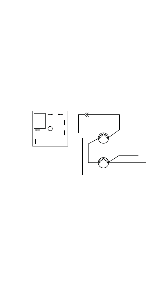
HOT GAS VALVE WON’T ENERGIZE
3
2
1
Mechanical Timer
1. Toggle switch terminals 2 & 1 closed?
(wires #64 & #3)
2. Timer micro switch closed (relay 1)?
(wires #3 & #6)
3. Hot gas valve coil winding closed?
42 Part Number 80-1479-3 10/10
Page 55

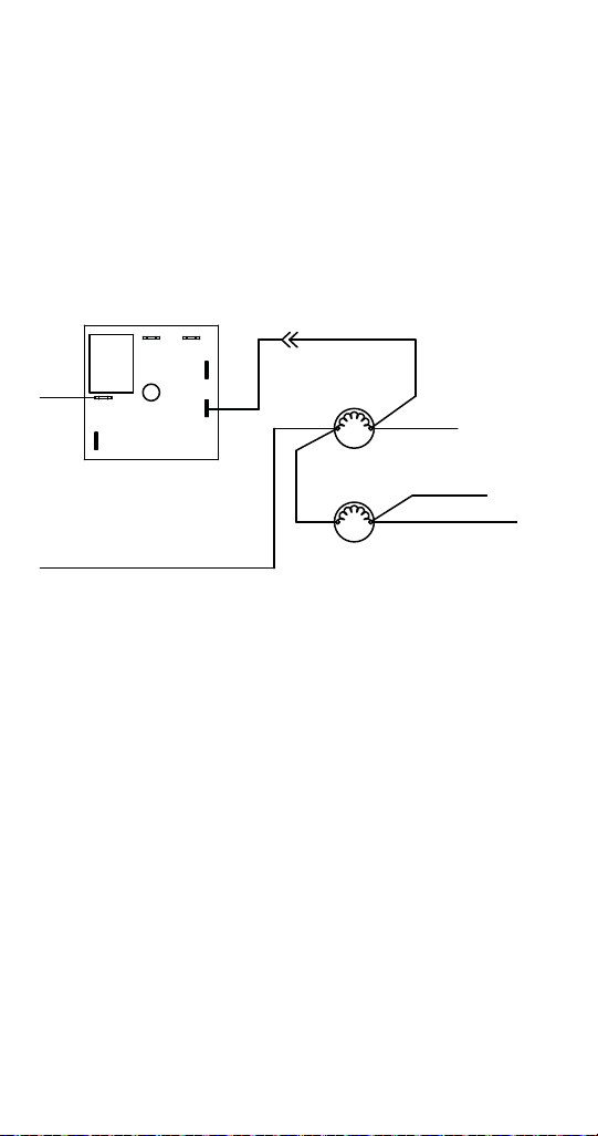
WATER INLET VALVE W ON’T ENERGIZE
3
2
4
Mechanical Timer
The hot gas valve and water inlet valve energize
together in the harvest cycle. If the hot gas valve
energizes verify #1 and then go right to #4.
1. Water supplied to the ice machine?
2. Toggle switch terminals 2 & 1 closed?
(wires #64 & #3)
3. Timer micro switch closed (relay 1)?
(wires #3 & #6)?
4. Water inlet valve coil winding closed?
Part Number 80-1479-3 10/10 43
Page 56

ICE MACHINE PREMATURELY HARVESTS
3
2
1
4
Mechanical Timer
1. Evaporator thermostat correctly set?
2. Timer micro switch relays in N.O. position?
(wires #3 & #6-16 open - wires #33 & #4-5 closed)
3. Evaporator thermostat terminals #2 & #3
(Common) open?
4. Timer motor winding closed?
5. Timer functions mechanically?
6. Timer cam changes relay micro switch position?
(relay 1 - wires #3 & #6-16 must close.
44 Part Number 80-1479-3 10/10
Page 57

ICE MACHINE WILL NOT HARVEST
3
8
5
7
4
Mechanical Timer
1. Evaporator temperature below setpoint?
2. Evaporator thermostat cap tube inserted correctly?
(Flush with end of bulb well)
3. Evaporator thermostat closed?
(wires #4 & timer motor)
4. Timer motor winding closed?
5. Timer functions mechanically?
6. Timer cam changes micro switch position?
(relay 1 - wires #3 & #6 must close)
7. Micro switch functions?
8. Line voltage at hot gas valve and water inlet
Solenoid? (wires #6 & #7 - wires #21 & #10).
Part Number 80-1479-3 10/10 45
Page 58

SCR Timer Models
NCC
NO
6
2
TIME DELAY
RELAY
1
RELAY
WATER
PUMP
TOGGLE SWITCH
3 1264
5
(8)
(5)
(33)
(3)
(49)
(65)
(64)
1
2
3
WATER PUMP WON’T RUN
SCR Timer
1. Toggle switch terminals 2 & 1 closed?
(wires #64 & #3)
2. Timer relay closed?
(wires #3 & #5 - contacts C & NC on timer)
3. Water pump winding closed?
46 Part Number 80-1479-3 10/10
Page 59

HOT GAS VALVE WON’T ENERGIZE
(22)
NCC
NO
6
2
TIME DELAY
RELAY
1
RELAY
HOT GAS
SOLENOID
WATER INLET
SOLENOID
(21)
(9)
(7)
(10)
(6)
1
SCR Timer
1. Line voltage at hot gas valve? (Wires 6& 7)
Yes - Replace hot gas valve coil.
No - Refer to SCR timer diagnostics.
Part Number 80-1479-3 10/10 47
Page 60
WATER INLET VALVE W ON’T ENERGIZE
(22)
NCC
NO
6
2
TIME DELAY
RELAY
1
RELAY
HOT GAS
SOLENOID
WATER INLET
SOLENOID
(21)
(9)
(7)
(10)
(6)
1
SCR Timer
1. Line voltage at water inlet valve? (Wires 21& 22)
Yes - Replace water inlet valve.
No - Refer to SCR timer diagnostics.
48 Part Number 80-1479-3 10/10
Page 61
ICE MACHINE PREMATURELY HARVESTS
(22)
NCC
NO
6
2
TIME DELAY
RELAY
1
RELAY
HOT GAS
SOLENOID
WATER INLET
SOLENOID
(21)
(9)
(7)
(10)
(6)
1
2
3
SCR Timer
1. Line voltage at hot gas valve?
No - Replace hot gas valve
2. Line voltage at NO and 2 terminals on SCR timer?
3. Line voltage at 6 & 2 on SCR timer?
No - Replace SCR timer.
Part Number 80-1479-3 10/10 49
Page 62

ICE MACHINE WILL NOT HARVEST
2
C
NC
NO
1
6
5
4
3
2
5
15
13
11
9
7
1
6
SCR Timer
1. Check for line voltage at terminals 1 & 2 and C & 2.
If line voltage is not present refer to toggle switch
diagnostics.
2. Check for line voltage at 2 & 6.
No line voltage
Refer to evaporator thermostat diagnostics.
Evaporator temperature must be below setpoint.
Line Voltage
Momentarily disconnect then reconnect power to #6.
3. Wait 11 minutes.
Ice machine cycles into harvest - Refer to
evaporator thermostat diagnostics.The evaporator
thermostat must open the trigger contact (#6) to
reset the freeze cycle time. If power is not broken at
# 6 the ice machine will remain in the freeze cycle
and never initiate a harvest cycle.
Ice machine remains in freeze - Replace timer.
50 Part Number 80-1479-3 10/10
Page 63

Water System Checklist
A water-related problem often causes the same
symptoms as a refrigeration system component
malfunction.
Water system problems must be identified and
eliminated prior to replacing refrigeration components.
Water area (evaporator) is dirty
Clean as needed
Water inlet pressure not between 1.4 and 5.5 bar
Install a water regulator valve or increase the water
pressure
Incoming water temperature is not between
1.7°C and 32.2°C
If too hot, check the hot water line check valves in
other store equipment
Water filtration is plugged (if used)
Install a new water filter
Hoses, fittings, etc., are leaking water
Repair/replace as needed
Water inlet valve is stuck open or closed
Clean/replace as needed
Water is spraying out of the sump trough area
Stop the water spray
Uneven water flow across the evaporator
Clean the ice machine
Part Number 80-1479-3 10/10 51
Page 64

Ice Production Check
The amount of ice a machine produces directly relates
to the operating water and air temperatures. This
means an ice machine with a 20°C outdoor ambient
temperature and 10.0°C water produces more ice than
the same model ice machine with a 32°C outdoor
ambient and 21°C water.
1. Determine the ice machine operating conditions:
Air temp entering condenser: ____°
Air temp around ice machine: ____°
Water temp entering sump trough: ____°
2. Refer to the appropriate 24-Hour Ice Production
Chart.
3. Use the operating conditions determined in Step 1
to find published 24 hr. ice production: ____
Times are in minutes.
Example: 1 min., 15 sec. converts to 1.25 min.
(15 seconds ÷ 60 seconds = .25 minutes)
Weights are in grams.
4. Perform an ice production check using the formula
below.
1. _________
Freeze Time
2. 1440
_________
Minutes in
24 Hrs.
3. _________
Weight of One
Harvest
+ _________
Harvest Time
_________
Total Cycle
Time
× _________
Cycles per Day
= _________
Total Cycle
Time
_________
Cycles per Day
= _________
Actual 24-Hour
Production
Weighing the ice is the only 100% accurate check.
Compare the results of Step 3 with Step 2. Ice
production is normal when these numbers match
closely. If they match closely, determine if:
Another ice machine is required.
Relocating the existing equipment to lower the load
conditions is required.
52 Part Number 80-1479-3 10/10
Page 65

Analyzing Discharge Pressure
1. Determine the ice machine operating conditions:
Air temp. entering condenser ______
Air temp. around ice machine ______
Water temp. entering sump trough ______
2. Refer to Cycle Times/24 Hour Ice Production/
Refrigeration Pressure Chart for ice machine being
checked.
3. Use the operating conditions determined in Step 1
to find the published normal discharge pressures.
Freeze Cycle ______
Harvest Cycle ______
Perform an actual discharge pressure check.
Freeze Cycle
PSIG
Beginning
of Cycle
Middle
of Cycle
End
of Cycle
__________ __________
__________ __________
__________ __________
Compare the actual discharge pre ssure (Step 3) with
the published discharge pressure (Step 2).
The discharge pressure is normal when the actual
pressure falls within the published pressure range for
the ice machine’s operating conditions. It is normal for
the discharge pressure to be higher at the beginning of
the freeze cycle (when load is greatest), then drop
throughout the freeze cycle.
Harvest Cycle
PSIG
Part Number 80-1479-3 10/10 53
Page 66

DISCHARGE PRESSURE HIGH CHECKLIST
Improper Installation
Refer to “Installation/Visual Inspection Checklist”
Restricted Condenser Air Flow
High inlet air temperature
Condenser discharge air re-circulation
Dirty condenser fins
Defective fan motor
Improper Refrigerant Charge
Overcharged
Non-condensable in system
Wrong type of refrigerant
Other
High side refrigerant lines/component restricted
(before mid-condenser)
54 Part Number 80-1479-3 10/10
Page 67

FREEZE CYCLE DISCHARGE PRESSURE LOW
CHECKLIST
Improper Installation
Refer to “Installation/Visual Inspection Checklist”
Improper Refrigerant Charge
Undercharged
Wrong type of refrigerant
Other
High side refrigerant lines/component restricted
(before mid-condenser)
NOTE: Do not limit your diagnosis to only the items
listed in the checklists.
Part Number 80-1479-3 10/10 55
Page 68

Analyzing Suction Pressure
The suction pressure gradually drops throughout the
freeze cycle. The actual suction pressure (and drop
rate) changes as the air and water temperature
entering the ice machine changes. These variables
also determine the freeze cycle times.
To analyze and identify the proper su ction pressure
drop throughout the freeze cycle, compare the
published suction pressure to the published freeze
cycle time.
NOTE: Analyze discharge pressure before analyzing
suction pressure. High or low discharge pressure may
be causing high or low suction pressure.
56 Part Number 80-1479-3 10/10
Page 69

Procedure
20
1.17
140
1.94
.41
Step
1. Determine the ice
machine operating
conditions.
2A. Refer to “Cycle Time” and
“Operating Pressure”
charts for ice machine
model being checked.
Using operating
conditions from Step 1,
determine published
freeze cycle time and
published freeze cycle
suction pressure.
2B. Compare the published
freeze cycle time and
published freeze cycle
suction pressure. Develop
a chart.
3. Perform an actual sucti on
pressure check at the
beginning, middle and end
of the freeze cycle. Note
the times at which the
readings are taken.
4. Compare the actual
freeze cycle suction
pressure (Step 3) to the
published freeze cycle
time and pressure
comparison (Step 2B ).
Determine if the suction
pressure is high, low or
acceptable.
Example Using ECS040A Model Ice
Air temp. entering condenser:
32°C
Water temp. entering water fill valve:
21°C
40 minutes
Published Freeze cycle time:
1.94 to.41 bar
Published Freeze cycle suction pressure:
Published Freeze Cycle Suction
In the example, the proper suction pressure
should be approximately 1.94 bar at 1 minute;
Manifold gauges were connected to the
example ice machine and suctio n pressure
readings taken as follows:
Beginning of Freeze cycle:3 bar (at 1 min.)
Middle of Freeze cycle:2 bar (at 20 min.)
End of Freeze cycle:1 bar (at 40 min.)
In this example, the suction pressure is
considered high throughout the fre eze cycle.
It should have been:
Approximately 1.94 bar
(at 1 minute) – not 3 bar
Approximately 1.17 bar
(at 20 minutes) – not 2 bar
Approximately .41 bar
(at 40 minutes) – not 1 bar
Machine
Published Freeze Cycle Time
(minutes)
Pressure (bar)
1.17 bar at 20 minutes; etc.
Part Number 80-1479-3 10/10 57
Page 70

SUCTION PRESSURE HIGH CHECKLIST
Improper Installation
Refer to “Installation/Visual Inspection Checklist”
Discharge Pressure
Discharge pressure is too high, and is affecting
suction pressure, refer to “Freeze Cycle Discharge
Pressure High Checklist”
Improper Refrigerant Charge
Overcharged
Wrong type of refrigerant
Non Condensable in system
Other
Hot gas valve leaking
TXV flooding (check bulb mounting)
Defective compressor
58 Part Number 80-1479-3 10/10
Page 71

SUCTION PRESSURE LOW CHECKLIST
Improper Installation
Refer to “Installation/Visual Inspection Checklist”
Discharge Pressure
Discharge pressure is too low, and is affecting
suction pressure, refer to “Freeze Cycle Discharge
Pressure Low Checklist”
Improper Refrigerant Charge
Undercharged
Wrong type of refrigerant
Other
Improper water supply over evaporator, refer to
“Water System Checklist”
Loss of heat transfer from tubing on back side of
evaporator
Restricted/plugged liquid line drier
Restricted/plugged tubing or capillary tube in suction
side of refrigeration system
TXV starving
Moisture in refrigeration system
NOTE: Do not limit your diagnosis to only the items
listed in the checklists.
Part Number 80-1479-3 10/10 59
Page 72

Discharge Line Temperature Analysis
General
Compressor discharge line temperature on a normally
operating ice machine steadily increases throughout
the freeze cycle. Comparing the temperatures over
several cycles will result in a consistent maximum
discharge line temperature.
Ambient air temperatures affect the maximum
discharge line temperature.
Higher ambient air temperatures at the condenser =
higher discharge line temperatures at the compressor.
Lower ambient air temperatures at the condenser =
lower discharge line temperatures at the compressor.
Regardless of ambient temperature, the freeze cycle
discharge line temperature will be higher than 71°C on
a normally operating ice machine.
Procedure
Connect a temperature probe on the compressor
discharge line within 6" of the compressor.
Observe the discharge line temperature for the last ten
minutes of the freeze cycle and record the maximum
discharge line temperature.
60 Part Number 80-1479-3 10/10
Page 73

DISCHARGE LINE TEMPERATURE ABOVE 71°C AT
END OF FREEZE CYCLE:
Ice machines that are operating normally will have
consistent maximum discharge line temperatures
above 71°C.
DISCHARGE LINE T EMPERATURE BELOW 71°C AT
END OF FREEZE CYCLE:
Ice machines that have a flooding expansion valve will
have a maximum discharge line temperature that
decreases each cycle.
Verify the expansion valve sensing bulb is 100%
insulated and sealed airtight. Condenser air contacting
an incorrectly insulated sensing bulb will cause
overfeeding of the expansion valve.
Verify the expansion valve sensing bulb is positioned
and secured correctly.
Part Number 80-1479-3 10/10 61
Page 74

62 Part Number 80-1479-3 10/10
This Page Intentionally Left Blan k
Page 75

Part Number 80-1479-3 10/10 63
Page 76

Component Check Procedures
ON/OFF/WASH-FILL TOGGLE SWITCH
Function
The switch is used to place the ice machine in ON,
OFF or WASH mode of operation.
Specifications
Double-pole, Double-throw switch.
Check Procedure
1. Inspect the toggle switch for correct wiring.
2. Isolate the toggle switch by disconnecting all wires
from the switch.
3. Check across the toggle switch terminals using a
calibrated ohmmeter. Note where the wire numbers
are connected to the switch terminals, or refer to
the wiring diagram to take proper readings.
Switch
Setting
ON
WASH
OFF
Terminals Ohm Reading
5-6 Open
5-4 Closed
2-1 Closed
2-3 Open
5-4 Open
5-6 Closed
2-3 Closed
2-1 Open
2-3 Open
2-1 Open
5-6 Open
5-4 Open
Replace the toggle switch if ohm readings do not
match all three-switch settings.
Part Number 80-1479-3 10/10 63
Page 77

BIN THERMOSTAT
!
Warning
Function
The bin thermostat stops the ice machine when the bin
is full. When ice cubes contact the bin thermostat bulb
holder, the bin thermostat opens and stops the ice
machine. When ice cubes no longer contact the bin
thermostat bulb holder, the bin thermostat closes and
the ice machine starts.
Specifications
Control Setting
Bin Thermostat
Cut in: 4.5°C
Cut out: 1.0°C
Check Procedure
Disconnect electrical power to the entire ice
machine before proceeding.
Make sure bulb is inserted correctly 35.5 cm in the
bulb well. Disconnect the wires from the bin thermostat
and check the resistance across the terminals.
No Ice on Bulb Ice on Bulb Result
Closed (O) Open (OL) Thermostat good
Open (OL) Closed (O)
Replace
thermostat
NOTE: After covering/uncovering the bulb holder with
ice, wait at least three minutes to allow the thermostat
to react. (Open/Close)
64 Part Number 80-1479-3 10/10
Page 78

EVAPORATOR THERMOSTAT
Function
Mechanical Timer - Energizes the timer motor when
the evaporator temperature drops below the control
set point.
SCR Timer - Supplies and removes power to SCR
trigger.
No Timer - Initiates and terminates freeze and harvest
cycles.
Operation
Thermostat contact s C & L are cl osed at temp eratures
above cut in and contacts C & H are closed at
temperatures below cut in.
Setting Control For Proper Operation
Correct setting will vary with operating ambient. To
obtain correct setpoint, capture and weigh the ice from
1 freeze cycle (refer to ice production check for
complete details).
Refer to Cycle Time/24 hour Ice Production charts for
correct cube weight and quantity. White or misshapen
cubes indicate cleaning is required.
Part Number 80-1479-3 10/10 65
Page 79

Check Procedure
1. Make sure bulb is inserted correctly (flush with end
of bulb well).
2. Check evaporator temperature — is evaporator
frosted?
3. Move the thermostat adjustment to the coldest and
warmest setting, did the contacts change position?
4. Attach a thermocouple and measure the
temperature at the bulb. At 0°C the thermostat can
be adjusted warmer or colder to change contact
positions. If readings do not match chart, replace
the thermostat.
Temperature
Above Setpoint
@ Bulb
Below Setpoint
@ Bulb
Contacts
C & L
Closed Open
Open Closed
Contacts
C & H
66 Part Number 80-1479-3 10/10
Page 80

MECHANICAL TIMER
Function
Extends the length of the freeze cycle (after the
evaporator thermostat closes), initiates and terminates
the harvest cycle.
Operation
Factory Setting is 11.5 minute freeze cycle, 3.5
minutes harvest.
Total freeze cycle time = the time it takes to close
the evaporator thermostat plus 11.5 minutes.
Changing the length of the freeze cycle changes the
length of the harvest cycle and vice versa. Example
12 minute freeze = 3 minute harvest
DURING THE FREEZE CYCLE
After the evaporator thermostat closes, the timer is
supplied with power. The cam turns and the ice
machine remains in freeze until the arm for the micro
switch changes position at the cam lobe.
DURING THE HARVEST CYCLE
The ice machine remains in harvest until the arm for
the micro switch changes position at the cam lobe
again.
Part Number 80-1479-3 10/10 67
Page 81

Mechanical Timer Diagnostics
1. Check for line voltage at the timer motor.
(Evaporator thermostat completes timer Motor
Circuit. If no voltage is present refer to evaporator
thermostat diagnostics.)
2. If timer has voltage and does not move:
Check motor windings.
If windings are open or have resistance and timer
does not move, replace timer.
3. If timer cam moves:
Check micro switch for voltage.
Check micro switch for continuity.
68 Part Number 80-1479-3 10/10
Page 82

LOW AMBIENT ADJUSTMENT FOR MECHANICAL
TIMER
Timer adjustment for operation in temperatures below
10°C.
1. Disconnect power to the ice machine.
2. Remove timer adjustment tool from the inside of the
control box cover.
3. Adjust harvest time to 5 minutes (easier access can
be obtained by removing the timer mounting
screws).
4. One time adjustment, the timer does not need to be
readjusted for summer/winter operation.
Part Number 80-1479-3 10/10 69
Page 83

S.C.R. TIMER
Silicon Rectifier (S.C.R.) Switch
Function
Extends the length of the freeze cycle (after the
evaporator thermostat closes), initiates and terminates
the harvest cycle.
Settings
Dom (delay on make) dial indicates minutes and
determines the additional length of freeze time after
the evaporator thermostat closes. Factory setting is 11
minutes
SS (single shot time) dial indicates minutes and
determines the length of the harvest cycle. Factory
setting is 3 minutes.
NOTE: The evaporator thermostat must open the
trigger contact (#6) to reset the freeze cycle time. If
power is not broken at terminal #6 the ice machine will
remain in the freeze cycle and never initiate a harvest
cycle
Operation
Total freeze cycle time = the time it takes to close
the evaporator thermostat plus 10 minutes.
Total harvest time = the setting on the timer SS dial.
DURING THE FREEZE CYCLE
After the evaporator thermostat closes, the timer is
supplied with power. The ice machine remains in
freeze until the timer reaches the setpoint time.
Contacts 6 & NO (normally open) on the timer close to
supply power to the hot gas and water inlet valves.
DURING THE HARVEST CYCLE
The ice machine remains in harvest until the timer
reaches the setpoint time.
70 Part Number 80-1479-3 10/10
Page 84

LOW AMBIENT ADJUSTMENT FOR SCR TIMER
2
C
NC
1
NO
6
1
6
5
4
3
2
5
15
13
11
9
7
Adjust SS (single shot time) dial to 5 minutes.
Part Number 80-1479-3 10/10 71
Page 85

HIGH PRESSURE CUTOUT (HPCO) CONTROL
! Warning
Water Cooled Only
FUNCTION
Stops the ice machine if subjected to excessive high-
side pressure.
The HPCO control is normally closed, and opens on a
rise in discharge pressure.
SPECIFICATIONS
Cut-out: 20.7 Bar (300 psig)
Cut-in: 10.3 Bar (150 psig)
(Must be below ± .7 Bar, ± 10 psig to reset).
CHECK PROCEDURE
1. Set ON/OFF/WASH switch to OFF.
2. Connect manifold gauges.
3. Hook voltmeter in parallel across the HPCO,
leaving wires attached.
4. Close the valve to the water condenser inlet.
5. Set ON/OFF/WASH switch to ON.
6. No water flowing through the condenser will cause
the HPCO control to open because of excessive
pressure. Watch the pressure gauge and record the
cut-out pressure.
If discharge pressure exceeds 21.4 Bar (310 psig)
and the HPCO control does not cut out, set ON/
OFF/WASH switch to OFF to stop ice machine
operation.
Replace the HPCO control if it:
Will not reset (below 10.3 Bar [150 psig])
Does not open at the specified cut-out point
72 Part Number 80-1479-3 10/10
Page 86

HOT GAS VALVE
General
The hot gas valve is an electrically operated valve that
opens when energized, and closes when deenergized.
Normal Operation
The valve is de-energized (closed) during the freeze
cycle and energized (open) during the harvest cycle.
The valve is positioned between the compressor and
the evaporator and performs two functions:
7. Prevents refrigerant from entering the evaporator
during the freeze cycle.
The hot gas valve is de-energized (closed)
preventing refrigerant flow from the receiver into
the evaporator.
8. Allows refrigerant vapor to enter the evaporator in
the harvest cycle.
During the harvest cycle, the hot gas valve is
energized (open) allowing refrigerant gas from the
discharge line of the compressor to flow into the
evaporator. The heat is absorbed by the evaporator
and allows release of the ice slab.
Exact pressures vary according to ambient
temperature and ice machine model. Harvest
pressures can be found in the “Cycle Time/24 Hour Ice
Production/Refrigerant Pressure Charts in this book.
Part Number 80-1479-3 10/10 73
Page 87

Hot Gas Valve Analysis
The valve can fail in two positions:
Valve will not open in the harvest cycle.
Valve remains open during the freeze cycle.
VALVE WILL NOT OPEN IN THE HARVEST CYCLE:
Although the coil is energized in the harvest cycle, the
evaporator temperature/pressure remains unchanged
from the freeze cycle.
VALVE REMAINS OPEN IN THE FREEZE CYCLE:
Symptoms of a hot gas valve remaining partially open
during the freeze cycle can be similar to symptoms of
an expansion valve, Capillary tube or compressor
problem. Symptoms are dependent on the amount of
leakage in the freeze cycle.
A small amount of leakage will cause increased freeze
times. As the amount of leakage increases, the length
of the freeze cycle increases.
Refer to the Parts Manual for proper valve application.
If replacement is necessary, use only “original”
Manitowoc replacement parts.
74 Part Number 80-1479-3 10/10
Page 88

Use the following procedure and table to help
Important
!
Warning
determine if a hot gas valve is remaining partially open
during the freeze cycle.
1. W ait five minutes into the freeze cycle.
2. Feel the inlet of the hot gas valve.
Feeling the hot gas valve outlet or across the hot
gas valve itself will not work for this comparison. The
hot gas valve outlet is on the suction side (cool
refrigerant). It may be cool enough to touch even if
the valve is leaking.
3. Feel the compressor discharge line.
The inlet of the hot gas valve and the compressor
discharge line could be hot enough to burn your
hand. Just touch them momentarily.
4. Compare the temperature of the inlet of the hot gas
valves to the temperature of the compressor
discharge line.
Part Number 80-1479-3 10/10 75
Page 89

Examples of hot gas valve inlet/compressor
discharge line temperature comparison
Findings Comments
The inlet of the hot gas
valve is cool enough to
touch and the
compressor discharge
line is hot.
The inlet of the hot gas
valve is hot and
approaches the
temperature of a hot
compressor discharge
line.
Both the inlet of the hot
gas valve and the
compressor discharge
line are cool enough to
touch.
This is normal as the discharge
line should always be too hot to
touch and the hot gas valve inlet,
although too hot to touch during
harvest, should be cool enough
to touch after 5 minutes into the
freeze cycle.
This is an indication something is
wrong, as the hot gas valve inlet
did not cool down during the
freeze cycle. If the compressor
dome is also entirely hot, the
problem is not a hot gas valve
leaking, but rather something
causing the compressor (and the
entire ice machine) to get hot.
This is an indication something is
wrong, causing the compressor
discharge line to be cool to the
touch. This is not caused by a hot
gas valve leaking.
76 Part Number 80-1479-3 10/10
Page 90

Refrigerant
Important
Important
RECOVER/EVACUATION/CHARGING
Normal Procedures
Do not purge refrigerant to the atmosphere. Capture
refrigerant using recovery equipment. Follow the
manufacturer’s recommendations.
Manitowoc Ice, Inc. assumes no responsibility for
the use of contaminated refrigerant. Damage
resulting from the use of contaminated refrigerant is
the sole responsibility of the servicing company.
Replace the liquid line drier before evacu ating and
recharging. Use only a Manitowoc (O.E.M.) liquid
line filter drier to prevent voiding the warranty.
Connections
1. Suction side of the compressor through the suction
service valve.
2. Discharge side of the compressor through the
discharge service valve.
–77–
Page 91

Self-Contained Recovery/Evacuation
Place the toggle switch in the OFF position.
Install manifold gauges (with low loss fittings), scale,
and recovery unit or two-stage vacuum pump.
Open (backseat) the high and low side on manifold
gauges.
Perform recovery or evacuation:
A. Recovery: Operate the recovery unit as directed by
the manufacturer’s instructions.
B. Evacuation prior to recharging: Pull the system
down to 500 microns. Then, allow the pump to run
for an additional half hour. Turn off the pump and
perform a standing vacuum leak check.
NOTE: Check for leaks using a halide or electronic
leak detector after charging the ice machine.
Follow the Charging Procedures on the next page.
–78–
Page 92

Charging Procedures
Important
The charge is critical on a ll Mani towo c ice mach ines.
Use a scale to ensure the proper charge is installed.
1. Be sure the toggle switch is in the OFF position.
2. Close the vacuum pump valve and the low side
manifold gauge valve.
3. Open the high side manifold gauge valve.
4. Open the refrigerant cylinder and add the proper
refrigerant charge (shown on nameplate) through
the discharge service valve.
5. Let the system “settle” for 2 to 3 minutes.
6. Place the toggle switch in the ICE position.
7. Close the high side on the manifold gauge set. Add
any remaining vapor charge through the suction
service valve (if necessary).
NOTE: Manifold gauges must be removed properly to
ensure that no refrigerant contamination or loss
occurs.
8. Make sure all vapor in the charging hoses is drawn
into the ice machine before disconnecting.
a. Run the ice machine in freeze cycle.
b. Disconnect the high side service valve at the ice
machine.
c. Open the high and low side valves on the
manifold gauge set. Any refrigerant in the lines
will be pulled into the low side of the system.
d. Allow the pressures to equalize while the ice
machine is in the freeze cycle.
e. Disconnect the low side service valve at the ice
machine.
9. Install the caps on the refrigeration access valves.
–79–
Page 93

SYSTEM CONTAMINATION CLEANUP
Important
General
This section describes the basic requirements for
restoring contaminated systems to reliable service.
Manitowoc Ice, Inc. assumes no responsibility for
the use of contaminated refrigerant. Damage
resulting from the use of contaminated refrigerant is
the sole responsibility of the servicing company.
DETERMINING SEVERITY OF CONTAMINATION
System contamination is generally caused by either
moisture or residue from compressor burnout entering
the refrigeration system.
Inspection of the refrigerant usually provides the first
indication of system contamination. Obvious moisture
or an acrid odor in the refrigerant indicates
contamination.
If either condition is found, or if contamination is
suspected, use a Total Test Kit from Totaline or a
similar diagnostic tool. These devices sample
refrigerant, eliminating the need to take an oil sample.
Follow the manufacturer’s directions.
If a refrigerant test kit indicates harmful levels of
contamination, or if a test kit is not available, inspect
the compressor oil.
1. Remove the refrigerant charge from the ice
machine.
2. Remove the compressor from the system.
3. Check the odor and appearance of the oil.
4. Inspect open suction and discharge lines at the
compressor for burnout deposits.
5. If no signs of contamination are present, perform an
acid oil test to determine the type of cleanup
required.
–80–
Page 94

Contamination/Cleanup Chart
Symptoms/Findings
No symptoms or suspicion of
contamination.
Moisture/Air Contamination
symptoms. Refrigeration
system open to atmosphere for
longer than 15 minutes.
Refrigeration test kit and/or acid
oil test shows contamination.
No burnout deposits in open
compressor lines.
Mild Compressor Burnout
symptoms. Oil appears clean
but smells acrid. Refrigeration
test kit or acid oil test shows
harmful acid content. No
burnout deposits in open
compressor lines.
Severe Compressor Burnout
symptoms. Oil is discolored,
acidic, and smells acrid.
Burnout deposits found in the
compressor, lines, and other
components.
Required Cleanup
Procedure
Normal evacuation/
recharging procedure
Mild contamination
cleanup procedure
Mild contamination
cleanup procedure
Severe contamination
cleanup procedure
–81–
Page 95

MILD SYSTEM CONTAMINATION CLEANUP
Important
Procedure
1. Replace any failed components.
2. If the compressor is good, change the oil.
3. Replace the liquid line drier.
NOTE: If the contamination is from moisture, use heat
lamps during evacuation. Position them at the
compressor, condenser and evaporator prior to
evacuation. Do not position heat lamps too close to
plastic components, or they may melt or warp.
Dry nitrogen is recommended for this procedure.
This will prevent CFC release.
Follow the normal evacuation procedure, except
replace the evacuation step with the following:
A. Pull vacuum to 1000 microns. Break the vacuum
with dry nitrogen and sweep the system. Pressurize
to a minimum of .35 bar.
B. Pull vacuum to 500 microns. Break the vacuum
with dry nitrogen and sweep the system. Pressurize
to a minimum of .35 bar.
C. Change the vacuum pump oil.
D. Pull vacuum to 500 microns. Run the vacuum pump
for 1/2 hour on self-contained models, 1 hour on
remotes.
NOTE: Perform a pressure test to be sure there are no
leaks.
Charge the system with the proper refrigerant to the
nameplate charge.
Operate the ice machine.
–82–
Page 96

SEVERE SYSTEM CONTAMINATION CLEANUP
Important
PROCEDURE
1. Remove the refrigerant charge.
2. Remove the compressor.
3. Wipe away any burnout deposits from suction and
discharge lines at compressor.
4. Sweep through the open system with dry nitrogen.
Refrigerant sweeps are not recommended, as they
release CFC’s into the atmosphere.
5. Install a new compressor and new start
components.
6. Install suction line filter-drier in front of compressor.
7. Install a new liquid line drier.
–83–
Page 97

Important
Dry nitrogen is recommended for this procedure.
This will prevent CFC release.
A. Pull vacuum to 1000 microns. Break the vacuum
with dry nitrogen and sweep the system. Pressurize
to a minimum of .35 bar.
B. Change the vacuum pump oil.
C. Pull vacuum to 500 microns. Break the vacuum
with dry nitrogen and sweep the system. Pressurize
to a minimum of .35 bar.
D. Change the vacuum pump oil.
E. Pull vacuum to 500 microns. Run the vacuum pump
for 1 hour additional hour.
Charge the system with the proper refrigerant to the
nameplate charge.
Operate the ice machine for one hour. Then, check
the pressure drop across the suction line filter-drier.
F. If the pressure drop is less than .14 bar, the filter-
drier should be adequate for complete cleanup.
G. If the pressure drop exceeds .14 bar, change the
suction line filter-drier and the liquid line drier.
Repeat until the pressure drop is acceptable.
Operate the ice machine for 48-72 hours. Replace
the suction line and liquid line drier if necessary.
–84–
Page 98

FILTER-DRIERS
Important
Liquid Line Filter Drier
The filter-drier used on Manitowoc ice machines are
manufactured to Manitowoc specifications.
The difference between a Manitowoc drier and an offthe-shelf drier is in filtration. A Manitowoc drier has
dirt-retaining filtration, with fiberglass filters on both the
inlet and outlet ends. This is very important because
ice machines have a back-flushing action that takes
place during every harvest cycle.
A Manitowoc filter-drier has a very high moisture
removal capability and a good acid removal capacity.
The liquid line drier is covered as a warranty part.
The liquid line drier must be replaced any time the
system is opened for repair.
–85–
Page 99

TOTAL SYSTEM REFRIGERATION CHARGE
Important
This information is for reference only. Refer to the
ice machine serial number tag to verify the system
charge. Serial plate information overrides
information listed on this page.
Model
EC018
Air-Cooled
EC020
Air-Cooled
EC020
Water-Cooled
EC030
Air-Cooled
EC030
Water-Cooled
EC040
Air-Cooled
EC040
Water-Cooled
EC050
Air-Cooled
EC050
Water-Cooled
EC065
Air-Cooled
EC065
Water-Cooled
EC080
Air-Cooled
EC080
Water-Cooled
Refrigerant
Charge (grams)
160 or 180 R134A
160 or 180 R134A
130 or 160 R134A
170 or 180 R134A
170 R134A
230 R134A
200 R134A
250 R134A
210 R134A
230 R404A
200 R404A
250 R404A
200 R404A
Refrigerant Type
–86–
Page 100

This Page Intentionally Left Blank
–87–
 Loading...