

Page 1
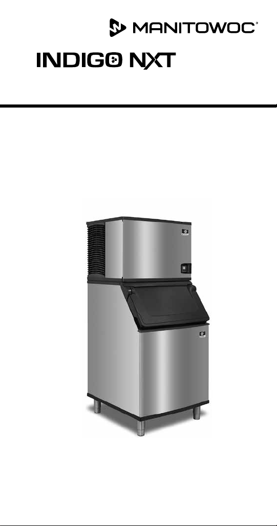
Part Number 000015430 Rev01 5/19
Air/Water/Remote Condenser
Ice Machines
Technician’s Handbook
®
Page 2

Page 3

Safety Notices
Read these precautions to prevent personal injury:
• Read this manual thoroughly before operating,
installing or performing maintenance on the
equipment. Failure to follow instructions in this
manual can cause property damage, injury or death.
• Routine adjustments and maintenance procedures
outlined in this manual are not covered by the
warranty.
• Proper installation, care and maintenance are essential
for maximum performance and trouble-free operation
of your equipment.
• Visit our website www.manitowocice.com for manual
updates, translations, or contact information for
service agents in your area.
This equipment contains high voltage electricity and
refrigerant charge. Installation and repairs are to be
performed by properly trained technicians aware of
the dangers of dealing with high voltage electricity and
refrigerant under pressure. The technician must also
be certified in proper refrigerant handling and servicing
procedures. All lockout and tag out procedures must be
followed when working on this equipment.
• This equipment is intended for indoor use only. Do not
install or operate this equipment in outdoor areas.
• As you work on this equipment, be sure to pay close
attention to the safety notices in this handbook.
Disregarding the notices may lead to serious injury
and/or damage to the equipment.
Page 4
Definitions
DANGER
Indicates a hazardous situation that, if not avoided, will
result in death or serious injury. This applies to the most
extreme situations.
Warning
n
Indicates a hazardous situation that, if not avoided,
could result in death or serious injury.
Caution
,
Indicates a hazardous situation that, if not avoided,
could result in minor or moderate injury.
Notice
Indicates information considered important, but not
hazard-related (e.g. messages relating to property
damage).
NOTE: Indicates useful, extra information about the
procedure you are performing.
Page 5

Warning
n
Follow these electrical requirements during
installation of this equipment.
• All field wiring must conform to all applicable
codes of the authority having jurisdiction. It is
the responsibility of the end user to provide the
disconnect means to satisfy local codes. Refer to
rating plate for proper voltage.
• This appliance must be grounded.
• This equipment must be positioned so that the plug
is accessible unless other means for disconnection
from the power supply (e.g., circuit breaker or
disconnect switch) is provided.
• Check all wiring connections, including factory
terminals, before operation. Connections can
become loose during shipment and installation.
Page 6

Warning
n
Follow these precautions to prevent personal injury
during installation of this equipment:
• Installation must comply with all applicable
equipment fire and health codes with the authority
having jurisdiction.
• Connect to a potable water supply only.
• To avoid instability the installation area must be
capable of supporting the combined weight of the
equipment and product. Additionally the equipment
must be level side to side and front to back.
• Remove all removable panels before lifting and
installing and use appropriate safety equipment
during installation and servicing. Two or more
people are required to lift or move this appliance to
prevent tipping and/or injury.
• Do not damage the refrigeration circuit when
installing, maintaining or servicing the unit.
• This equipment contains refrigerant charge.
Installation of the line sets must be performed by
a properly trained and EPA certified refrigeration
technician aware of the dangers of dealing with
refrigerant charged equipment.
• Ice machines require a deflector when installed on
an ice storage bin. Prior to using a non-OEM ice
storage system with this ice machine, contact the
bin manufacturer to assure their ice deflector is
compatible.
• Prior to installing a non-OEM ice storage system
with this ice machine, follow the manufacturers
installation procedures and verify the location and
installation meets the local/national mechanical
codes and stability requirements.
Page 7

Warning
n
Follow these precautions to prevent personal injury
while operating or maintaining this equipment.
• Refer to nameplate to identify the type of refrigerant
in your equipment.
• Only trained and qualified personnel aware of the
dangers are allowed to work on the equipment.
• Read this manual thoroughly before operating,
installing or performing maintenance on the
equipment. Failure to follow instructions in this
manual can cause property damage, injury or death.
• Crush/Pinch Hazard. Keep hands clear of moving
components. Components can move without
warning unless power is disconnected and all
potential energy is removed.
• Moisture collecting on the floor will create a
slippery surface. Clean up any water on the floor
immediately to prevent a slip hazard.
• Never use sharp objects or tools to remove ice or
frost. Do not use mechanical devices or other means
to accelerate the defrosting process.
• When using cleaning fluids or chemicals, rubber
gloves and eye protection (and/or face shield) must
be worn.
Page 8

Warning
n
Follow these precautions to prevent personal injury
while operating or maintaining this equipment.
• Objects placed or dropped in the bin can affect
human health and safety. Locate and remove any
objects immediately.
• Never use sharp objects or tools to remove ice or
frost.
• Do not use mechanical devices or other means to
accelerate the defrosting process.
• When using cleaning fluids or chemicals, rubber
gloves and eye protection (and/or face shield) must
be worn.
DANGER
Do not operate equipment that has been misused,
abused, neglected, damaged, or altered/modified
from that of original manufactured specifications. This
appliance is not intended for use by persons (including
children) with reduced physical, sensory or mental
capabilities, or lack of experience and knowledge,
unless they have been given supervision concerning
use of the appliance by a person responsible for their
safety. Do not allow children to play with, clean or
maintain this appliance without proper supervision.
Page 9

Warning
n
Follow these precautions to prevent personal injury
during use and maintenance of this equipment:
• It is the responsibility of the equipment owner to
perform a Personal Protective Equipment Hazard
Assessment to ensure adequate protection during
maintenance procedures.
• Do Not Store Or Use Gasoline Or Other Flammable
Vapors Or Liquids In The Vicinity Of This Or Any
Other Appliance. Never use flammable oil soaked
cloths or combustible cleaning solutions for
cleaning.
• All covers and access panels must be in place and
properly secured when operating this equipment.
• Risk of fire/shock. All minimum clearances must be
maintained. Do not obstruct vents or openings.
• Failure to disconnect power at the main power
supply disconnect could result in serious injury or
death. The power switch DOES NOT disconnect all
incoming power.
• All utility connections and fixtures must be
maintained in accordance with the authority having
jurisdiction.
• Turn off and lockout all utilities (gas, electric, water)
according to approved practices during maintenance
or servicing.
Page 10

DANGER
Follow these flammable refrigeration system
requirements during installation, use or repair of this
equipment.
• Refer to nameplate - Ice machine models may
contain up to 150 grams of R290 (propane)
refrigerant. R290 (propane)is flammable in
concentrations of air between approximately 2.1%
and 9.5% by volume (LEL lower explosion limit and
UEL upper explosion limit). An ignition source at
a temperature higher than 470°C is needed for a
combustion to occur. Refer to nameplate to identify
the type of refrigerant in your equipment.
• To minimize the risk of ignition due to improper
installation, replacement parts or service
procedures, only refrigeration technicians with
flammable refrigerant training who are aware of the
dangers of dealing with high voltage electricity and
refrigerant under pressure are allowed to work on
this equipment.
• All replacement parts must be like components
obtained from the equipment manufacturers
authorized replacement part network.
• This equipment must be installed in accordance with
the ASHRAE 15 Safety Standard for Refrigeration
Systems.
• This equipment can not be installed in corridors or
hallways of public buildings.
• Installation must comply with all applicable
equipment fire and health codes with the authority
having jurisdiction.
Page 11

DANGER
Follow these flammable refrigeration system
requirements during installation, use or repair of this
equipment.
• All lockout and tag out procedures must be followed
when working on this equipment.
• This equipment contains high voltage electricity
and refrigerant charge. Shorting electrical wires to
refrigeration tubing may result in an explosion. All
electrical power must be disconnected from the
system before servicing the system. Refrigerant
leaks, can result in serious injury or death from
explosion, fire, or contact with refrigerant or
lubricant mists.
• Do not damage the refrigeration circuit when
installing, maintaining or servicing the unit. Never
use sharp objects or tools to remove ice or frost.
Do not use mechanical devices or other means to
accelerate the defrosting process.
Page 12

Warning
n
Follow these precautions to prevent personal injury
during use and maintenance of this equipment:
• Units with two power cords must be plugged into
individual branch circuits. During movement, cleaning
or repair it is necessary to unplug both power cords.
• Never use a high-pressure water jet for cleaning on
the interior or exterior of this unit. Do not use power
cleaning equipment, steel wool, scrapers or wire
brushes on stainless steel or painted surfaces.
• Two or more people are required to move this
equipment to prevent tipping.
• Locking the front casters after moving is the owner’s
and operator’s responsibility. When casters are
installed, the mass of this unit will allow it to move
uncontrolled on an inclined surface. These units must
be tethered/secured to comply with all applicable
codes.
• The on-site supervisor is responsible for ensuring that
operators are made aware of the inherent dangers of
operating this equipment.
• Do not operate any appliance with a damaged cord
or plug. All repairs must be performed by a qualified
service company.
Page 13

Table of Contents
General Information
Model Numbers................................ 19
Air-Water-Remote Condenser Models ......19
Model Nomenclature........................... 20
Ice Cube Sizes ..................................21
Model/Serial Number Location ................. 21
Warranty ......................................22
Warranty Registration....................22
LuminIce® II....................................23
Installation
Location of Ice Machine ........................ 25
Clearance Requirements........................26
Air, Water, Remote Condenser Models ......26
Ice Machine Heat of Rejection ..................27
Installation on a Bin ............................ 27
Ice Machine on a Dispenser Installation.........28
Water Supply and Drains ....................... 29
Line set Applications ...........................30
Remote Condenser ......................31
Remote Ice Machine Usage with Non-Manitowoc
Multi-Circuit Condensers .......................34
Part Number 000015430 Rev01 5/19 11
Page 14

Maintenance
Cleaning and Sanitizing......................... 37
IAUCS® ................................38
Touchscreen Operation For The Clean Cycle .....39
Starting a clean cycle ....................39
Water curtain/damper operation during the
clean cycle .............................39
Pausing a clean cycle.....................39
Power interruption during clean cycle ......39
Aborting a clean cycle....................39
Cleaning Procedure......................40
Sanitizing Procedure .....................45
Preventative Maintenance Cleaning Procedure..48
Removal from Service/Winterization............ 50
Air-Cooled Ice Machines..................50
Water-cooled Ice Machines ...............51
Operation
Touch Screen Features.......................... 53
Home screen icon descriptions ............55
Setup Wizard ..................................57
Menu Navigation Overview..................... 58
Settings Menu Screen Navigation ..........58
Operational Checks.............................63
General................................63
Ice Thickness Check......................64
Sequence of Operation ........................66
Self Contained Air or Water Cooled.........66
Energized Parts Chart Self contained Air or
water-Cooled Models ....................70
Remote Condenser ......................72
Energized Parts Chart Remote Air-Cooled
Condenser Models ......................76
12 Part Number 000015430 Rev01 5/19
Page 15

Troubleshooting
Troubleshooting .............................. 79
Event Log ..............................80
Event Log Detail.........................81
Thaw Cycle.............................86
Safe Operation Mode ....................87
E01 Long Freeze Cycle....................88
E02 Long Harvest Cycle...................88
Analyzing Why A Service Fault (E01 & E02)
Stopped the Ice Machine .................88
E01 Long Freeze.........................89
E02 Long Harvest........................90
Troubleshooting By Symptom................... 91
Reset To Factory Defaults .................92
Symptom #1 Ice Machine Will Not Run......93
Symptom #2 - Freeze Cycle Refrigeration
System Operational Analysis Tables.........98
Symptom #3 & #4 Harvest Problems
Self-contained Air, Water & Remote Condenser
Models ...............................127
Symptom #3 - Remote Condenser.........130
Symptom #4 Self-Contained Air, Water-Cooled
Or Remote ............................132
Part Number 000015430 Rev01 5/19 13
Page 16

Component Check Procedures
Electrical Components.........................135
Control Board, Display And Touchscreen ...135
Control Board Relay Test.................138
Programming A Replacement Control Board 139
USB Flash Drive Specifications and Formatting .
.....................................140
Exporting Data to a Flash Drive ...........141
Upgrading Firmware with a Flash Drive ....142
Main Fuse ............................143
Bin Switch ............................144
Water Level Control Circuitry .............147
Ice Thickness Probe (Initiates Harvest) .....150
Bin Level Probe ...............................154
Normal Operation ......................154
Troubleshooting: .......................155
Thermistors...................................156
High Pressure Cutout (HPCO) Control ......160
Fan Cycle Control.......................163
Harvest Assist Air Pump .................164
Compressor Electrical Diagnostics.........165
Diagnosing Start Components ............167
Refrigeration Components.....................170
Head Pressure Control Valve .............170
Harvest Pressure Regulating (HPR) System
Remote Condenser Only.................174
Water Regulating Valve..................177
Refrigerant Recovery/Evacuation ..............178
Definitions ............................178
Refrigerant Re-Use Policy ................179
Self-Contained Model Procedure .........181
Remote Condenser Model Procedure......185
System Contamination Clean-Up...............189
Determining Severity Of Contamination....189
Cleanup Procedure .....................191
Liquid Line Filter-Driers..................195
Replacing Pressure Controls Without Removing
Refrigerant Charge .....................196
Total System Refrigerant Charge ..........197
14 Part Number 000015430 Rev01 5/19
Page 17

Charts
Cycle Times/24-Hour Ice Production/ Refrigerant
Pressure Charts ...............................199
IF0300 Series . . . . . . . . . . . . . . . . . . . . . . . . . .200
IT0420 Series ..........................202
IT0450 Series ..........................204
IT0500 Series ..........................206
IF0600 Series . . . . . . . . . . . . . . . . . . . . . . . . . .209
IT0620 Series ..........................212
IT0750 series ..........................214
IF0900 Series . . . . . . . . . . . . . . . . . . . . . . . . . .216
IT1500 Series ..........................222
IT1900 Series ..........................225
Diagrams
Wiring Diagrams ..............................229
Wiring Diagram Legend .................229
IF0300/IT0420/IT0450/IT0500/IT0620/IT0750
1ph Air/Water .........................230
IT0500 - 1ph Remote Air-Cooled ..........232
IF0600/IF0900/IT1200/IT1500/IT1900 - 1ph
Air/Water.............................234
IF0600/IF0900/IT1200/IT1500/IT1900 - 3ph
Air/Water.............................236
IT1200/IT1500/IT1900 1ph Remote . . . . . . .238
IT1200/IT1500/IT1900 - 3ph Remote
Condenser ............................240
Electronic Control Board.......................242
Electrical Noise Filter ...................244
Refrigeration Tubing Schematics ...............245
Self-Contained Air or Water-Cooled .......245
Remote Air-Cooled Condenser Models.....249
Part Number 000015430 Rev01 5/19 15
Page 18

THIS PAGE INTENTIONALLY LEFT BLANK
16 Part Number 000015430 Rev01 5/19
Page 19
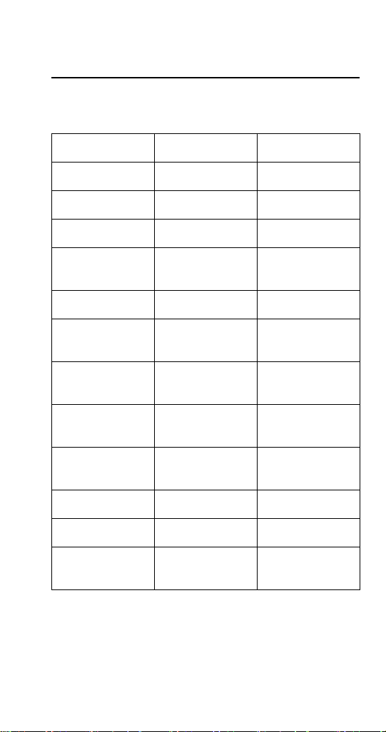
Model Numbers
IDF0300A
IYF0300A
IDT0420A
IYT0420A
IDT0450A
IYT0450A
IDT0500A
IYT0500A
IRT0500A
IDF0600A
IYF0600A
IDT0620A
IYT0620A
IRT0620A
IDT0750A
IYT0750A
IRT0750A
IDF0900A
IYF0900A
IRF0900A
IDT0900A
IYT0900A
IRT0900A
IDT1200A
IYT1200A
IDT1500A
IYT1500A
IDT1900A
IYT1900A
IRT1900A
IDF0300W
IYF0300W
IDT0420W
IYT0420W
IDT0450W
IYT0450W
IDT0500W
IYT0500W
IRT0500W
IDF0600W
IYF0600W
IDT0620W
IYT0620W
IRT0620W
IDT0750W
IYT0750W
IRT0750W
IDF0900W
IYF0900W
IRF0900W
IDT0900W
IYT0900W
IRT0900W
IDT1200W
IYT1200W
IDT1500W
IYT1500W
IDT1900W
IYT1900W
----
----
----
----
----
----
---IDT0500N
IYT0500N
---IDF0600N
IYF0600N
----
----
----
----
----
---IDF0900N
IYF0900N
---IDT0900N
IYT0900N
---IDT1200N
IYT1200N
IDT1500N
IYT1500N
IDT1900N
IYT1900N
IRT1900N
NOTE: Additional designators are used to identify Voltage, Specials
or Country specific models - See “Model Nomenclature” on page
18
Part Number 000015430 Rev01 5/19 17
Page 20

C Countertop
ELECTRICAL
I Y
r
Australia
AAlternate Compresso
SPECIAL USE
463 = 460/60/3
Blank general use
Qcoated condenser
H high pressure
Zcord without plug
B NEMA plug (USA)
Fschuko plug (EU)
261 = 208-230/60/1
251 = 220-240/50/1 (S=230)
2= 22" wide cabinet
#= all other #s mean
P R290 (propane)
F R404A (four)
T R410A (ten)
G 13A blade (GBR)
263 = 208-230/60/3
producon value
B R600A (butane)
I oblique V blades
271 = 200/50-60/1
E R134A (eight)
273 = 200/50-60/3
453 = 380-415/50/3
POWER CORD OPTION
Blank juncon box
CONFIGURATION
161 = 115/60/1
REFRIGERANT TYPE
(AUS)
Mmarine
Pcorreconal
L lever
XLuminice/Sanitaon
Ttop air discharge
V space maker
CONDENSER TYPE
NOMINAL PRODUCTION @ 70/50
MARKET IDENTIFIER
Aair cooled
Wwater cooled
0300 produces ~300 #/day
0320 produces ~300 #/day
Blank not market specific
SSaudi Arabia (GCC)
K Korea (KC)
C China (CCC)
D Germany (GS)
N Brazil (InMetro)
(tradional)
C CVD (remote)
N remote
Soo is stated in kg/day
0350 produces ~350 #/day
etc. . .
T1 5 0 0 N –2 6 1 X
ICE MACHINE SERIES
I Indigo
U Undercounter
KKoolaire
RFlake/Nugget
B Big shot
SS-series
IB Ice Beverage
ICE TYPE
RRegular
DDice
Y Half-dice
F Flake
NNugget
G Gourmet
Blank for IB only
18 Part Number 000015430 Rev01 5/19
Page 21
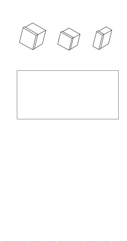
Regular
1-1/8" x 1-1/8" x 7/8"
2.86 x 2.86 x 2.22 cm
All Manitowoc ice machines require the ice storage
system (bin, dispenser, etc.) to incorporate an ice
deflector.
Prior to using a non-Manitowoc ice storage system
with other Manitowoc ice machines, contact the
manufacturer to assure their ice deflector is compatible
with Manitowoc ice machines.
Dice
7/8" x 7/8" x 7/8"
2.22 x 2.22 x2.22 cm
n
Half Dice
3/8" x 1-1/8" x 7/8"
0.95 x 2.86 x 2.22 cm
These numbers are required when requesting information
from your local Manitowoc Distributor, service
representative, or Manitowoc Ice.
• The model and serial number can be viewed by pressing
the information icon on the touchscreen.
• The owner warranty registration card.
• The model/serial number data plate located in the
evaporator compartment and on the back of the ice
machine.
The model and serial number displayed on the touchscreen
must match the data plate for proper operation.
Part Number 000015430 Rev01 5/19 19
Page 22
For warranty information visit:
www.manitowocice.com/Service/Warranty
• Warranty Coverage Information
• Warranty Registration
• Warranty Verification
Warranty coverage begins the day the ice machine is
installed.
Completing the warranty registration process is a quick and
easy way to protect your investment.
Scan the QR code with your smart device or enter the link
in a web browser to complete your warranty registration.
Registering your product insures warranty coverage and
streamlines the process if any warranty work is required.
20 Part Number 000015430 Rev01 5/19
Page 23

The LuminIce® growth inhibitor recirculates the air in the
ice machine foodzone over a UV bulb. This process will
inhibit the growth of common micro-organisms on all
exposed foodzone surfaces.
• LuminIce® bulbs require replacement on a yearly basis.
• The control board can be set to automatically display a
reminder after 12 months.
NOTE: LuminIce® and LuminIce® II bulbs are not
interchangeable; verify your model before ordering a
replacement bulb.
Cleanup Procedure for Accidental Bulb Breakage
The cleanup procedure is identical to the procedure used
to clean up compact fluorescent (CFL) or fluorescent tube
lights. These lights contain a small amount of mercury
sealed within a glass tube. Breaking these types of lights
will release mercury and mercury vapor. The broken bulb
can continue to release mercury vapor until it is cleaned up
and removed.
The latest EPA procedures can be viewed on their website
at www.epa.gov/cfl/cflcleanup.html.
NOTE: LuminIce® and LuminIce® II bulbs are not
interchangeable; verify your model before ordering a
replacement bulb. LuminIce® bulbs have a white base and
LuminIce® II bulbs have a blue base.
Part Number 000015430 Rev01 5/19 21
Page 24

THIS PAGE INTENTIONALLY LEFT BLANK
22 Part Number 000015430 Rev01 5/19
Page 25

Installation
Location of Ice Machine
The location selected for the ice machine must meet the
following criteria. If any of these criteria are not met,
select another location.
• The location must be free of airborne and other
contaminants.
• Self contained air cooled, water cooled or head section
for remote air cooled condenser models - The air
temperature must be at least 35°F (1.6°C), but must
not exceed 110°F (43.4°C).
• Remote air cooled condenser - The air temperature
must be at least -20°F (-29°C), but must not exceed
120°F (49°C)
• Ice Making Water Inlet - Water Pressure must be at
least 20 psi (1.38 bar), but must not exceed 80 psi
(5.52 bar).
• Condenser Water Inlet - Water Pressure must be at
least 20 psi (1.38 bar), but must not exceed 276 psi
(19 bar).
• The location must not be near heat-generating
equipment or in direct sunlight and protected from
weather.
• The location must not obstruct air flow through or
around the ice machine. Refer to chart below for
clearance requirements.
• The ice machine must be protected if it will be
subjected to temperatures below 32°F (0°C). Failure
caused by exposure to freezing temperatures is not
covered by the warranty. See “Removal from Service/
Winterization”
Part Number 000015430 Rev01 5/19 23
Page 26
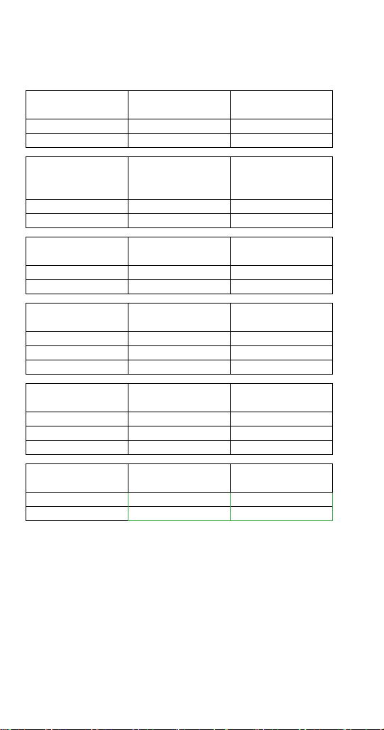
Clearance Requirements
AIR, WATER, REMOTE CONDENSER MODELS
IF0300 Self-Contained
Air-Cooled
Top/Sides 16” (40 cm) 8” (20 cm)
Back 5” (13 cm) 5” (13 cm)
IT0420 IT0450
IT0500 IF0600
IT0620 IT0750
Top/Sides 12" (30.5 cm) 8" (20.3 cm)
Back 5" (12.7 cm) 5" (12.7 cm)
IF0900 IT0900 Self-Contained
Top/Sides 8” (20.3 cm) 8” (20.3 cm)
Back 5” (13 cm) 5” (13 cm)
IT1200
Top 8" (20.3 cm) 8" (20.3 cm)
Sides 12” (30.5 cm) 8” (20.3 cm)
Back 5" (12.7 cm) 5" (12.7 cm)
IT1500
Top 12” (30.5 cm) 8" (20.3 cm)
Sides 8” (20.3 cm) 8” (20.3 cm)
Back 5” (12.7 cm) 5" (12.7 cm)
IT1900
Top/Sides 24” (61 cm) 8" (20.3 cm)
Back 12” (30.5 cm) 5" (12.7 cm)
Self-Contained
Air-Cooled
Air-Cooled
Self-Contained
Air-Cooled
Self-Contained
Air-Cooled
Self-Contained
Air-Cooled
Water-Cooled
Water-Cooled and
Water-Cooled and
Water-Cooled
and Remote
Water-Cooled
and Remote
Water-Cooled
and Remote
Remote
Remote
Top Air Discharge Kit
The top air discharge kit can be used on select ice machine
models. This kit directs warm exhaust air upward rather than out
the side panels. Top air discharge kits require the same clearance
requirements as the comparable self-contained air-cooled model.
Contact your local distributor for details.
24 Part Number 000015430 Rev01 5/19
Page 27

Ice Machine Heat of Rejection
Series Ice
Machine
IF0300 4600 5450
IT0420 3800 6000
IT0450 3800 6000
IT0500 3800 6000
IF0600 11800 13700
IT0620 5400 6300
IT0750 12800 13700
IF0900 13000 16000
IT0900 12700 14800
iT1200 16200 19100
IT1500 23000 27000
IT1900 26100 30500
*BTU/Hour
Because the heat of rejection varies during the ice making cycle,
the figure shown is an average.
Air Conditioning* Peak
Heat of Rejection
Installation on a Bin
An ice deflector is required for all bin installations and is
included with all Manitowoc bins. Order the appropriate
deflector kit (30" or 48") for any bin without a deflector.
NOTE: An optional safety kit is available to attach the ice
machine to D model bins. Contact your local distributor for
details.
Warning
n
PERSONAL INJURY POTENTIAL
Do not operate any ice machine with the deflector
removed.
Part Number 000015430 Rev01 5/19 25
Page 28

Ice Machine on a Dispenser Installation
Observe the following recommendations unless required
by the dispenser manufacturer.
Refer to the standard equipment price list at
www.manitowocice.com for adapter, deflector or ice
management accessories.
• An adapter is not required for ice machines that match
the dispenser size.
• A deflector is not required.
• Ice level management is recommended to prevent
water leakage or movement of ice machine during
agitation.
• A dispenser baffle is required to prevent ice from
contacting the ice machine door and prevent possible
water leakage.
• Align sides and back of ice machine with sides and
back of dispenser when placing ice machine.
• Follow ice machine installation procedures in this
manual and any additional installation requirements
specified by the dispenser manufacturer.
26 Part Number 000015430 Rev01 5/19
Page 29

Water Supply and Drains
Potable Water
• Water temperature must be between
40°F (4.4°C) and 90°F (32°C).
• Water pressure must be between
20 psi (140 kPa) and 80 psi (550 kPa).
• Minimum internal diameter of tubing 3/8” (10mm).
Drain Connections
• Drain lines must have a 1.5 inch drop per 5 feet (2.5
cm per meter) of run and must not create traps.
• The floor drain must be large enough to accommodate
drainage from all drains.
• Run separate bin and ice machine drain lines.
• Insulate drain lines to prevent condensation.
• Vent the ice machine drain to the atmosphere.
• Drain termination must have an air gap that meets
local code.
Auxiliary Base Drain Installation
An auxiliary drain is located in the ice machine base to
remove moisture in high humidity areas.
1. View the back of the ice machine base on the
compressor side and locate and remove the cap plug.
2. Route tubing to an open site drain:
• Use 1/2 inch CPVC tubing.
• Apply a bead of silicone around the exterior of the ice
machine tubing and insert into ice machine base. The
silicone will secure the tubing and provide a watertight
seal.
• Provide support for tubing.
Part Number 000015430 Rev01 5/19 27
Page 30

Line set Applications
Warning
n
The 60-month compressor warranty (including the
36-month labor replacement warranty) will not
apply if the Manitowoc Ice Machine, Condenser or
QuietQube® Condensing Unit were not installed
according to specifications. This warranty also will
not apply if the refrigeration system is modified with
a condenser, heat reclaim device, or other parts or
assemblies not manufactured by Manitowoc Ice. Or
refrigeration system additives such as leak detection
dyes, inhibitors or non OEM approved chemicals.
Caution
,
Recovery locations vary by model. Verify you are
making the correct connections for your model to
prevent accidental release of high pressure refrigerant.
Important
Manitowoc remote systems are only approved and
warranted as a complete new package. Warranty on
the refrigeration system will be void if new equipment
is connected to existing (used) tubing, remote
condenser, remote condensing unit or ice machine
head section.
28 Part Number 000015430 Rev01 5/19
Page 31
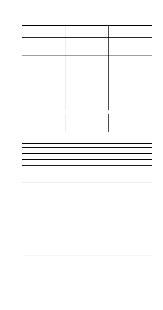
REMOTE CONDENSER
Ice Machine
IT0500N JCT0500
IF0600N
IF0900N
IT0900 IT1200N JCT1200
IT1500N
IT1900N
*Line Set Discharge Line Liquid Line
RT 1/2" (1.27 cm) 5/16" (.79 cm)
RL 1/2" (1.27 cm) 3/8" (.95 cm)
R404A line sets have white protective caps.
R410A line sets have pink protective caps.
Air Temperature Around the Condenser
Minimum Maximum
-20°F (-29°C) 120°F (49°C)
Remote Single
Circuit Condenser
JCF0900
JCT1500
Line Set*
RT-20-R410A
RT-35-R410A
RT-50-R410A
RT-20-R404A
RT-35-R404A
RT-50-R404A
RT-20-R410A
RT-35-R410A
RT-50-R410A
RL-20-R410A
RL-35-R410A
RL-50-R410A
Additional Refrigerant Charge For 51' to 100' Line Sets
Ice Machine Condenser Additional Amount of
Refrigerant To Be Added To
Nameplate Charge
IT0500N JCT0500 1.5 lbs - 680g
IF0600N JCF0900 1.5 lbs - 680g
IF0900N JCF0900 2.0 lbs - 907g
IT0900N
IT1200N
IF0600N JCF0900 1.5 lbs - 680 g
IF0900N JCF0900 2.0 lbs - 907 g
IT1500N
IT1900N
JCT1200 2.0 lbs - 907g
JCT1500 2.0 lbs - 907g
Part Number 000015430 Rev01 5/19 29
Page 32
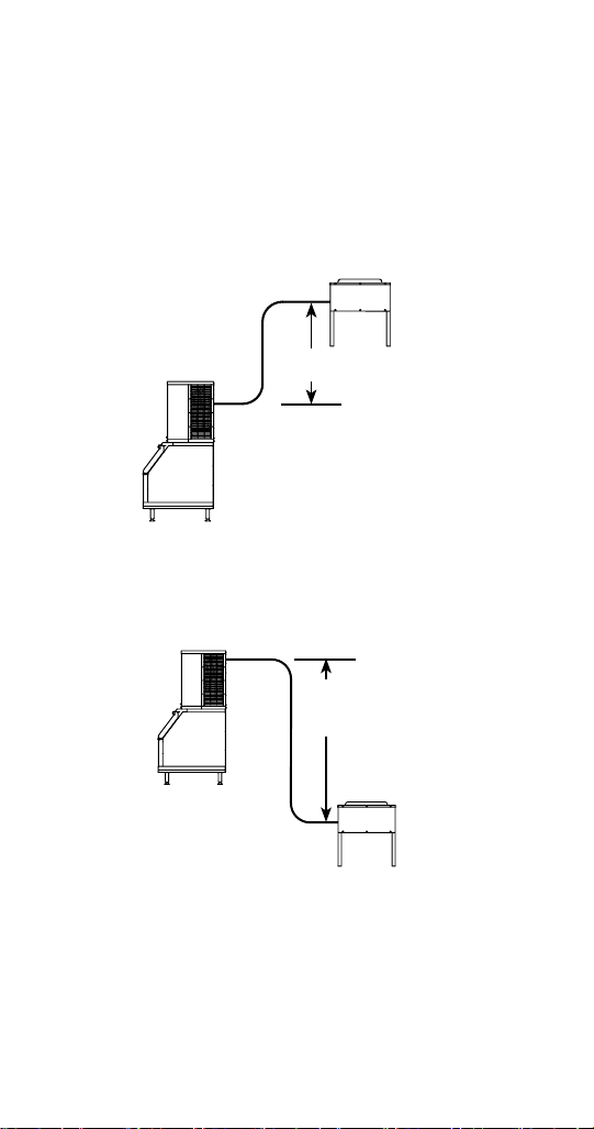
Calculating Allowable Line set Distance
Line Set Length
The maximum length is 100' (30.5 m).
Line Set Rise/Drop
The maximum rise is 35' (10.7 m).
The maximum drop is 15' (4.5 m).
35 FT. (10.7 M)
MAXIMUM DISTANCE
35 ft. (10.7 m) Rise: The maximum distance the
Condenser or Condensing Unit can be above the ice
machine.
15 FT. (4.5 M)
MAXIMUM
DISTANCE
15 ft. (4.5 m) Drop: The maximum distance the Condenser
or Condensing Unit can be below the ice machine.
30 Part Number 000015430 Rev01 5/19
Page 33

Calculated Line Set Distance
The maximum calculated distance is 150' (45.7 m).
Line set rises, drops, horizontal runs (or combinations
of these) in excess of the stated maximums will exceed
compressor start-up and design limits. This will cause poor
oil return to the compressor.
Make the following calculations to make sure the line set
layout is within specifications.
1. Insert the measured rise into the formula below.
Multiply by 1.7 to get the calculated rise.
(Example: A condenser located 10 feet above the ice
machine has a calculated rise of 17 feet.)
2. Insert the measured drop into the formula below.
Multiply by 6.6 to get the calculated drop.
(Example. A condenser located 10 feet below the ice
machine has a calculated drop of 66 feet.)
3. Insert the measured horizontal distance into the
formula below. No calculation is necessary.
4. Add together the calculated rise, calculated drop,
and horizontal distance to get the total calculated
distance. If this total exceeds 150' (45.7 m), move
the condenser to a new location and perform the
calculations again.
Maximum Line set Distance Formula
Measured Rise ____ X 1.7 = ______Calculated Rise
(35 ft. Max)
Step 1
Measured Drop ____ X 6.6 = ______Calculated Drop
(15 ft. Max.)
Step 2
Measured Horizontal Distance = _________ Horizontal
(100 ft. Max.) Distance
Step 3
Total Calculated Distance = ___________ Total Calculated
(150 ft. Max.) Distance
Part Number 000015430 Rev01 5/19 31
Page 34

Remote Ice Machine Usage with NonManitowoc Multi-Circuit Condensers
Warranty
The sixty (60) month compressor warranty, including thirty
six (36) month labor replacement warranty, shall not apply
when the remote ice machine is not installed within the
remote specifications. The foregoing warranty shall not
apply to any ice machine installed and/or maintained
inconsistent with the technical instructions provided
by Manitowoc Ice. Performance may vary from Sales
specifications. ARI certified standard ratings only apply
when used with a Manitowoc remote condenser.
If the design of the condenser meets the specifications,
Manitowoc’s only approval is for full warranty coverage
to be extended to the Manitowoc manufactured part of
the system. Since Manitowoc does not test the condenser
in conjunction with the ice machine, Manitowoc will not
endorse, recommend, or approve the condenser, and will
not be responsible for its performance or reliability.
Important
Manitowoc warrants only complete new and unused
remote packages. Guaranteeing the integrity of a new
ice machine under the terms of our warranty prohibits
the use of pre-existing (used) tubing or condensers.
32 Part Number 000015430 Rev01 5/19
Page 35
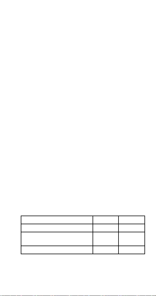
Design & Burst Pressure
Design Pressure 600 psig - 4137 kPa
Burst Pressure 2500 psig - 17237 kPa
Head Pressure Control Valve
Do not use a fan cycling control to try to maintain
discharge pressure. Compressor failure will result. Any
remote condenser connected to a Manitowoc Ice Machine
must have the OEM head pressure control valve installed.
Manitowoc will not accept substitute “off the shelf” head
pressure control valves.
Kits are available for head pressure control installation:
• R404A Refrigerant - K00479
• R410A Refrigerant - K00221
Fan Motor
The condenser fan must be on during the complete ice
machine freeze cycle (do not cycle on fan cycle control).
The ice maker has a condenser fan motor circuit for use
with a Manitowoc condenser. It is recommended that
this circuit be used to control the condenser fan(s) on the
multi-circuit condenser to assure it is on at the proper
time. Do not exceed the rated amps for the fan motor
circuit listed on the ice machine’s serial tag.
Internal Condenser Volume
The multi-circuit condenser internal volume must not
be less than or exceed that used by Manitowoc. Do
not exceed internal volume and try to add charge to
compensate, as compressor failure will result.
Model Minimum Maximum
IT0500N 0.020 0.030
IF0600/IF0900N
IT0900N/IT1200N
IT1500N/IT1900N/IF0900 0.085 0.105
Part Number 000015430 Rev01 5/19 33
0.045 0.060
Page 36

Heat of Rejection
Model Peak Average
IT0500N 3800 6000
IF0600 11800 13000
IF0900/IT0900 13000 16000
IT1200N 16200 19100
IT1500N 23000 27000
IT1900N 26100 30500
Refrigerant Charge
The ice machine model/serial tag lists the refrigerant
amount. Remote condensers and line sets contain a vapor
charge only.
Quick Connect Fittings
The ice machine and line sets come with quick connect
fittings. It is recommended that matching quick connects
(available through Manitowoc Distributors K00129) be
installed in the multi-circuit condenser, and that a vapor
“holding” charge, 5 oz. (150 ml), of proper refrigerant be
added to the condenser prior to connection of the ice
machine or line set to the condenser.
34 Part Number 000015430 Rev01 5/19
Page 37

Maintenance
Cleaning and Sanitizing
General
You are responsible for maintaining the ice machine
in accordance with the instructions in this manual.
Maintenance procedures are not covered by the warranty.
Clean and sanitize the ice machine a minimum of once
every six months for efficient operation. If the ice machine
requires more frequent cleaning and sanitizing, consult
a qualified service company to test the water quality and
recommend appropriate water treatment. An extremely
dirty ice machine must be taken apart for cleaning and
sanitizing.
Manitowoc Ice Machine Cleaner and Sanitizer are the only
products approved for use in Manitowoc ice machines.
Caution
,
Use only Manitowoc approved Ice Machine Cleaner
and Sanitizer for this application (Manitowoc Cleaner
part number 9405463 and Manitowoc Sanitizer part
number 9405653). It is a violation of Federal law to
use these solutions in a manner inconsistent with their
labeling. Read and understand all labels printed on
bottles before use.
Caution
,
Do not mix Cleaner and Sanitizer solutions together. It
is a violation of Federal law to use these solutions in a
manner inconsistent with their labeling.
Warning
n
Wear rubber gloves and safety goggles (and/or face
shield) when handling Ice Machine Cleaner or Sanitizer.
Part Number 000015430 Rev01 5/19 35
Page 38

Cleaning/Sanitizing Procedure
This procedure must be performed a minimum of once
every six months.
• The ice machine and bin must be disassembled
cleaned and sanitized.
• All ice produced during the cleaning and sanitizing
procedures must be discarded.
• Removes mineral deposits from areas or surfaces that
are in direct contact with water.
Preventative Maintenance Cleaning Procedure
• This procedure cleans all components in the water
flow path, and is used to clean the ice machine
between the bi-yearly cleaning/sanitizing procedure.
IAUCS®
iAuCS® does not operate when the Clean button is used to
start a clean cycle. To prime the hose, activation is required
through the Service Menu/iAuCS® icon.
Exterior Cleaning
Clean the area around the ice machine as often as
necessary to maintain cleanliness and efficient operation.
Wipe surfaces with a damp cloth rinsed in water to remove
dust and dirt from the outside of the ice machine. If a
greasy residue persists, use a damp cloth rinsed in a mild
dish soap and water solution. Wipe dry with a clean, soft
cloth.
The exterior panels have a clear coating that is stain
resistant and easy to clean. Products containing abrasives
will damage the coating and scratch the panels.
• Never use steel wool or abrasive pads for cleaning.
• Never use chlorinated, citrus based or abrasive
cleaners on exterior panels and plastic trim pieces.
36 Part Number 000015430 Rev01 5/19
Page 39

Touchscreen Operation For The Clean Cycle
STARTING A CLEAN CYCLE
Pressing the clean icon will display a Continue/Abort
screen, and a warning that pressing Continue will result in
a clean cycle that can last up to 35 minutes.
WATER CURTAIN/DAMPER OPERATION DURING THE CLEAN CYCLE
The water curtain/damper must remain closed during the
clean sequence. When the curtain/damper is open for
more than 3 seconds the clean cycle stops and a message
is displayed on the touchscreen with a choice to continue
or stop the clean cycle. Stopping the clean cycle will result
in a series of rinse and dump cycles to verify cleaner or
sanitizer has been removed before ice making.
PAUSING A CLEAN CYCLE
The clean cycle can be paused and resumed at any time
by pressing the on/off button. The clean cycle will resume
from the beginning of either the wash or rinse cycle
depending on the point of interruption.
POWER INTERRUPTION DURING CLEAN CYCLE
If the power supply is interrupted during the clean cycle
the state is retained in the circuit board. When power is
reapplied the clean cycle will resume from the beginning
of either the wash or rinse cycle depending on the point of
interruption
ABORTING A CLEAN CYCLE
Verify cleaner/sanitizer is not present in the water system
before aborting a clean cycle.
1. Press and hold the Clean button, then press and
release the On/Off button.
2. Release the Clean button and select abort from the
touchscreen.
Part Number 000015430 Rev01 5/19 37
Page 40

Cleaning / Sanitizing Procedure
Caution
,
Use only Manitowoc approved Ice Machine Cleaner
and Sanitizer for this application (Manitowoc Cleaner
part number 9405463 and Manitowoc Sanitizer part
number 9405653). It is a violation of Federal law to
use these solutions in a manner inconsistent with their
labeling. Read and understand all labels printed on
bottles before use.
CLEANING PROCEDURE
Caution
,
Do not mix Cleaner and Sanitizer solutions together. It
is a violation of Federal law to use these solutions in a
manner inconsistent with their labeling.
Warning
n
Wear rubber gloves and safety goggles (and/or face
shield) when handling Ice Machine Cleaner or Sanitizer.
Ice machine cleaner is used to remove lime scale and
mineral deposits. Ice machine sanitizer disinfects and
removes algae and slime.
NOTE: Although not required and dependent on your
installation, removing the ice machine top cover may allow
easier access.
38 Part Number 000015430 Rev01 5/19
Page 41

Step 1 Open the front door to access the evaporator
compartment. Ice must not be on the evaporator during
the clean/sanitize cycle. Follow one of the methods below:
• Press the power switch at the end of a harvest cycle
after ice falls from the evaporator(s).
• Press the power switch and allow the ice to melt
• Use the touchscreen to initiate a manual harvest cycle.
Caution
,
Never use anything to force ice from the evaporator.
Damage may result.
Step 2 Remove all ice from the bin/dispenser.
Step 3 Press the Clean button and select “Turn off
when complete”. Water will flow through the water dump
valve and down the drain. Wait approximately 1 minute
until the water trough refills and the display indicates Add
Chemical. Add the proper amount of ice machine cleaner
to the water trough by pouring between the water curtain
and evaporator, then confirm the chemical was added.
NOTE: There is a 10 minute time limit to confirm chemical
was added.
• Confirmation is pushed within 10 minutes - The ice
machine will start a 10 minute wash cycle, followed by
6 rinse and flush cycles.
• Confirmation is not pushed within 10 minutes - The ice
machine will skip the 10 minute wash cycle and start 6
rinse and flush cycles.
Model Amount of Cleaner
IF0300/IT0420/IT0620 3 ounces (90 ml)
IT0450/IT0500/IF0600/IT0750
IF0900/IT0900/IT1200
IT1500/IT1900 9 ounces (265 ml)
5 ounces (150 ml)
Part Number 000015430 Rev01 5/19 39
Page 42
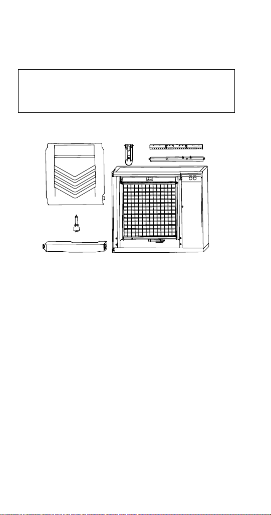
Step 4 Wait until the clean cycle is complete, then
disconnect power to the ice machine (and dispenser when
used).
Warning
n
Disconnect the electric power to the ice machine at
the electric service switch box.
Step 5 Remove parts for cleaning.
E
D
A
C
B
A. Remove the water curtain
• Gently flex the curtain in the center and remove it
from the right side.
• Slide the left pin out.
B. Remove the water trough
• Depress tabs on right and left side of the water trough.
• Allow front of water trough to drop as you pull forward
to disengage the rear pins.
40 Part Number 000015430 Rev01 5/19
Page 43

C. Remove the water level probe
• Pull the water level probe straight down to disengage.
• Lower the water level probe until the wiring connector
is visible.
• Disconnect the wire lead from the water level probe.
• Remove the water level probe from the ice machine.
D. Remove the ice thickness probe
• Compress the hinge pin on the top of the ice thickness
probe.
• Pivot the ice thickness probe to disengage one pin
then the other. The ice thickness probe can be cleaned
at this point without complete removal. If complete
removal is desired, disconnect the ice thickness control
wiring from the control board.
E. Remove the water distribution tube
NOTE: Distribution tube thumbscrews are retained
to prevent loss. Loosen thumbscrews but do not pull
thumbscrews out of distribution tube.
• Loosen the two outer screws (do not remove screws
completely they are retained to prevent loss) and pull
forward on the distribution tube to release from slip
joint.
Disassemble distribution tube by loosening the two (2)
middle thumbscrews and dividing the distribution tube
into two pieces. Please refer to the proper parts removal
for your ice machine. Continue with step 6 when the parts
have been removed.
Part Number 000015430 Rev01 5/19 41
Page 44
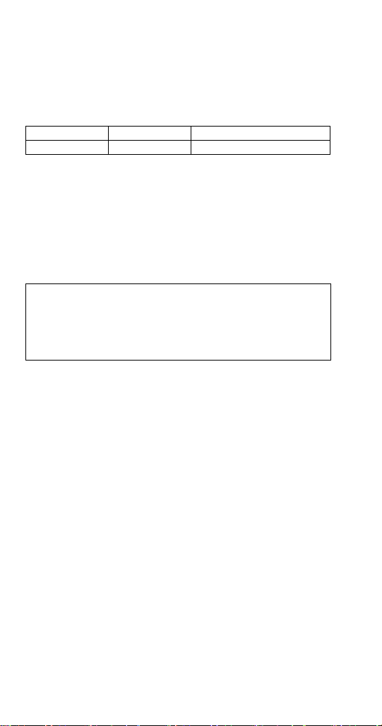
Step 6 Mix a solution of cleaner and lukewarm water.
Depending upon the amount of mineral buildup, a larger
quantity of solution may be required. Use the ratio in the
table below to mix enough solution to thoroughly clean all
parts.
Solution Type Water Mixed With
Cleaner 1 gal. (4 L) 16 oz (500 ml) cleaner
Step 7 Use 1/2 of the cleaner/water mixture to clean
all components. The cleaner solution will foam when it
contacts lime scale and mineral deposits; once the foaming
stops use a soft-bristle nylon brush, sponge or cloth (NOT
a wire brush) to carefully clean the parts. Soak parts for 5
minutes (15 - 20 minutes for heavily scaled parts). Rinse all
components with clean water.
Caution
,
Do not clean the ice thickness probe in a dishwasher.
Permanent damage to the ice thickness probe will
occur.
Ice Thickness Probe & Water Level Probe
Clean the probes using the following procedure.
NOTE: Do not soak electrical connectors in cleaner or
sanitizer solution.
1. Mix a solution of Manitowoc ice machine cleaner and
water (2 ounces of cleaner to 16 ounces of water) in
a container.
2. Clean all probe surfaces including all plastic parts
(do not use abrasives). Verify all surfaces are clean.
Thoroughly rinse probes with clean water.
3. Reinstall probe, then sanitize the ice machine and bin/
dispenser interior surfaces.
42 Part Number 000015430 Rev01 5/19
Page 45

Step 8 While components are soaking, use 1/2 of the
cleaner/water solution to clean all food zone surfaces of
the ice machine and bin (or dispenser). Use a nylon brush
or cloth to thoroughly clean the following ice machine
areas:
• Side walls
• Base (area above water trough)
• Evaporator plastic parts - including top, bottom, and
sides
• Bin or dispenser
Rinse all areas thoroughly with clean water.
SANITIZING PROCEDURE
Step 9 Mix a solution of sanitizer and lukewarm water.
Solution Type Water Mixed With
Sanitizer 3 gal. (12 L) 2 oz (60 ml) sanitizer
Step 10 Use 1/2 of the sanitizer/water solution to
sanitize all removed components. Use a spray bottle to
liberally apply the solution to all surfaces of the removed
parts or soak the removed parts in the sanitizer/water
solution. Do not rinse parts after sanitizing.
Step 11 Use 1/2 of the sanitizer/water solution to
sanitize all food zone surfaces of the ice machine and bin
(or dispenser). Use a spray bottle to liberally apply the
solution. When sanitizing, pay particular attention to the
following areas:
• Side walls
• Base (area above water trough)
• Evaporator plastic parts - including top, bottom and
sides
• Bin or dispenser
Do not rinse the sanitized areas.
Part Number 000015430 Rev01 5/19 43
Page 46

Step 12 Replace all removed components.
Step 13 Wait 20 minutes.
Step 14 Reapply power to the ice machine and press the
Clean button.
Step 15 Press the Clean button and select “Make ice
when complete”. Water will flow through the water dump
valve and down the drain. Wait approximately 1 minute
until the water trough refills and the display indicates Add
Chemical. Add the proper amount of ice machine sanitizer
to the water trough by pouring between the water curtain
and evaporator, then confirm the chemical was added.
Model Amount of Sanitizer
IF0300/IT0420/IT0450
IT0620/IT0450/IT0500/IF0600
IT0750/IF0900/IT0900
IT1200 3.5 ounces (104 ml)
IT1500/IT1900 6 ounces (180 ml)
3 ounces (90 ml)
Step 16 The ice machine will automatically start ice
making after the sanitize cycle is complete.
44 Part Number 000015430 Rev01 5/19
Page 47

Water Inlet Valve
The water inlet valve normally does not require removal
for cleaning. Refer to “Water System Checklist” page 115,
if you are troubleshooting water related problems.
1. When the ice machine is off, the water inlet valve
must completely stop water flow into the machine.
Watch for water flow.
When the ice machine is on, the water inlet valve must
allow the proper water flow through it. Press the On/
Off button to energize the ice machine. Watch for water
flow into the ice machine. If the water flow is slow or
only trickles into the ice machine, refer to water system
checklist.
NOTE: The valve can also be energized by navigating to
the service diagnostic menu, selecting control board, then
selecting “enable all relays”.
Warning
n
Disconnect the electric power to the ice machine and
dispenser at the electric service switch box and turn
off the water supply before proceeding.
Water Dump Valve
The water dump valve normally does not require removal
for cleaning. To determine if removal is necessary:
1. Locate the water dump valve.
2. While the ice machine is in the freeze mode, check
the drain to determine if the dump valve is leaking. If
there is no or little water in the water trough (during
the freeze cycle) the dump valve is leaking.
A. If the dump valve is leaking and debris is not
visible and easily removed, the dump valve must
be replaced.
B. If the dump valve is not leaking, do not remove
it. Instead, follow the “Ice Machine Cleaning
Procedure”.
Part Number 000015430 Rev01 5/19 45
Page 48

Preventative Maintenance Cleaning Procedure
This procedure cleans all components in the water flow
path, and is used to clean the ice machine between the
bi-yearly cleaning/sanitizing procedure.
Ice machine cleaner is used to remove lime scale and
mineral deposits. Ice machine sanitizer disinfects and
removes algae and slime.
NOTE: Although not required and dependent on your
installation, removing the ice machine top cover may allow
easier access.
1. Ice must not be on the evaporator during the clean/
sanitize cycle. Follow one of the methods below:
• Press the power switch at the end of a harvest cycle
after ice falls from the evaporator(s).
• Press the power switch and allow the ice to melt.
Caution
,
Never use anything to force ice from the evaporator.
Damage may result.
2. Open the front door to access the evaporator.
46 Part Number 000015430 Rev01 5/19
Page 49

3. Press the Clean button and select “Make ice when
complete”. Water will flow through the water dump
valve and down the drain. Wait approximately 1
minute until the water trough refills and the display
indicates Add Chemical. Add the proper amount of
ice machine cleaner to the water trough by pouring
between the water curtain and evaporator, then
confirm the chemical was added.
Model Amount of Cleaner
IF0300/IT0420/IT0620 3 ounces (90 ml)
IT0450/IT0500/IF0600/IT0750
IF0900/IT0900/IT1200
IT1500/IT1900 9 ounces (265 ml)
5 ounces (150 ml)
4. Close and secure the front door. The ice machine will
automatically start ice making after the clean cycle is
complete (approximately 24 minutes).
NOTE: Once the cycle has started it must complete before
the ice machine can make ice again. Returning it to ice
making mode will not cancel a clean cycle.
Part Number 000015430 Rev01 5/19 47
Page 50

Removal from Service/Winterization
General
Special precautions must be taken if the ice machine is to
be removed from service for an extended period of time or
exposed to ambient temperatures of 32°F (0°C) or below.
Caution
,
If water is allowed to remain in the ice machine
in freezing temperatures, severe damage to some
components could result. Damage of this nature is not
covered by the warranty.
Follow the applicable procedure below.
AIR-COOLED ICE MACHINES
1. Turn off the ice machine by pressing the On/Off
Button.
2. Turn off the water supply.
3. Remove the water from the water trough.
4. Disconnect and drain the incoming ice-making water
line at the rear of the ice machine.
5. Energize the ice machine and wait one minute for the
water inlet valve to open - or - Energize all relays in
the touchscreen service menu.
6. Blow compressed air in both the incoming water and
the drain openings in the rear of the ice machine until
no more water comes out of the water inlet lines or
the drain.
7. Disconnect the electric power at the circuit breaker or
the electric service switch.
8. Make sure water is not trapped in any of the water
lines, drain lines, distribution tubes, etc.
48 Part Number 000015430 Rev01 5/19
Page 51

WATER-COOLED ICE MACHINES
1. Perform steps 1-6 under “Self-Contained Air-Cooled
Ice Machines.”
2. Disconnect the incoming water and drain line from
the water-cooled condenser.
3. Start the ice making cycle by pressing the On/Off
button and wait for the freeze cycle. The increasing
refrigerant pressure will open the water regulating
valve.
4. Blow compressed air through the condenser until no
water remains.
5. Turn off ice machine by pressing the On/Off button
and then disconnecting power to the ice machine.
6. Perform a lock out tag out procedure.
Part Number 000015430 Rev01 5/19 49
Page 52

THIS PAGE INTENTIONALLY LEFT BLANK
50 Part Number 000015430 Rev01 5/19
Page 53
Operation
On/Off Button Touchscreen Lock Clean Button
11/18/2018 10:42 AM
3
MAKING
ICE
3
i
Touch Screen Features
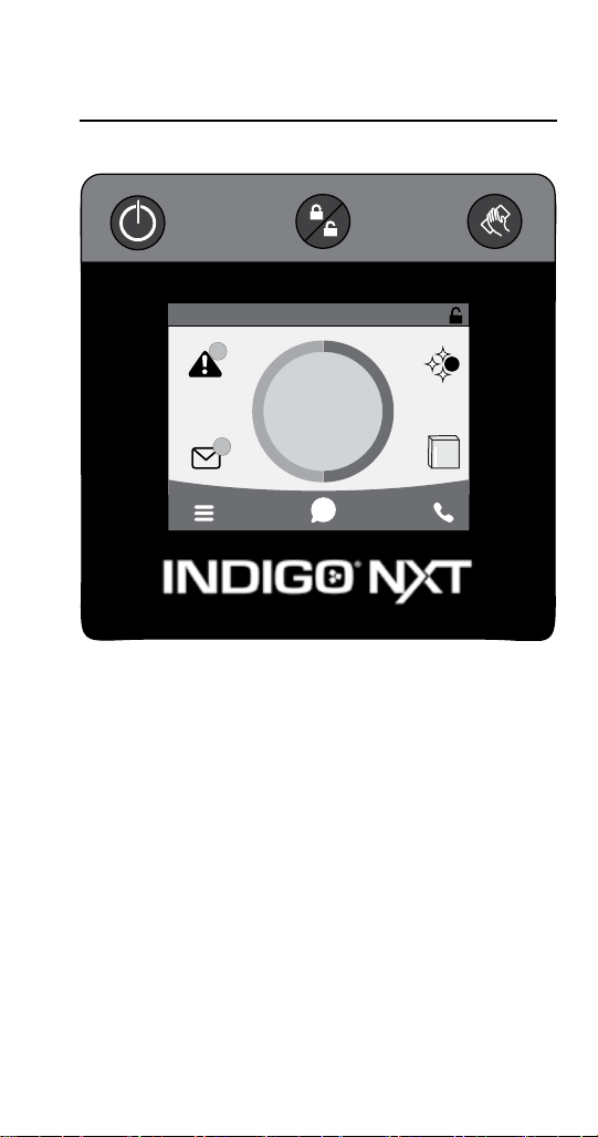
The Indigo® control panel offers a series of pressuresensitive buttons and an interactive touchscreen.
Buttons
On/Off Button: Provides On/Off functions for the ice
machine.
Lock/Unlock Button: Allows or prevents touchscreen
navigation.
Cleaning Button: Initiates a cleaning cycle. Refer to
“Cleaning and Sanitizing” on page 35 for details.
S
Part Number 000015430 Rev01 5/19
51
Page 54
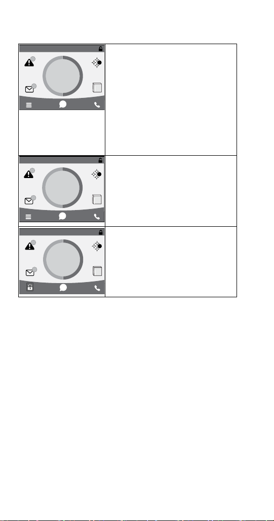
Touchscreen
11/18/2018 10:42 AM
11/18/2018 10:42 AM
3
MAKING
ICE
3
Home screen allows viewing of ice
machine status, alerts and messages.
S
Navigation with the touchscreen
provides access to menu items,machine
information, settings and event logs.
i
Setup and Energy Saver settings can be
adjusted along with access to service
and troubleshooting information. The
icons provide status indication and
allow navigation by pressing the icon.
11/18/2018 10:42 AM
3
Program
Mode On
3
i
3
MAKING
ICE
3
i
The touchscreen will display Program
Mode On, whenever the ice machine
S
is off due to a bin level probe, weight
program or time program.
The touchscreen will display a lock
in place of the menu icon when the
S
touchscreen has been locked.
52 Part Number 000015430 Rev01 5/19
Page 55
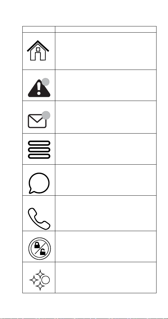
HOME SCREEN ICON DESCRIPTIONS
i
Icon Description
Home Screen Pressing this icon at any time will return the
display to the home screen.
State of ice Machine is the center portion of the
screen which displays the current condition of
the ice machine - Making ice, bin full, program
mode or machine off
Alert Alert icon with number of messages. Pressing
this icon will display the alert log which will
3
allow viewing and resetting of alerts
Message Message icon with umber of messages. Pressing
this icon will display the routine maintenance
3
reminder screen which will allow viewing and
resetting of the reminder
Menu Menu icon will take you to the main menu.
Note: This icon changes to a lock if the
touchscreen lock has been selected.
Information Information icon provides model and serial
number, installation date and other information
specific to the ice machine
Service
Locater
Lock/Unlock Indicates if screen is locked or unlocked.
LuminIce Only visible when a LuminIce II accessory is
Part Number 000015430 Rev01 5/19 53
Provides contact information for your local
service support - Default is the Manitowoc Ice
website service locater
The icon is only visible when the screen is
locked.
connected.
Blue S - Normal operation
S
Red S - Replace bulb
Red/Blue alternating - Incorrect bulb installed
Page 56
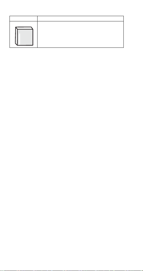
Icon Description
iAuCs This icon appears when the iAUCS activates
during a programed cleaning cycle.
54 Part Number 000015430 Rev01 5/19
Page 57
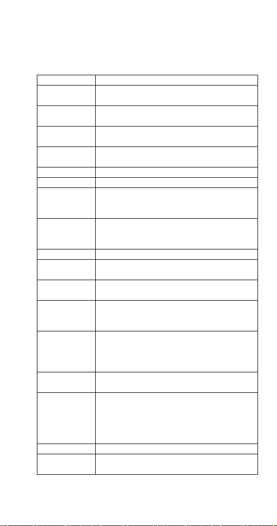
Setup Wizard
Screens will automacally advance aer a selecon is made or press the
arrows to advance/go back one screen. All sengs can be accessed and
changed without the wizard by using menu screen navigaon.
Setup Description
Press ON/OFF
Button
Select
Language
Start Wizard
Date and Time
Configuration
Set Local Time Use arrows to set local time.
Verify Date Use arrows to set date for your location.
Accessory
Detection
Optional
USB Settings
Download
Configure Units Select standard or metric.
Set Brightness
Optional Ice
Program
Optional
Cleaning
Reminder
Optional Clean
Air Filter
Air-cooled
models only
Optional Water
Filter Reminder
Water Usage
Option
Congratulations Setup wizard is complete
Turn On Ice
Machine
On/Off button is used to start/stop ice making.
Default is English. Scroll to select a different
language.
Setup wizard will guide ice machine
programming.
Select Month/Day/Year or Day/Month/Year.
Select 12 hour or 24 hour time format.
Detects if Ice Level Sensor, LuminIce II or AuCS
are connected.
Checkmark = yes - X = no
Only used when setup features have been
transferred to a USB drive. Skip screen by
selecting right arrow.
Configure screen brightness during normal
operation.
Program ice machine run times or press right
arrow to skip this setup.
Set clean and sanitize reminder or press right
arrow to skip.
Set to ON for self-contained air cooled models.
Select Yes or No.
Factory default - or - Use less water for reverse
osmosis systems (Refer to “Reverse Osmosis
or Deionized Water Usage” on page 148) or - Use more water to improve clarity for
unfiltered water
Turn on ice machine by pressing the On/Off
button.
Part Number 000015430 Rev01 5/19 55
Page 58
Menu Navigation Overview
SETTINGS MENU SCREEN NAVIGATION
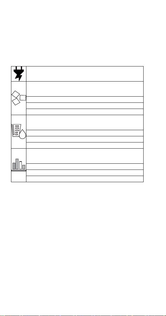
Select SETTINGS Icon from the Home Screen to access
Main Menu screen. The main menu screen contains four
main headings, which allow access to subheadings under
each main heading.
Energy
Ice Program
Continuous Mode - Default, No Program
Time Program - Select Daily On/Off times
Weight Program - Select Daily Production Weight
Water Usage
Use Factory Default
Use Less Water With Reverse Osmosis
Use More Water To Improve Ice Clarity
Statistics
Ice Production - Previous 7 Days
Water Usage - Previous 7 Days
Energy Usage - Previous 7 Days
NOTE: The performance statistics are calculated based on
the performance of the ice machine at 900F (320C) ambient
temperature and 700F (210C) water temperature. The
actual statistics will vary dependent on your environmental
conditions.
56 Part Number 000015430 Rev01 5/19
Page 59
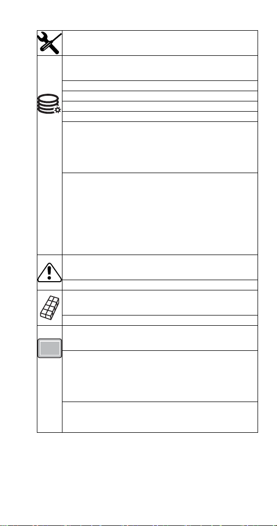
Service
Data
Real Time Data
Time and Temperature
Inputs
Outputs
Data History for 5 Previous Days
Minimum and Maximum Freeze (Length, Time of day,
Thermistor Temperatures)
Minimum and Maximum Harvest (Length, Time of day,
Thermistor Temperatures)
Lifetime Data History
Installation Date
Control Board Replacement Date
Control Board Manufacture Date
Runtime
Cycle Count
Potable Water
Clean Cycles
Alert Log
Lists/Clears Alerts
Manual Harvest
Off or On
Control Board Replacement
Manual Replacement
Manually enter model number
Manually enter serial number
Manually enter condenser serial number (optional)
Verification
USB Replacement
Import to ice machine
Export to USB
Part Number 000015430 Rev01 5/19 57
Page 60
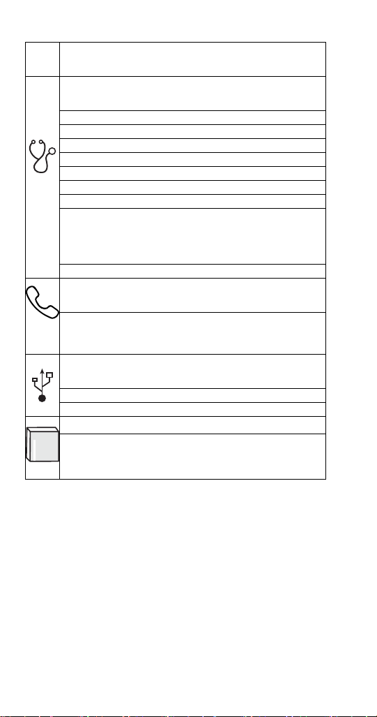
Service
Diagnostics
Control board
Enable All Relays
Self Check
Temperature Sensors
Lists Sensor Temperatures
Inputs
Lists Control Board Input Information
User Interface
Screen Calibration
Button Diagnostics
Screen Diagnostics
Screen Calibration
Contact information
Factory defaults to QR code and website address to
Manitowoc Ice’s Global Locator.
Edit Contact Information Button.
USB
Upgrade Firmware
Export Data
iAuCS
Manually initiate the iAuCS pump for pump/hose
priming. NOTE The clean button does not initiate the
iAuCS pump.
58 Part Number 000015430 Rev01 5/19
Page 61
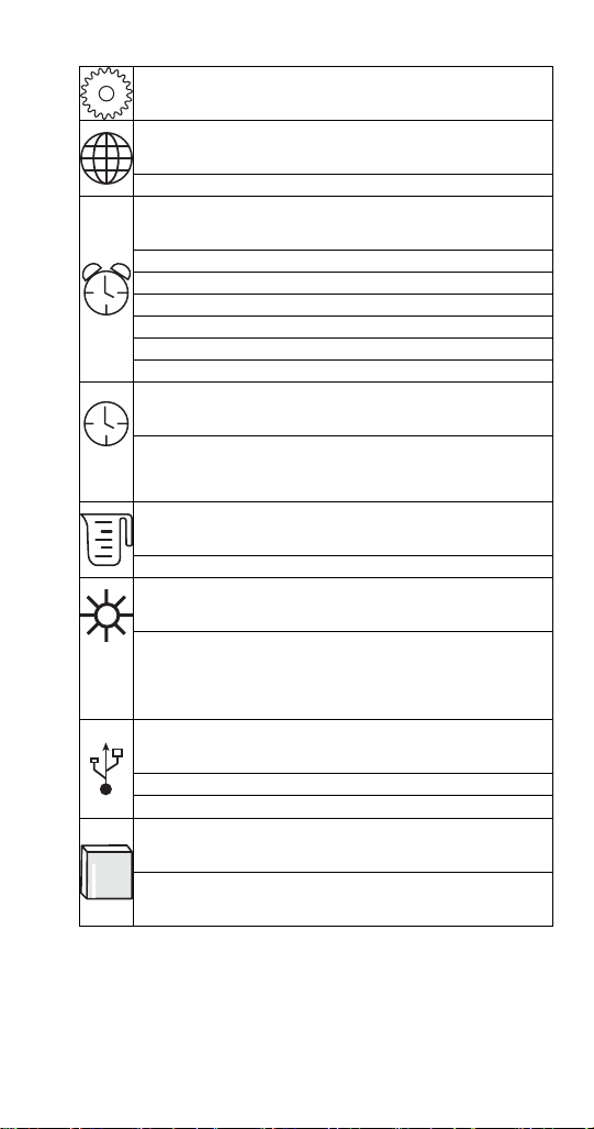
Settings
Language
Select Language
Reminders
Clean Reminder
Set Month Interval
Air Filter
Set On/Off/Interval
Water Filter
Set Reminder
Configure Date & Time
Configure Date & Time
Set Time
Set Date
Units
Standard or Metric
Brightness
Adjust Touch Screen Brightness For Sleep Mode or
Inactivity.
NOTE: 100% brightness is activated by touching the
screen when the lock feature is off.
USB
Import Settings To Ice Machine
Export Settings To USB
IAuCs
When the iAuCS is detected, the icon will appear in the
settings menu to set frequency of cleanings with iAuCS
Part Number 000015430 Rev01 5/19 59
Page 62
Reset Defaults
Require Setup Wizard
Optional Setup Wizard restart for training purposes
or resale of equipment.
Backup Current Settings
Import To Ice Machine
Export To USB
Reset Factory Defaults
60 Part Number 000015430 Rev01 5/19
Page 63

Operational Checks
GENERAL
Manitowoc ice machines are factory-operated and
adjusted before shipment. Normally, new installations do
not require any adjustment.
To ensure proper operation, always follow the Operational
Checks:
• when starting the ice machine for the first time
• after a prolonged out of service period
• after cleaning and sanitizing
NOTE: Routine adjustments and maintenance procedures
are not covered by the warranty.
Important
Refrigeration compressors must be operated for a
minimum break in period of 24 hours before full ice
production will be reached.
Part Number 000015430 Rev01 5/19 61
Page 64
ICE THICKNESS CHECK
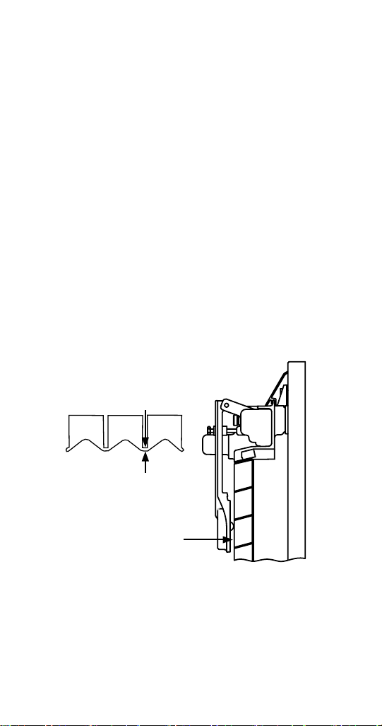
The ice thickness probe is factory-set to maintain the ice
bridge thickness at 1/8 in. (3 mm).
NOTE: Make sure the water curtain/splash shields are in
place when performing this check. It prevents water from
splashing out of the water trough. Remove the curtain to
make an adjustment, then replace immediately after the
adjustment is made.
1. Inspect the bridge connecting the cubes. It should be
1/8 in. (3 mm) thick.
2. If adjustment is necessary, turn the ice thickness
probe adjustment screw clockwise to increase bridge
thickness or counterclockwise to decrease bridge
thickness. Set a 9/32” gap between the ice thickness
probe and evaporator as a starting point. Then adjust
to achieve 1/8” ice thickness.
3. Make sure the ice thickness probe wire and the
bracket do not restrict movement of the probe.
1/8" (3 mm)
ICE BRIDGE THICKNESS
PLACE 9/32" (7MM) DRILL BIT
HERE TO SET INITIAL GAP
Ice Thickness Check
NOTE: Turning the adjustment 1/3 of a turn will change the
ice thickness about 1/16” (1.5 mm). Make adjustment only
when the ice machine is off to prevent initiating a harvest.
62 Part Number 000015430 Rev01 5/19
Page 65

Control Board Timers
The control board has the following non-adjustable timers:
• The ice machine is locked into the freeze cycle for 6
minutes before the ice thickness probe can initiate a
harvest cycle.
• The maximum freeze time is 35 minutes at which time
the control board automatically initiates a harvest
sequence.
• The maximum harvest time is 7 minutes, the control
board will preform a Thaw Cycle and then return the
ice machine to the freeze cycle.
• Maximum water fill time in the freeze cycle:
• Single evaporator 6 minutes.
• Dual evaporator 8 minutes.
Part Number 000015430 Rev01 5/19 63
Page 66

Sequence of Operation
SELF CONTAINED AIR OR WATER COOLED
NOTE: The On/Off button must be depressed and the
water curtain/ice dampers must be in place on the
evaporator before the ice machine will start.
Initial Start-Up or Start-Up After
Automatic Shut-Off
1. Water Purge
Before the compressor starts, the water pump and water
dump solenoid energize to purge the ice machine of old
water. This feature ensures that the ice making cycle starts
with fresh water.
2. Refrigeration System Equalization and Start-Up
The harvest valve(s) and air pump(s) energize to equalize
high and low side refrigeration pressure.
After 5 seconds the contactor energizes the compressor
and supplies power to the condenser fan motor. After 5
seconds the harvest valve(s) and air pump(s) de-energize.
NOTE: The fan motor is wired through a fan cycle pressure
control. When the discharge pressure exceeds the cut in
pressure the fan cycle switch closes and energizes the fan
motor.
Freeze Sequence
3. Prechill
The compressor is on for 30 seconds (120 seconds initial
cycle) to lower the temperature of the evaporator(s)
before the water pump is energized. The water fill valve
will energize and remain on until water touches the low
and high, water level probes for 5 seconds.
64 Part Number 000015430 Rev01 5/19
Page 67

4. Freeze
Water Pump
The water pump(s) energizes and water flows over the
evaporator. The water pump is energized throughout the
freeze cycle.
Water Inlet Valve
The water inlet valve energized in prechill. After water
contacts the low and high water probes the water fill valve
de-energizes. Ice builds on the evaporator and the water
level drops. When water loses contact with the high water
probe, the water fill valve energizes until water contacts
the high water probe again.
Maximum Fill Time = Prechill fill time + first fill + second fill.
SINGLE EVAPORATOR MAXIMUM FILL TIME
Initial startup or startup after automatic shutoff
Prechill (2 minutes) + first fill time (6 minutes) + second fill
time (6 minutes) = 14.0 minutes.
Consecutive cycles
Prechill (30 sec.) + first fill time (6 minutes) + second fill
time (6 minutes) = 12.5 minutes.
DUAL EVAPORATOR MAXIMUM FILL TIMES
Initial startup or startup after automatic shutoff
Prechill (2 minutes) + first fill time (8 minutes) + second fill
time (8 minutes) = 18.0 minutes.
Consecutive cycles
Prechill (30 sec.) + first fill time (8 minutes) + second fill
time (8 minutes) = 16.5 minutes.
Part Number 000015430 Rev01 5/19 65
Page 68

Ice Thickness Probe
The freeze cycle continues until the six minute freeze lock
expires and enough ice has formed to send a signal from
the ice thickness probe to the control board.
During the first 6 minutes of the freeze cycle the ice
thickness probe microphone samples ambient noise.
6 minutes into the freeze cycle baseline readings are
recorded. Ice formation on the evaporator will change
the readings; when the baseline readings are exceeded a
harvest cycle starts.
Harvest Sequence
5. Water Purge
The air pump(s) (when used) and the harvest valve(s) open
at the beginning of the water purge to divert discharge
refrigerant gas into the evaporator.
The water pump(s) continues to run, and the water dump
valve energizes to purge any remain water in the water
trough down the drain.
66 Part Number 000015430 Rev01 5/19
Page 69

6. Harvest
The air pump (when used) remains energized and the
harvest valve(s) remains open. The refrigerant gas warms
the evaporator causing the cubes to slide, as a sheet, off
the evaporator and into the storage bin. If the damper/
curtain does not open within 3.5 minutes in the harvest
cycle the following occurs:
• 3.5 minutes - The water inlet valve energizes until
water touches the high water level probe.
• 4 minutes - The water pump energizes.
• 6.5 to 7 minutes - The water dump valve energizes.
When the sliding sheet of cubes opens and closes within
30 seconds the bin switch terminates the harvest sequence
and returns the ice machine to the freeze sequence (Step
3 - 4.)
NOTE: If bin switch does not open before 7 minutes the ice
machine will start a Thaw Cycle - Refer to “Thaw Cycle” on
page 92. for details.
Automatic Shut-Off
7. Automatic Shut-Off
When the storage bin is full at the end of a harvest
sequence, the sheet of cubes fails to clear the water
curtain/ice damper and will hold it open. After the water
curtain/ice damper is held open for 30 seconds, the ice
machine shuts off. The ice machine remains off for 3
minutes before it can automatically restart.
The ice machine remains off until enough ice has been
removed from the storage bin to allow the ice to fall clear
of the water curtain or all of the ice dampers. As the water
curtain/ice dampers swing back to the closed position, the
bin switch re-closes and the ice machine restarts (steps 1 -
2), provided the 3 minute delay period is complete.
Part Number 000015430 Rev01 5/19 67
Page 70
Length of Time
45 Seconds
5 Seconds
Initial Start-Up
is 120 Seconds
30 Seconds
thereafter
Until Ice
Contact w/
Probe
45 Seconds
Ice Thickness
Factory Set at
Activation
Bin Switch
Fan Motor
Compressor Condenser
Coil
Contactor
Valve
Dump
Water
Valve
Water Inlet
Air
Pump(s)*
Harvest
Valve(s)
Pump
Water
On/Off
May Cycle
Off On On
On/Off
May Cycle
On Off Off Off On Off Off Off
Off On On Off Off Off Off Off
Off Off Off
May Cycle
Cycle On/
Off On On
On Off Off
On/Off
On/Off
On/Off
May Cycle
May Cycle
Off
On On On Off Off On On
Off On On Off Off On On
of Operation
Ice Making Sequence
ENERGIZED PARTS CHART SELF CONTAINED AIR OR WATER-COOLED MODELS
68 Part Number 000015430 Rev01 5/19
1. Water Purge
2. Pressure Equalization
Initial Start-Up
B. Compressor Startup Off On On Off Off On On Off 5 Seconds
Freeze Sequence
3. Prechill
4. Freeze
5. Water Purge
6. Harvest
Harvest Sequence
Page 71

Length of Time
Until Water
Contact w/
Water Level
Probe
Bin Switch
Activation or 7
minutes
Bin Switch
minutes
**Until 3
Activation or 7
Minute Delay
closes
Expires and
Bin Switch Re-
Fan Motor
Compressor Condenser
Coil
Contactor
Valve
Dump
Water
Valve
Water Inlet
Air
Pump(s)*
Harvest
Valve(s)
Pump
Water
May Cycle
Off On On On Off On On
May Cycle
On/Off
On/Off
On On On Off Off On On
May Cycle
On On On Off Off On On
On/Off
Off Off Off Off Off Off Off Off
of Operation
Ice Making Sequence
Thaw Cycle
Start s 3.5 minutes in harvest
cycle
Thaw Cycle
Thaw Cycle
Start s 4 minutes in har vest
cycle
7. Automatic Shut-
cycle
Off
* Not used on all models
** A thaw will start when the bin switch does not open within 7 minutes of the start of a harvest cycle.
Dump valve energizes at
6.5 minutes in harvest
Part Number 000015430 Rev01 5/19 69
Page 72

REMOTE CONDENSER
NOTE: The On/Off button must be depressed and the
water curtain/ice dampers must be in place on the
evaporator before the ice machine will start.
Initial Start-Up or Start-Up After
Automatic Shut-Off
1. Water Purge
Before the compressor starts, the water pump and water
dump solenoid are energized for 45 seconds, to completely
purge the ice machine of old water. This feature ensures
that the ice making cycle starts with fresh water.
2. Refrigeration System Equalization and Start-Up
The harvest valve, air pump(s) and harvest pressure
regulating (HPR) solenoid valves energize to equalize high
and low side refrigeration pressure.
After 5 seconds the liquid line solenoid valve energizes and
the contactor energizes the compressor and condenser fan
motor.
Freeze Sequence
3. Prechill
The compressor is on for 30 seconds (120 seconds initial
cycle) to lower the temperature of the evaporator(s)
before the water pump is energized. The water fill valve
will energize and remain on until water touches the low
and high water level probes.
70 Part Number 000015430 Rev01 5/19
Page 73

Freeze
Water Pump
The water pump(s) energizes and water flows over the
evaporator. The water pump is energized throughout the
freeze cycle.
Water Inlet Valve
Water Inlet Valve
The water inlet valve energized in prechill. After water
contacts the low and high water probes the water fill valve
de-energizes. Ice builds on the evaporator and the water
level drops. When water loses contact with the high water
probe, the water fill valve energizes until water contacts
the high water probe again.
Maximum Fill Time = Prechill fill time + first fill + second fill.
SINGLE EVAPORATOR MAXIMUM FILL TIME
Initial startup or startup after automatic shutoff
Prechill (2 minutes) + first fill time (6 minutes) + second fill
time (6 minutes) = 14.0 minutes.
Consecutive cycles
Prechill (30 sec.) + first fill time (6 minutes) + second fill
time (6 minutes) = 12.5 minutes.
DUAL EVAPORATOR MAXIMUM FILL TIMES
Initial startup or startup after automatic shutoff
Prechill (2 minutes) + first fill time (8 minutes) + second fill
time (8 minutes) = 18.0 minutes.
Consecutive cycles
Prechill (30 sec.) + first fill time (8 minutes) + second fill
time (8 minutes) = 16.5 minutes.
Part Number 000015430 Rev01 5/19 71
Page 74

Ice Thickness Probe
The freeze cycle continues until the six minute freeze lock
expires and enough ice has formed to send a signal from
the ice thickness probe to the control board.
During the first 6 minutes of the freeze cycle the ice
thickness probe microphone samples ambient noise.
6 minutes into the freeze cycle 4 baseline readings are
recorded. Ice formation on the evaporator will change
the readings; when two of the four baseline readings are
exceeded a harvest cycle starts.
Harvest Sequence
4. Water Purge
The air pump (when used) the harvest valve(s) and
harvest pressure regulating valve (HPR) energize to divert
refrigerant gas to the evaporator.
The water pump continues to run, and the water dump
valve energizes to purge the water in the water trough.
5. Harvest
The harvest valve, air pump(s) and harvest pressure
regulating (HPR) solenoid valves remain energized and the
refrigerant gas warms the evaporator causing the cubes to
slide, as a sheet, off the evaporator and into the storage
bin. If the damper/curtain does not open within 3.5
minutes in the harvest cycle the following occurs:
• 3.5 minutes - The water inlet valve energizes until
water touches the high water level probe.
• 4 minutes - The water pump energizes.
• 6.5 to 7 minutes - The water dump valve energizes.
When the sliding sheet of cubes opens and closes within
30 seconds the bin switch terminates the harvest sequence
and returns the ice machine to the freeze sequence (Step
3 - 4.)
NOTE: If bin switch does not open before 7 minutes the ice
machine will start a Thaw Cycle - Refer to “Thaw Cycle” on
page 92. for details.
72 Part Number 000015430 Rev01 5/19
Page 75

Automatic Shut-Off
6. Automatic Shut-Off
When the storage bin is full at the end of a harvest
sequence, the sheet of cubes fails to clear the water
curtain/ice damper and will hold it open. After the water
curtain/ice damper is held open for 30 seconds, the ice
machine shuts off. The ice machine remains off for 3
minutes before it can automatically restart.
The ice machine remains off until enough ice has been
removed from the storage bin to allow the ice to fall clear
of the water curtain or all of the ice dampers. As the water
curtain/ice dampers swing back to the closed position, the
bin switch re-closes and the ice machine restarts (steps 1 -
2), provided the 3 minute delay period is complete
Part Number 000015430 Rev01 5/19 73
Page 76
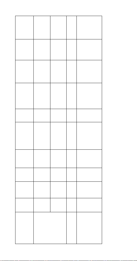
Time
Length of
Fan Motor
Condenser
Compressor
Solenoid
Liquid Line
Contactor Coil
Up is 120
Initial Start-
Seconds
30 Seconds
thereafter
Startup
May Cycle On/
Freeze
Sequence
Off On On On
prechill
Off during
Off Off Off Off
3. Prechill
Valve
Dump
Water
Valve
Water Inlet
Air
Pump(s)*
HPR
Valve
Harvest
Valve(s)
On Off Off Off Off On Off Off Off 45 Seconds
Pump
Water
Operation
Ice Making
Sequence of
ENERGIZED PARTS CHART REMOTE AIR-COOLED CONDENSER MODELS
74 Part Number 000015430 Rev01 5/19
Initial Start-Up
Off On On On Off Off Off Off Off 5 Seconds
Off On Off On Off Off On On On 5 Seconds
Equalization
1. Water Purge
2. Pressure
B. Compressor
Page 77
Time
Length of
Fan Motor
Condenser
Compressor
Solenoid
Liquid Line
Contactor Coil
Valve
Dump
Water
Valve
Water Inlet
Air
Pump(s)*
HPR
Valve
Until Ice
Contact w/
Cycles Off
Probe
Ice Thickness
Off On On On
more time
then On one
Factory
Seconds
Set at 45
Activation
Bin Switch
Until Water
Contact w/
Water Level
Probe
Harvest
Valve(s)
Pump
Water
Operation
Ice Making
Sequence of
On On On On Off On On On On
4. Freeze On Off Off Off
Harvest
Off On On On Off Off On On On
5. Water Purge
6. Harvest
Sequence
Thaw Cycle
Off On On On On Off On On On
Start s 3.5 minutes
in harvest cycle
Part Number 000015430 Rev01 5/19 75
Page 78
Time
Length of
Fan Motor
Condenser
Compressor
Solenoid
Liquid Line
Contactor Coil
Valve
Dump
Water
Valve
Water Inlet
Air
Pump(s)*
HPR
Valve
7 minutes
Bin Switch
Activation or
7 minutes
Bin Switch
Activation or
**Until
3 Minute
Delay
Re-closes
Bin Switch
Expires and
Harvest
Valve(s)
Pump
Water
Operation
Ice Making
Sequence of
Thaw Cycle
On On On On Off Off On On On
Water pump
energizes at 4
minutes in harvest
On On On On Off On On On On
Off Off Off Off Off Off Off Off Off
Shut-Off
Thaw Cycle
cycle
Dump valve
energizes at 6.5
minutes in harvest
7. Automatic
cycle
* Not used on all models
** A Thaw Cycle will start when the bin switch does not open within 7 minutes of the start of a harvest cycle.
76 Part Number 000015430 Rev01 5/19
Page 79

Troubleshooting
Troubleshooting
Check the touchscreen for alerts - An alert icon with the
number of messages will be displayed if alerts are present.
Pressing the alert icon will display the alert log which will
allow viewing and resetting of alerts. Refer to the alert log
and event log on the following pages for a description of
the event.
NOTE: There are two sequences that allow the ice machine
to continue ice making during alert events:
Thaw Cycle
When the damper/curtain does not open during the 7
minute harvest cycle (E02 fault) a thaw cycle starts.
See ”Thaw Cycle” on page 92
Safe Operation Mode
Allows the ice machine to operate up to 72 hours if the
ice thickness probe (E19 fault) and/or water level probe
sensors fail (E20 fault).
See “Safe Operation Mode” on page 93
Part Number 000015430 Rev01 5/19 85
Page 80
EVENT LOG
Refer to Event Log Detail For Code descriptions.
Displayed Text Code Description
Long Freeze E01 Long Freeze Cycle
Long Harvest E02 Long Harvest Cycle
Power Loss E03 Input Power Loss
Hi cnd Temp or
Wtr Cnd Fault
HPC Fault E05 High Pressure Control Opened
Starving TXV E07 Starving TXV Single Evaporator or Low On
TXV Fault E08 TXV Fault Single or Dual Circuit
Flood Evap1 E09 Flooding Evaporator Fault Single
Flood Evap2 E10 Flooding Evaporator Fault Dual TXV, Dual
Refrig Fault E11 Refrigeration Fault
Curtain Fault E12 Curtain Switch Fault - Open more than
Low liq temp E15 Fan Cycle Control Fault - Low Liquid Line
Rmt Cnd Fault E16 Remote Condensing Unit Fault (CVD Only)
ITP Fault E19 Ice Thickness Probe Fault
WTR Fault E20 Water System Fault
T1 Fault E21 T1 Temperature Sensor Issue
T2 Fault E22 T2 Temperature Sensor Issue
T3 Fault E23 T3 Temperature Sensor Issue
T4 Fault E24 T4 Temperature Sensor Issue
Bin Probe Fault E25 Bin Level Probe Low Sensor Fault
AUCS E26 T6 or T7 Temperature Sensor Issue
USB COMM E27 T6 or T7 Temperature Sensor Issue
USB DNLD E28 iAuCS
Safe Mode E31 Safe Mode
RS485 COMM E32 RS485 Communication Fault
Keyboard E33 Touchscreen Fault
Display E34 Display Fault
E04 High Condenser Temperature
E06 Spare
Charge
Evaporators
Evaporator, Single Circuit
Circuit
24 hours
E13 Spare
E14 Spare
Temperature
E17 Spare
E18 Spare
E29 USB Communication Fault
E30 USB Download Fault
86 Part Number 000015430 Rev01 5/19
Page 81

Displayed Text Code Description
Checksum E36 Check Sum Error
WatchDog E37 Watch Dog Event
UI Comm E38 UI Comm Event
EVENT LOG DETAIL
E01 Long Freeze
3 consecutive 35 minute freeze cycles = Ice machine is off.
E02 Long Harvest
3 consecutive 7minute harvest cycles = Ice machine is off.
E03 Power Loss
When power is interrupted to the ice machine the control
board will log the event in the ELOG and stamp the loss of
power on power-up.
E04 High Condenser Temperature
Liquid Line Temperature too High for Self-contained Air
Cooled Ice machine = Air Cooled Condenser Fault
Or
Liquid Line Temperature too High for Self-contained Water
Cooled ice machine = Water Cooled Condenser Fault
E05 High Pressure Control Opened
The high pressure cutout switch (HPCO) opened.
E06 Spare
E07 Starving TXV Single Evaporator or Low On Charge
The difference of the average evaporator inlet (T3) and
outlet (T4) is greater than 12°F in the last 1 minute of the
freeze cycle.
E08 TXV Fault Single or Dual Circuit Evaporators
The difference of the average evaporator inlet (T3) and
outlet (T4) is greater than 12°F in the last 1 minute of the
freeze cycle.
Part Number 000015430 Rev01 5/19 87
Page 82

E09 Flooding Evaporator Fault Single Evaporator, Single
Circuit
Average compressor discharge line temperature during
the first 6 minutes of the freeze cycle (T2) compared to the
average of the Prechill (T1) +50°F is less than 1.05°F.
E10 Flooding Evaporator Fault Dual TXV, Dual Circuit
Average compressor discharge line temperature during
the first 6 minutes of the freeze cycle (T2) compared to the
average of the Prechill (T1) +50°F is less than 1.05°F.
E11 Refrigeration Fault
The compressor discharge temperature did not increase
by at least 10° F, and the evaporator temperature did not
decreased by at least 10° F - Measured from Refrigeration
Start up or Prechill until 2 minutes into the Freeze cycle.
E12 Curtain Switch Fault Open more than 24 hours
The ice machine is set to ice making and remains in bin
full condition for more than 24 hours. The curtain switch is
open or curtain is off.
E13 Spare
E14 Spare
E15 Fan Cycle Control Fault - Low Liquid Line Temperature
The liquid line temperature dropped below 60° F for more
than one continuous minute during the freeze cycle.
E16 Remote Condensing Unit Fault (CVD Only)
The liquid line temperature dropped below 40° F, or
exceeded 140° F for more than 1 continuous minute during
the freeze cycle.
E17 Spare
E18 Spare
88 Part Number 000015430 Rev01 5/19
Page 83

E19 Ice Thickness Probe Fault
The monitored Frequencies is out of the appropriate range
(Probe unplugged or problem with microphone).
E20 Water System Fault
Any of the following:
1. Sensing high water probe and not low water probe.
2. Evaporator outlet temperature is less than -10°F 6.5
to 7.5 minutes in freeze cycle.
3. Low water probe is satisfied at the end of harvest.
4. Low or high water probe is satisfied at end of freeze
cycle.
E21 T1 Temperature Sensor Issue
During Pre-chill the thermistor had an average value
reading outside the valid range.
E22 T2 Temperature Sensor Issue
During Pre-chill the thermistor had an average value
reading outside the valid range.
E23 T3 Temperature Sensor Issue
During Pre-chill the thermistor had an average value
reading outside the valid range.
E24 T4 Temperature Sensor Issue
During Pre-chill the thermistor had an average value
reading outside the valid range.
E25 Bin Level Probe Low Sensor Fault
The thermistor had an average value reading outside of
the valid range for 10 continuous minutes.
Part Number 000015430 Rev01 5/19
89
Page 84

E26 T6 or T7 Temperature Issue
The thermistor had an average value reading outside of
the valid range.
E27 T6 or T7 Temperature Issue
The thermistor had an average value reading outside of
the valid range.
E28 AuCS
When the AUCS clean option is selected from the menu,
the control checks for the presence of the AUCS board.
When the AUCS is not connected it will signal an Event
which will clear as soon as the hardware is detected.
E29 USB Communication Fault
USB Communication error; No USB drive in port or
defective USB drive.
E30 USB Download Fault
USB Download error related to USB drive or a defective
USB drive.
E31 Safe Mode
Safe mode allows the ice machine to operate for a period
of time in the event of a Water level or ice thickness probe
failure. The controller allows the machine to operate based
on model data and historical cycle information.
E32 RS485 Communication Fault
The device plugged into the RS485 port is not
communicating between the control board and gateway.
E33 Touchscreen Fault
The Touchscreen is not plugged into the control board or
is faulty.
E34 Display Fault
The touchscreen is not plugged into the control board or
is faulty.
90 Part Number 000015430 Rev01 5/19
Page 85

E36 Check Sum Error
Event Log Only: Activates on power loss.
E37 Watch Dog Event
Event Log Only: Micro Process time out, possible electrical
noise.
E38 UI Comm Event
Event Log Only: User interface communication error: loose
communication cable, power interruption.
Part Number 000015430 Rev01 5/19 91
Page 86

THAW CYCLE
When the damper/curtain does not open during the 7
minute harvest cycle the following Thaw Cycle occurs:
• 7 minutes - The compressor, harvest solenoid valve
and dump valve de-energize.
The water pump remains energized and the water inlet
valve energizes until water touches the high water
level probe.
• Water is circulated, dumped and refilled to the high
water level probe 18 times (approximately 1 hour).
Model 1200 or smaller:
Circulate 165 seconds, dump 45 seconds
Model 1400 and larger
Circulate 240 seconds, dump 120 seconds
• At the end of the thaw cycle (approximately 1 - 1.75
hour) the ice machine will start another freeze cycle.
Curtain Operation In Thaw Cycle Harvest
• Open & close damper = Continue Thaw Cycle
• Open damper 30 seconds = Full Bin Shutoff
Use the keypad and turn the ice machine off and then on
to terminate the cycle. Disconnecting and reconnecting
power to end the cycle will result in the ice machine
restarting in a harvest cycle.
92 Part Number 000015430 Rev01 5/19
Page 87

SAFE OPERATION MODE
Allows the ice machine to operate up to 72 hours if the
ice thickness probe (E19 fault) and/or water level probe
sensors fail (E20 fault).
• When the control board starts the safe mode an
alert is indicated to notify the end-user they have a
production problem.
• The control board automatically initiates and monitors
the safe mode. The control will automatically exit the
safe mode if a normal signal is received from the input.
• After 72 hours the control board will enter a standby
mode and turn off.
• The control board needs a five cycle history to operate
safe mode. If five cycles have never been successfully
completed the ice machine will shut-off.
Part Number 000015430 Rev01 5/19 93
Page 88

E01 LONG FREEZE CYCLE
If the freeze time reaches 35 minutes, the control board
automatically initiates a harvest cycle. If 3 consecutive
35-minute freeze cycles occur, the ice machine stops.
E02 LONG HARVEST CYCLE
If the harvest time reaches 7 minutes, the control board
will start a Thaw Cycle and automatically return the ice
machine to the freeze cycle. After 3 consecutive long
harvest cycles the ice machine stops.
STOPPED THE ICE MACHINE
Service Faults are designed to stop the ice machine prior
to major component failures, most often a minor problem
or something external to the ice machine. This may be
difficult to diagnose, as many external problems occur
intermittently.
Example: An ice machine stops intermittently on Service
Fault (long freeze times). The problem could be a low
ambient temperature at night, a water pressure drop, the
water is turned off one night a week, etc.
Refrigeration and electrical component failures will cause
a Service Fault trip. Eliminate all electrical components
and external causes first. If it appears that the refrigeration
system is causing the problem, use Manitowoc’s Freeze
Cycle Refrigeration System Operational Analysis Table,
along with detailed charts, checklists, and other references
to determine the cause.
The following checklists are designed to assist the service
technician in analysis. However, because there are many
possible external problems, do not limit your diagnosis to
only the items listed.
94 Part Number 000015430 Rev01 5/19
Page 89

E01 LONG FREEZE
Freeze time exceeds 35 minutes for 3 consecutive freeze
cycles.
Possible cause checklist
Improper Installation
• Refer to “Installation/Visual Inspection Checklist” on
page 114
Water System
• Dirty/defective water level probe
• Low water pressure (20 psig min.)
• High water pressure (80 psig max.)
• High water temperature (90°F/32.2°C max.)
• Clogged water distribution tube
• Dirty/defective water fill valve
• Dirty/defective water dump valve
• Defective water pump
• Loss of water from sump area
Electrical System
• Low incoming voltage
• Ice thickness probe out of adjustment
• Harvest cycle not initiated electrically
• Contactor not energizing
• Compressor electrically non-operational
• Defective fan cycling control
• Defective fan motor
Miscellaneous
• Non-Manitowoc components
• Improper refrigerant charge
• Defective head pressure control
• Defective harvest valve
• Defective compressor
• TXV starving or flooding (check bulb mounting)
• Non-condensible in refrigeration system
• Plugged or restricted high side refrigerant lines or
component
• Restricted air flow/dirty condenser fins
• High inlet air temperature
• Condenser discharge air recirculation
Part Number 000015430 Rev01 5/19 95
Page 90

E02 LONG HARVEST
Harvest time exceeds 7 minutes for 3 consecutive harvest
cycles.
Possible Cause Checklist
Improper Installation
• Refer to ”Installation/Visual Inspection Checklist” on
page 114
Water System
• Water area (evaporator) dirty
• Dirty/defective water dump valve
• Vent tube not installed on water outlet drain
• Water freezing behind evaporator
• Plastic extrusions and gaskets not securely mounted to
the evaporator
• Clogged water distribution tube
Electrical System
• Ice thickness probe out of adjustment
• Bin switch closed/defective
• Premature harvest - The control board initiates a
harvest cycle when the high water level probe circuit is
complete and the low water level probe is open.
Refrigeration System
• Non-Manitowoc components
• Improper refrigerant charge
• Defective head pressure control valve
• Defective harvest valve
• TXV flooding (check bulb mounting)
• Defective fan cycling control
• Water cooled only - Water regulating valve is
incorrectly adjusted or will not close during harvest
cycle.
96 Part Number 000015430 Rev01 5/19
Page 91

Troubleshooting By Symptom
The troubleshooting procedures follow diagnostic charts.
There are four symptoms, the symptom that you are
experiencing will determine which diagnostic chart to
use. The chart asks yes and no questions to determine
the problem. The diagnostic chart will direct you to a
procedure to correct the problem. Remote condenser, and
self contained models use separate charts.
SYMPTOM #1
Ice Machine Stops Running
Ice machine is in Ice Making cycle
or
Has a History of Shutting Down
• Refer to Ice Machine Stops Running diagnostic chart
SYMPTOM #2
Ice Machine has a Long Freeze Cycle.
Ice Formation is Thick
or
Thin Ice Fill on Inlet or Outlet of Evaporator
or
Low Production
Service Fault (possible)
• Refer to Freeze Cycle Refrigeration System Operational
Analysis Table
SYMPTOM #3
Ice Machine Will Not Harvest - Freeze Cycle is Normal
and Ice Cubes are Not Melted After Harvest
Long Harvest (possible)
• Refer to Refrigeration Harvest Flow Chart
SYMPTOM #4
Ice Machine Will Not Harvest - Freeze Cycle is Normal
and Ice Cubes are Melted After Harvest
• Refer to Ice Meltout Flow Chart
Part Number 000015430 Rev01 5/19 97
Page 92

RESET TO FACTORY DEFAULTS
Before starting troubleshooting procedures, reset the
control board to factory defaults to prevent
mis-diagnosis. Before resetting to factory defaults do one
of the following:
A. Copy settings to a usb device and flash settings
into the control board when diagnostics are
complete.
B. Write down any customer settings so they can be
re-entered when diagnostics are complete.
To reset the ice machine to factory defaults
select Menu then Reset Defaults.
98 Part Number 000015430 Rev01 5/19
Page 93
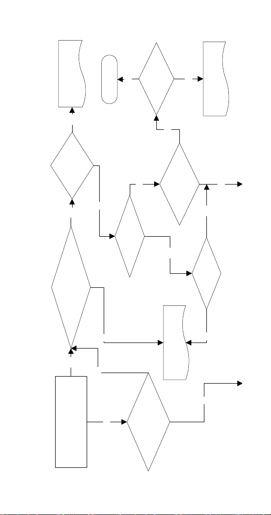
Refer to Alert/Error
Log
Yes
No
Install Ground
Unit has
adequate ground?
No
Yes
board diagnostics
Refer to display & control
Error Logged?
Is there an Alert or
No
Yes
Micro light flashing?
Does the ice machine start
when the Power button is pushed?
No
Yes
Yes
START
Is the display interface
No
energized and functioning?
No
Cycle Power to Board,
Yes
board diagnostics
Refer to display & control
control board?
Are there any lights
on or flashing on the
Yes
are lights flashing?
Yes
Flashing?
Display light
No
No
SYMPTOM #1 ICE MACHINE WILL NOT RUN
Part Number 000015430 Rev01 5/19 99
Page 94
Yes
No
dampers in place ?
All water curtains or
Install the water curtain /damper.
No
Bin switch light on ?
(Multi evap all lights on ? )
Yes
Yes
Yes
board diagnostics
Refer to display & control
No
Line voltage at wires
55 & 56 on 9 pin control
Yes
board connector ?
No
ice machine
Supply power to the
is good ?
Control board fuse
No
Replace fuse & determine which
component caused fuse to blow
100 Part Number 000015430 Rev01 5/19
Page 95
curtain/damper.
Replace the water
Refer to bin
switch diagnostics.
No
Yes
Yes
Yes
Is magnet on the
water curtain/damper
ice making
Press power button to start
Yes
Ice machine starts?
No
Test run ice machine
board diagnostics
Refer to display & control
Part Number 000015430 Rev01 5/19 101
Page 96

CYCLE
Ice Machine has a Long Freeze Cycle.
Ice Formation is Thick
or
Thin on Inlet or Outlet of Evaporator
or
Low Production
How to Use the Freeze Cycle Refrigeration System
Operational Analysis Table
GENERAL
These tables must be used with charts, checklists and
other references to eliminate refrigeration components
not listed on the tables and external items and problems
which can cause good refrigeration components to appear
defective.
The tables list five different defects that may affect the ice
machine’s operation.
NOTE: A low-on-charge ice machine and a starving
expansion valve have very similar characteristics and are
listed under the same column.
NOTE: Before starting, see “Before Beginning Service” for
a few questions to ask when talking to the ice machine
owner.
PROCEDURE
Step 1 Complete the “Operation Analysis” column.
Read down the left “Operational Analysis” column.
Perform all procedures and check all information listed.
Each item in this column has supporting reference material
to help analyze each step.
While analyzing each item separately, you may find an
“external problem” causing a good refrigerant component
to appear bad. Correct problems as they are found. If
the operational problem is found, it is not necessary to
complete the remaining procedures.
102 Part Number 000015430 Rev01 5/19
Page 97

Step 2 Enter Checkmarks (√).
Each time the actual findings of an item in the
“Operational Analysis” column matches the published
findings on the table, enter a Checkmark.
Example: Freeze cycle suction pressure is determined to be
low. Enter a Checkmark in the “low” column.
Step 3 Add the Checkmarks listed under each of the
four columns. Note the column number with the highest
total and proceed to “Final Analysis.”
NOTE: If two columns have matching high numbers,
a procedure was not performed properly, supporting
material was not analyzed correctly or the problem
component is not covered by the analysis table.
Before Beginning Service
Ice machines may experience operational problems
only during certain times of the day or night. A machine
may function properly while it is being serviced, but
malfunctions later. Information provided by the user can
help the technician start in the right direction, and may be
a determining factor in the final diagnosis.
Ask these questions before beginning service:
• When does the ice machine malfunction? (night, day,
all the time, only during the Freeze cycle, etc.)
• When do you notice low ice production? (one day a
week, every day, on weekends, etc.)
• Can you describe exactly what the ice machine seems
to be doing?
• Has anyone been working on the ice machine?
• During “store shutdown,” is the circuit breaker, water
supply or air temperature altered?
• Is there any reason why incoming water pressure
might rise or drop substantially?
Part Number 000015430 Rev01 5/19 103
Page 98
SINGLE EVAPORATOR, SINGLE EXPANSION VALVE
charted capacity.
Air-Temperature Entering Condenser _______________
NOTE: The ice machine is operating properly if the ice fill patterns is normal and ice production is within 10% of
Water Temperature Entering Ice Machine ___________
Published 24 hour ice production __________________
Calculated (actual) ice production _________________
-or-
Ice formation normal
-or-
Ice formation normal
Ice formation is extremely
thin on inlet of evaporator
evaporator
thin on outlet of
Ice formation is extremely
All installation and water related problems must be corrected before proceeding with chart.
evaporator
thin on outlet of
Ice formation is extremely
evaporator
No ice formation on entire
-or-
evaporator
No ice formation on entire
-or-
evaporator
No ice formation on entire
-or-
entire evaporator
No ice formation on the
Operational Analysis 1 2 3 4
Ice Production
Reference “Ice
Production Check” on
page 112
Installation and
Water System
Reference “Water
System Checklist” on
page 115
Ice Formation Pattern
Reference “Ice
Formation Pattern” on
104 Part Number 000015430 Rev01 5/19
page 115
Page 99
SINGLE EVAPORATOR, SINGLE EXPANSION VALVE
checklist to eliminate problems and/or components not listed on this table before proceeding.
If discharge pressure is High or Low refer to freeze cycle high or low discharge pressure problem
If suction pressure is High or Low refer to freeze cycle high or low suction pressure problem checklist
page 124 to eliminate problems and/or components not listed on this table before proceeding.
Suction pressure is
Suction pressure is
Suction pressure is
Suction pressure is
High
High
Low or Normal
High
Operational Analysis 1 2 3 4
1 minute Middle End
into cycle
Freeze Cycle
Discharge Pressure
________ _______ ______
Part Number 000015430 Rev01 5/19 105
Freeze Cycle
Suction Pressure
1 minute Middle End
________ _______ ______
Page 100
Inlet and outlet
within 7°F (4°C)
of each other
SINGLE EVAPORATOR, SINGLE EXPANSION VALVE
Inlet and outlet
within 7°F (4°C)
-or-
of each other
Inlet and outlet
not within 7°F (4°C)
-and-
of each other
Inlet and outlet
not within 7° F (4°C)
of each other
Inlet and outlet
within 7° F (4°C)
-and-
outlet
of each other
Inlet is warmer than
outlet
Inlet is colder than
Operational Analysis 1 2 3 4
Wait 5 minutes into the freeze cycle.
Compare temperatures of
evaporator inlet and evaporator
outlet.
Inlet T3 ____________° F (°C)
Outlet T4 __________ ° F (°C)
Difference
T3 & T4 ____________ ° F (°C)
Reference “Comparing Evaporator
Inlet and Outlet Temperatures -
Self-contained & Remote Condenser
Single Expansion Valve Machines” on
page 126
106 Part Number 000015430 Rev01 5/19
 Loading...