

Page 1
J RUE KOCN
INTRODUCCIÓN
Trípodes ligeros de video fabricado en fibra de carbono que combinan una gran estabilidad con una alta capacidad de carga y una gran altura máxima con un diseño
compacto, ergonómico y fácil de usar.
CARACTERÍSTICAS RESALTABLES
• semiesfera de 75mm (versión 535)
• semiesfera de 75/100mm (versión 536)
• semiesfera de 75/60mm (versiones MVT535AQ y MVT535HH)
• cada pata se puede configurar independientemente a 3 ángulos (23° - 50° - 70°)
• pies de goma con pinchós retráctiles
• conexión para correa de transporte (opcional)
• forros térmicos (versión MVT535AQ)
CONFIGURACIÓN
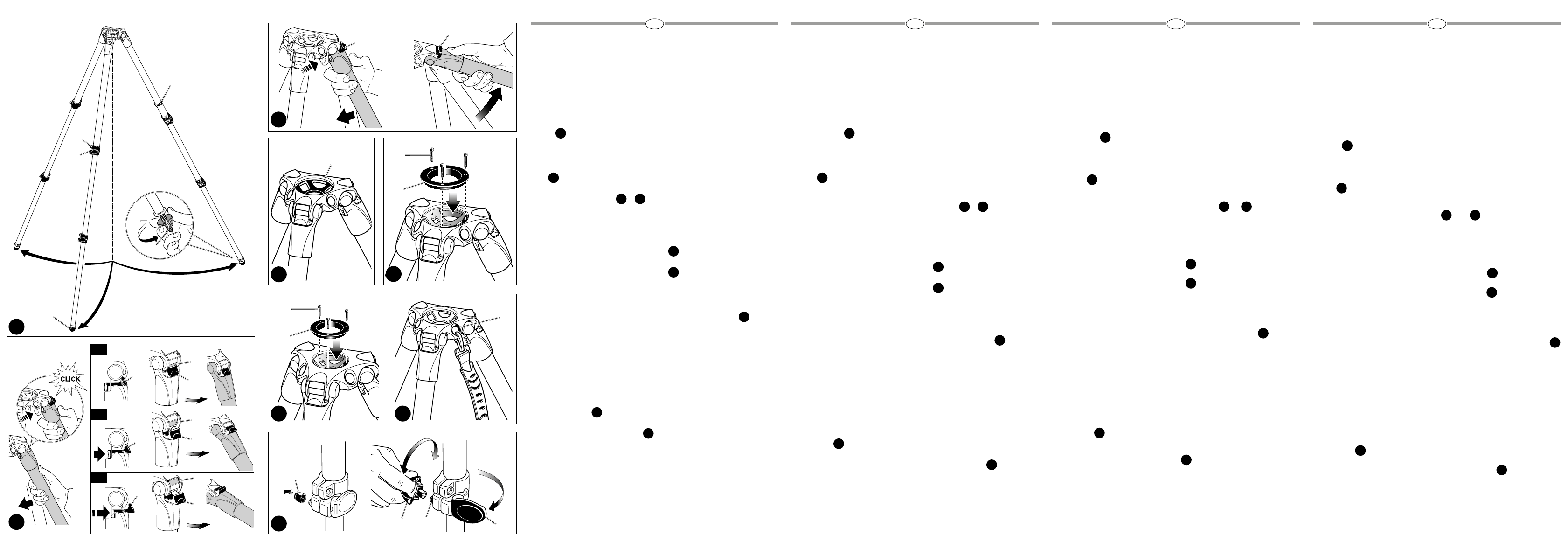
Abra las 3 patas del trípode.
Para ajustar la altura del trípode, cada pata tiene extensiones telescópicas que se
pueden liberar abriendo la pinza “A” sobre el collar de bloqueo “B”. Cuando se alcanza la altura requerida, cierre el bloqueo de la pinza “A”.
PIES
1
El trípode tiene pies de goma “Q” con pinchos retráctiles “R” para uso en exteriores.
AJUSTE DEL ÁNGULO DE LA PATA
Cada pata se puede configurar a 3 ángulos (X -Y- Z) – ver figura 2
Para cambiar el ángulo de una pata, cierre la pata ligeramente, presione el botón “C”
para seleccionar el nuevo ángulo, luego abra la pata.
El ángulo de cada pata se puede ajustar independientemente de las otras dos patas.
La última posición permite alcanzar el nivel del suelo.
MONTANDO LA RÓTULA – MODELO 535
El trípode tiene la semiesfera “P” para montar la rótula
MONTANDO LA RÓTULA – MODELO 536
El trípode está diseñado para rótulas con semiesfera de 100mm o 75mm. Para montar
la rótula con semiesfera de 75mm, instale el adaptador “N“ (proporcionado) al trípode
con los tres tornillo “M”.
El adaptador de 75 mm “N” no se incluye si el trípode viene preensamblado con una
rótula de 100mm.
MONTANDO LA RÓTULA – MODELOS MVT535AQ y MVT535HH
El trípode está diseñado para rótulas con semiesfera de 75mm o 60mm. Para montar
la rótula con semiesfera de 60mm, instale el adaptador "D" (proporcionado) al trípode
con los tres tornillo “E”.
El adaptador de 60 mm “D” no se incluye si el trípode viene preensamblado con una
rótula de 75mm.
NOTA
También es posible montar una rótula sin semiesfera (base plana con fijación hembra
de 3/8”) en el trípode mediante una semibola que está disponible opcionalmente:
-520BALL Ø75 para el trípode 535
-500BALL Ø100 o 520BALL Ø75 para el trípode 536
-520BALL Ø75 para los trípodes MVT535AQ y MVT535HH
TRANSPORTE
El conector “T” para una correa de transporte opcional
AJUSTE DE LA TENSIÓN DEL BLOQUEO DE LAS PATAS
Si las extensiones telescópicas de las patas no quedan bien fijadas, incluso después
de haber cerrado la pinza de bloqueo“A”, la tensión de bloqueo necesita ser ajustada.
Para hacerlo:
-quite el tapón “K”
-libere la pinza de bloqueo “A”
-atornille la rosca “V” en el sentido de las agujas del reloj, usando la llave especial “W”
que se proporciona en una de las patas del trípode.
Normalmente un tercio de rosca será suficiente para conseguir una tensión de bloqueo correcta.
1
Y
2 3
4
5
6
7
8
はじめ に
本商品はカーボンファイバー製の軽量ビデオ三脚で、優れた安定性と耐荷重性能、傑出した
最大高を誇るとともに、人間工学に基づいた使いやすくコンパクトなデザインを採用してい
ます。
主な特長
•• ボール径•75mm(535モデル)
•• ボール径•75/100mm(536モデル)
•• ボール径•75/60mm(MVT535AQおよびMVT535HHモデル)
•• 脚は、それぞれ3種類の開脚角度(23°、50°、70°)に設定可能
•• リトラクタブルスパイク石突付きラバー製の足先
•• キャリングストラップ用取り付けねじ(ストラップは別売り)
•• レッグウォーマー(MVT535AQモデル)
組み立て
3本の脚を開きます。
各脚を伸縮させて三脚の高さを調整します。固定用カラー"B"上のレバー"A"を回転すると、
脚が伸縮するので、希望の高さになったところで、レバー"A"をロックします。
三脚
ラバー製の足先"Q"を備えた三脚で、屋外での使用のためリトラクタブルスパイク石突"R"が
付いています。
脚の角度調整
脚は、それぞれ3種類の開脚角度(X、Y、Z)に設定できます。図2参照。
脚の角度を変更するには、中央に向けてやや脚を閉じ、ボタン"C"を押して角度を選択して
から脚を開きます。
それぞれの脚の角度は、他の脚とは別々に変更可能です。
Zの角度にすると、床の高さでカメラを固定できます。
カメラの 取り付け 53 5モデ ル
三脚には、カメラ取り付け用のボール"P"が付いています。
カメラの 取り付け 53 6モデ ル
このタイプの三脚には75mmと100mmのボールヘッドを取り付けることができます。75mm
のボールヘッドを取り付ける場合は、ネジ"M"を3本使用して三脚に付属のアダプタ"N"を取
り付けま す。
100mmのボールヘッドで組立て済みの三脚には、75mm用のアダプタ"N"は含まれていま
せん。
カメラの取り付けMVT535AQおよびMVT535HHモデル
このタイプの三脚には60mmと75mmのボールヘッドを取り付けることができます。60mm
のボールヘッドを取り付ける場合は、ネジ"E"を3本使用して三脚に付属のアダプタ"D"を取
り付けま す。
75mmのボールヘッドで組立て済みの三脚には、60mm用のアダプタ"D"は含まれていませ
ん。
注
オプションで販売しているハーフボールを利用すれば、ボールヘッド以外(3/8インチのメス
コネクタ付きフラットベース)の取り付けも可能です。
持ち運び
三脚にはオプションのキャリングストラップを取り付けるためのアタッチメント"T"が付いて
います。
脚固定張力調整
固定レバー"A"を締めつけた後も脚の伸縮が安定しないようであれば、固定張力を調整する
必要があります。
以下の方法で調整します。
通常は、1/3ほど回すだけで正しい固定張力に調整できます。
1
1
&
2 3
4
5
6
•- 535モデルの三脚には直径75mmのボール520
•- 536モデルの三脚には直径100mのボール500または直径75mmのボール520
•- MVT535AQおよびMVT535HHモデルの三脚には直径75mmのボール520
7
8
•- キャップ" K " を 取り外しま す。
•- 固定レバー"A"を解除します。
•- 3本の脚の1本に付属している特殊キー"W"を使って、ネジVを時計回りに回します。
说明
这款轻质碳纤维摄像三脚架将出众的稳定性、高承载能力、符合人体工程学的最大高
度以及易于使用的紧凑型设计完美地结合于一体。
主要参数:
•• 75mm球碗(535型号)
•• 75/100mm球碗(536型号)
•• 75/60mm球碗(MVT535AQ和MVT535HH型号)
•• 每个脚管可单独设置成三种角度(23°•-•50°•-•70°)
•• 橡胶脚板带有可伸缩脚钉
•• 配件螺纹用于安装三脚架肩带(选配)
•• 脚管防冻套(MVT535AQ型号)
安装
1
打开3个三脚架脚管。
要调节三脚架的高度,可使用每个脚管上带有的可伸缩延展件,其可通过旋转锁
环“B”上的旋转杆“A”松开。达到所需高度时,锁定旋转杆“A”即可。
脚板
1
该三脚架配有橡胶脚板“Q”,其带有的可伸缩脚钉“R”可供外部使用。
脚管角度调节装置
每个脚管可设置成3种扩展角度(X•–•Y•–•Z)参见图2。
要更改脚管上的角度,将脚管稍稍向中轴闭合,并按下按钮“C”来选择新的脚管角
度,然后打开脚管。
可独立于另外两个脚管之外对各个脚管的角度进行调节。
最后一个位置可使脚管与地板保持水平。
安装相机云台 535 型号
三脚架带有用来安装云台的球碗“P”。
安装相机云台 536型号
三脚架设计用于安装100mm或75mm球型云台。要安装75mm球型云台,用三个螺
钉“M”将转接器“N”(随三脚架一起提供)固定在三脚架上。
如三脚架作为预装配套装配备有100mm球型云台,则不配有75mm转接器“N”。
安装相机云台 —MVT535AQ 和MVT535HH型号
三脚架设计用于搭配75mm或60mm球型云台。要安装60mm球型云台,用三个螺
钉“E”将转接器“D”(随三脚架一起提供)固定在三脚架上。
如三脚架作为预装配套装配备有75mm球型云台,则不配有60mm转接器“D”。
注
还可以使用作为选件提供的半球,在三脚架上安装非球型云台(带3/8”母接头的平底
座)。
•- 535三脚架搭配520BALL•Ø75球型云台
•- 536三脚架搭配500BALL•Ø100球型云台或520BALL•Ø75球型云台
•- MVT535AQ和MVT535HH三脚架搭配520BALL•Ø75球型云台
搬运
7
三脚架带有配件“T”,用于安装可选配件肩带。
脚管锁紧力调节装置
即便已将锁紧杆“A”拧紧,如可伸缩脚管延展件发生滑动,必须调节锁紧力。
要调节锁紧力:
•- 拆下盖帽“K”;
•- 松开锁紧杆“A”;
•- 使用其中一个三角架脚管上的专用按键“W”顺时针转动螺钉“V”。
通常,旋转三分之一周便足以获得合适的锁紧力。
和
2 3
4
5
8
6
제품설명서
경량의 카본 파이버 비디오 트라이포드로 뛰어난 안정성, 높은 최대 적재 중량과 높이
를 가졌으며 컴팩트한 크기에 인체공학적으로 디자인되어 사용하기 편리합니다.
주요 기능
• 75mm 볼 (535 버전)
• 75/100mm 볼 (536 버전)
• 75/60mm 볼 (MVT535AQ와 MVT535HH 버전)
• 각 다리마다 3가지의 다른 각도로 설치가 가능 (23° - 50° - 70°)
• 고무 핏 이 있는 개폐식 스파이크
• 휴대 스트랩(옵션)을 연결할 수 있는 나사
• 레그워머 (MVT535AQ 버전)
설치
1
트라이포드 다리를 모두 열어줍니다.
각 다리의 락킹 마디 “B”에 있는 레버 “A”를 풀어 각 다리의 길이를 조정하고 원하는 트
라이포드의 높이로 설정이 끝나면 레버 “A”를 잠급니다.
핏
1
트라이포드는 개폐식의 스파이크 “R”을 포함하고 있는 고무 핏 “Q”를 가지고 있습니다.
다리각도 조절
각 다리마다 3가지의 다른 각도(X - Y - Z)로 설치가 가능합니다 – figure 2 참조
다리 각도조절 시, 먼저 트라이포드의 중앙부로 다리를 살짝 밀고 버튼 “C”를 눌러 원
하는 새로운 각도를 선택한 이후 다리를 펴줍니다.
각 다리의 각도는 나머지 두 다리와는 상관없이 조정이 가능합니다.
가장 마지막 각도를 사용하면 그라운드 레벨로 트라이포드를 설치 할 수 있습니다.
카메라 헤드 장착하기 – 535 모델
트라이포드에는 헤드 장착을 위한 볼 “P”가 있습니다.
카메라 헤드 장착하기 – 536 모델
100mm 또는 75mm 볼헤드와 함께 사용되도록 설계된 트라이포드 입니다. 75mm
볼헤드를 장착하기 위해서는 아답터 “N”(포함사항)을 세 개의 나사 “M”을 사용하여 트
라이포드에 장착합니다.
100mm 볼헤드와 트라이포드가 미리 조립된 키트 제품에는 75mm 아답터 “N”이 포
함되어있지 않습니다.
카메라 헤드 장착하기 – MVT535AQ 와 MVT535HH 모델
75mm 또는 60mm 볼헤드와 함께 사용되도록 설계된 트라이포드 입니다. 60mm 볼
헤드를 장착하기 위해서는 아답터 “D”(포함사항)을 세 개의 나사 “E”을 사용하여 트라
이포드에 장착합니다.
75mm 볼헤드와 미리 조립된 키트 제품에는 60mm 아답터 “D”가 포함되어있지 않
습니다.
노트
볼 헤드가 아닌 일반 헤드(플랫 베이스 3/8” 암나사)의 경우 아래 옵션 사항과 같이 하
프 볼을 사용하여 트라이포드에 장착 가능합니다.
- 535 트라이포드용 520BALL Ø75 볼
- 536 트라이포드용 500BALL Ø100 볼 또는 520BALL Ø75 볼
- MVT535AQ와 MVT535HH 트라이포드 용 520BALL Ø75 볼
휴대방법
트라이포드는 휴대 스트랩(옵션) 연결고리인 “T”가 있습니다.
다리 락킹 강도 조절
만일 락킹 레버 “A”를 잠근 이후에도 설정된 다리 길이로 고정되지 않고 미끄러진다면
다리 락킹의 강도를 조절하면 됩니다.
락킹 강도를 조절하려면:
- 마개 “K”를 열어줍니다.
- 락킹 레버 “A”를 열어줍니다
- 트라이포드와 함께 제공된 키 “W”를 이용하여 나사 “V”를 시계방향으로 돌려줍니다.
보통 나사를 3번 돌리면 알맞은 정도의 락킹 강도로 조정됩니다.
&
2 3
4
5
6
7
8
ОБЩЕЕ ОПИСАНИЕ
Легкий угле пластиковый видео штатив, вобравший в себя великолепную устойчивость, большую грузоподъемность и максимально большую высоту с эргономичным. Легким в использовании и компактным дизайном.
ОСНОВНЫЕ ХАРАКТЕРИСТИКИ
• 75мм чаша (535 версия)
• 75/100 мм чаша (536 версия)
• 75/60 мм чаша (MVT535AQ и MVT535HH версии)
• каждая нога может быть установлена независимо 3 степени 23-50-70 градусов
• резиновые наконечники с убирающимися заостренными концами
• специальное крепление для переносного ремня (опция)
• защитные чехлы на ножках штатива (MVT535AQ версия)
УСТАНОВКА
Откройте 3 ноги штатива. для того, чтобы настроить высоту штатива, каждая нога
1
имеет телескопическое увеличение высоты, которое может быть регулироваться путем вращения рычага "А" на закрывающем кольце "В". Когда нужная высота
установлена, закройте рычаг "А".
НАКОНЕЧНИКИ
Штатив имеет резиновые наконечники "Q" с убирающимися шипами "R" для внеш-
1
него использования.
НАСТРОЙКА УГЛА НОГИ
Каждая нога может быть установлена под 3 наличными углами (X - Y - Z ) - смотри
И
2 3
рисунок 2.
Для того, чтобы сменить угол ноги, осторожно закройте ногу к центру, нажмите на
кнопку "С" для выбора нового угла ноги, затем откройте ногу.
Угол каждой ноги может быть настроен независимо от других ног.
Последнее положение позволяет достигнуть уровня пола
УСТАНОВКА ГОЛОВКИ НА МОДЕЛИ 535
Штатив имеет чашу "Р" для установки головки
УСТАНОВКА ГОЛОВКИ ДЛЯ МОДЕЛИ 536
Штатив предназначен для 100мм или 65мм шаровых головок. Для установки 75мм
4
5
шаровой головки, соедините прилагаемый к поставке адаптер "N" к штативу тремя болтами "М".
75мм адаптер "N" не входит в комплект поставки, если штатив поставляется с заранее пред установленной 100мм чашей.
УСТАНОВКА ГОЛОВКИ ДЛЯ МОДЕЛЕЙ MTV 535AQ И MVT535HH
Штатив предназначен для чаш размером 75 или 65мм. Для установки 60мм чаши,
6
соедините адаптер "D" к штативу тремя болтами "E".
60мм адаптер "D" не входит в комплект поставки, если штатив поставляется с
предустановленной 75 мм шаровой головкой.
ПРИМЕЧАНИЕ
Также можно устанавливать головки на штативы без чаши (плоская основа с резьбой 3/8 дюйма), используя адаптер, который имеется в наличие в качестве дополнительной опции.
-520 адаптер 75 мм чаша для 535 штатива
-500 адаптер 100 мм чаша или 520 адаптер 75 мм чаша для 536 штатива
-520 адаптер 75 мм чаша для MTV535AQ и MVT535HH штативов
ПЕРЕНОСКА
Штатив имеет специальное кольцо "Т" для переносного ремня, поставляемого
7
дополнительно.
НАСТРОЙКА БЛОКИРОВКИ ЗАМКА НОГИ
Если телескопическая ножка сдвинется после затягивания рычага "А", блокировк у
8
замка нужно настроить.
для того, чтобы сделать это:
-снимите колпачек "K"
-ослабьте рычаг "А"
-поверните болт "V" по часовой стрелке специальным поставляемым ключом "W"
на одной из ног штатива.
Обычно трети поворота достаточно, чтобы достичь правильной блокировки замка
Cod. 535,50 - 06/14 Copyright © 2014 Manfrotto Bassano Italy
INSTRUCTIONS
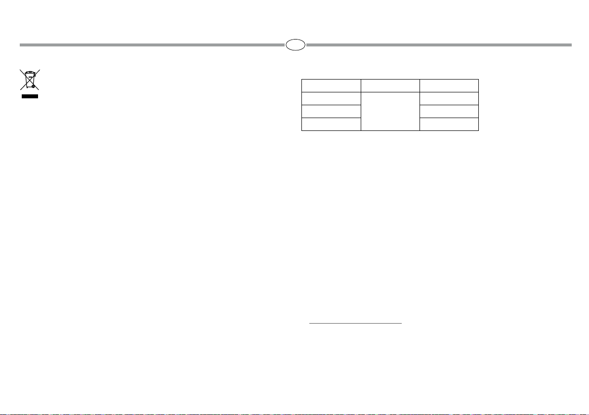
171 cm 2,3 kg 20 kg
535
67.3” 5 lbs 44.1 lbs
203 cm 3,25 kg 25 kg
536
80” 7.1 lbs 55.1 lbs
MVT535AQ
MVT535HH
171 cm 3,25 kg 20 kg
67.3” 7.1 lbs 44.1 lbs
25 cm 1,2 kg 20 kg
9.84” 2.6 lbs 44.1 lbs
Page 2
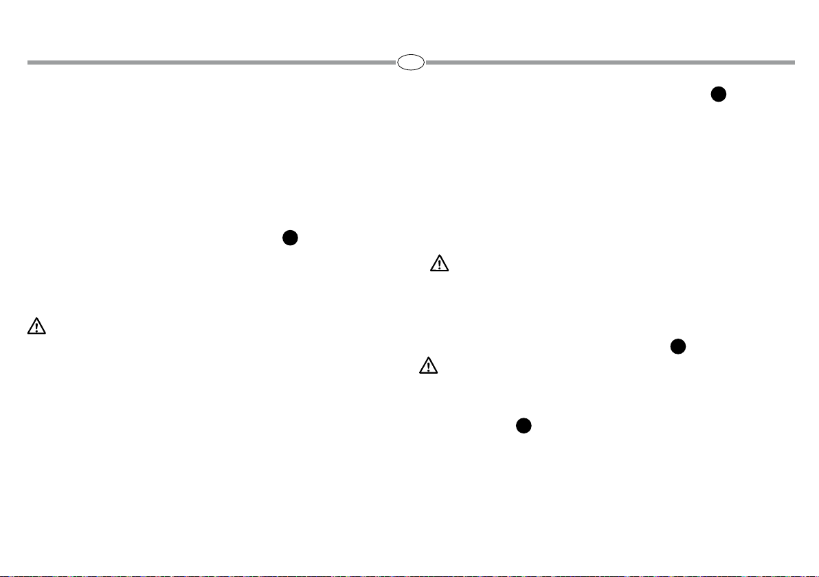
1
C
C
W
3
2
1
B
A
P
M
N
Q
R
4
Q
E
5
T
1
D
X
X
C
Y
C
C
Y
6 7
C
3
1
K
2
Z
Z
C
INTRODUCTION
Lightweight carbon fiber video tripod that combines great stability, high load capacity
and great max height with an ergonomic and easy-to-use and compact design.
KEY FEATURES
• 75mm bowl (535 version)
• 75/100mm bowl (536 version)
• 75/60mm bowl (MVT535AQ and MVT535HH versions)
• Each leg can be independently set at 3 angles (23° - 50° - 70°)
3
• Rubber feet with retractable spikes
• Attachment thread for carrying strap (optional)
• Leg warmers (MVT535AQ version)
SET UP
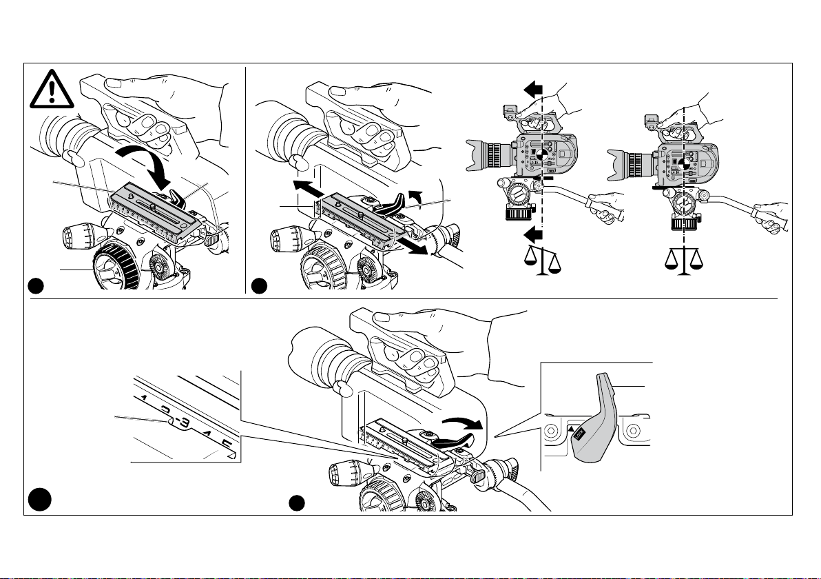
Open the 3 tripod legs.
To adjust the height of the tripod, each leg has telescopic extensions that can be
released by rotating lever “A” on the locking collar “B”. When the required height is
achieved, lock lever “A”.
FEET
The tripod has rubber feet “Q” with retractable spikes “R” for external use.
LEG ANGLE ADJUSTMENT
Each leg can be set at 3 spread angles (X - Y - Z) - see figure 2
To change the angle on a leg, close the leg towards the centre slightly, press button
“C” to select the new leg angle, then open the leg.
The angle of each leg can be adjusted independently of the other two legs.
The last position allows to achieve the floor level.
MOUNTING A CAMERA HEAD - 535 MODEL
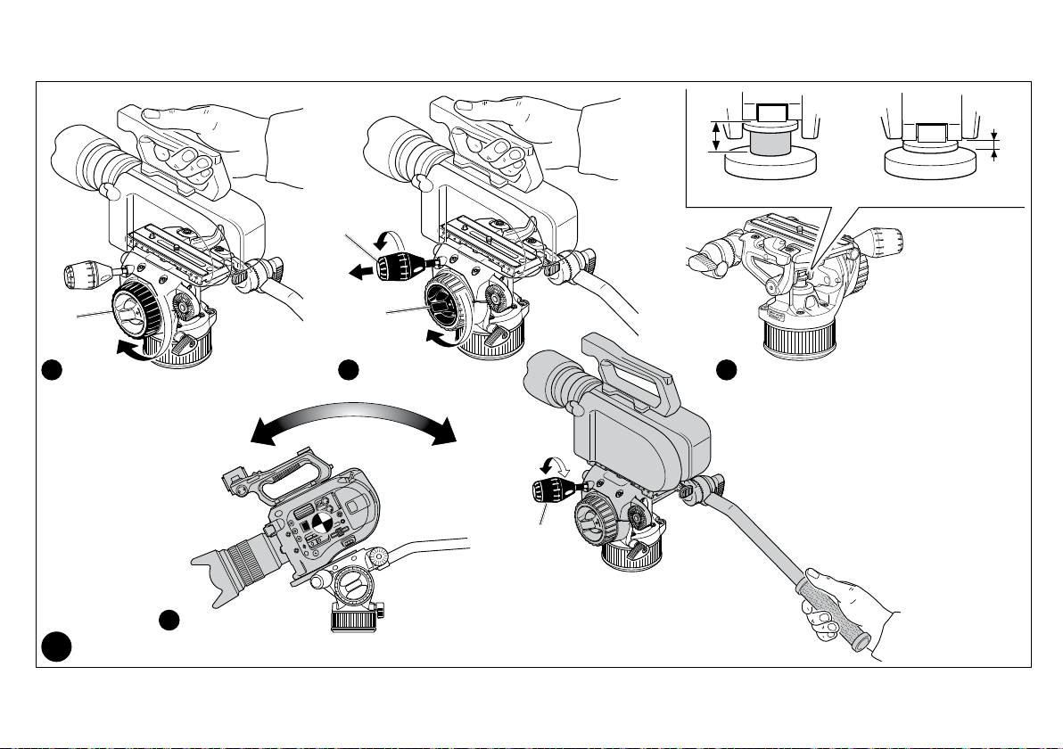
The tripod has bowl “P” for mounting head
MOUNTING A CAMERA HEAD - 536 MODEL
The tripod is designed for 100mm or 75mm ball heads. To mount 75mm ball heads,
attach the adapter “N” (provided) to the tripod with the three screws “M”.
The 75mm adapter “N” is not included if the tripod is supplied as a pre-assembled kit
with a 100mm ball head.
MOUNTING A CAMERA HEAD - MVT535AQ & MVT535HH MODELS
The tripod is designed for 75mm or 60mm ball heads. To mount 60mm ball heads,
attach the adapter “D” (provided) to the tripod with the three screws “E”.
The 60mm adapter “D” is not included if the tripod is supplied as a pre-assembled kit
with a 75mm ball head.
NOTE
It is also possible to mount non ball (flat base with 3/8” female fitting) heads on the
tripods by using a half ball, which is available as option.
TRANSPORTATION
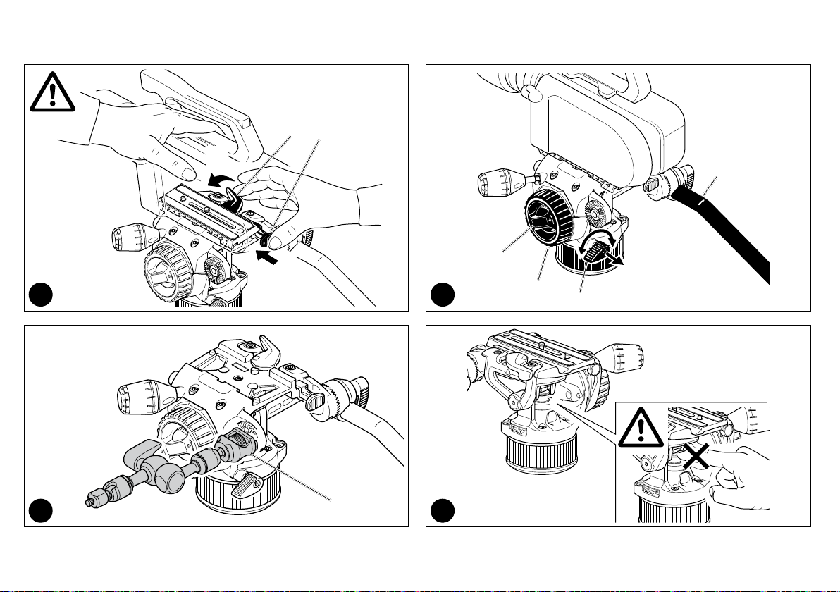
The tripod has an attachment “T” for optional carrying strap
LEG LOCK TENSION ADJUSTMENT
If the telescopic leg extensions slip even after having tightened the locking lever “A”,
the locking tension will need to be adjusted.
In order to do this:
Normally a third of a turn will be sufficient to achieve the correct locking tension.
1
1
2 3
-520BALL Ø75 ball for 535 tripod
-500BALL Ø100 ball or 520BALL Ø75 ball for 536 tripod
-520BALL Ø75 ball for MVT535AQ and MVT535HH tripods
7
-remove cap “K”
-release lock lever “A”
-turn the screw “V” clockwise using the special key “W” provided on one of the tripod
legs.
C
2
8
X
V
A
GB I F D
EINFÜHRUNG
Leichtes Video-Stativ aus Kohlenstofffaser, das hohe Stabilität, Belastungsfähigkeit
und große Maximalhöhe mit einem ergonomischen, einfach zu bedienenden und kompakten Design verbindet.
HAUPTEIGENSCHAFTEN
• 75 mm Schale (Version 535)
• 75/100 mm Schale (Version 536)
• 75/60mm Schale (Version MVT535AQ und MVT535HH)
• jedes Stativbein kann individuell auf 3 verschiedene Winkel eingestellt werden (23°
- 50° - 70°)
• Gummifüße mit ausziehbaren Spikes
• Gewinde zur Befestigung eines Trageriemens (optional)
• Beinschützer (Version MVT535AQ)
AUFBAU
Ziehen Sie die 3 Stativbeine auseinander.
Um die Höhe des Stativs einzustellen, ist jedes Teleskop-Bein ausziehbar, indem der
Hebel “A” an dem Sicherungsring “B” verstellt wird. Ist die gewünschte Höhe erreicht,
stellen Sie Hebel “A” fest.
FÜSSE
Das Stativ verfügt zur Nutzung im Außenbereich über Gummifüße “Q” mit ausziehbaren Spikes “R”.
EINSTELLUNG DER WINKEL DER BEINE
Jedes Bein kann auf 3 verschiedene Winkel eingestellt werden (X -Y- Z) – siehe Abb. 2
Um einen anderen Winkel einzustellen, ziehen Sie das entsprechende Bein leicht an,
drücken den Knopf “C” zur Wahl des gewünschten Winkels und ziehen das Bein wieder auseinander.
Der Winkel kann bei jedem Bein individuell eingestellt werden.
Mit dem größten Winkel wird der Boden erreicht.
BEFESTIGUNG EINES KAMERAKOPFES – MODELL 535
Das Stativ verfügt über eine Schale “P” zur Befestigung eines Kamerakopfes.
BEFESTIGUNG EINES KAMERAKOPFES - MODELL 536
Das Stativ ist für Kugelköpfe von 100 mm oder 75 mm konzipiert. Um einen Kugelkopf
von 75 mm anzubringen, befestigen Sie den mitgelieferten Aufsatz “N” mit den drei
Schrauben “M” an dem Stativ.
Der 75mm-Adapter “N” ist nicht im Lieferumfang enthalten, wenn es sich um ein Stativ
in einem vormontierten Bausatz mit einem 100mm-Kugelkopf handelt.
BEFESTIGUNG EINES KAMERAKOPFES - Modelle MVT535AQ & MVT535HH
Das Stativ ist für Kugelköpfe von 75 mm oder 60 mm konzipiert. Um einen Kugelkopf
von 60 mm anzubringen, befestigen Sie den mitgelieferten Aufsatz “D” mit den drei
Schrauben “E” an dem Stativ.
Der 60mm-Adapter “D” ist nicht im Lieferumfang enthalten, wenn es sich um ein Stativ
in einem vormontierten Bausatz mit einem 75mm-Kugelkopf handelt.
HINWEIS
Es ist ebenfalls möglich, Köpfe, die keine Kugelköpfe sind (Flachboden mit
3/8”-Schrauben), an dem Stativ zu befestigen, indem Halbkugeln verwendet werden,
die optional erhältlich sind.
-520BALL Kugel Ø75 für Stativ 535
-500BALL Kugel Ø100 oder 520BALL Kugel Ø75 für Stativ 536
-520BALL Kugel Ø75 für Stative MVT535AQ und MVT535HH
TRANSPORT
Das Stativ verfügt über die Befestigung “T” für einen optionalen Trageriemen
EINSTELLUNG DER VERSCHLUSSSPANNUNG DER BEINE
Wenn die ausziehbaren Teleskop-Beine nicht halten, obwohl der Sicherungshebel “A”
festgestellt wurde, muss die Verschlussspannung eingestellt werden. Dazu:
-Nehmen Sie den Deckel “K” ab
-Lösen Sie den Sicherungshebel “A”
-Drehen Sie die Schraube “V” an einem der Beine mit dem mitgelieferten Spezialschlüssel “W” im Uhrzeigersinn.
Meist genügt eine Drittelumdrehung, um die richtige Verschlussspannung zu erhalten.
1
1
7
&
INTRODUZIONE
Leggero treppiede in fibra di carbonio che combina grande stabilità, elevata portata e
notevole altezza massima, di concezione compatta, ergonomica e di facile uso.
CARATTERISTICHE PRINCIPALI:
• Culla da 75mm (versione 535)
• Culla da 75/100mm (versione 536)
• Culla da 75/60mm (versioni MVT535AQ e MVT535HH)
• Apertura indipendente delle gambe su 3 angolazioni (23° - 50° - 70°)
• Piedini in gomma retraibili su puntali
• Attacco per cinghia da trasporto (opzionale)
• Impugnature morbide (versione MVT535AQ)
PREPARAZIONE
Divaricare le 3 gambe.
Per regolare l’altezza del treppiede, ogni gamba dispone di allungamenti telescopici
che si possono liberare ruotando la leva “A” sul manicotto “B”. Ottenuta l’altezza
desiderata, bloccare la leva “A”.
PIEDINI
Il treppiede è dotato di piedini in gomma “Q” con puntai retraibili “R” per l’uso in
esterni.
REGOLAZIONE DELL’ANGOLAZIONE DELLE GAMBE
Ciascuna gamba prevede 3 angolazioni d’apertura (X -Y- Z) - vedere figura 2.
Per cambiare l’angolazione di una gamba, chiuderla leggermente verso la colonna
centrale e premere il pulsante di bloccaggio “C”. Selezionare la nuova angolazione e
poi rilasciare il pulsante aprendo la gamba verso la posizione desiderata.
4
5
6
8
Ogni gamba può essere angolata in modo indipendente dalle altre due.
La posizione di massima divaricazione consente le riprese raso terra.
MONTAGGIO DI UNA TESTA – MODELLO 535
Il treppiede è dotato di culla “P” per montare la testa
MONTAGGIO DI UNA TESTA – MODELLO 536
Il treppiede è progettato per teste con semisfera da 100mm oppure 75mm. Per montare una testa con semisfera da 75mm, attaccare l’adattatore “N” (in dotazione) al
treppiede con le tre viti “M”.
L'adattatore “N” da 75mm non è incluso se il treppiedi è fornito come kit preassemblato con testa dotata di semisfera da 100mm.
MONTAGGIO DI UNA TESTA – MVT535AQ & MVT535HH MODELS
Il treppiede è progettato per teste con semisfera da 75mm oppure 60mm. Per montare
una testa con semisfera da 60mm, attaccare l’adattatore “D” (in dotazione) al treppiede con le tre viti “E”.
L'adattatore “D” da 60mm non è incluso se il treppiedi è fornito come kit preassemblato con testa dotata di semisfera da 75mm.
NOTA
É anche possibile montare teste senza semisfera (base piatta con attacco femmina da
3/8”) impiegando un adattatore a semisfera, opzionale.
-Semisfera 520BALL Ø75 per treppiede 535
-Semisfera 500BALL Ø100 o semisfera 520BALL Ø75 per treppiede 536
-520BALL Ø75 per treppiedi MVT535AQ e MVT535HH.
TRASPORTO
Il treppiede è dotato di attacco “T” per cinghia da trasporto opzionale
REGOLAZIONE DELLA TENSIONE DI BLOCCO DELLE GAMBE
Se le sezioni telescopiche tendono a scivolare anche dopo aver serrato le leve “A”,
occorre ripristinare un’adeguata forza di bloccaggio. A questo scopo:
-rimuovere la protezione “K”
-allentare la leva di bloccaggio “A”
-avvitare la vite “V” in senso orario con la speciale chiave “W” fissata ad una delle
gambe del treppiede.
Normalmente sarà sufficiente la rotazione di un terzo di giro per ripristinare la corretta
tensione di bloccaggio.
1
1
E
2 3
4
5
6
7
8
INTRODUCTION
Ces trépieds vidéo légers en fibre de carbone combinent une grande stabilité, une
capacité de charge élevée et une hauteur maximale élevée avec un design ergonomique, compact et facile à utiliser.
CARACTÉRISTIQUES PRINCIPALES
• Bol de 75mm (modèle 535 uniquement)
• Bol de 75/100mm (modèle 536 uniquement)
• Bol de 75/60mm (modèles MVT535AQ et MVT535HH)
• 3 angles d’ouverture possibles des jambes (23° - 50° - 70°), de façon indépendante
• Embouts en caoutchouc et pointes rétractables
• Anneau pour sangle de transport (en option)
• Poignées chauffe mains (modèle MVT535AQ)
PRÉPARATION
Ouvrez les 3 jambes du trépied.
Pour régler la hauteur du trépied, déployez les sections télescopiques des jambes en
ouvrant les leviers de blocage "A" situés sur les bagues "B". Une fois votre trépied à
la hauteur souhaitée, bloquez les jambes à l’aide des leviers "A".
EMBOUTS
Les trépieds sont équipés d’embouts en caoutchouc "Q" avec pointes rétractables
"R" spécialement conçus pour une utilisation en extérieur.
RÉGLAGE DE L’ANGLE D’OUVERTURE DES JAMBES
Chaque jambe peut être ouverte à 3 angles différents (X -Y- Z) (voir figure 2).
Pour modifier l’angle d’ouverture d’une jambe, repliez légèrement la jambe vers le
centre du trépied, appuyez sur le bouton "C" afin de sélectionner l’angle d’ouverture
souhaité, puis ouvrez à nouveau la jambe.
L’angle d’écartement de chaque jambe peut être réglé indépendamment des autres.
L’angle d’écartement le plus grand permet des prises de vues à ras du sol.
MONTAGE D’UNE ROTULE – MODÈLE 535
Le trépied 535 est doté d’un bol "P" permettant la fixation d’une rotule.
MONTAGE D’UNE ROTULE – MODÈLE 536
Le trépied 536 est conçu pour les rotules livrées avec une boule de 100mm ou 75mm.
Pour monter une rotule à boule de 75mm, fixez l’adaptateur "N" (fourni) au trépied à
l’aide des trois vis "M".
L'adaptateur 75 mm "N" n'est pas fourni si le trépied est livré sous forme de kit préassemblé avec une rotule 100 mm.
MONTAGE D’UNE ROTULE – MODELES MVT535AQ & MVT535HH
Le trépied est conçu pour les rotules livrées avec une boule de 75mm ou 60 mm.
Pour monter une rotule à boule de 60mm, fixez l’adaptateur "D" (fourni) au trépied à
l’aide des trois vis "E".
L'adaptateur 60 mm "D" n'est pas fourni si le trépied est livré sous forme de kit préassemblé avec une rotule 75 mm.
REMARQUE
Il est également possible de fixer des rotules plates (comprenant un filetage de 3/8")
au trépied à l’aide d’une demi-boule (en option).
-520BALL boule de Ø75 pour le trépied 535
-500BALL boule de Ø100 ou 520BALL boule de Ø75 pour le trépied 536
-520BALL boule de Ø75 pour les trépieds MVT535AQ et MVT535HH
TRANSPORT
Les trépieds sont équipés d’un anneau "T" auquel une sangle de transport peut être
attachée.
RÉGLAGE DU BLOCAGE DES SECTIONS
Si après avoir bloqué les jambes avec le levier de blocage "A", les sections télescopiques glissent légèrement, il faut procéder au réglage du système de blocage des
jambes. Pour cela:
-retirez le cache "K",
-débloquez le levier "A",
-tournez la vis "V" dans le sens des aiguilles d’une montre à l’aide de la clé spéciale
"W" fournie.
Un tiers de tour doit suffire pour rendre le système de blocage à nouveau efficace.
1
1
ET
2 3
4
5
6
7
8
UND
2 3
4
5
6
8
Page 3
INSTRUCTIONS
MVHN8AH
14,8 cm 2,2 kg 8 kg
5.8" 4.8 lbs 17.6 lbs
Page 4

Y
F
K
X
CR1220
W
8 mm
max
H
1
D
A
U
2 3
3A 3B
F
W
8 mm
max
3C
2
8 mm
max
F
Page 5
6 5 4 3 2 1 <> -1 -2 -3 -4 -5 -6
C
B
4A 4B
4
G
5 6
S
Z
X
1
S/Z
L
K
2
3
Page 6
7A
1
L
Q
M
3
L
7B
2
M
M
R
7
7C
4
4
Page 7
2
AA
8,0 kg - 17.6" 0 kg
3
N
BB
8A
Q
1
8D
8
P
4
8B 8C
N
5
Page 8
M
T
2
1
9 10
J
1211
6
A
E
P
Q
V
Page 9

INDEX
GB
I
D
F
E
CN
KO
J
RU
EU DECLARATION OF CONFORMITY
KOREA CERTIFICATION
pag. 8 - 11
pag. 12 - 15
pag. 16 - 20
pag. 21 - 25
pag. 26 - 29
pag. 30 - 32
pag. 33 - 36
pag. 37 - 40
pag. 41 - 44
pag. 45
pag. 46
7
Page 10
GB
INTRODUCTION
Designed for ENG video cameras and interchangeable lens camcorders or DSLRs up
to 8 kg (17.6 lbs). Declared at 20°C and 55mm C.o.g.
For any uses other than those intended, in order for proper performance and safety of
use to be guaranteed, please contact your reseller or the manufacturer directly via the
Contact us section on manfrotto.com.
The product is intended for professional use.
KEY FEATURES
• Quick release sliding plate for balancing the camcorder
• 1/4" camera screw "S" and 3/8" adapter "Z" for all camera types
• 3/8" female tripod attachment or for fixing the half ball adapter
• PAN and TILT drag adjustment
• Pan bar can be fitted either side
• Spirit level (with backlight) for accurate levelling
• Incredibly precise, continuous counterbalance system
TEMPERATURE RANGE
Working Temperatures between -15°C and +50°C.
Storage Temperatures between -20°C and +60°C.
SET UP &
Mounting the battery (fig. 1)
The head is supplied with a battery "K" and a battery holder "X" (for the spirit level)
dismounted.
Mount the battery on the "battery holder" as shown in figure 1.
Mount the "battery holder" on the head by simply pushing it onto the head.
Mounting the control lever (fig. 2)
The head is supplied complete with control lever "A" and serrated rosette "U". Neither
are assembled on the product.
Once you have chosen the side on which you intend to use control lever "A", first
secure the U-shaped rosette using the screws included in the packaging, then secure
the control lever onto the serrated rosette by tightening handle "D".
The rosette "U" is serrated to allow rotation and positioning of the control lever at 10 °
intervals, avoiding accidental displacement.
1 2
Ensure that knob "D" is firmly closed and that there is no play between rosette
"U" and the sleeve of drive bar "A" so that continuity of movement is not
compromised during shooting.
MOUNTING THE HEAD
3A - Mount the head onto the photo/video tripod using 3/8" female thread "F".
The top plate on Manfrotto tripods are equipped with screw/s "W" which clamp against
the base of the head to ensure effective and secure locking.
3B - Mounting the head on tripods with a 75mm diameter bowl:
- mount the half ball "Y" (optional) onto the head
- place the head into the tripod bowl so the male thread comes out below the bowl
- screw grip "H" (optional) onto the male thread until it is resting up against the bowl.
3C - Assemble the head on the slider using 3/8" female thread "F".
Do not use screws that can enter into the base of the head more than 8
millimetres, as this may compromise the counterbalance system's performance
or, in the worst cases, the product's safety.
LEVELLING BUBBLE
Spirit level "C" (fig. 4A) has a backlight that can be lit by pressing button "B":
- press button "B" for 1 second to light the spirit level for 10 seconds
- press button "B" for more than 1 second to light the spirit level for 60 seconds
Note: the light turns off automatically after 10 or 60 seconds. To switch it off manually,
press button "B" again.
The light also has an LED battery indicator: the red LED battery symbol next to button
"B" will light when the battery level drops.
To change the battery (fig. 4B):
- remove the battery holder "X" from the head with a screwdriver
- replace the battery "K" with a CR1220-3V battery
Avoid rubbing the bubble level: any electrostatic charge the bubble acquires may
temporarily compromise its accuracy.
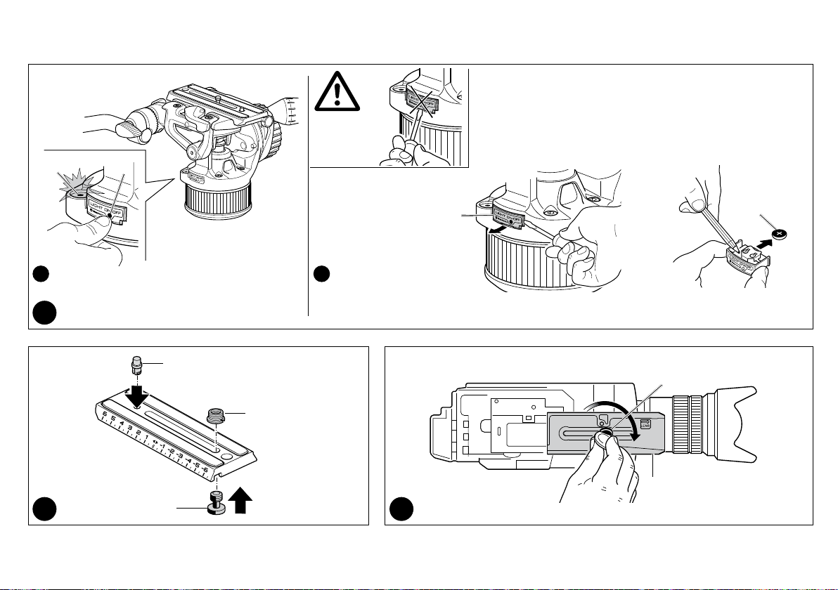
FITTING THE QUICK RELEASE PLATE TO A CAMCORDER &
The quick release plate (fig. 5) has a 1/4" camera screw "S", a 3/8" adapter "Z" to
mount on the screw "S" and an anti-rotation pin "G". All are supplied unmounted.
Check the size of the attachment hole on your camcorder, and select the correct screw
"Z" or "S" to fit to the quick release plate (fig. 5).
If the camcorder also has an anti-rotation hole, insert the anti-rotation pin "G" into the
3
4
5 6
8
Page 11
GB
plate as shown in figure 5. Align the camera on the plate "L" ensuring the pin "G" is
correctly inserted into the camera before fastening the plate.
Fix the camcorder onto the plate "L" (fig. 6) by tightening screw "Z" or "S" into
the threaded hole in the camcorder. You can use a coin to tighten the screw, but
WITHOUT APPLYING FORCE.
If the camcorder does not have an anti-rotation hole, align the camcorder lens with the
arrow marked "LENS" on the underside of camera plate "L" before tightening fully.
ATTACHING THE CAMCORDER TO THE HEAD
Before attaching the camcorder on the head, make sure the tripod is in a stable and
secure position and that the legs are locked.
Bring the head to 0 ° as in figure 7A (horizontal plate) and lock the tilt movement by
means of the brake "Q" .
Hold the camcorder and angle it so the plate "L" (fig. 7A) slots into the head, with the
long edge furthest from lever "M" dropping in first. Then push down so that the plate
drops in fully, and lever "M" clicks shut.
Hold the camera throughout this operation to prevent it from slipping backwards
and forwards.
Finding the right balance point for your camcorder:
- Level the head on the tripod using the spirit level "C" (fig. 4).
- Unlock the tilt brake “Q”
- Loosen the lever "M" (fig. 7B) and keep it pressed down as you slide the camcorder
until you reach the balance point in which the head remains level under the load of
the camcorder.
- With the camcorder at the balance point, lock plate "L" in position by locking knob
"M" as shown in figure 7C: the arrow must remain inside the LOCK rectangle.
NOTE:
Once the correct position has been found it can be memorised by taking note of plate
"L"’s position on the graded scale "R".
COUNTERBALANCING THE CAMERA ON THE HEAD
To balance the weight of your equipment, the head features a nitrogen piston
counterbalance system.
Please proceed as follows:
7
8
1. Make sure that you have unlocked the tilt brake "Q"
2. Pull out the counterbalance lever "N"
3. Turn counter-balance lever "N" counter clockwise until it reaches the end of the
counterbalance adjustment system run.
The "N" lever modifies the balanced load: it is a control system, not a lock. Once the
limit switch positions AA and BB have been reached (see figure 8C) with fluid
movement, do not force the lever's rotation.
Approximately 11 complete rotations of counterbalance lever "N" are required to
move from position "BB", equivalent to a counterbalanced load of 0 kg to position
"AA", equivalent to a balanced load of 8kg @55 c.o.g.
A higher number of rotations may compromise the counterbalance system's
performance or, in the worst cases, the product's safety.
4. Turn the tilt drag knob "P" clockwise.
With one hand on the pan bar, tilt the camcorder forwards and backwards: move
counterbalance lever "N" (lock/unlock) until the camera is locked into place for each tilt
angle.
REMOVING THE CAMCORDER FROM THE HEAD
Whenever the camcorder needs to be removed from the head, hold the
camcorder securely with one hand and press "M" to release the plate and camera
with the other hand, while keeping the "T" button pressed down.
The purpose of the "T" Security Button is to ensure that the video camera is not
released accidentally.
USE
10
For correct use, the head must be adequately levelled.
The head features 360° pan and vertical tilt (+90°/-70°) which are controlled using the
pan bar "A" (fig. 10).
- The pan movement can be locked using the knob "V" and has adjustable drag
control: friction is increased by turning gear "E".
- The tilt movement can be locked using the knob "Q" and has adjustable drag control:
friction is increased by turning gear "P".
Note:
The lever angle "V" can be positioned as required without affecting the lock itself. Pull
the lever outwards, turn as required and release: it will be set to the new position.
9
9
Page 12
GB
ATTACHING ACCESSORIES
The head has one 3/8" female thread "J" with an anti-rotation attachment which can
be used to attach accessories such as Manfrotto arms equipped with an anti-rotation
system.
Please note: fitting additional accessories may require adjusting the head’s balance
settings. An excessive load imbalance could compromise the tripod's stability and
invalidate the quality of the pan and tilt movements. In the worst cases, it could also
compromise product safety.
11
USAGE ADVICE
Prior to using the product, especially after an extended period of disuse, it is advisable
to restore proper lubrication of the gas spring gaskets. This is done by rotating the
head 3 times with the "A" lever through the entire TILT travel range.
Before use, please ensure that the central counterbalance system area is free of any
components that could affect the device’s correct operation (dust, sand, etc.).
Gas piston performance is affected by varying temperatures: to maintain correct
counterbalance with high temperature variations, the counterbalance knob must be
appropriately adjusted.
STORAGE
The product is NOT SUBJECT TO specific provisions for the carriage of dangerous
goods by road (ADR), rail (RID), inland waterway (ADN), sea (IMDG) and air (ICAO/
IATA).
We recommend transporting the equipment disassembled from the support and
mounted on the head.
When not in use, the product must be stored with its PAN & TILT brake and Drag
disengaged with the plate holder in a horizontal position.
Storage temperatures must range between -20°C and +60°C.
In case of extended periods of disuse, remove the battery from the light source (fig.4B).
MAINTENANCE
Clean the product only with non-aggressive detergents and soft cloths.
Periodically remove dust and sand from the locking screws and sliding parts. Do not
use sharp or metallic tools when carrying out cleaning procedures.
After a long period of disuse, if squeaking sounds are heard in the piston area, the
cylinder shaft should be lubricated with a PTFE spray (not included).
CAUTION
12
While the head is moving, do not put your hands or insert tools in the piston area
(fig. 12).
Keep the product away from children. Contains detachable parts that could be
swallowed.
PRECAUTIONS
• Do not tamper with, modify or disassemble the product or any of its parts to avoid
damaging its performance or safety.
• Do not use the product outside the defined scope.
• Using a damaged product, for example, due to accidental knocks or falls, may
compromise its operation safety.
• In such cases, contact your reseller or the manufacturer directly via the Contact Us
section on manfrotto.com.
• Dry the product after use in damp conditions to avoid corrosion.
• Especially when using the product in the vicinity of a marine environment.
• The product is not designed to be used immersed in liquids.
• Avoid exposing the product to sunshine for long periods or leaving it inside a vehicle,
where high temperatures can be reached.
• Do not expose to direct heat sources that may cause temperatures to exceed the
maximum temperatures specified in the "Working Temperature" section.
ELECTRICAL PRECAUTION
Never use any battery, power supply or accessory that is not specified by this manual.
Only use CR1220-3V batteries.
DISCLAIMER
The information contained in this document is subject to change without notice.
When needed, please check for updates to this manual by visiting the Products section
on manfrotto.com or by requesting an updated copy in the Contact Us section.
Manfrotto assumes no liability whatsoever for any damage that may, directly or
indirectly, result to persons, things or animals as a consequence of failure to comply
with all the requirements specified in this document, (in particular with regard to
product installation, use and maintenance), as well as injury and damage deriving
from incorrect use or purposes that go beyond the normal operating conditions and
restrictions.
Any changes or modifications to the product not expressly approved by Manfrotto shall
automatically result in the exclusion of Manfrotto's liability.
10
Page 13
GB
INFORMATION FOR USERS
In accordance with Article 10 of Directive 2012/19/UE of the 04/07/2012
concerning Waste Electrical and Electronic Equipment (WEEE).
The above symbol, also present on equipment, indicates that, at such time as
the user should decide to dispose of the equipment, it must NOT be disposed of as
unsorted municipal waste, but must be collected separately. The same applies to all
components of the equipment and any recharge or refill elements that the product may
comprise.
For information on the waste collection systems suitable for this equipment, contact
the seller or any authorised member of the National Registers in EU countries.
Household (or similar) waste may be disposed of via standard municipal differentiated
waste collection schemes.
If you purchase a new version of this model or similar equipment - or if your existing
equipment measures less than 25 cm - you may return the items you no longer require
to your retailer who will take care of contacting the company or organization handling
the proper collection and management of used equipment.
Correct separate collection and specific treatment of WEEE are necessary to avoid
potential damage to human health and the environment, and favour the recycling and
recovery of component materials.
Improper or illegal disposal of this product by the user will result in punishments or
fines being applied in accordance with national Decrees based on Directive 91/156/EC
and 2008/98/EC.
DECLARATION REGARDING PRESSURE RISK ASSESSMENT
The Nitrotech series heads include a gas spring used in their counterbalance system.
This component is designed and built following a high-quality engineering procedure;
it complies with European PED Directive 2014/68/EU Article 4, paragraph 3 and is not
subject to CE marking.
TECHNICAL PRODUCT SHEET
Counterbalanced Weight:
C.O.\G. Min. Max.
55 mm 0 8 kg / 17.6 lbs
75 mm 6,8 kg / 15 lbs
100 mm 5,7 kg / 12.6 lbs
Max Gas Pressure: 88bar @20°C
Illuminated Bubble Battery: NO. CR1220-3V
Degree of product protection: IP5X
Weight produced with drive lever: 2,2 kg / 4.85 lbs
Thank you for purchasing a Manfrotto product.
Manfrotto products are warranted to be fit for the purpose for which they have been
designed, and to be free from defects in materials and workmanship. This guarantee
does not cover the product against subsequent damage or misuse. The period of
validity of the Standard Limited Warranty is defined by the law in force in the country,
state or region where the product is sold. Please retain your receipt as proof of
purchase to repair your product under warranty.
How to get an extra warranty coverage
Beyond the standard compulsory coverage outlined above, this product is eligible
for a warranty extension valid up to 5 years from the date of purchase. The Limited
Conventional Warranty Extension does not affect the standard compulsory coverage.
To take advantage of the warranty extension scheme, you must register your purchase
at www.manfrotto.com/warranty.
11
Page 14
I
INTRODUZIONE
Ideata per videocamere digitali con lenti intercambiabili, ENG e DSLR di peso fino a
8kg (17.6 lbs) - dichiarato a 20°C e 55mm C.o.g.
Per utilizzi diversi da quello previsto al fine di garantire il corretto funzionamento e la
sicurezza durante l’utilizzo si prega di contattare il rivenditore o direttamente la casa
madre collegandosi al sito manfrotto.com nell’area Contact us.
Il prodotto è destinato ad un utilizzo professionale.
CARATTERISTICHE
• Piastra rapida scorrevole per bilanciare la videocamera
• Vite da 1/4" W e adattatore da 3/8" W per qualsiasi tipo di videocamera
• Attacco femmina da 3/8" per treppiede o per fissaggio semisfera
• Regolazione del frizionamento della panoramica e dell’inclinazione
• Leva panoramica posizionabile su ambo i lati della testa
• Livella a bolla (illuminata) per livellamento di precisione
• Sistema di controbilanciamento estremamente preciso e continuo
TEMPERATURE DI LAVORO
Temperatura di lavoro tra -15°C e +50°C.
Temperatura di stoccaggio tra -20°C e +60°C.
PREPARAZIONE E
Montare la batteria (fig. 1)
La testa è fornita con batteria "K" e portabatteria "X" smontati.
Montare la batteria nel porta batteria come mostra in figura 1.
Montare il porta batteria spingendolo nella sua sede della testa.
Montaggio leva di comando (fig. 2)
La testa è fornita completa di leva di comando "A" e di una rosetta dentellata di
protezione "U" entrambe non assemblate sul prodotto.
Una volta scelto su quale lato si vuole utilizzare la leva di comando "A", fissare la
rosetta di protezione "U" tramite le viti inserite nella confezione, successivamente
fissare la leva di comando sulla rosetta dentellata avvitando la manopola "D".
La rosetta "U" è dentellata per consentire la rotazione e il posizionamento della leva di
comando con angolazioni intervallate di 10°, evitandone lo spostamento accidentale.
Assicurarsi che la manopola "D" sia ben chiusa e che tra la dentatura della rosetta
"U" e quella del manicotto della barra di azionamento "A" non vi sia gioco per non
compromettere la continuità nei movimenti durante le riprese
1 2
MONTAGGIO DELLA TESTA
3A - Montare la testa su treppiedi foto/video usando il foro filettato "F" da 3/8".
I dischi di ancoraggio dei treppiedi Manfrotto sono dotati di grano/i "W" da stringere
contro la base della testa per garantirne un bloccaggio sicuro.
3B – Montare a testa su treppiedi con culla per semisfera da 75mm:
- montare la semisfera "Y" (opzionale) nella testa
- posizionare la testa all’interno della culla del treppiede
- avvitare l’impugnatura "H" (opzionale) contro la culla
3C – Montare la testa nella slider usando il foro filettato "F" da 3/8".
Non utilizzare viti che possano entrare sulla base della testa per una lunghezza
superiore a 8 mm perché questo potrebbe compromettere il funzionamento del
sistema di controbilanciamento o, nei casi peggiori, la sicurezza del prodotto.
LIVELLA A BOLLA
La livella a bolla "C" (fig. 4A) dispone di illuminazione che si accende premendo il
pulsante "B":
- premere il pulsante "B" per 1 secondo per illuminare la livella a bolla per 10 secondi
- premere il pulsante "B" per oltre 1 secondo per illuminare la livella a bolla per 60
secondi
Nota: la luce si spegne automaticamente dopo 10 o 60 secondi, ma è sempre possibile
riaccenderla manualmente premendo di nuovo il pulsante "B".
L’illuminazione dispone anche di un indicatore a LED per la carica della batteria: il LED
della batteria in prossimità del pulsante "B" si accende quando il livello di carica della
batteria scende.
Cambiare la batteria come indicato (fig. 4B):
- rimuovere il portabatteria "X" dalla testa con un cacciavite
- sostituire la batteria "K" (CR1220-3V)
Evitare di strofinare la livella a bolla: l’eventuale carica elettrostatica acquisita dalla
bolla potrebbe comprometterne temporaneamente la precisione.
4
FISSAGGIO DELLA PIASTRA RAPIDA AD UNA VIDEOCAMERA E
La piastra rapida (fig. 5) è dotata di una vite da 1/4" "S", un adattatore da 3/8" "Z" da
avvitare sulla vite "S" e un perno antirotazione "G" (tutti smontati).
Verificare la misura del foro sulla videocamera, quindi selezionare la vite corretta "S" o
3
5 6
12
Page 15
I
"Z" per fissare la piastra rapida (fig. 5).
Se la videocamera dispone di foro antirotazione, inserire il perno antirotazione "G" nella
piastra come mostrato in figura 5. Allineare la videocamera sulla piastra "L" verificando
che il perno "G" sia correttamente inserito nella videocamera prima di stringere la
piastra.
Fissare la videocamera sulla piastra "L" (fig. 6) serrando la vite "Z" o "S" nel foro
filettato della videocamera. Per stringere la vite si può usare una moneta, ma SENZA
APPLICARE FORZA ECCESSIVA.
Se la videocamera non dispone di foro antirotazione, allineare l’obiettivo della
videocamera con il simbolo a freccia "LENS" sul fondo della piastra "L" prima di
stringere a fondo.
MONTAGGIO DELLA VIDEOCAMERA SULLA TESTA
Prima di procedere al montaggio della videocamera sulla testa assicurarsi che il
treppiede sia in posizione stabile e sicura e che le gambe estensibili siano bloccate.
Portare la testa come in figura 7A a 0° (piastra orizzontale) e bloccare il movimento tilt
attraverso il freno "Q".
Posizionare la videocamera sulla testa, angolandola in modo che la piastra "L" (fig. 7A)
si inserisca nella testa, facendo entrare prima il lato lungo più lontano dalla leva "M".
Quindi spingere a fondo in modo che la piastra entri del tutto e la leva "M" scatti
in posizione di blocco. Durante questa operazione tenere la videocamera per
evitare cadute accidentali.
Trovare il bilanciamento della videocamera:
- livellare la testa utilizzando la livella a bolla "C" (fig. 4)
- allentare la leva "M" (fig. 7B) e tenendola premuta, fare scorrere la videocamera
avanti e indietro fino a trovare la posizione nella quale la testa rimane ferma con la
videocamera livellata
- bloccare la piastra "L" in posizione tramite leva "M" come mostrato in figura 7C: la
freccia deve stare all’interno della scritta "LOCK"
NOTA:
È possibile memorizzare la posizione di bilanciamento, facendo riferimento alla scala
graduata della piastra "L" nell’indice "R".
7
CONTROBILANCIAMENTO DELLA CAMERA SULLA TESTA
Per poter bilanciare il peso del vostro equipaggiamento, la testa è dotata di un sistema
di controbilanciamento con pistone ad azoto.
Procedere come segue:
1. Assicurarsi di aver sbloccato il freno del livellamento "Q"
2. Estrarre la leva di contro-bilanciamento "N".
3. Ruotare la leva del contro-bilanciamento "N" in senso anti orario fino ad arrivare alla
fine della corsa del sistema di regolazione del contro bilanciamento La leva "N" va a
modificare il carico bilanciato: è una regolazione non un bloccaggio; quindi arrivati ai
finecorsa posizione AA e BB (vedi fig. 8C) con movimento fluido, non forzare la
rotazione delle leva. Sono necessarie circa 11 rotazioni complete della leva di contro
bilanciamento "N" per passare dalla posizione "BB" corrispondente al carico
controbilanciato di 0 kg alla posizione "AA" corrispondente al carico bilanciato di
8kg@55 c.o.g.
Un numero superiore di rotazioni potrebbe compromettere il funzionamento del
sistema di controbilanciamento o, nei casi peggiori, la sicurezza del prodotto.
4. Ruotare in senso orario la manopola di frizionamento del tilt "P".
Con una mano sulla leva di comando, inclinare in avanti ed indietro la videocamera:
agire sulla leva del controbilanciamento "N" (sblocco e blocco) finché la videocamera
rimane bloccata in posizione per ogni angolo di inclinazione.
RIMOZIONE DELLA VIDEOCAMERA DALLA TESTA
Per rimuovere la videocamera dalla testa, reggere saldamente la videocamera con
una mano mentre con l’altra mano, tenendo premuto il pulsante di sicurezza "T"
premere la leva "M" mentre si estrae la videocamera dalla testa.
Il pulsante di sicurezza "T" ha lo scopo di assicurare che lo sgancio della videocamera
non avvenga accidentalmente
USO DELLA TESTA
Per un corretto uso la testa deve essere adeguatamente livellata.
I due movimenti Panoramico a 360° e di Tilt (+90°/-70°) della testa sono entrambi
controllati dalla leva di comando "A" (fig. 10).
- Il movimento panoramico è dotato di bloccaggio mediante la levetta "V", e di
manopola di regolazione del frizionamento "E": avvitandola si incrementa il
frizionamento.
10
8
9
13
Page 16

I
- Il movimento verticale è dotato di bloccaggio mediante il freno "Q" e di manopola di
regolazione del frizionamento "P": avvitandola si incrementa il frizionamento.
Nota: la posizione della leva a ripresa "V" può essere variata in qualsiasi momento
per maggior comodità di presa e utilizzo, senza influire sul blocco stesso. Tirare la
leva verso l’esterno, effettuare la rotazione voluta e rilasciare la leva, la quale rientrerà
automaticamente nella sede.
ATTACCHI PER ACCESSORI
La testa è provvista di un aggancio con foro filettato 3/8" con attacco anti-rotazione "J"
per il fissaggio di accessori (per esempio i braccetti Manfrotto equipaggiati con sistema
anti rotazione).
Nota: l’aggiunta di accessori potrebbe richiedere un aggiustamento del bilanciamento
della testa. Uno sbilanciamento eccessivo del carico potrebbe compromettere la
stabilità del treppiede ed inficiare la qualità dei movimenti panoramico e tilt. Nei casi
peggiori, potrebbe anche compromettere la sicurezza del prodotto.
11
SUGGERIMENTI D’USO
Prima di utilizzare il prodotto, in particolare dopo un periodo di inattività prolungato, si
consiglia di ripristinare la corretta lubrificazione delle guarnizioni della molla a gas ruotando 3 volte, tramite la leva di azionamento "A" la testa per tutta l’escursione del TILT.
Prima dell'uso, assicurarsi che la zona centrale del sistema di controbilanciamento
sia priva di componenti che potrebbero influenzare il corretto funzionamento del
dispositivo (polvere, sabbia, ecc.).
Le prestazioni del pistone a gas possono variare in base alla temperatura: per
ottimizzare il sistema di controbilanciamento con variazioni di temperatura elevate,
regolare la manopola di controbilanciamento in modo appropriato.
TRASPORTO E CONSERVAZIONE
Al prodotto NON SONO APPLICABILI disposizioni specifiche per il trasporto di merci
pericolose su strada (ADR), su ferrovia (RID), per vie navigabili interne (ADN), per mare
(IMDG) ed aereo (ICAO/IATA).
Raccomandiamo di smontare l’attrezzatura, montata sulla testa, dal supporto in caso
di trasporto.
Quando non in uso, il prodotto deve essere conservato con il freno del movimento
panoramico e di inclinazione sbloccate con il portapiastra in posizione orizzontale.
La temperatura di conservazione deve essere compresa tra -20 ° C e + 60 ° C.
In caso di lunghi periodi di inattività togliere la batteria dall’illuminatore (fig. 4B).
MANUTENZIONE
Per la pulizia utilizzare esclusivamente detergenti poco aggressivi e panni morbidi.
Rimuovere periodicamente polvere e sabbia dalle viti di bloccaggio e dalle parti
scorrevoli.
Non utilizzare utensili metallici o appuntiti durante le operazioni di pulizia.
In seguito ad un prolungato periodo di inattività, se si sentono dei cigolii nella zona del
pistone, è opportuno lubrificare lo stelo del cilindro con uno spray PTFE (non incluso).
ATTENZIONE
Mentre la testa è in movimento, non mettere mani o oggetti nell'area del pistone
(fig. 12).
Tenere lontano il prodotto dalla portata dei bambini. Contiene parti staccabili che
potrebbero essere ingoiate.
12
PRECAUZIONI
• Non manomettere, modificare o smontare il prodotto o parte di esso per non
comprometterne il funzionamento o la sicurezza del prodotto.
• Non utilizzare il prodotto al di fuori dei limiti definiti.
• L’utilizzo di un prodotto danneggiato per esempio a causa di urti o cadute accidentali
può comprometterne la sicurezza di utilizzo.
• In questi casi contattare il rivenditore o direttamente la casa madre collegandosi al
sito manfrotto.com nell’area Contact us.
• Asciugare il prodotto dopo l’utilizzo in condizioni umide per evitare l’innesco di
fenomeni di corrosione
• In particolare nel caso di utilizzo in prossimità di ambiente marino.
• Il prodotto non è progettato per essere utilizzato immerso nei liquidi.
• Evitare di lasciare il prodotto esposto al sole per lunghi periodi o all’interno dell’auto
dove si possono raggiungere temperature molto elevate.
• Non esporre a fonti di calore dirette che possano portare la temperatura al di sopra
delle temperature max previste nel paragrafo "Temperature di Lavoro".
PRECAUZIONI ELETTRICHE
Non utilizzare batterie, fonti di alimentazione o accessori non specificati nel presente
manuale. Utilizzare unicamente batterie CR1220-3V.
ESCLUSIONE DI RESPONSABILITÀ
Le informazioni riportate in questo documento sono soggette a variazioni senza preavviso.
14
Page 17

I
In caso di necessità, si invita a verificare la presenza di aggiornamenti del presente
manuale collegandosi al sito manfrotto.com nell’area Products o richiedendo l’invio di
una copia aggiornata nell’area Contact us.
Manfrotto declina ogni responsabilità per eventuali danni che possano, direttamente
o indirettamente, derivare a persone, cose o animali, in conseguenza della mancata
osservanza di tutte le indicazioni presenti in questo documento, (in particolare per
quanto riguarda installazione, uso e manutenzione del prodotto), nonché lesioni e danni
derivanti da un utilizzo o impiego non corretti che superino i normali limiti operativi.
Qualunque variazione o modifica apportata al prodotto senza espressa approvazione di
Manfrotto comporta l’automatica esclusione di responsabilità di Manfrotto.
INFORMAZIONE AGLI UTENTI
Ai sensi dell’art. 10 della Direttiva 2012/19/UE del 04/07/2012 sui rifiuti da
apparecchiature elettriche ed elettroniche (RAEE).
Il simbolo sopra riportato, presente anche sull’apparecchiatura, indica che essa
deve essere oggetto di raccolta separata nel momento in cui l’utilizzatore decide
di disfarsene (inclusi tutti componenti, i sotto-insiemi e i materiali di consumo che sono
parte integrante del prodotto).
Per l’indicazione sui sistemi di raccolta di detti apparecchi vi preghiamo di contattare
il Rivenditore o altro soggetto inscritto nei vari Registri Nazionali per gli altri Paesi
dell’Unione Europea. Il rifiuto originato da nucleo domestico (o di origine analoga) può
essere conferito a sistemi di raccolta differenziata dei rifiuti urbani.
All’atto dell’acquisto di una nuova apparecchiatura o, senza obbligo di un acquisto
nuovo, per le apparecchiature con dimensioni inferiori ai 25 cm, è possibile
riconsegnare al rivenditore il vecchio apparecchio. Il rivenditore si farà poi carico di
contattare il soggetto responsabile del ritiro dell’apparecchiatura.
L’adeguata raccolta separata dell’apparecchio dismesso e l’avvio alle successive
operazioni di trattamento, recupero e smaltimento ambientalmente compatibile,
consente di evitare potenziali effetti negativi sull’ambiente e sulla salute umana, e
favorisce il riciclaggio ed il recupero dei materiali componenti.
Lo smaltimento abusivo del prodotto da parte dell’utente comporta l’applicazione delle
sanzioni previste dai recepimenti nazionali delle Direttive 91/156/CE e 2008/98/CE.
DICHIARAZIONE RIGUARDANTE I RISCHI CONNESSI AL RECIPIENTE
SOTTO PRESSIONE
Le teste video della serie Nitrotech utilizzano, per la realizzazione del dispositivo di
contro-bilanciamento, una molla a gas; questo componente è progettato e fabbricato
secondo una corretta prassi costruttiva, è conforme alla direttiva comunitaria PED
2014/68/EU Articolo 4 comma 3 e non soggetto a marcatura CE.
SCHEDA TECNICA DI PRODOTTO
Carico contro-bilanciato:
C.O.\G. Min. Max.
55 mm 0 8 kg / 17.6 lbs
75 mm 6,8 kg / 15 lbs
100 mm 5,7 kg / 12.6 lbs
Pressione max Molla a Gas: 88bar@20°C
Batteria bolla illuminata: NO. CR1220-3V
Grado di protezione prodotto: IP5X
Peso prodotto con leva di azionamento: 2,2 kg / 4.85 lbs
Vi ringraziamo per l’acquisto di un prodotto Manfrotto.
Manfrotto garantisce che i propri prodotti siano idonei allo scopo per il quale sono stati
progettati ed esenti da difetti nei materiali e nelle lavorazioni. La presente garanzia non
copre il prodotto contro danneggiamenti o uso improprio. Il periodo di validità della
Garanzia Standard è definito dalla legislazione vigente nel paese, stato o regione nel
quale il prodotto viene venduto. Vi preghiamo di conservare una copia della prova
d’acquisto del vostro prodotto, poiché vi verrà richiesta in caso di riparazione.
Come estendere la copertura di garanzia
In aggiunta alla copertura standard obbligatoria sopra indicata, Manfrotto offre su
questo prodotto un’estensione di garanzia valida fino a 5 anni dalla data dell’acquisto
del prodotto. L’estensione di garanzia non influisce sulla copertura standard
obbligatoria. Per usufruire dell’estensione di garanzia è richiesta la registrazione del
vostro acquisto sul sito www.manfrotto.com/warranty.
15
Page 18

D
EINLEITUNG
Geeignet für ENG-Camcorder und Camcorder mit Wechselobjektiven oder DSLRKameras mit einem Gewicht von bis zu 8 kg. Angegeben bei 20 °C und einem
Schwerpunkt von 55 mm.
Zur Sicherung der ordnungsgemäßen Ausführung und zum Ihrem Schutz kontaktieren
Sie bitte, für andere Anwendungen als die dafür vorgesehenen, Ihren Verkäufer oder
den Hersteller direkt unter der Verwendung des Kontaktformulars auf manfrotto.com.
Das Produkt ist für den professionellen Gebrauch bestimmt.
WESENTLICHE FEATURES
• Schnellwechsel-Gleitplatte zum Ausbalancieren des Camcorders
• 1/4 Zoll Kameraschraube "S" und 3/8 Adapter "Z" für alle Kameraarten
• 3/8" Stativanschluss-Gewinde / Befestigung für Halbschale
• Fluidsteuerung für SCHWENK- und NEIGEACHSE
• Schwenkarm kann rechts oder links am Kopfes befestigt werden
• Nivellierlibelle (mit Hintergrundbeleuchtung) zur exakten Ausrichtung
• Äußerst präzises, stufenloses Gegengewichtssystem
TEMPERATURBEREICH
Betriebstemperatur zwischen -15 °C und +50 °C.
Lagertemperatur zwischen -20 °C und +60 °C.
AUFBAU UND
Einlegen der Batterie (Abb. 1):
im Lieferumfang ist eine Batterie "K" und ein Batteriehalter "X" (für die Nivellierlibelle)
enthalten.
Legen Sie die Batterie wie in Abbildung 1 gezeigt in den "Batteriehalter" ein.
Schieben Sie den "Batteriehalter" in den Kopf ein.
Befestigung des Schwenkarms (Abb. 2)
Der im Lieferumfang enthaltene Schwenkarm "A" und die gezackten Rosette "U"
sind nicht montiert. Nachdem Sie sich entschieden haben, an welcher Seite Sie den
Schwenkarm "A" montieren, sichern Sie die U-förmige Rosette mithilfe der Schrauben,
die im Lieferumfang enthaltenen sind. Dann sichern Sie den Schwenkarm an der
gezackten Rosette durch festziehen des Drehknopfs "D".
Die Rosette "U" hat Zähne, die es erlauben, den Schwenkarm zu drehen und in
10°-Schritten in jeder beliebigen Position zu positionieren. Ein Abrutschen oder
versehentliches Lockern wird dabei vermieden.
1 2
Stellen Sie sicher, dass der Drehknopf "D" fest verschlossen und kein Spielraum
zwischen Rosette "U" und der Hülse des Schwenkarms "A" ist, um die Kontinuität
der Bewegung während Ihrer Aufnahmen sicherzustellen.
BEFESTIGUNG DES KOPFES
3A - Montieren Sie den Kopf über das 3/8 Zoll Gewinde "F" auf dem Foto-/
Videostativ.
Die Auflagenteller von Manfrotto Stativen verfügt über eine Schraube "W", die von
unten gegen den Kopf geklemmt wird und eine noch sicherere Verriegelung garantiert.
3B - Befestigung des Kopfes auf Stativen mit 75 mm Halbschale:
- montieren Sie die Halbkugel "Y" (optional) am Kopf
- setzen Sie den Kopf so in die Halbschale des Stativs ein, dass die Gewindeschraube
unten aus der Halbschale herausragt
- schrauben Sie Griff "H" (optional) auf die Gewindeschraube, bis er an der Schale
anliegt.
3C - Montieren Sie den Kopf über das 3/8 Zoll Gewinde "F" auf dem Slider.
Nutzen Sie keine Schrauben länger als 8 Millimeter. Diese können in die Basis des
Videokopfes dringen und dort das Gegengewichtssystem beschädigen oder im
schlimmsten Falle die Sicherheit des Produktes beeinträchtigen.
NIVELLIERLIBELLE
Die Nivellierlibelle "C" (Abb. 4A) verfügt über eine Hintergrundbeleuchtung, die durch
Druck auf Taste "B" eingeschaltet werden kann:
- drücken Sie Taste "B" 1 Sekunde lang, um die Hintergrundbeleuchtung für 10
Sekunden zu aktivieren
- drücken Sie Taste "B" länger als 1 Sekunde, um die Hintergrundbeleuchtung für 60
Sekunden zu aktivieren
Anmerkung: das Licht schaltet sich nach 10 oder 60 Sekunden automatisch aus.
Drücken Sie Taste "B" erneut, um das Licht manuell auszuschalten.
Das Licht verfügt über eine LED-Batteriestandsanzeige: das rote LED-Batteriesymbol
neben der Taste "B" leuchtet auf, wenn die Batterie schwach wird.
Zum Austausch der Batterie (Abb. 4B):
- nehmen Sie den Batteriehalter "X" mithilfe eines Schraubenziehers vom Kopf ab
- ersetzen Sie die Batterie "K" durch eine CR1220-3V Batterie
4
3
16
Page 19

D
Kratzen Sie nicht an der Nivellierliebelle! Dadurch könnte diese elektrostatisch
aufgeladen werden und kurzfristig nicht mehr präzise anzeigen.
BEFESTIGUNG DER SCHNELLWECHSELPLATTE AN EINEM CAMCORDER
UND
5 6
Die Schnellwechselplatte (Abb. 5) verfügt über eine 1/4 Zoll Kameraschraube, einen 3/8
Zoll Adapter "Z"", der an Schraube "S" befestigt wird und einen Verdrehsicherungsstift
"G". Sie sind nicht vormontiert.
Überprüfen Sie die Größe des Gewindes an Ihrem Camcorder und wählen Sie die
passende Schraube "Z" oder "S" für die Schnellwechselplatte aus (Abb. 5).
Verfügt der Camcorder über eine Bohrung für einen Verdrehsicherungsstift, setzen Sie
den Verdrehsicherungsstift "G" wie in Abbildung 5 gezeigt in die Schnellwechselplatte
ein. Richten Sie die Kamera auf der Platte "L" aus. Achten Sie darauf, dass der Stift
"G" richtig in der Bohrung sitzt, bevor Sie die Platte festziehen.
Befestigen Sie den Camcorder auf der Platte "L" (Abb. 6), indem Sie die Schraube "Z"
oder "S" in der Gewindebohrung des Camcorders festziehen. Verwenden Sie dazu
beispielsweise eine Münze, aber OHNE ÜBERMÄSSIGEN KRAFTAUFWAND.
Hat der Camcorder keinen Verdrehsicherungsstift, richten Sie das Objektiv des
Camcorders mit der Markierung "LENS" unterhalb der Kameraplatte "L" aus, bevor Sie
die Schraube festziehen.
BEFESTIGUNG DES CAMCORDERS AM KOPF
Stellen Sie sicher, dass sich das Stativ in einer stabilen und sicheren Position befindet
und die Beine verriegelt sind, bevor Sie den Camcorder am Videokopf befestigen.
Bewegen Sie den Kopf in die Position 0 ° wie im Bild 7A (horizontale Platte) und
sperren Sie die Neigebewegung durch betätigen der Bremse "Q".
Halten Sie den Camcorder so, dass die Platte "L" (Abb. A) in den Kopf greift. Setzen
Sie zunächst die Längsseite ein, die sich gegenüber von Hebel "M" befindet. Drücken
Sie sie dann nach unten, bis der Hebel "M" einrastet.
Halten Sie die Kamera dabei gut fest, um ein versehentliches Verrutschen zu
vermeiden.
Zum Ausbalancieren Ihres Camcorders:
- Richten Sie mithilfe der Nivellierlibelle "C" den Kopf auf dem Stativ aus (Abb. 4).
- Riegeln Sie die Bremse für die Neigung "Q"
7
- Lösen Sie den Hebel "M" (Abb. 7B) und halten Sie ihn gedrückt, während Sie den
Camcorder nach vorne oder hinten schieben, bis Sie die optimale Position gefunden
haben, an der der Camcorder auf dem Kopf nicht nach vorne oder hinten kippt.
- Verriegeln Sie in dieser Position die Platte "L" mithilfe des Verriegelungshebels "M"
(siehe Abbildung 7C): der Pfeil muss sich innerhalb es Rechtecks LOCK befinden.
HINWEIS:
Notieren Sie die eingestellte Position mithilfe der Skala "R" auf der Platte "L", um die
richtige Einstellung jederzeit ohne langes Ausprobieren wiederzufinden.
GEWICHTSAUSGLEICH DES CAMCORDERS AUF DEM KOPF
Der Kopf verfügt über ein Gegengewichtssystem (mit Stickstoffkolben) für den
Gewichtsausgleich Ihrer Ausrüstung.
Gehen Sie bitte wie folgt vor:
1. Stellen Sie sicher, dass die Bremse für die Neigung "Q" entriegelt ist
2. Ziehen Sie den Gegengewichtshebel "N" aus
3. Drehen Sie den Gegengewichtshebel "N" gegen den Uhrzeigersinn, bis Sie das Ende
des Gegengewichtssystems erreicht haben (Abb. 8C Position BB). Der
Gegengewichtshebel "N" modifiziert die Ausgleichskraft des
Gegengewichtssystems. Es ist ein Kontrollsystem und keine Verriegelung.
Sobald die Begrenzungspositionen AA und BB durch eine flüssige Drehbewegung
erreicht sind, bewegen Sie den Gegengewichtshebel nicht mit Kraft weiter. Ungefähr
11 vollständige Umdrehungen des Gegengewichtshebels "N" sind notwendig um
von Position "BB" entsprechend des Gegengewichtes von 0 kg in die Position "AA"
entsprechend des Gegengewichtes von 8 kg bei Schwerpunkt +55 mm.
Eine höhere Anzahl an Umdrehungen kann die Leistung des
Gegengewichtssystems beeinträchtigen und im schlimmsten Fall die
Produktsicherheit gefährden.
4. Drehen Sie den Verriegelungsknopf im Uhrzeigersinn, bis die Kamera in jeder
Neigeposition balanciert ist
Halten Sie mit einer Hand den Schwenkarm fest und neigen Sie den Camcorder nach
vorne und nach hinten: bewegen Sie den Gegengewichtshebel "N" (verriegeln, lösen),
bis die Kamera bei jedem Neigungswinkel einrastet.
8
17
Page 20

D
ABNAHME DES CAMCORDERS VOM KOPF
Um den Camcorder vom Kopf abzunehmen, halten Sie ihn mit einer Hand fest
und drücken Sie mit der anderen Hand gleichzeitig "M" und Taste "T", um Platte
und Camcorder freizugeben.
Der Einsatzzweck der Taste "T" Sicherheitsknopfes ist es, Platte und Camcorder nicht
versehentlich freizugeben.
GEBRAUCH
Für eine korrekte Verwendung muss der Kopf richtig nivelliert sein.
Der Kopf erlaubt Schwenkbewegungen um 360° sowie Neigebewegungen um +90°/70°, die über den Schwenkarm "A" kontrolliert werden.
- Die Schwenkbewegung kann über Knopf "V" gesperrt werden. Die Drehvorrichtung
"E" ermöglicht die Erhöhung der Friktion.
- Die Neigebewegung kann über Knopf "Q" gesperrt werden. Die Drehvorrichtung "P"
ermöglicht die Erhöhung der Friktion.
Hinweis: Der Winkel des Hebels "V" kann ohne Einfluss auf die Klemmwirkung verstellt
werden. Ziehen Sie den Hebel hierzu nach außen, drehen Sie ihn wie gewünscht, und
geben Sie ihn frei. Er rastet in der neuen Stellung ein.
BEFESTIGUNG VON ZUBEHÖR
Der Kopf verfügt über ein 3/8" Innengewinde "J", an dem Zubehör, ausgestattet mit
dem Anti-Rotation-System, wie z.B. ein Manfrotto Arm 244 MINI/MICRO befestigt
werden kann. Bitte beachten Sie, dass der Knopf nach der Befestigung von Zubehör
eventuell neu ausbalanciert werden muss. Eine übermäßige Traglast kann die Stabilität
des Statives sowie Schwenk- und Neigebewegungen beeinträchtigen. Im schlimmsten
Fall ist die Produktsicherheit gefährdet.
10
11
9
EMPFEHLUNGEN ZUR VERWENDUNG
Bevor Sie das Produkt nutzen speziell, wenn das Produkt über einen längeren
Zeitraum nicht verwendet wurde, ist die ausreichende Schmierung des GasfederDichtungsringes wiederherzustellen. Dazu den Kopf drei Mal mithilfe des Schwenkarms
"A" im kompletten Neigebereich bewegen.
Überprüfen Sie vor der Verwendung, ob der Bereich um das
Gegengewichtsausgleichssystem frei von Teilen ist, die eine korrekte Funktion
beeinträchtigen könnten (Staub, Sand, usw.).
Die Leistung des Gaskolbens kann durch Temperaturschwankungen negativ
beeinflusst werden. Bei hohen Temperaturschwankungen ist es daher erforderlich, die
Gegengewichtseinstellung entsprechend anzupassen.
LAGERUNG
Das Produkt ist kein Bestandteil spezieller Transport Bestimmungen für Gefahrgüter
für den Landtransport (ADR), Schienenverkehr (RID), Binnenschifftransport (ADN),
Seeschifftransport (IMDG) oder Lufttransport (ICAO/IATA).
Es wird empfohlen, das Gerät vor dem Transport vom Stativ zu nehmen. Zur Lagerung
des Produktes sind die Verriegelungsknöpfe für Schwenk- und Neigebewegungen
sowie für die Friktion zu lösen.
Die Lagertemperatur muss zwischen -20°C und +60°C liegen.
Wird das Produkt über einen längeren Zeitraum nicht verwendet, entfernen Sie bitte die
Batterie der Lichtquelle (Abb. 4B).
WARTUNG
Reinigen Sie das Produkt ausschließlich mit nicht aggressiven Reinigungsmitteln und
einem weichen Tuch.
Entfernen Sie gelegentlich Staub und Sand von den beweglichen Produktteilen.
Nutzen Sie keine metallischen oder scharfen Gegenstände zur Reinigung.
Wird das Produkt über einen längeren Zeitraum nicht verwendet, sind eventuell
Quietschgeräusche an der Gaskolbenstange zu hören. Schmieren Sie in diesen Fall
bitte die Kolbenstange mit einem PTFE-Spray (nicht enthalten) ein.
WARNUNG
12
Während der Kopf bewegt wird, dürfen sich keine Finger und Werkzeuge im
Kolbenbereich befinden (Abb. 12).
Nicht in Reichweite von Kindern aufbewahren. Nicht verschlucken.
VORSICHTSMASSNAHMEN
• Modifizieren oder Manipulieren Sie das Produkt oder einzelne Bestandteile nicht, um
die Leistung und Sicherheit des Produktes nicht zu beeinträchtigen.
• Verwenden Sie das Produkt nicht außerhalb des definierten Einsatzbereiches.
• Die Verwendung eines beschädigten Produktes, zum Beispiel durch versehentliche
Stöße oder Stütze, beeinträchtigt womöglich die Betriebssicherheit.
• In diesem Fall kontaktieren Sie bitte den Verkäufer oder den Hersteller direkt unter
Verwendung des Kontaktformulars auf manfrotto.com.
• Trocknen Sie das Produkt nach Verwendung in feuchter Umgebung oder bei Regen
ab um Korrasion zu vermeiden, besonders, wenn Sie das Produkt im Salzwasser
Umfeld verwenden.
18
Page 21

D
• Das Produkt ist nicht dafür ausgelegt in Flüssigkeit eingetaucht zu werden.
• Lassen Sie das Produkt nicht längere Zeit in der Sonne stehen und vermeiden Sie
hohe Temperaturen über einen längeren Zeitraum (z.B. im Auto auf der Hutablage
oder hinter Glasscheiben).
• Setzen Sie das Produkt keiner Wärmequelle aus, die die maximale
Betriebstemperatur, spezifiziert im Abschnitt "Arbeitstemperatur", übersteigt.
ELEKTRISCHE VORSICHTSMASSNAHMEN
Benutzen Sie niemals aufladbare Batterien, Stromversorgungen oder andere
Zubehörteile, welche nicht in dieser Bedienungsanleitung angegeben sind. Nur mit
CR1220-3V Batterien zu verwenden.
RECHTLICHE HINWEISE
Die in diesem Dokument enthaltenen Informationen können ohne Vorankündigung
geändert werden.
Für Änderungen der Bedienungsanleitung prüfen Sie bitte den Produktbereich auf
manfrotto.com oder fordern eine aktualisierte Version über das Kontaktformular
an. Manfrotto übernimmt keinerlei Haftung für jegliche Schäden, die infolge
unsachgemäßer Handhabung (insbesondere in Bezug auf Produktinstallation,
Gebrauch und Wartung) direkt oder indirekt Personen, Tiere oder Dingen zugefügt
werden können sowie für Verletzungen und Schäden, die durch unsachgemäße
Benutzung oder Zwecke entstehen, die über die normalen Betriebsbedingungen und
Einschränkungen hinausgehen.
Jegliche Änderungen oder Modifikationen, die nicht von Manfrotto genehmig wurden,
kann die Berechtigung des Benutzers zum Betrieb dieses Geräts aufheben.
VERBRAUCHERHINWEISE
Betrifft Paragraph 10 der Direktive 2012/19/UE vom 04.07.2012 über die
Entsorgung elektrischer und elektronischer Geräte (WEEE).
Das obenstehende Symbol, das sich auch auf dem Gerät findet, sagt aus, dass
das Gerät nach dem 13.8.2005 auf den Markt gekommen ist und damit der
Regelung unterliegt, der zufolge der Endverbraucher für seine Entsorgung
verantwortlich ist. Es darf nicht mit dem normalen Hausmüll entsorgt werden, sondern
ausschließlich als Sondermüll. Dasselbe gilt für sämtliche Bauteile des Geräts sowie
eventuell vorhandene Nachfüll- oder Auflade-Elemente.
Informationen über die für dieses Gerät geeignete Entsorgung sind erhältlich vom
Verkäufer oder jedem autorisierten Mietglied des Nationalregisters in Ländern der
EU. Haushalts- (oder ähnlicher) Müll darf nach den Mülltrennungs-Vorschriften der
jeweiligen Gemeinde entsorgt werden.
Wird dieses oder ein ähnliches Gerät neu gekauft, oder wenn Ihr jetziges Gerät die
Größe von 25 cm unterschreitet, kann das alte Gerät an den Verkäufer zurückgegeben
werden, der sich seinerseits mit der zuständigen Firma oder Körperschaft in
Verbindung setzen wird, die für die Einsammlung und Verwertung gebrauchter Geräte
zuständig ist.
Mülltrennung und die korrekte Entsorgung von WEEE dienen dem Gesundheits- und
Umweltsschutz. Sie unterstützen das Recycling und die Wiederverwendung wertvoller
Rohmaterialien.
Unsachgemäße oder illegale Entsorgung dieses Produkts durch den Endverbraucher
wird gemäß dem nationalen Dekret auf Grundlage der Direktiven 91/156/EC und
2008/98/EC bestraft.
ERKLÄRUNG ZUR DRUCK- GEFÄHRDUNGSBEURTEILUNG
Die Nitrotech Videokopf Serie verwendet eine Gasfeder im Gegengewichtssystem.
Diese Komponente wird unter hohen Qualitätsstandards konzipiert und produziert und
entspricht der Europäischen PED Richtlinie 2014/68/EU Artikel 4, Paragraf 3 und ist
nicht Bestandteil der CE-Kennzeichnung.
19
Page 22

D
TECHNISCHES PRODUKT DATENBLATT
Maximales Gewicht:
C.O.\G. Kameraschwerpunkt Min. Max.
55 mm 0 8 kg / 17.6 lbs
75 mm 6,8 kg / 15 lbs
100 mm 5,7 kg / 12.6 lbs
Max Gasdruck: 88bar bei 20°C
Batterie beleuchtete Nivellierlibelle: NO. CR1220-3V
Produktschutz: IP5X
Gewicht mit Schwenkarm: 2,2kg / 4.85 lbs
Vielen Dank, dass Sie sich für ein Manfrotto Produkt entschieden haben.
Manfrottogarantiert,dass die Produkte fürden Zweck, für den sie entwickelt wurden,
geeignet und frei von Fehlern in Material und Verarbeitung sind. Diese Garantie deckt
das Produkt nicht bei Folgeschäden oder Missbrauch. Die Gültigkeitsdauer der
Standardgarantie wird durch das jeweilige geltende Recht des Landes,des States
oder der Region, in demdas Produkt verkauft wird, bestimmt. Bitte bewahren Sie den
Kassenbon als Kaufbeleg auf, damit Ihr Produkt im Rahmen der Garantie repariert
werden kann.
Wie Sie eine zusätzliche Garantie erhalten
Neben der oben beschriebenen Standardgarantie können Sie für dieses Produkt
eine zusätzliche Garantieerweiterung mit einer Gültigkeit von bis zu 5 Jahren ab
dem Kaufdatum erhalten. Die limitierte Garantieverlängerung (Limited Conventional
Warranty Extension) hat keine Auswirkung auf die obligatorische Standardgarantie. Um
die Vorteile der Garantieverlängerung nutzen zu können, müssen Sie Ihren Kauf auf
www.manfrotto.com/warranty registrieren.
20
Page 23

F
INTRODUCTION
Mise au point pour les caméras de reportage, les caméscopes avec optiques
interchangeables ou les Reflex jusqu’à 8kg. Efficacité totale pour des inclinaisons
jusqu’à 20° et un centre de gravité déporté jusqu’à 55mm.
Si vous souhaitez utiliser le produit à d'autres fins que celles prévues et afin de garantir
des performances adaptées et une sécurité maximale, veuillez contacter le revendeur
auprès duquel vous avez acheté le produit ou le fabricant depuis le Formulaire de
contact sur manfrotto.com. Ce produit a été conçu pour une utilisation professionnelle.
CARACTERISTIQUES CLES
• Plateau rapide long coulissant pour un équilibrage
• Pas de vis 1/4" "S" et adaptateur "Z" pour tous les types de caméras
• Fixation 3/8" pour trépied ou adaptateur demi-bol
• Ajustement de la friction du mouvement panoramique et de la bascule
• Levier ajustable en position droitier ou gaucher
• Niveau à bule rétroéclairé pour une mise à niveau rapide
• Système de contrebalancement continue pour une précision incroyable
ECHELLE DE TEMPERATURE
Températures d’utilisation entre -15°C et +50°C.
Températures de stockage entre -20°C et +60°C.
MISE EN PLACE ET
Installez la batterie (fig. 1)
La rotule est fournie avec une batterie "K" et un porte batterie "X" séparé (pour le
niveau à bulle).
Installez la batterie sur le support de batterie comme montré sur la figue 1.
Installez le support de batterie sur la rotule simplement en le poussant au travers de la
rotule.
Installation de la poignée de guidage (figure 2)
La rotule est fournie avec une poignée de guidage "A" et une rosette crantée "U". Ces
deux éléments sont livrés démontés de la rotule. Une fois que vous avez choisi de quel
côté vous souhaitez placer la poignée de guidage "A", fixez la rosette à l’aide des vis
fournies puis fixez la poignée de guidage sur la rosette en serrant le levier "D".
La rosette "U" possède des dents pour permettre au levier de guidage de pivoter et
d’être positionné à intervalles de 10°, empêchant ainsi les glissements.
1 2
Veillez à ce que le levier "D" soit bien verrouillé et à ce qu’il n’y ait pas de jeu entre
la rosette "U" et la poignée de guidage "A" pour assurer la fluidité de mouvements
lorsque vous filmez.
INSTALLATION DE LA ROTULE
3A – Installez la rotule sur un trépied photo/vidéo en utilisant le pas de vis femelle 3/8" "F".
Les plateaux supérieurs des trépieds Manfrotto sont équipés de vis "W" qui verrouillent
la rotule sur le trépied et sécurisent totalement les deux éléments.
3B – Installer la rotule sur des trépieds équipés d’un bol de 75mm de diamètre :
- Assemblez le demi-bol "Y" (en option) sur la rotule
- Placez la rotule sur le bol du trépied permettant ainsi à la vis longue de se retrouver
sous le bol
- Vissez la poignée grip "H" sur la vis male jusqu’au serrage complet sur le bol
3C – Assemblez la rotule sur le slider en utilisant le pas de vis femelle 3/8" "F".
Ne pas utiliser de vis qui peuvent entrer dans la base de la rotule de plus de
8mm, cela risque d’endommager le système de contrebalancement voire de
compromettre la sécurité du produit.
NIVEAU A BULLE
Le niveau à bulle "C" (fig. 4A) possède un rétro éclairage qui se déclenche en appuyant
sur le bouton "B" :
- Pressez le bouton "B" pendant une seconde pour allumer le niveau à bulle pendant
10 secondes
- Pressez le bouton "B" pendant plus d’une seconde pour allumer le niveau à bulle
pendant 60 secondes.
Remarque : La lumière s’éteint automatiquement au bout de 10 ou de 60 secondes.
Pour l’éteindre manuellement, pressez de nouveau le bouton "B".
La lumière possède un indicateur de batterie LED : Le symbole de la LED rouge à côté
du bouton "B" s’allume lorsque le niveau de batterie est bas.
Pour changer la batterie (fig. 4B) :
- Retirez le support de batterie "X" de la rotule avec un tournevis
- Remplacez la batterie "K" avec une batterie CR1220-3V
Evitez de frotter le niveau à bulle: l’électricité statique peut compromettre l’exactitude
du niveau à bulle de façon temporaire.
4
3
21
Page 24

F
POSITIONNER LE PLATEAU RAPIDE SUR UNE CAMERA &
Le plateau rapide (fig. 5) possède un pas de vis 1/4" "S", un adaptateur 3/8" "Z" à
monter sur la vis "S" et un ergot "G" anti rotation. Tous sont fournis non assemblés.
Vérifiez la taille du pas de vis sur votre caméra et sélectionnez la bonne taille de vis "Z"
ou "S" pour positionner le plateau rapide (fig. 5).
Si la caméra possède également un trou anti rotation, insérez l’ergot anti rotation G
sur le plateau comme montré sur la figure 5. Alignez la caméra sur le plateau "L", vous
assurant que l’ergot "G" est correctement inséré au travers de la caméra avant le
serrage du plateau rapide.
Fixez la caméra sur la plateau "L" (fig. 6) par le serrage de la vis "Z" ou "S". Vous
pouvez utiliser une pièce de monnaie pour serrer la vis mais sans appliquer TROP DE
FORCE.
Si la caméra n’a pas de trou anti rotation, alignez l’optique de celle-ci avec la flèche
"LENS" située sur le dessous du plateau rapide "L" avant le serrage.
POSITIONNER LA CAMERA SUR LA ROTULE
Avant de fixer la caméra sur la rotule, assurez-vous que le trépied est dans une position
stable et sécurisée et que les jambes sont bien verrouillées.
Positionnez la rotule sur 0° comme montré en figure 7A (à l’horizontale) et verrouillez le
mouvement de bascule à l’aide de la molette "Q".
Tenez la caméra et positionnez-la sur le coté de manière à ce que le plateau "L" (fig.
7A) voit la tranche opposée au levier "M" se positionner en premier sur la rotule. Puis
poussez le côté opposé du plateau vers le bas de manière à verrouiller le levier "M".
Maintenez la caméra pendant la durée de cette opération afin de prévenir à tous
risques de glissements avants ou arrières.
Trouvez le bon contrebalancement pour votre caméra :
- Faites la mise à niveau de la rotule en utilisant le niveau à bulle "C" (fig. 4)
- Déverrouillez la molette "Q".
- Maintenez desserré le levier "M" (fig. 7B) afin de vous permettre de faire glisser le
plateau long sur le rail et trouver le point d’équilibrage de la caméra.
- Une fois le point d’équilibrage trouvé, verrouillez le plateau "L" en utilisant le levier
"M" comme montré sur la figure 7C : la flèche doit revenir à l’intérieur du rectangle de
verrouillage.
7
5 6
Remarque : Une fois une point d’équilibrage trouvé, vous pouvez le mémoriser en
notant la position du plateau "L" sur l’échelle graduée "R".
EQUILIBRER LA CAMERA SUR LA ROTULE
Pour équilibrer le poids de votre équipement, la rotule possède un système de
contrebalancement avec un piston nitrogène.
L’ensemble doit suivre la procédure suivante :
1. Assurez-vous que vous avez bien déverrouillé la molette "Q".
2. Tirez la poignée de contrebalancement "N" pour la faire ressortir.
3. Tournez la poignée de contrebalancement "N" dans le sens contraire des aiguilles
d’une montre jusqu’à ce que le piston soit totalement sorti. La poignée "N" permet
de modifier le poids de contrebalancement: il s’agit d’un système de contrôle et non
de verrouillage. Une fois que vous avez atteint la position "AA" ou "BB" à l’aide des
mouvements fluides, ne forcez pas la rotation de la poignée. Il faut environ 11
rotations complètes de la poignée de contrebalancement "N" pour passer de la
position "BB" (qui correspond à 0kg de contrebalancement) à la position "AA" (qui
correspond à 8 kg de contrebalancement avec centre de gravité déporté jusqu’à
55mm).
Si vous réalisez des rotations supplémentaires, vous risquez d’endommager le
système de contrebalancement voire de compromettre la sécurité du produit.
4. Tournez la bague de friction "P" dans le sens des aiguilles d’une montre.
Avec une main sur le levier de guidage, faites agir le mouvement de bascule vertical
en avant et en arrière : bouger le levier "N" de contrebalancement (verrouillage/
déverrouillage) jusqu’à ce que la caméra soit verrouillée sur son angle de bascule.
RETIRER LA CAMERA DE LA ROTULE
A chaque fois que la caméra a besoin d’être retirée de la rotule, tenez la caméra
avec une main et pressez "M" afin de retirer le plateau et la caméra avec l’autre
main, tout en conservant le bouton "T" pressé vers le bas.
Le bouton de sécurité "T" permet d’éviter un retrait accidentel de la caméra.
8
9
22
Page 25

F
UTILISATION
Pour une utilisation correcte, la rotule doit être mise à niveau.
La rotule permet un mouvement panoramique à 360° et une bascule verticale de +90°/70° pouvant être contrôlé en utilisant le levier de guidage "A" (fig. 10).
- Le mouvement panoramique peut être verrouillé en utilisant le levier "V" et possède
une friction réglable : celle-ci se durcie en tournant la bague "E".
- Le mouvement de bascule vertical peut être verrouillé en utilisant le levier "Q" et
possède une friction réglable : celle-ci se durcie en tournant la bague "P".
Remarque :
Le levier de verrouillage "V" peut être ajusté sans modifier son serrage. Pour cela,
tirez sur le levier, tournez-le comme désiré puis relâchez le pour le verrouiller dans sa
nouvelle position.
ACCESSOIRES SATELLITES
La rotule est équipée d’un pas de vis femelle 3/8" "J" avec fonction anti-rotation qui
sert à fixer des accessoires comme un bras articulé Manfrotto avec système antirotation.
Remarque: Le fait de positionner des accessoires supplémentaires peut nécessiter
d’ajuster les réglages d’équilibrage de la rotule. Une charge non équilibrée et trop
élevée peut affecter la stabilité du trépied et compromettre la qualité du mouvement
panoramique et du mouvement de bascule. Pire encore, cela risque de compromettre
la sécurité du produit.
10
11
CONSEILS D’USAGE
Si vous n’avez pas utilisé le produit depuis une longue période, il est préférable de
réaliser une lubrification adaptée des joints du piston Nitrogen. Pour cela, faites
pivoter la rotule trois fois à l’aide de la poignée de guidage "A" sur toute l’amplitude du
mouvement de bascule.
Avant utilisation, assurez-vous que le système de contrebalancement n’est pas affecté
par un objet ou des impuretés qui pourrait altérer l’opération (poussière, sable, etc…)
La performance du piston à gaz peut être affecté par des variations de températures:
pour maintenir un parfait contre balancement avec des hautes variations de
températures, le levier de contrebalancement doit être ajusté en circonstance.
STOCKAGE
Le produit N’EST PAS SOUMIS aux dispositions spécifiques pour marchandises
dangereuses pour le transport terrestre (ADR), le transport ferroviaire (RID), le transport
fluvial (ADN), le transport par mer (IMDG) et le transport aérien (ICAO/IATA).
Nous vous recommandons de retirer le produit du support pour le transporter. Quand
vous n’utilisez pas le produit, veillez à le ranger après avoir desserré la friction et les
molettes du mouvement panoramique et du mouvement de bascule et placé le support
du plateau en position horizontale.
Température de stockage: entre -20°C et +60°C
Si vous n’utilisez pas le produit pour une longue période, retirez la batterie du niveau à
bulle rétroéclairé (figure 4B).
MAINTENANCE
Nettoyez le produit avec du détergent non agressif et un chiffon doux.
Retirez régulièrement la saleté et le sable des vis et des éléments coulissants.
N’utilisez pas d’objet pointu ou d’outil en métal quand vous nettoyez le produit. Suite à
une longue période d’inactivité, si des sons de grincement apparaissent, lubrifiez la tige
du piston avec un spray PTFE type WD40 (non inclus).
ATTENTION
12
Lorsque la rotule est en mouvement, ne placez pas vos mains ou des outils dans
la zone de mouvement du piston (figure 12).
Maintenez le produit hors de portée des enfants: ils pourraient avaler certains
éléments amovibles du produit.
23
Page 26

F
PRECAUTIONS
• N’essayez pas de modifier ou de démonter le produit ou l’un de ses composants,
cela risque d’affecter les performances et la sécurité du produit.
• N’utilisez pas le produit à d’autres fins que celles prévues.
• L’utilisation d’un produit qui a été endommagé, par des coups accidentels par
exemple, risque de compromettre la sécurité de la manipulation.
• Si votre produit a été endommagé, veuillez contacter le revendeur auprès duquel
vous avez acheté le produit ou le fabricant depuis le Formulaire de contact sur
manfrotto.com.
• Séchez le produit après utilisation dans un environnement humide afin d’éviter la
corrosion.
• Sécher le produit est particulièrement important après une utilisation à proximité d’un
milieu maritime.
• Le produit n’a pas été conçu pour résister à son immersion dans du liquide.
• Ne laissez pas le produit à l’exposition directe du soleil pendant une période
prolongée, comme dans une voiture garée en plein soleil, où une température très
élevée peut être atteinte.
• N’exposez pas directement le produit à des sources de chaleur qui risquent
d’entraîner une augmentation de la température supérieure aux températures
tolérées spécifiées dans la section "ECHELLE DE TEMPERATURE".
PRÉCAUTIONS ÉLECTRIQUES
Ne jamais utiliser de batterie, bloc d’alimentation ou accessoire non spécifié dans ce
manuel. N’utilisez que des batteries CR1220-3V.
AVIS DE NON-RESPONSABILITE
Les informations présentes dans ce document sont susceptibles d’être modifiées sans
avis préalable.
Si besoin est, veuillez consulter les mises à jour de ce manuel sur la page du produit
sur manfrotto.com ou en demandant la version actualisée via le Formulaire de contact
du site web. Manfrotto décline toute responsabilité concernant les dommages directs
ou indirects causés aux utilisateurs, aux objets ou aux animaux et dus au nonrespect des exigences exposées dans ce document (en particulier ce qui concerne
l’installation, l’utilisation et l’entretien du produit), ainsi que les dommages corporels
dus à une mauvaise utilisation du produit ou à une utilisation à d’autres fins que celles
prévues dans des conditions normales de manipulation.
Toute modification apportée au produit et non expressément approuvée par Manfrotto
exclue automatiquement la responsabilité de Manfrotto.
INFORMATION AUX UTILISATEURS
Conformément à l’article 10 de la Directive 2012/19/UE du 04/07/2012 relative
aux déchets d’équipements électriques et électroniques (DEEE).
Le symbole ci-dessus, qui apparaît sur les équipements concernés, indique que
ceux-ci ont été mis en vente après le 13/08/2005 et ne devront par conséquent
PAS être jetés avec les ordures ménagères mais faire l’objet d’une collecte sélective
lors de leur mise au rebut. Cette mesure s’étend également aux composants, matières
et énergie que ces équipements peuvent contenir.
Pour les informations relatives à la gestion des déchets de cet équipement, contactez
le revendeur auprès duquel vous avez acheté le produit ou une autorité compétente de
la gestion des déchets.
Si vous achetez une nouvelle version de ce modèle ou un équipement similaire - ou si
votre équipement actuel mesure moins de 25 cm - vous pouvez retourner le précédent
produit chez votre revendeur qui prendra soin de contacter l’entreprise ou l’organisme
responsable de la collecte et du traitement de ce type de déchets.
Une collecte et un traitement adaptés des DEEE sont indispensables pour éviter les
risques potentiels pour la santé et l’environnement et favoriser la récupération et la
valorisation des matériaux qui les composent.
Toute élimination incorrecte ou illégale du présent produit condamnera l’utilisateur
à une peine ou une amende conformément aux décrets nationaux appliquant les
Directives 91/156/CE et 2008/98/CE.
24
Page 27

F
DECLARATION SUR LA GESTION DU RISQUE LIE A LA PRESSION
Les rotules Nitrotech sont équipées d’un piston au gaz utilisé dans le système de
contrebalancement. Cet élément a été conçu et fabriqué dans le respect d’une
procédure de haute qualité: il répond aux normes du paragraphe 3 de l’article 4 de la
directive européenne PED 2014/68/EU et il n’est pas soumis à l’obligation de porter le
marquage "CE".
CARACTERISTIQUES TECHNIQUES
Poids contrebalancé:
C.O.\G. (déport du centre de gravité) Min. Max.
55 mm 0 8 kg / 17.6 lbs
75 mm 6,8 kg / 15 lbs
100 mm 5,7 kg / 12.6 lbs
Pression maximale du gaz : 88 bar @ 20°C
Référence batterie niveau à bulle rétroéclairé: CR1220-3V
Indice de protection du produit: IP5X
Poids avec la poignée de guidage: 2,2 kg
Merci d’avoir acheté un produit Manfrotto.
Les produits Manfrotto sont garantis pour un champ d’utilisation correspondant à
celui pour lequel ils ont été conçus, sans malfaçons humaines ou matérielles. Cette
garantie ne couvre pas le produit contre des dommages ou des mauvaises utilisations.
La période de validité de la Garantie Standard est définie par la loi en vigueur dans
le pays, l’état ou la région où le produit est vendu. Merci de conserver votre preuve
d’achat afin de pouvoir faire réparer votre produit sous garantie.
Comment obtenir une extension de garantie
Au-delà de la garantie de base décrite dans le paragraphe ci-dessus, le produit est
éligible à une extension de garantie pour un total de 5 ans à partir de sa date d’achat.
Cette Extension de Garantie n’affecte en aucun cas la couverture initiale de la Garantie
Standard. Afin de profiter de cette extension de garantie, vous devez enregistrer votre
produit sur : www.manfrotto.com/warranty.
25
Page 28

E
INTRODUCCIÓN
Diseñadas para videocámaras ENG y videocámaras de objetivos intercambiables o
DSLRs hasta 8 kg (17,6 lb). Declarado a 20°C y centro de gravedad a 55mm.
Para cualquier otro uso que no sea el previsto, para lograr unas prestaciones correctas
y garantizar la seguridad de uso, por favor contacte su distribuidor o fabricante
directamente a través de la sección de Contacte con nosotros en manfrotto.com.
El producto está indicado para un uso profesional.
PUNTOS CLAVE
• Zapata de liberación rápida deslizante para equilibrar la videocámara
• Rosca para cámara 1/4" "S" y adaptador 3/8’’ "Z" para toda clase de cámaras
• Rosca hembra 3/8” o para montaje del adaptador semiesfera
• Ajuste de la intensidad (freno) del movimiento de Paneo (PAN) e inclinación (TILT)
• La barra de paneo (Pan) se puede montar en ambos lados (derecha o izquierda)
• Nivel de burbuja (con iluminación posterior) para un nivelado más preciso
• Precisión increíble, sistema de contrabalance continuo
TEMPERATURA
Temperatura de trabajo entre -15°C y +50°C.
Temperatura de almacenamiento entre -20°C y +60°C.
MONTAJE Y
Montaje de la batería (fig. 1)
La rótula se entrega con una batería "K" y un soporte para batería "X" (para el nivel
de burbuja) desmontados. Monte la batería en el "soporte para batería" tal como
se muestra en la figura 1. Monte el "soporte para batería" en la rótula simplemente
colocándola en la ranura correspondiente.
1 2
Montaje de la palanca de control (fig. 2)
La rótula se entrega completa con palanca de control "A" y la roseta dentada "U".
Ninguna de ellas está montada en el producto. Una vez ha elegido el lado en el cual
desea montar la palanca de control "A", en primer lugar asegure la roseta dentada
en forma de U usando los tornillos incluidos en la caja del producto, y a continuación
asegure la palanca de control en la roseta apretando la palanca con rosca "D".
La roseta "U" está dentada para para permitir la rotación y posicionamiento de la
palanca de control en intervalos de 10 °, evitando el desplazamiento accidental.
Asegúrese que la palanca con rosca "D" esté firmemente cerrada y que no hay
juego entre la roseta "U" y la cubierta de la barra "A", de forma que la continuidad
de movimiento no tenga problemas durante la grabación.
MONTANDO LA RÓTULA
3A – Monte la rótula en el trípode de foto/vídeo usando la rosca hembra 3/8" "F".
La plataforma superior de los trípodes Manfrotto está equipada con tornillo(s) "W"
que se pueden pinzar contra la base de la rótula para asegurar un bloqueo seguro y
efectivo.
3B – Montura de la rótula en trípodes con soporte para semiesfera de diámetro
de 75mm:
- monte la semiesfera "Y" (accesorio opcional) en la rótula
- sitúe la rótula en el trípode de forma que la rosca macho sobresalga del soporte de
la semiesfera
- atornille la empuñadura "H" (opcional) en la rosca macho hasta que descanse contra
el soporte de la semiesfera
3C – Monte la rótula en el slider usando la rosca hembra 3/8" "F".
No use tornillos que puedan entrar en la base de la rótula más de 8 milímetros,
para no comprometer las prestaciones del sistema de contrabalanceo o, en casos
extremos, la seguridad del producto.
NIVEL DE BURBUJA PARA NIVELACIÓN
El nivel de burbuja "C" (fig. 4A) incorpora iluminación posterior que se puede activar
pulsando el botón "B":
- pulse el botón "B" durante 1 segundo y el nivel de burbuja se iluminará durante 10
segundos
- pulse el botón "B" durante más de 1 segundo para iluminar el nivel de burbuja
durante 60 segundos
Nota: la luz se apaga automáticamente tras 10 o 60 segundos. Para desconectarla
manualmente, pulsar el botón "B" de nuevo.
La luz posee también un indicador LED del estado de la batería: el símbolo de batería
LED rojo junto al botón "B" se iluminará cuando el nivel de batería caiga.
Para cambiar la batería (fig. 4B):
- extraiga el soporte para batería "X" de la rótula con un destornillador
- reemplace la batería "K" con una batería CR1220-3V
No frote el nivel de burbuja: cualquier carga electrostática que la burbuja adquiera
puede comprometer su precisión.
3
4
26
Page 29

E
AJUSTANDO LA ZAPATA RÁPIDA A UNA VIDEOCÁMARA Y
La zapata de acción rápida (fig. 5) posee una rosca para cámara 1/4" "S", un
adaptador 3/8" "Z" para montar sobre la rosca "S" y un pin anti-rotación "G". Todos se
entregan sin montar.
Compruebe el tamaño de la rosca de montaje en su videocámara, y seleccione la
rosca correcta "Z" o "S" para montar en la zapata de acción rápida (fig. 5).
Si la videocámara dispone además de conector anti-rotación, inserte el pin antirotación "G" en la zapata como se muestra en la figura 5. Alinee la cámara en la zapata
"L" asegurándose que el pin "G" esté correctamente insertado en la cámara antes de
asegurar la zapata.
Fije la videocámara en la zapata "L" (fig. 6) apretando la rosca "Z" o "S" en la rosca
hembra de la videocámara. Se puede usar una moneda para apretar la rosca, pero SIN
APLICAR FUERZA.
Si la videocámara no posee un conector anti-rotación, alinee el objetivo de la
videocámara con la flecha marcas "LENS" en la parte inferior de la zapata de la cámara
"L" antes de enroscar por completo.
MONTANDO LA VIDEOCÁMARA EN LA RÓTULA
Antes de montar la videocámara en la rótula, asegurarse que el trípode está en una
posición segura y estable y que las patas están bloqueadas.
Coloque la rótula en 0 °, como se muestra en la figura 7A (plataforma horizontal) y
bloquee el movimiento de inclinación (tilt) mediante el freno "Q".
Sostenga la videocámara y sitúela en ángulo de forma que la zapata "L" (fig. 7A) se
encaje en la rótula, colocando el borde largo más alejado de la palanca "M" en primer
lugar. A continuación presione hacia abajo de forma que la zapata quede totalmente
encajada, y la palanca "M" se cierra con un sonido "click".
Sostenga la cámara durante toda esta operación para evitar que se deslice hacia
adelante y atrás.
Para encontrar el correcto punto de equilibrio para nuestra videocámara:
- Nivele la rótula en el trípode usando el nivel de burbuja "C" (fig. 4).
- Desbloquear el freno de inclinación (tilt) “Q”
- Libere la palanca "M" (fig. 7B) y manténgala presionada mientras desplaza la
videocámara hasta alcanzar el punto de equilibrio en el cual la rótula se encuentra a
nivel bajo el peso de la videocámara.
- Con la videocámara en el punto de equilibrio, bloquee la zapata "L" en la posición
7
5 6
seleccionada mediante la palanca de bloqueo "M" tal como se muestra en la figura
7C: la flecha debe permanecer en el interior del rectángulo LOCK.
NOTA:
Una vez se haya encontrado la posición correcta, se puede memorizar tomando nota
de la posición de la zapata "L" en la escala graduada "R".
CONTRABALANCE DE LA CÁMARA EN LA RÓTULA
Para equilibrar el peso de nuestro equipo, la rótula incorpora un sistema de
contrabalance basado en un pistón de nitrógeno.
Por favor, proceda de la manera siguiente:
1. Asegurarse que se ha desbloqueado el freno de inclinación (tilt) “Q”
2. Estire el pomo de la palanca de contrabalanceo "N"
3. Gire la palanca de contrabalanceo "N" en el sentido contrario de las agujas del rejoj
hasta llegar al tope del ajuste del sistema de contrabalanceo. La palanca "N"
modifica la carga de equilibrio: es un sistema de control, no un bloqueo.
Una vez se llaga a las posiciones límite AA y BB con movimiento fluido, no fuerce el
giro de la palanca. Aproximadamente, son necesarias 11 giros completos de la
palanca de contrabalanceo "N" para ir desde la posición "BB", equivalente a una
carga de contrabalanceo de 0 kg, a la posición "AA", equivalente a una carga de
contrabalanceo de of 8kg @55 c.o.g. (center of gravity – centro de gravedad).
Un número mayor de rotaciones puede comprometer las prestaciones del
sistema de contrabalanceo o, en casos extremos, la seguridad del producto.
4. Gire el control del fluido de inclinación (tilt) "P" en el sentido de las agujas del reloj.
Con una mano en la barra de paneo (pan bar), incline la videocámara hacia atrás y
adelante: mueva la palanca de contrabalance "N" (bloqueo/desbloqueo) hasta que la
cámara esté bloqueada en su lugar para cada ángulo de inclinación.
DESMONTANDO LA VIDEOCÁMARA DE LA RÓTULA
Cuando sea necesario retirar la videocámara de la rótula, sostenga con seguridad
la videocámara con una mano y pulse “M” para liberar la zapata y cámara,
manteniendo apretado el botón “T” al mismo tiempo.
El objetivo del botón de seguridad "T" es asegurar que la videocámara no se libera
accidentalmente.
USO
10
Para un uso correcto, la rótula debe estar adecuadamente nivelada.
8
9
27
Page 30

E
La rótula incorpora movimientos de paneo (pan) de 360° e inclinación vertical (tilt
+90°/-70°) que son controlados mediante la barra de paneo (pan bar) "A" (fig. 10).
- El movimiento de paneo (pan) se puede bloquear usando el control "V" y posee control
ajustable del frenado del movimiento: la fricción se incrementa girando la rueda "E".
- El movimiento de inclinación (tilt) se puede bloquear usando el control "Q" y posee
control ajustable del frenado del movimiento: la fricción se incrementa girando la
rueda "P".
Nota:
La palanca de ángulo "V" se puede posicionar según nuestras necesidades sin afectar
al bloqueo. Tire de la palanca hacia fuera, gire según sea necesario y libere: se ajustará
a la nueva posición.
MONTAJE DE ACCESORIOS
La rótula posee una rosca hembra de 3/8" "J" con un sistema anti-rotación que puede
usarse para montar accesorios como los brazos Manfrotto equipados con un sistema
anti-rotación.
Por favor, tenga en cuenta: el montaje de accesorios adicionales puede requerir el ajuste
del contrabalanceo de la rótula. Una carga excesiva puede comprometer la estabilidad
del trípode y anular la calidad de los movimientos de paneo (pan) e inclinación (tilt). En
los casos más graves, podría también comprometer la seguridad del producto.
11
CONSEJOS DE USO
Antes de usar el producto, especialmente tras un amplio periodo sin utilizarlo,
recomendamos restaurar la correcta lubricación de las juntas de los muelles de gas.
Dicha operación se realiza rotando la rótula 3 veces con la palanca "A" en todo el
recorrido de inclinación (TILT).
Antes de su uso, asegúrese por favor que el área del sistema de contrabalance central
esté libre de objetos extraños que pudieran afectar el manejo correcto del dispositivo
(suciedad, arena, etc.).
Las prestaciones del pistón de gas se pueden ver afectadas por cambios en la
temperatura: para mantener el contrabalance correcto con grandes variaciones de
temperatura, el control del contrabalance debe estar apropiadamente ajustado.
ALMACENAMIENTO.
El producto NO ESTÁ SUJETO A disposiciones específicas para el transporte de
mercancías peligrosas por carretera (ADR), ferrocarril (RID), vías de agua interiores
(ADN), marítimo (IMDG) y aéreo (ICAO/ IATA).
Recomendamos el transporte del equipo desmontado del soporte y montado en la
rótula. Cuando no esté en uso, el producto se debe guardar con los frenos y el control
de fluido de paneo (PAN) & inclinación (TILT) desacoplados y el soporte de la zapata en
posición horizontal.
La temperatura de almacenamiento debe estar entre 20°C y +60°C.
En caso de un periodo prolongado sin usar, extraiga la batería para la iluminación del
nivel (fig.4B).
MANTENIMIETO
Limpiar el producto solo con detergentes no agresivos y paños de tejido suave.
Periódicamente elimine el polvo y arena de los tornillos de bloqueo y las partes
deslizantes.
No use herramientas afiladas o metálicas durante el transporte o la limpieza. Si tras un
largo periodo sin utilizar la rótula, se oyeran chirridos en la zona del pistón, el mango
del cilindro debería lubricarse con un spray PTFE (no incluido).
PRECAUCIÓN
Durante los movimientos de la rótula, no coloque las manos o inserte objetos
extraños en la zona del pistón (fig. 12).
Mantenga el producto fuera del alcance de los niños. Contiene piezas
desmontables que podrían tragarse.
12
PRECAUCIONES
• No altere, modifique o desmonte el producto o cualquiera de sus partes para evitar
comprometer sus prestaciones o seguridad.
• No utilice el producto fuera el uso definido para el cual ha sido diseñado.
• El uso de un producto dañado, por ejemplo, a causa de un golpe o una caída
accidental, puede comprometer la seguridad de su manejo.
• En dichos casos, contacte su distribuidor o directamente al fabricante a través de la
sección Contacte con nosotros en manfrotto.com.
• Seque el producto tras su uso en condiciones de humedad para evitar corrosión,
especialmente al usarlo en la proximidad de un entorno marino.
• El producto no ha sido diseñado para su inmersión en líquidos.
• Evite la exposición del producto a la luz del sol durante periodos prolongados o
dejarlo en el interior de un vehículo, donde se pueden alcanzar altas temperaturas.
• No lo exponga a fuentes directas de calor que puedan generar temperaturas que
excedan las temperaturas máximas especificadas en la sección "Temperaturas de
funcionamiento".
28
Page 31

E
PRECAUCIONES ELÉCTRICAS
Nunca use ninguna batería, fuente de alimentación o accesorio que no esté especificado
en este manual. Utilice únicamente baterías CR1220-3V.
DESCARGA DE RESPONSABILIDAD
La información contenida en este documento se puede cambiar sin previo aviso.
Cuando sea necesario, por favor compruebe si existen actualizaciones a este manual
visitando la sección de Productos en manfrotto.com o solicitando una copia actualizada
en la sección Contacte con nosotros. Manfrotto no asume ninguna responsabilidad
por cualquier daño que pudiera, directa o indirectamente, resultar a personas, cosas o
animales como consecuencia de no cumplir con todos los requerimientos especificados
en este documento, (en particular los relativos a instalación, uso y mantenimiento del
producto), así como daños derivados de un uso incorrecto o de una utilización más allá
de las condiciones normales y restricciones de manejo.
Cualquier cambio o modificación al producto no aprobado expresamente por Manfrotto
resultará automáticamente en la exclusión de responsabilidad de Manfrotto.
INFORMACIÓN PARA LOS USUARIOS
De acuerdo con el Artículo 10 de la Directiva 2012/19/UE con fecha 04/07/2012
concerniente a los residuos de Equipamientos Eléctricos y Electrónicos (WEEE).
El símbolo de la parte superior, también presente sobre los equipos indica
que el equipo fue vendido después del 13/8/2005 y por tanto a partir de dicha
fecha, el usuario que decidía deshacerse del equipo, no deberá tirarlo a un contenedor
municipal de basura sin clasificar, sino que debía recogerse separadamente. Lo mismo
se aplica a todos los componentes del equipo y a cualquier elemento que pueda
recargarse o rellenarse que pueda contener el equipo.
Para información en los sistemas de recolección de residuos referidos a este equipo,
contacte el distribuidor o cualquier miembro autorizado de los registros nacionales en
los países de la Unión Europea (EU). Los residuos domésticos (o similares) deberían
ser tratados según los diferentes esquemas de recolección de residuos estándar
municipales.
Si usted adquiere una nueva versión de este modelo o equipamiento similar - o si su
equipamiento existente mide menos de 25 cm - debe devolver los artículos que ya no
necesite al su vendedor, el cual contactará con la compañía u organización responsable
de la recolección y tratamiento de eliminación adecuado de equipos usados.
Una separación correcta y un tratamiento específico de WEEE son necesarios para
evitar un potencial daño a la salud y al medioambiente, y favorece la recuperación y el
reciclaje de los materiales.
Una eliminación impropia o ilegal de este producto por el usuario podrá acarrear
sanciones o castigos de acuerdo con los Decretos Nacionales basados en la Directiva
91/156/EC y 2008/98/EC.
DECLARACIÓN SOBRE RIESGOS DE PRESIÓN
Las rótulas de la gama Nitrotech incluyen un muelle a gas usado en su sistema
de contrabalanceo. Este componente ha sido diseñado y fabricado siguiendo un
procedimiento de fabricación de alta calidad; cumple con la directiva europea PED
2014/68/EU Artículo 4, parágrafo 3 y no está sujeto a indicación CE.
INFORMACIÓN TÉCNICA DEL PRODUCTO
Peso de sistema de contrabalanceo:
C.O.\G.
(Centro de gravedad)
55 mm 0 8 kg / 17.6 lbs
75 mm 6,8 kg / 15 lbs
100 mm 5,7 kg / 12.6 lbs
Presión máxima del gas: 88bar @20°C
Batería del nivel de burbuja iluminada: NO. CR1220-3V
Nivel de protección del producto: IP5X
Peso con palanca de manejo: 2,2 kg / 4.85 lbs
Gracias por comprar un producto Manfrotto.
Los productos Manfrotto están garantizados para el propósito para el cual fueron
diseñados y están libres de defectos de materiales y de mano de obra. Esta garantía
no cubre el producto contra daños subsecuentes o un mal uso. El período de validez
de la Garantía Limitada Convencional está definido por la ley vigente en el país, estado
o región donde el producto ha sido vendido. Por favor conserve su recibo como
comprobante de compra para reparar su producto bajo garantía.
Cómo obtener una cobertura adicional de la garantía
Más allá de la cobertura obligatoria convencional mencionada arriba, este producto
goza de la posibilidad de una extensión de garantía de hasta 5 años. La Extensión de
Garantía Convencional Limitada no afecta la cobertura convencional obligatoria. Para
beneficiarse de la extensión de garantía, debe registrar su producto en la página web
www.manfrotto.com/warranty.
Min. Max.
29
Page 32

CN
介绍
设计用于ENG摄像机和可更换镜头的摄像机或DSLR相机,承重可达8kg(17.6 lbs)。
标准使用条件是20°C和55mm的重心高。
在将产品用于预期用途以外的其他任何用途前,为确保性能正常和使用安全,请联系您
的经销商或通过manfrotto.com中的"联系我们"版块直接联系制造商。本产品仅供专业
人员使用。
主要特征
• 带侧边锁定机制的快装板以平衡摄像机
• 适用于所有相机类型的1/4"相机螺钉"S"和3/8"适配器"Z"
• 底座接口为3/8英寸螺孔,可连接脚架或半球碗转接器
• 水平和俯仰阻尼调整
• 云台两侧均可安装摇摄手柄
• 用于精确调平的水平仪(带背光)
• 极其精确、连续的反弹力系统
温度范围:
工作温度: -15°C至+ 50°C
存放温度 :-20°C至+ 60°C
安装 和
1 2
安装电池(图1):
云台配有可拆卸的电池"K"和电池底座"X"(用于水平仪)。
如图1所示,将电池安装在"电池底座"上。
仅需将"电池底座"推到云台上,即可完成安装。
安装手柄(图2)
云台随附手柄A和锯齿环U。二者均未预装在产品上。您选定手柄A的使用方向后,首先
使用包装中附带的螺钉固定锯齿环U,然后紧固旋钮D,将手柄固定在锯齿环上。
锯齿环U设计为锯齿状是为了以10 °为间隔转动和定位手柄,避免意外移位。
确保旋钮D拧紧,锯齿环U和手柄A套筒间无间隙,进而确保拍摄期间运动连贯性不
受影响。
安装云台
3A - 使用3/8"内螺纹接口"F"将云台安装到摄影/摄像三脚架上。
曼富图三脚架的顶板配有螺钉"W",夹紧云台底座以确保有效和安全的锁定。
3
3B - 将云台安装在球碗直径为75mm的三脚架上:
- 将半球碗"Y"(可选)安装到云台上
- 将云台放入三脚架球碗中,使外螺纹从球碗下方伸出
- 将夹具"H"(可选)拧紧到外螺纹上,直到靠紧球碗。
3C - 使用3/8"内螺纹接口"F"将云台安装到滑轨。
切勿使用伸入云台底座长度超过8毫米的螺钉,否则会损及平衡系统性能,严重时甚
至会降低产品的安全性。
气泡水平仪
可通过按下按钮"B"来开启水平仪"C"(图4A)的背光:
- 按下按钮"B"1秒钟,水平仪背光显示10秒钟
- 按下按钮"B"超过1秒钟,水平仪背光显示60秒钟
注意:背光在10或60秒后自动关闭。 如要手动关闭,请再次按下按钮"B"。
背光还配有一个LED电池指示灯:当电池电量下降时,按钮"B"旁边的红色LED电池标志
将亮起。
更换电池(图4B):
- 使用螺丝刀将电池座"X" 从云台上移除
- 使用CR1220-3V电池更换电池"K"
避免摩擦水平气泡仪:一旦水平气泡仪捕捉到静电荷,可能会暂时影响云台调整的精确度。
将快装板安装到摄像机 和
快装板(图5)配有一个1/4"相机螺钉"S"、一个安装在螺钉"S" 上的3/8"适配器"Z"和一
个防旋转销"G"。 所有附件均未安装。
检查摄像机上的安装孔尺寸,并选择适合快装板的正确螺钉"Z"或"S"(图5)。
如图5所示,如果摄像机有防旋转孔,请将防旋转销"G"插入快装板中。在快装板"L"上对
齐摄像机,在将快装板紧固之前,确保防旋转销"G"正确插入摄像机中。
通过将螺钉"Z"或"S"旋入摄像机的螺纹孔中,将摄像机固定在快装板"L"(图6)上。 您可
以使用一枚硬币来拧紧螺钉,但"不要施加压力"。
如果摄像机没有防旋转孔,在完全拧紧之前,请将摄像机镜头与相机快装板"L"底侧标有
的"LENS"箭头对齐。
4
5 6
30
Page 33

CN
将摄像机固定到云台
在将摄像机安装在云台之前,请确保脚架是放置在稳定和安全的位置,且所有脚管均锁定
如图7A所示,将云台置于0 °位置(快装板水平),通过俯仰锁定旋钮Q锁定俯仰移
动。
握住摄像机并调整角度,将快装板"L"(图7A)插入云台,首先放入距离操纵杆"M"最远
的长边。然后向下推,使板完全插入,操纵杆"M"咔嗒一声闭合。
在整个操作过程中均需握住摄像机,以防止其向后或者向前滑动。
找出摄像机的正确平衡点:
- 使用水平仪"C"(图4)调平三脚架上的云台。
- 将俯仰锁定旋钮Q解除锁定
- 松开操纵杆"M"(图7B),并在您滑动摄像机时一直将其向下按住,直至找到云台在摄
像机的重量下可保持水平的平衡点。
- 如图7C所示,当摄像机位于平衡点时,通过锁定旋钮"M"将快装板"L"锁定到位:箭头
必须留在 "锁定"长方形内。
注意:
一旦找到正确位置,即可通过记录快装板"L"在等级刻度"R"上的位置,来记住平衡位置。
平衡云台上的摄像机
为了平衡设备重量,云台配有一个氮气活塞反弹力系统。
请按照以下步骤进行:
1. 请确保已将俯仰锁定旋钮Q解除锁定
2. 拉出反弹力调节旋钮N
3. 逆时针转动反弹力调节旋钮N,直至到达平衡调节系统的最大位置。反弹力调节旋钮N
用于调整平衡反弹力:它是一个控制系统,而非锁定系统。
气体运动使云台到达限位开关位置AA和BB时,此时切勿再强行转动平衡杆。从
位置BB移动到位置AA约需转动反弹力调节旋钮N 整整11圈,位置BB相当于平
衡负载0kg,AA相当于重心55毫米平衡负载8kg。转动圈数过多可能会损及平
衡系统性能,严重时甚至会降低产品的安全性。
4. 顺时针转动俯仰阻尼调节旋钮P。
将一只手放在摇摄手柄上,向前和向后俯仰调节摄像机:移动平衡杆"N"(锁定/解锁),
直至摄像机锁定到每个俯仰角度。
7
8
从云台上取下摄像机
无论何时想要从云台上取下摄像机,需用一只手牢牢握住摄像机,并用另一只手来
按下"M"以松开快装板和摄像机,同时一直按住按钮"T"。
安全按钮T的用途是确保摄像机不会意外脱落。
使用
10
为了正确使用,云台必须进行适当调平.
- 通过使用摇摄手柄"A"进行控制,云台可实现水平360°拍摄和俯仰(+90°/-70°)
拍摄。
- 水平移动可使用旋钮"V"进行锁定,同时具有可调节的阻尼控制:通过转动齿轮"E"来增
加摩擦力。
俯仰移动可使用旋钮"Q"进行锁定,同时具有可调节的阻尼控制:通过转动齿轮"P"来增
加摩擦力。
注:
可在不影响其自身锁定的情况下,根据需求来定位操纵杆的角度"V"。将操纵杆向外拉,
根据需求进行旋转并松开:它将被定位到新的位置。
连接附件
云台上有一处带防转装置的3/8"内螺纹J,可附装配件,如配备防转系统的曼富图转接
臂。
请注意:加装其他配件时,可能需要调节云台平衡设置。超载失衡会破坏三脚架系统的稳
定性,阻碍水平和俯仰运动。最严重时还会降低产品的安全性。
11
9
使用建议
使用产品前,尤其是长期停用后再次使用时,建议您恢复气弹簧垫圈的适当润滑状态。方
法是在整个俯仰行程范围内,使用手柄A转动云台三次。
使用前,请确保中央反弹力系统区域没有任何可能影响设备正常工作的物质(灰尘、沙
子等)。
活塞性能受温度变化的影响:为了在剧烈的温度变化下保持正确的反弹力,必须适当调
整反弹力旋钮。
31
Page 34

CN
存放
本产品不受通过公路(ADR)、铁路(RID)、内陆水运(ADN)、海运(IMDG)和空
运(ICAO/ IATA)运输危险品专项规定限制。
我们建议您在运输设备时,将脚架上或云台上所装载的设备卸下后运输。不用产品时,存
放前必须释放水平俯仰制动器和阻尼装置,快装板架要置于水平位置。
储存温度必须在-20°C至+60°C之间。
长期不用时,请将电池卸下(图4B)。
保养
请使用温和洗涤剂和软布清洁本产品。定期清洁锁定和滑动部位的灰尘和沙子
清洁过程中切勿使用尖锐或金属工具。长期未使用云台后,如果活塞区出现吱吱异响,应
使用PTFE喷雾(自备)润滑活塞杆。
警告
12
云台移动时,切勿将双手或工具放入或插入到活塞区(图12)。
请将产品远离儿童。其中包含可拆卸零件,有吞咽危险。
预防措施
• 切勿篡改、改装或拆解产品及产品的任何部件,以防损害产品性能或安全性。
• 切勿在划定的范围外使用本产品。
• 使用因意外撞击或跌落等原因受损的产品可能会降低操作的安全性。
• 在这种情况下,请联系您的经销商或通过manfrotto.com中的"联系我们"版块直接联
系制造商。
• 在潮湿条件下使用过后要将产品擦干,以防腐蚀。
• 尤其是在海洋环境周边使用后。
• 本产品在设计上不支持浸入液体中使用。
• 切勿将产品长时间曝晒在阳光下或者留置在车中(车内温度可能会过高)。
• 产品不可接触直接热源,否则可能会导致温度超过"工作温度"中指定的最高温度。
电气注意事项:
禁止使用手册中未指定的电池或零件, 禁止使用私自制造或改装的电池。
仅支持使用CR1220-3V电池。
免责声明
本手册中的内容如有更改,恕不另行通知。
在需要时,请访问manfrotto.com中的"产品"版块,查看本手册的更新版本,或者通过"
联系我们"版块索取新版手册。若因未遵守本文档中的所有要求(尤其是产品安装、使用
和维护的相关要求)造成直接或间接的人身伤害、物品或动物受损,或因超出正常操作
条件和限制要求的错误使用或错误用途造成人身伤害或物品损坏,曼富图将不承担任何
责任。
若未经曼富图明示准许对产品进行任何更改或改装,将自动免除曼富图的责任。
压力风险评估相关声明
Nitrotech系列云台产品的平衡系统中包含一个气弹簧。该组件的设计和制造遵照了高品
质工程设计程序;符合欧盟压力设备指令(PED)2014/68/EU第4条第3段,不受CE
认证规管。
产品技术规格
平衡重量:
C.O.\G.重心 最小 最大
55 mm 0 8 kg / 17.6 lbs
75 mm 6,8 kg / 15 lbs
100 mm 5,7 kg / 12.6 lbs
最大气压:88帕@20°C
照明水平气泡仪电池:NO. CR1220-3V
产品防护等级:IP5X
重量(含手柄):2,2 千克 / 4.85磅
感谢您购买曼富图产品。
曼富图产品确保适用于其设计目的,并无任何材料和工艺缺陷。本保修范围不覆盖人为损
坏或者误用。标准有限保修的有效期限遵守产品销售所在国家,州或者地区法律规定。请
保留您的购买凭据以便保修。
如何获得延长有限保修?
除了上述标准强制性覆盖范围,曼富图还提供自产品购买之日起5年有效的有限保修。曼
富图的"有限常规延长保修"不影响强制性的"标准保修"。 为了获得延长保修,您必须在以
下网址完成购买产品后的注册:www.manfrotto.com/warranty.
32
Page 35

KO
제품 소개
ENG 비디오 카메라 및 교환식 렌즈 캠코더 또는 최대 8kg (17.6lbs)의 DSLR 용으로
설계되었습니다
20 °C 그리고 55mm C.o.g. 사용 허용
적절한 성능과 안전성을 보장 받으려면 manfrotto.com의 Contact us 섹션을
통해 리셀러 또는 제조업체에 직접 문의하십시오. 이 제품은 전문적인 사용을
목적으로합니다.
주요기능
• 캠코더의 밸런스를 위한 퀵 릴리즈 슬라이딩 플레이트
• 모든 카메라 유형과 호환되는 1/4 "카메라 나사 "S " 와 3/8"어댑터 "Z"
• 3/8" 암나사 삼각대 연결 또는 하프 볼 어댑터 고정
• 팬 및 틸트 조정
• 양쪽에 장착 가능한 팬 바
• 정확한 수평을 맞추기 위한 수평계(백라이트 포함)
• 매우 정밀하고 지속적인 카운터 밸런스 시스템
제품 사용 온도:
제품 사용 기준 온도: -15°C ~ +50°C
제품 보관 기준 온도: -20°C ~ +60°C
설치 &
1 2
배터리 설치 (fig. 1):
헤드에는 배터리 "K"와 배터리 홀더 "X"(수평계 용)가 장착되어 있습니다.
Figure 1과 같이 배터리 홀더에 배터리를 장착하십시오.
"배터리 홀더"를 헤드에 밀어 넣어 "배터리 홀더"를 헤드에 장착하십시오.
조정 레버 결합(그림.2)
헤드에는 조정 레버 "A"와 톱니모양의 로제트 "U"가 제공됩니다. 어느 쪽도 제품에
조립되어 있지 않습니다. 조정 레버 "A"를 사용하기로 선택했으면 먼저 포장에 포함 된
나사를 사용하여 U 자형 로제트를 고정한 다음 핸들 "D"를 조여서 톱니 모양의 로제트에
조정 레버를 고정시킵니다.
The rosette "U" 는 위치 이동 변수를 피할 수 있도록 10 °의 간격으로 조정 레버를
회전시키고 위치를 잡아줄 수 있습니다.
노브 "D"가 단단히 잠겨있도록 하시고 로제트 "U"와 드라이브 바 "A"의 슬리브
사이의 유격이 없도록 하시어 촬영 중 연속성에 방해 받지 않도록 하십시오.
헤드를 장착하는 법
3A- 3/8 "암나사 "F "를 사용하여 헤드를 사진 / 비디오 삼각대에 장착하십시오
Manfrotto 삼각대의 상단 플레이트에는 효과적이고 안전한 잠금을 보장하기 위해 헤드
베이스를 고정하는 나사 / "W"가 장착되어 있습니다
3B – 지름 75mm의 볼을 가진 삼각대에 헤드를 장착:
- 하프볼 "Y"(옵션)를 헤드에 장착하십시오
- 삼각대 볼에 헤드를 올리고 숫나사가 볼 아래로 나오게 하십시오.
- 숫나사에 그립 "H"(옵션)를 끼워서 볼에 닿아 고정될 때까지 돌려 고정하십시오.
3C- 슬라이더에 3/8" 암나사"F "를 사용하여 헤드를 조립하십시오.
헤드의 베이스에 8mm 이상 들어갈 수 있는 나사는 카운터밸런스 시스템의 성능을
저하 시키거나 최악의 경우 제품의 안전을 저해 할 수 있으므로 사용하지
마십시오.
수평계
4
수평계 "C"(fig. 4A)는 버튼 "B"를 눌러 점등 할 수 있는 백라이트를 가지고 있습니다:
- "B"버튼을 1 초 동안 누르면 수평계가 10 초간 켜집니다.
- "B"버튼을 1 초 이상 누르면 수평계가 60 초 동안 켜집니다.
참고: 10 초 또는 60 초 후에 표시등이 자동으로 꺼집니다. 수동으로 끄려면 버튼 "B"
를 다시 누르십시오.
LED 배터리 수준 표시등이 있습니다. 배터리 수준이 떨어지면 버튼 "B"옆의 빨간색 LED
배터리 기호가 켜집니다.
배터리를 교체하려면 (fig. 4B):
- 스크류 드라이버로 배터리 홀더 "X"를 헤드에서 빼내십시오
- 배터리 "K"를 CR1220-3V 배터리로 교체하십시오
버블 수평계를 마찰시키지 마십시오. 버블이 획득하는 정전기가 일시적으로 정확성을
떨어뜨릴 수 있습니다
캠코더에 퀵 릴리즈 플레이트 연결하기 &
퀵 릴리스 플레이트 (fig. 5)에는 1/4" 카메라 나사"S", 나사"S "에 장착 할 3/8" 어댑터
"Z" 그리고 회전 방지 핀 "G"가 있습니다. 모두 장착되지 않은 상태로 제공됩니다.
캠코더의 연결부 구멍 크기를 확인하고 퀵 릴리스 플레이트 (fig. 5)에 맞게 올바른 나사
"Z" 또는 "S"를 선택하십시오.
캠코더에 회전 방지 구멍이 있는 경우 fig. 5와 같이 회전 방지 핀 "G"를 플레이트에
3
5 6
33
Page 36

KO
삽입하십시오. 플레이트를 고정하기 전에 핀 "G"가 카메라에 올바르게 삽입되도록
플레이트 "L"에 카메라를 맞추십시오.
캠코더의 나사 구멍에 나사 "Z" 또는 "S"를 조여서 캠코더를 플레이트 "L"(fig. 6)
에 고정하십시오. 동전을 사용하여 나사를 조일 수 있지만 무력을 사용하여 조이지
않습니다.
캠코더에 회전 방지 구멍이 없는 경우 먼저 캠코더 렌즈를 카메라 플레이트 "L"의
아래쪽에 "LENS"라고 표시된 화살표에 맞춥니다.
헤드를 캠코더에 장착하는 법
헤드에 캠코더를 장착하기 전 다리가 잠겼는지와 안전한 위치에 적절히 설치되었는지
확인하시기 바랍니다.
그림 7A (수평 플레이트) 과 같이 헤드를 0 °로 가져 와서 브레이크 "Q"를 사용하면
틸트 동작을 잠급니다
캠코더를 잡은 상태에서 플레이트 "L"(fig. 7A)이 헤드에 끼워 지도록 레버의 "M"에서
가장 먼 쪽이 먼저 떨어지도록 각도를 맞춥니다. 그런 다음 아래로 눌러 플레이트가
완전히 떨어지면 레버 "M"이 닫힙니다.
상기 조작 시, 앞뒤로 미끄러지지 않도록 카메라를 잡으십시오.
캠코더의 올바른 밸런스 포인트 (균형 포인트) 찾기:
- 수평계 "C"를 사용하여 삼각대에 장착된 헤드의 수평을 잡습니다 (fig. 4).
- 팉트 브레이크 "Q"의 잠금을 해제합니다.
- 레버 "M"(fig. 7B)을 풀고 캠코더를 움직일 때 헤드가 캠코더의 하중 아래로 유지되는
균형점에 도달 할 때까지 레버를 캠코더를 밀 때 누르십시오
캠코더를 균형점에 두고 figure 7C와 같이 손잡이 "M"을 잠그면 플레이트 "L"가
고정됩니다: 화살표는 반드시 잠금 직사각형 안에 있어야 합니다
참고:
올바른 위치를 찾으면, 스케일 "R"에서 확인되는 플레이트 "L"의 위치를 기록하여 암기
할 수 있습니다.
헤드 위에서 카메라의 카운터 밸런스 찾기
장비 중량의 균형을 유지하기 위해 헤드에는 질소 피스톤 카운터 밸런스 시스템이
장착되어 있습니다.
다음과 같이 진행하십시오.
1. 팉트 브레이크 "Q"의 잠금을 해제하였는지 확인하십시오.
2. 카운터 밸런스 레버 "N"을 잡아당기세요
7
8
3. 카운터 밸런스 레버 "N"을 카운터 밸런스 조정 시스템이 끝날 때까지 시계 반대
방향으로 돌립니다. "N"레버는 지지 하중을 변경합니다 : 잠금 장치가 아닌 제어
시스템입니다
리미트 스위치 위치가 AA와 BB에 도달하면 강제로 레버를 회전하지 마십시오.
카운터 밸런스 레버 "N"의 약 11회 완전 회전은 "BB"위치에서 0kg의 평형 하중에
해당하는 "AA"위치까지 이동해야 합니다. 균형 하중은 8kg @ 55g입니다.
높은 회전 수는 평형 추 시스템의 성능 또는 최악의 경우에는 제품의 안전성을
저해 할 수 있습니다.
4. 틸트 드래그 노프 "P"를 시계방향으로 돌립니다.
한 손으로 팬 바를 잡고 캠코더를 앞뒤로 기울입니다: 카메라가 각 틸트 앵글에 맞게
고정 될 때까지 카운터 밸런스 레버 "N"(잠금 / 잠금 해제)을 움직입니다
캠코더를 헤드에서 분리하는 법
캠코더를 헤드에서 분리해야 할 때마다 한 손으로 캠코더를 단단히 잡고 "T"버튼을
누른 상태에서 "M"을 눌러 플레이트와 카메라를 다른 손으로 분리합니다.
"T"보안 단추의 목적은 실수로 비디오 카메라가 해제되지 않도록하는 것입니다.
헤드 사용법
올바른 사용을 위해 헤드는 적절하게 수평을 유지 해야합니다.
이 헤드는 팬 바 "A"(fig. 10)를 사용하여 제어되는 360 ° 팬 및 수직 틸트 (+ 90°/70°)기능을 가지고 있습니다.
- 팬 무브먼트는 버튼 "V"를 사용하여 잠글 수 있으며 드래그 조절할 수 있는
제어장치가 있습니다: 마찰 강도는 기어 "E"를 돌려서 상승시킬 수 있습니다.
- 틸트 무브먼트는 버튼 "Q"를 사용하여 잠글 수 있으며 드래그 조절이 가능합니다:
마찰강도는 기어 "P"를 돌려서 상승시킬 수 있습니다.
참고:
레버 각도 "V"는 잠금 장치 자체에 영향을 주지 않고 필요에 따라 배치 할 수 있습니다.
레버를 바깥쪽으로 당기고 필요에 따라 놓은 다음 풀어주면 다시 새 위치로 설정됩니다.
액세서리 연결하기
헤드에는 회전 방지 시스템이 장착 된 Manfrotto 암과 같은 액세서리를 부착하는 데
사용할 수있는 회전 방지 장치가있는 3/8 "암나사"J "가 있습니다.
비고: 추가 부속품을 설치하려면 헤드 밸런스 설정을 조정해야 할 수 있습니다. 과도한
하중 불균형은 삼각대의 안정성을 손상시키고 팬 및 틸트 동작의 품질을 무효화 할 수
있습니다. 최악의 경우 제품 안전을 위협 할 수도 있습니다
10
11
9
34
Page 37

KO
사용시 유의사항
제품을 사용하기 전에, 특히 장기간 사용하지 않은 후에는 가스 스프링 개스킷의 적절한
윤활제를 복원하는 것을 추천합니다. 이것은 "A"레버로 전체 TILT 이동 범위를 통해
헤드를 3 번 회전하여 수행됩니다
사용하기 전, 중앙 카운터 밸런스 시스템 부분에 장치의 올바른 작동에 영향을 줄 수
있는 요소(먼지, 모래 등)가 없는지 확인하시기 바랍니다.
가스 피스톤 성능은 온도 변화에 영향을 받습니다. 높은 온도 변화에 따른 올바른
평형을 유지하기 위해서는 카운터 밸런스 버튼을 적절하게 조정해야 합니다.
저장
이 제품은 도로 (ADR), 철도 (RID), 내륙 수로 (ADN), 해상 (IMDG) 및 항공 (ICAO /
IATA)에 의한 위험물 운송에 대한 특정 조항의 대상이 아닙니다
분해 된 장비를 지지대에서 운반하여 헤드에 장착하는 것이 좋습니다. 사용하지 않을
때는 PAN & TILT 브레이크를 사용하여 제품을 보관해야 하며 플레이트 홀더와 수평
위치에 있는 드래그를 분리하십시오
보관 온도는 -20 ° C ~ + 60 ° C 사이로 유지해야만 합니다..
배터리를 오랫동안 사용하지 않을 경우 배터리를 광원에서 꺼냅니다 (그림. 4B).
제품 유지보수
제품을 세척할 경우 저자극 세제와 부드러운 천을 사용해야만 합니다.
주기적으로 잠금 스크류와 슬라이딩 부분의 먼지와 모래를 제거하시기 바랍니다.
청소 시 날카 롭거나 금속성 도구를 사용하지 마십시오. 장기간 사용하지 않으면 피스톤
영역에서 삐걱 거리는 소리가 들리면 실린더 샤프트에 PTFE 스프레이(포함되어 있지
않음)로 윤활하시기 바랍니다.
경고
12
헤드가 움직이는 동안 손을 넣거나 공구를 피스톤 영역에 삽입하지 마십시오 (
그림.12). 어린이의 손이 닿지 않는 곳에 보관하십시오. 삼킬 수 있는 분리 가능한
부품이 들어 있습니다.
예방 조치
• 성능이나 안전성을 손상시키지 않도록 제품이나 부품을 조작, 개조 또는 분해하지
마십시오.
• 정의된 목적 이외에 제품을 사용하지 마십시오
• 우발적 인 충격이나 낙하로 인해 손상된 제품을 사용하면 작동 안전이 손상 될 수
있습니다
• 이 경우 manfrotto.com의 Contact Us 섹션을 통해 리셀러 또는 제조업체에 직접
문의하십시오
• 부식을 방지를 위해 습기가 많은 장소에서 사용하셨다면 제품을 건조시키시기
바랍니다.
• 특히 해양 환경 부근에서 제품을 사용할 때
• 제품은 액체에 담그지 않도록 디자인되어 있습니다.
• 제품이 장시간 햇빛에 노출되거나 고온에 도달 할 수 있는 차량 내부에 두지
마십시오.
• 온도가 "작동 온도"섹션에 명시된 최대 온도를 초과 시킬 수 있는 직접 열원에
노출시키지 마십시오
전기 안전:
이 사용 설명서에 언급되지 않은 배터리, 파워 서플라이, 액세서리는 절대 사용하지
마십시오. CR1220-3V 배터리 만 사용하십시오
부인성명
이 문서에 포함 된 정보는 사전 통보없이 변경 될 수 있습니다.
필요한 경우 manfrotto.com의 제품 섹션을 방문하거나 Contact Us에서 업데이트
된 사본을 요청하십시오. Manfrotto는 본 문서에 명시된 모든 요구 사항을 준수하지
않은 결과로 직간접 적으로 사람, 물건 또는 동물에 발생할 수있는 손상에 대해 어떠한
책임도지지 않습니다 (특히 제품 설치, 사용 및 유지 보수와 관련하여) )뿐만 아니라
정상적인 작동 조건 및 제한을 벗어나는 부적절한 사용 또는 목적으로 인해 야기 된
상해 및 손상이 포함됩니다.
Manfrotto가 명시 적으로 승인하지 않은 제품 변경 또는 개조로 인한 문제 발생 시
Manfrotto의 책임이 자동으로 배제됩니다.
35
Page 38

KO
압력 위험 평가
Nitrotech 시리즈 헤드는 카운터 밸런스 시스템에 사용되는 가스 스프링을 포함합니다.
이 구성 요소는 고품질 엔지니어링 절차에 따라 설계 및 제작됩니다. 유럽 PED 지침
2014 / 68 / EU 제 4 조 3 항을 준수하며 CE 마킹의 대상이 아닙니다.
테크니컬 데이터
카운터 밸런스 무게:
C.O.\G.
55 mm 0 8 kg / 17.6 lbs
75 mm 6,8 kg / 15 lbs
100 mm 5,7 kg / 12.6 lbs
최대 가스 압력: 88bar @20°C
발광 수평계 배터리: NO. CR1220-3V
제품 보호 디그리: IP5X
드라이브 레버를 사용하여 생산된 무게: 2,2 kg / 4.85 lbs
최소. 최대.
맨프로토 제품을 구매해 주셔서 감사합니다.
맨프로토 제품의 보증 기간은 제품의 재료와 기술상의 하자가 없음을 보증하며 제품이
사용목적에 맞게 사용되었을 때에 적용됩니다. 이 품질 보증서는 제품 손상이나 용도
외 사용에 대한 책임을 지지 않습니다. 기본 품질 보증서의 보증 유효 기간은 맨프로토
공식 대리점에서 확인이 가능하며 제품이 판매된 국가, 도시, 또는 지역의 규정에 따라
달라질 수 있습니다. 보증 기간 내에 제품 수리 시 구매 영수증을 지참하시기 바랍니다.
품질 보증 기간을 연장 하는 법
상기 명시된 기본 품질 보증 기간 이외에 이 제품은 최장 5년까지 보증 기간을
연장 할 수 있습니다. 한정 기간의 품질 보증 기간 연장 제도는 기본 제품
보증 혜택에 영향을 미치지 않습니다. 품질 보증 기간 연장 혜택을 받으려면,
www.manfrotto.com/warranty 에서 정품등록을 하시기 바랍니다.
36
Page 39

J
はじめ に
このビデオ雲台は、ENGビデオカメラ、レンズ交換式カメラ、または8kg以下のDSLR用に設
計されています。重心高(C.O.G)は55mm、使用条件は20℃の場合。
適切な性能と使用時の安全を保証するため、製品本来の使用目的以外の用途で使用される
場合には事前に製造元(manfrotto.comの「お問い合わせ」)まで直接お問い合わせくださ
い。本製品はプロによる撮影を使用目的としています。
主な特長
•• クイックリリース式スライディングプレートにより、カメラの前後バランス調整が可能。
•• 1/4インチカメラネジ"S"と3/8インチ変換アダプター「大小リング」"Z"によりあらゆるタイ
プのカメラに対応。
•• 3/8インチメスネジ(三脚またはハーフボールアダプターへの接続用)
•• パン お よ び ティルトドラッグ 調 整
•• 左右どちらにもパンバーが取り付け可能。
•• 正確な水平出しを可能にする水準器(バックライト付き)を装備。
•• 精確な無段階カウンターバランス機構•
温度範囲
使用温度範囲:-15~+50℃
保管温度範囲:-20~+60℃
セ ットア ップ &
バッテリーの取り付け(図1):
この雲台には、バッテリー"K"とバッテリーホルダー"X"(水準器用)が別部品として付属して
います。
図1に示すように 、バッテリーを バッテリーホ ルダー に 装着します。
バッテリーホルダーを雲台に押し込んで装着します。
コントロールレバーの取り付け(図2)
雲台には、パンバー"A"と鋸歯状ロゼット"U"が付属しています。どちらも出荷時には製品本
体に装着されていません。パンバー"A"を左右どちら側で使うかを決めたら、まず同梱のス
クリューを使ってU型のロゼットを固定し、次にノブ"D"を締めてパンバーを鋸歯状ロゼット
に固定します。
ロゼット"U"には歯が刻まれていて、パンバーを10°間隔で任意の角度に調整でき、何かのは
ずみでずれるのを防ぎます。•
1 2
撮影中の動きの連続性が損なわれないよう、ノブ"D"をしっかり締め、ロゼット"U"とパ
ンバー"A"のスリーブの間に遊びが無いことを確認してください。•
雲台への取付
3A - 3/8インチのメスネジ"F"を用いて雲台をカメラ/ビデオ用三脚に取り付けます。
マンフロット三脚のトッププレートには、雲台のベースにネジ込んで雲台をしっかり確実に
ロックするネジ"W"が付属しています。
3B - 直径75mmハーフハーフボールを使って雲台を三脚に取り付けます。
•- ハーフハーフボール"Y"(オプション)を雲台に取り付けます。
•- 雲台を三脚のハーフボールに嵌め込み、ネジがハーフハーフボールの下に出るようにし
ます
•- グリップ"H"(オプション)を回し、ハーフハーフボールに当たるまでおネジに締め込みます。
3C - 3/8インチのメスネジ"F"を用いてスライダに雲台を組み込みます。
雲台底面の中に8mm以上入り込むようなスクリューは使用しないでください。カウン
ターバランスシステムの性能や、最悪の場合製品の安全性を損なう恐れがあります。
水準器
水準器"C"(図4A)は、ボタン"B"を押すことによって点灯するバックライトを備えています。
•- ボタン"B"を1秒押すと、水準器が10秒間点灯します。
•- ボタン"B"を1秒以上押すと、水準器が60秒間点灯します。
注:ライトは10秒後または60秒後に自動的に消えます。手動でスイッチを切るには、もう一
度ボタン"B"を押します。
このライトは、LEDバッテリーインジケーターも搭載しています。バッテリーレベルが下がる
と、ボタン"B"の隣にある赤いLEDのバッテリーシンハーフボールが点灯します。•
バッテリー交換は以下の手順で行います(図4B)。
•- ドライバーを使ってバッテリーホルダー"X"を雲台からはずします。•
•- バッテリー"K"をバッテリーCR1220-3Vと交換します。
水準器はこすらないでください。気泡が静電気を帯びると精度が一時的に損なわれる可能
性 が あります。
クイックリリースプレートをカメラに取り付 ける &
クイックリリースプレート(図5)には、1/4インチカメラネジ"S"、ネジ"S"に装着する3/8イン
チアダプター"Z"、そして回り止めピン"G"が付属しています。いずれも別部品として同梱さ
れています。
お使いのカメラの取り付け穴のサイズを確認し、クイックリリースプレート(図5)への取り付
3
4
5 6
37
Page 40

J
けに適したネジ(ZまたはS)を選びます。
カメラにも回り止め用の穴が開いている場合は、図5に示すように、回り止めピン"G"をプレ
ートに挿入します。プレートを固定する前に、ピン"G"がカメラに正しく挿入されていることを
確認し、カメラをプレート"L"に合わせます。
カメラのネジ穴にネジ(ZまたはS)をネジ込み、カメラをプレート"L"(図6)に固定します。コ
インを使ってネジを締めることもできます。ただし、その場合、力を入れすぎないよう注意が
必要です。
カメラに回り止め用の穴がない場合は、カメラプレート"L"下側の(LENS)と書かれた矢印に
カメラのレンズを合わせたのち、ネジを完全に締めます。
カメラを 雲台 に取り付 ける
カメラを雲台に取り付ける前に、三脚が安定した安全な場所に立てられ、脚がロックされて
いることを確 認してくださ い。
図7Aのように雲台を0°(水平)にし、ティルト動作をブレーキノブ"Q"でロックします。
カメラを手で持ち、プレート"L"(図7A)が、レバー"M"から遠い側から雲台に差し込まれるよ
う、カメラの向きを調整します。次に、プレートが完全に差し込まれ、レバー"M"がクリックし
てロックされるまで 押し込 みます。
•
この操作の間、カメラが前後に滑らないよう、カメラを手で押さえておきます。
以下の手順で、お使いのカメラに最適なバランスポイントを見つけます。
•- 水準器"C"を使って三脚上の雲台の水平調整をします(図4)。
•- ティルトブレーキ”Q”を解除します。
•- レバー"M"(図7B)を緩め、押し下げたまま、カメラの荷重がかかった状態で雲台が水平を
保てるバランスポイントに達するまで、カメラをスライドさせます。
•- カメラがバランスポイントに達したら、図7Cに示すように、プレート"L"をロックノブ"M"で
所定の位置にロックします。なお、その際、矢印がLOCKと書かれた四角形の内側に残って
いることが必要です。
注:•
適切な位置が見つかったら、そのときのプレート"L"の位置を目盛り"R"にマーキングしてお
けば、またいつでも再現することができます。•
7
雲台 上のカメラのバランスを取る
機材の重量バランスが調整できるよう、雲台には窒素ピストン式カウンターバランス機構が
搭載されています。
調整は次の手順で行います。
1.•ティルトブレーキ”Q”が解除されていることを確認します。
2.•カウンター バランスレ バ ー" N "を引き 出します。
3.•カウンターバランスレバー"N"を反時計回りにいっぱいまで回します。レバー"N"は荷重バ
ランスの調整レバーで、ロックではありません。•
レバーがスムーズに回ってピストンがAAまたはBBまで達したら、それ以上無理にレバー
を回さないでください。カウンターバランス0kg相当のBB位置から、カウンターバランス
8kg(重心高さ55mm時)のAA位置まで達するのにレバー"N"は約11回転必要です。•
それ以上の回転を無理に行うと、カウンターバランス性能や、最悪の場合製品の安
全性を損なう恐れがあります。
4.•ティルトドラッグノブ"P"を時計回りに回します。
片方の手をパンバーに掛け、カメラを前後に傾けます。それぞれの傾斜角について、カメラ
が所定の位置にロックされるまでカウンターバランスレバー"N"(ロック/ロック解除)を動か
します。
カメラを 雲台 から取り外 す
カメラを雲台からはずす際は、必ず一方の手でカメラをしっかり押さえ、"T"ボタンを押
したまま、もう一方の手で"M"を押してカメラをプレートから離します。
セキュリティーボタン"T"の目的は、誤ってカメラが外れないようにすることです。
ご使用について
カメラを適切に操作するには、雲台を正確に水平に調整することが重要です。
雲台は360°のパンと垂直方向のティルト(+90°/-70°)が可能で、パンバー"A"(図10)を使っ
て操作します。
•- パン動作はノブ"V"によってロックすることができ、また、ドラッグ操作についても調整が
可能です。ギア"E"を回すことによってフリクションが増します。
•- ティルト動作はノブ"Q"によってロックすることができ、また、ドラッグ操作についても調整
が可能です。ギア"P"を回すことによってフリクションが増します。••
注:•
レバー角度"V"は、ロック機能に影響を与えることなく、必要に応じて変更することができま
す。レバーを引き出し、必要な分だけ回して放すと新しい角度にセットされます。
10
8
9
38
Page 41

J
取り付け用アクセ サリー
雲台は3/8インチメスネジ"J"を備え、マンフロットアームなどのアクセサリーの取り付けに使
えます(マンフロットのアンチローテーション対応)。
注:アクセサリーを追加すると雲台のバランス設定の再調整が必要になることがあります。
極端なアンバランスは、三脚の安定性や雲台のパン・ティルトの動きを損なう恐れがありま
す。また最悪の場合、製品の安全性を損なう恐れがあります。
11
使用上のアドバイス
製品の使用前、特に長期間使用しなかった後には、ガスピストンの潤滑シールを復元するこ
とをおすすめします。これを行うには、パンバー"A"を使って可動範囲いっぱいに3往復、雲
台をティルトします。
また、ご使用になる前に、中央のカウンターバランス機構周辺に、機器の正しい動作に影響
を与える可能性のある埃や砂などの異物がないか確認してください。
ガスピストンの性能は温度変化の影響を受けます。著しい温度変化に際しても正確にバラ
ンスが保てるよう、カウンターバランスノブを適切に調整することが必要です。
保管方法
本製品は、危険物輸送に関する、陸上輸送(ADR)、鉄道輸送(RID)、内陸水路による輸送(ADN)
、海上船舶輸送(IMDG)、および航空輸送(ICAO/IATA)の規定の非対象です。
輸送する際は、撮影機材を三脚・雲台からはずすことをおすすめします。使用しないときは、
パン・ティルトのロックを解除し、ドラッグ調整を緩め、プレートホルダーが水平になる位置
にして保 管してくださ い。
保管する際は-20°C~+60°Cの範囲内である必要があります。
長期間使用しない場合は、ライトからバッテリーを取り外してください(図4B)。
メンテナンス
クリーニングは、薄めの洗浄剤と柔らかい布でのみ行ってください。
ロックスクリューやスライド部品 から、埃や砂を時々取り除いてください。
クリーニングの際には、尖った器具や金属製の器具を使わないでください。長期の不使用期
間の後にピストン付近できしみ音がする場合は、シリンダーシャフトを市販のPTFE潤滑スプ
レーで潤滑させてください。
注意
12
雲台を動かしているときは、ピストン付近に手を置いたり器具を挿入したりしないでく
ださい(図12)。
本製品は子どもの手の届かないところに保管してください。本製品には、飲み込む恐
れのある取り外し可能なパーツがあります。
注意
•• 本製品の性能や安全性の低下を避けるため、本製品およびその部品を改造・加工・分解
しないでください。
•• 製品仕様範囲外の使用はしないでください。
•• 誤ってぶつけたり落下させたりなどして破損した製品を使うと、安全性が損なわれる恐れ
があります。破損した場合は、販売店またはマンフロット(manfrotto.comの「お問い合わ
せ」)にご相談ください。
•• 湿った環境での使用後には、腐食を避けるためよく乾かしてください。特に海の近くの環
境で製品をした場合はご注意ください。
•• 本製品は、液体に浸して使用できるようには設計されていません。
•• 長時間炎天下にさらしたり高温に達する車内に放置したりしないでください。
•• 別記「使用温度範囲」を超える温度に達する恐れがあるので、熱源に直接さらさないでく
ださい。
電気箇所の注意事項:
本説明書に記載されていない電池、電源、およびアクセサリーを使用しないこと。•バッテリ
ーはCR1220-3Vのみを使用してください。
免責事項
この説明書に含まれている情報は予告なく変更される場合があります。
必要な場合は、manfrotto.comの製品ページで説明書の改訂版を確認するか、「お問い合わ
せ」ページにて最新版の発送をリクエストしてください。マンフロット社は、本書(特に製品の
設置・使用・メンテナンス)に記載されている要件への順守を怠った結果人、物、動物に直接
または間接的に与えた損害について、あるいは通常の使用条件や制限を超える誤った使用
や用途に由来する負傷や損害について、法的責任を負いません。
マンフロット社が明示的に許可していないいかなる製品変更や修正も、マンフロット社の法
的責任を自動的に除外させます。
39
Page 42

J
圧力リスク評価について
Nitrotechシリーズの雲台は、カウンターバランスシステム内にガススプリングを含んでいま
す。この部品は高品質なエンジニアリング手法で設計・製造されており、欧州圧力機器指令
(PED)•2014/68/EU•Article•4,•paragraph•3に準拠し、CEマーキングの非対象です。
技術仕様表
カウンター バランス重量:
C.O.\G.重心高さ 最小• 最大
55 mm 0 8 kg / 17.6 lbs
75 mm 6,8 kg / 15 lbs
100 mm 5,7 kg / 12.6 lbs
最大ガス圧:88バール(20°C時)
水準器用ライトのバッテリー:CR1220-3V
防塵性能等級:•IP5X
自重(パンバー含む):2.2•kg
マンフロット製品をお買い上げいただきありがとうございます。
マンフロット製品は、設計された目的に適合し、原料および製造工程上の瑕疵がないことが
保証されています。この保証には、ご購入後の損傷および誤用による場合は含まれておりま
せん。基本制限付き保証の有効期間は、お客様の国のマンフロット販売元または購入され
た国、州、地域の現行法によって規定されます。領収書は保証期間中の製品の修理に必要と
なりますので、ご購入の証拠として保管して下さい。
追加の延長保証を受けるには
上記の基本保証に加え、本製品は、最長5年間の保証対象です。制限付き修理用部品保証延
長は、基本保証に影響を及ぼしません。保証延長の特典を受けるには、
www.manfrotto.com/warrantyにてご購入の製品を登録いただく必要があります。
40
Page 43

RU
ВВЕДЕНИЕ
Разработана для видео камер ENG и камкордеров со съемными объективами или
зеркальных камер DSLR весом до 8 кг (17.6 lbs).
Для любого применения, отличного от предназначенного, чтобы гарантировать
правильную работу и безопасность использования, обратитесь к местному розничному
продавцу или производителю напрямую через раздел "Связаться с нами" на сайте
manfrotto.com. Продукт предназначен для профессионального использования.
ОСНОВНЫЕ ЧЕРТЫ
• Быстросъемная скользящая площадка для балансировки камеры
• 1/4" крепление камеры "S" и 3/8’’ адаптер "Z" для всех типов камер
• Гнездо 3/8 "для крепления к штативу или полусфере
• Настройки плавности панорамирования и наклона
• Рукоятка панорамирования может быть установлена с любой стороны
• Жидкостный уровень (с подсветкой) для точной постановки кадра
• Невероятно точная, постоянная система контрбаланса
Температурные границы:
Рабочая температура от -15°C до +50°C.
Температура хранения от -20°C до +60°C .
СБОРКА И
1 2
Установка батареи (рис. 1):
в комплекте поставляется батарея "K" держатель батареи "X" (для жидкостного уровня)
в разборе.
Установите батарею в держатель как показано на рис.1.
Установите держатель в голову просто надавив на него.
Установка рукоятки панорамирования (рис. 2)
Голова поставляется в комплекте с рукояткой панорамирования "А" и зубчатой
розеткой "U", в разборе. После того, как вы выбрали сторону, на которой вы собираетесь
использовать рукоятку панорамирования "A", сначала закрепите розетку "U" с помощью
винтов, входящих в комплект, затем закрепите рукоятку на зубчатой розетке, затянув
фиксатор "D".
Розетка "U" имеет зубчики, которые позволяют установить рукоятку панорамирования с
шагом 10 °, избегая при этом случайного соскальзывания.
Убедитесь, что фиксатор "D" плотно затянут и, что между розеткой "U" и основанием
рукоятки панорамирования "A" нет люфта, чтобы при съемке не нарушалась
непрерывность движения.
УСТАНОВКИ ГОЛОВЫ
3
3A – Установка головы на фото/видео штатив с помощью крепления 3/8"
"мама" "F".
Верхняя площадка штативов Manfrotto снабжена винтом/ми "W", которые фиксируют
основание головы и обеспечивают надежное и безопасное крепление.
3B – Установка головы на штатив с креплением 75мм сфера:
-установите полусферу "Y" (опционально) на голову
-установите голову на сферу штатива так, чтобы крепление "папа" выступало снизу сферы.
-закрутите крепление "H" (опционально) на крепление "папа" до тех пор пока оно не
окажется на верху сферы.
3C – Установка головы на слайдер при помощи крепления 3/8" "мама" "F".
Не используйте винты, которые могут войти в основание головки более чем на 8
миллиметров, так как это может привести к неправильной работе системы
контрбаланса или, в худшем случае, повлиять на безопасность продукта.
ЖИДКОСТНЫЙ УРОВЕНЬ
Жидкостный уровень "C" (рис. 4A) имеет подсветку, которая включается нажатием кнопки "B":
-удерживайте кнопку "B" 1 секунду для включения подсветки на 10 секунд
-удерживайте кнопку "B" более 1 секунды для включения подсветки на 60 секунд
Внимание: подсветка автоматически выключится через 10 или 60 секунд. Чтобы
отключить подсветку раньше еще раз нажмите на кнопку "B".
Подсветка имеет LED индикатор заряда батареи: красный индикатор рядом с кнопкой "B"
загорится, когда снизится заряд батареи.
Для замены батареи (рис. 4B):
-снимите держатель батареи "X" с головки при помощи отвертки
-замените батарею "K" батареей CR1220-3V
Не трите пузырьковый уровень: любой статический заряд может привести к неточности
работы уровня.
УСТАНОВКА БЫСТРОСЪЕМНОЙ ПЛОЩАДКИ НА КАМЕРУ И
Быстросъемная площадка (рис. 5) имеет винт крепления к камере 1/4" "S" и адаптер
3/8" "Z", который можно использовать с винтом "S" и стопорную шпильку "G". Все
поставляются не в сборе.
Проверьте размер отверстия под крепление на вашей камере и выберите подходящее
крепление "Z" или "S", чтобы установить быстросъемную площадку (рис. 5).
4
5 6
41
Page 44

RU
Если камера имеет стопорное отверстие - вставьте стопорную шпильку "G" в площадку,
как показано на рис. 5. Совместите камеру и площадку "L" и убедитесь, что шпилька
вставлена в камеру перед тем, как закрепить площадку.
Закрепите камеру на площадке "L" (рис. 6), закручивая крепление "Z" или "S" в
соответствующее отверстие на камере. Вы можете использовать монету, чтобы
подтянуть крепление, но НЕ ПРИКЛАДЫВАЙТЕ СИЛУ ПРИ ЗАТЯГИВАНИИ.
Если камера не имеет отверстия под стопорную шпильку, расположите камеру таким
образом, чтобы направление объектива совпадало с направлением стрелки с надписью
"LENS" на нижней стороне накамерной площадки "L" перед тем, как полностью
зафиксируете камеру.
УСТАНОВКА КАМЕРЫ НА ГОЛОВУ
Прежде чем установить камеру на видео голову, удостоверьтесь, что штатив находится в
стабильном и безопасном положении и что фиксаторы ног заперты.
Установите голову на 0 °, как показано на рисунке 7A (горизонтальная площадка), и
зафиксируйте наклонное движение рычагом "Q".
Держите камеру таким образом, чтобы площадка "L" (рис. 7A) входила в голову длинным
краем, дальним от рычага "M". Затем надавите на камеру вниз, чтобы площадка
полностью вошла в голову и рычаг "M" защелкнулся.
Крепко держите камеру во время этой операции, чтобы обезопасить ее от
соскальзывания вперед или назад.
Как найти точку баланса для вашей камеры:
-Отрегулируйте положении головы на штативе с помощью жидкостного уровня "C" (рис. 4).
-Разблокируйте фиксатор наклона "Q"
-Ослабьте рычаг "M" (рис. 7B) и удерживайте его нажатым передвигая камеру, пока
голова не окажется сбалансированной под весом камеры.
-В сбалансированном положении зафиксируйте площадку "L" рычагом "M" как показано
на рис. 7C: стрела должна остаться в прямоугольнике LOCK.
Внимание:
Когда правильное положение установлено, его можно запомнить, сделав отметку на
шкале "R" площадки "L".
НАСТРОЙКА КОНТРБАЛАНСА КАМЕРЫ НА ГОЛОВЕ
Чтобы сбалансировать вес вашего оборудования, голова оснащена поршневой системой
контрбаланса на азоте.
7
8
Последовательность действий:
1. Удостоверьтесь, что вы разблокировали фиксатор наклона "Q"
2. Вытяните рычаг контрбаланса "N"
3. Поверните рычаг "N" против часовой стрелки до упора. Рычаг "N" изменяет
сбалансированную нагрузку: это система настройки, а не блокировка.
После того, как поршень окажется в позиции AA и ВВ, необходимо прекратить
поворачивать рычаг. Приблизительно 11 полных поворотов рычага контрбаланса "N"
перемещают поршень из положения "BB", что эквивалентно уравновешенной нагрузке
0 кг в положение "AA", что эквивалентно сбалансированной нагрузке 8 кг при высоте
центра тяжести 55мм.
Более высокое число поворотов может привести к неправильной работе
системы контрбаланса или, в худшем случае, повлиять на безопасность продукта.
4. Поверните регулятор плавности наклона "P" по часовой стрелке
С рукой на рукоятке панорамирования наклоните камеру вперед и назад: поворачивайте
рычаг противовеса "N" (заблокирован/разблокирован) пока камера не зафиксируется на
месте по каждому из углов наклона.
СНЯТИЕ КАМЕРЫ С ГОЛОВЫ
Каждый раз, когда видеокамеру необходимо снять с головы, держите видеокамеру
надежно одной рукой и нажмите "M", чтобы высвободить площадку и камеру
другой рукой, при это кнопка "T" должна быть нажата.
Кнопка "T" Security – предназначена для исключения случайного отсоединения камеры.
ИСПОЛЬЗОВАНИЕ
Для корректного использования голова должна быть соответственно выровнена.
Голова позволяет осуществлять панорамирование на 360° и вертикальный наклон
(+90°/-70°) которые контролируются рукояткой панорамирования "A" ( рис. 10).
-Панорамирование может быть заблокировано рычагом "V" и имеет настраиваемую
плавность хода: трение усиливается кручением рычага "E".
-Наклон может быть зафиксирован рычагом "Q" и имеет настраиваемую плавность хода:
трение усиливается кручением рычага "P".
Внимание: Угол наклона рычага "V" может быть изменен без изменения фиксации замка.
Для этого вытяните рычаг, выберите необходимое положение и отпустите – он останется
в необходимом положении.
10
9
42
Page 45

RU
КРЕПЛЕНИЕ АКСЕССУАРОВ
Голова имеет резьбу 3/8" "J" с анти-поворотным креплением, которое можно
использовать для крепления таких принадлежностей, как кронштейны Manfrotto,
оснащенные системой защиты от вращений.
Обратите внимание: для установки дополнительных аксессуаров может потребоваться
регулировка настроек баланса головы. Чрезмерный дисбаланс нагрузки может
отрицательно повлиять на устойчивость штатива и качество панорамирования и
наклонов. В худших случаях это может также отрицательно сказаться на безопасности
продукта.
11
СОВЕТЫ ПО ИСПОЛЬЗОВАНИЮ
Перед использованием продукта, особенно после длительного перерыва,
рекомендуется восстановить целостность смазки поршневого механизма. Это
достигается поворотом головки 3 раза с помощью рукоятки панорамирования "A" по
всему диапазону наклонного движения.
Перед использованием убедитесь, что центральная часть контрбаланса не имеет
посторонних частиц, которые могут повлиять на работу устройства (пыль, песок и т.д.).
Работа газового поршня зависит от температуры окружающей среды, чтобы сохранить
необходимое положение противовеса, необходимо соответственно подстроить систему.
ХРАНЕНИЕ
Продукт НЕ ПОПАДАЕТ под какие-либо положения, относительно перевозки опасных
грузов автомобильным транспортом (ДОПОГ), железнодорожным (МПОГ), внутренним
водным транспортом (ВОПОГ), морским (ММОГ) и воздушным (ИКАО / ИАТА).
Мы рекомендуем транспортировать оборудование, сняв его со штатива. Когда он не
используется, продукт должен храниться с открытыми фиксаторами панорамирования и
наклона в горизонтальном положении.
Температура хранения должна быть в пределах от -20 ° C до + 60 ° C.
В случае длительного перерыва в использовании извлеките батарейку (рис. 4B).
ОБСЛУЖИВАНИЕ
Производите чистку продукта используя не агрессивные моющие средства и мягкую
ткань. Периодически удаляйте пыль и песок с винтов крепления камеры и камерной
площадки.
При проведении очистки не используйте острые или металлические инструменты. После
длительного перерыва в использовании, если в области поршня слышны звуки скрипа,
его следует смазать спреем PTFE (не входит в комплект).
ВНИМАНИЕ
При движении головы, не кладите руки или не вставляйте инструменты в область
работы поршня (рис. 12).
Храните продукт подальше от детей, т.к. он имеет съемные детали, которые можно
проглотить.
12
МЕРЫ ПРЕДОСТОРОЖНОСТИ
• Не нарушайте, не изменяйте и не разбирайте продукт или его части, чтобы не
повредить его работу или поставить под угрозу безопасность использования.
• Не используйте продукт не по назначению.
• Использование поврежденного продукта, например, из-за случайных ударов или
падения, может поставить под угрозу безопасность работы.
• В таких случаях обратитесь к розничному продавцу или производителю напрямую
через раздел "Связаться с нами" на сайте manfrotto.com.
• Высушите продукт после использования во влажных условиях, чтобы избежать
коррозии.
• Особенно при использовании продукта вблизи морской среды.
• Продукт не предназначен для погружения в жидкости.
• Не подвергайте воздействию солнечных лучей в течение длительного времени или не
оставляйте его внутри транспортного средства, где могут быть достигнуты высокие
температуры.
• Не подвергайте воздействию прямых источников тепла, которые могут привести к
превышению температуры, превышающей максимальные температуры, указанные в
разделе "Рабочая температура".
Меры предосторожности при работе с электроприборами
Запрещается использовать любые батареи, источники питания или аксессуары, кроме
указанных в настоящем Руководстве. Используйте только батарейку CR1220-3V.
ОТКАЗ ОТ ОТВЕТСТВЕННОСТИ
Информация, содержащаяся в этом документе, может быть изменена без
предварительного уведомления.
При необходимости ознакомьтесь с обновлениями данного руководства, посетив
раздел "Продукты" на сайте manfrotto.com или запросив обновленную копию в разделе
"Связаться с нами". Manfrotto не несет никакой ответственности за любой ущерб,
который может прямо или косвенно причиненный людям, вещам или животным
вследствие несоблюдения всех требований, указанных в данном документе (в частности,
в отношении установки, использования и обслуживания продукта), А также травмы и
43
Page 46

RU
повреждения, вызванные неправильным использованием или целями, выходящими за
рамки обычных условий эксплуатации и ограничений.
Любые изменения или модификации продукта, неодобренные Manfrotto, автоматически
приводят к исключению ответственности Manfrotto.
ДЕКЛАРАЦИЯ В ОТНОШЕНИИ ОЦЕНКИ РИСКА ДАВЛЕНИЯ
Головы серии Nitrotech имеют газовый поршень в системе контрбаланса. Этот компонент
спроектирован и построен по высококачественной инженерной технологии; Он
соответствует Европейской директиве PED 2014/68 / EU, статья 4, пункт 3, и не подлежит
маркировке СЕ.
ТЕХНИЧЕСКИЕ ХАРАКТЕРИСТИКИ
Балансируемый вес:
C.O.\G. Высота центра тяжести Мин Макс.
55 мм
75 мм 6,8 кг / 15 lbs
100 мм 5,7 кг / 12.6 lbs
Максимальное давление газа: 88 бар при 20°C
Батарея подсветки пузырькового уровня: CR1220-3V
Степень защиты продукта: IP5X
Вес с рукояткой панорамирования: 2,2 кг (4.85 lbs)
0
8 кг / 17.6 lbs
Благодарим вас за приобретение товара Manfrotto.
Мы гарантируем, что продукция Manfrotto соответствует своему предназначению и
изготовлена из доброкачественных материалов без производственного брака. Гарантия не
распространяется на повреждения, возникшие после покупки в результате неправильного
использования продукта. Сроки действия Стандартной Ограниченной Гарантии определяются
действующим законодательством страны или региона, где была приобретена продукция.
Пожалуйста, сохраняйте товарный чек продукта для подтверждения покупки и права на
осуществление гарантийного ремонта.
Как продлить гарантийный срок
Помимо вышеописанной стандартной гарантии данный продукт может покрываться
дополнительной гарантией, продлённой на срок до 5 лет со дня покупки. Продление
обычной гарантии не затрагивает стандартные гарантийные условия. Чтобы воспользоваться
предложением по продлению гарантийного срока, зарегистрируйте свою покупку на сайте
www.manfrotto.com/warranty.
44
Page 47

Compliance for USA and Canada
FCC Class B Information
This equipment has been tested and found to comply with the limits for a Class B
digital device, pursuant to part 15 of the FCC Rules. These limits are designed to
provide reasonable protection against harmful interference in a residential installation.
This equipment generates, uses and can radiate radio frequency energy and, if not
installed and used in accordance with the instructions, may cause harmful interference
to radio communications. However, there is no guarantee that interference will not
occur in a particular installation.
If this equipment does cause harmful interference to radio or television reception,
which can be determined by turning the equipment off and on, the user is encouraged
to try to correct the interference by one or more of the following measures:
Reorient or relocate the receiving antenna.
Increase the separation between the equipment and receiver.
Connect the equipment into an outlet on a circuit different from that to which the
receiver is connected.
Consult the dealer or an experienced radio/TV technician for help.
ICES-003/NMB-003 Statement
Cet appareil numérique de la classe B est conforme à la norme
ICES-003 du Canada.
CONTENT OF EU DECLARATION OF CONFORMITY
Manufacturer’s name : Lino Manfrotto + Co. S.p.A.
Manufacture’s address : Via Valsugana 100, 36022 Cassola (VI), Italy
Product name : PROFESSIONAL FLUID VIDEO HEAD
Product code : MVHN8AH
GB - Complies with the requirements of the following directives and carries "CE"
marking accordingly :
I - È conforme alle seguenti direttive e riporta la marchiatura "CE":
D - Erfüllt die folgenden Richtlinien und trägt "CE"-Zeichen entsprechend :
F - C’est conforme aux directives suivantes et porte marque "CE" en conséquence :
E - Cumple con las siguientes directivas y lleva marca "CE":
EMC Directive 2014/30/EU
EN61000-6-3:2007+A1:2011+AC:2012
EN61000-6-1:2007
RoHs directive 2011/65/EU
GB - The product complies with Directive 2011/65/EU of the European Parliament and
of the Council of 8 June 2011 on the restriction of the use of certain hazardous
substances in electrical and electronic equipment.
I - Il prodotto è conforme alla Direttiva 2011/65/UE del Parlamento europeo e del
Consiglio, dell’8 giugno 2011, sulla restrizione dell’uso di determinate sostanze
pericolose nelle apparecchiature elettriche ed elettroniche.
D - Der oben beschriebene Gegenstand der Erklärung erfüllt die Vorschriften der
Richtlinie 2011/65/EU des Europäischen Parlaments und des Rates vom 8. Juni
2011 zur Beschränkung der Verwendung bestimmter gefährlicher Stoffe in Elektround Elektronikgeräten.
F - L’objet de la déclaration décrit ci-dessus est conforme à la directive 2011/65/
UE du Parlement européen et du Conseil du 8 juin 2011 relative à la limitation
de l’utilisation de certaines substances dangereuses dans les équipements
électriques et électroniques.
E - El objeto de la declaración descrito anteriormente es conforme a la Directiva
2011/65/UE del Parlamento Europeo y del Consejo, de 8 de junio de 2011, sobre
restricciones a la utilización de determinadas sustancias peligrosas en aparatos
eléctricos y electrónicos.
45
Page 48

KOREA CERTIFICATION
"Bˮ급 기기 (가정용 방송통신기자재)
Class B Equipment (For Home Use Broadcasting & Communication Equipment)
이 기기는 가정용(B급) 전자파적합기기로서 주로 가정에서 사용하는 것을 목적으로
하며, 모든 지역에서 사용할 수 있습니다.
This equipment is home use (Class B) electromagnetic wave suitability equipment and
to be used mainly at home and it can be used in all areas.
기기명칭:PROFESSIONAL FLUID VIDEO HEAD
모 델 명:MVHN8AH
제 조 자:Lino Manfrotto+Co., spa
원 산 지:이탈리아
MSIP-REM-020-MVHN8AH
After sales service:
VITEC GROUP ITALIA SPA
KOREA Liaison Office
Fl. 41st, #152 Teheran-ro,
Gangnam-gu, Seoul, Korea
Phone no.: (029) 20084949
46
Page 49

Page 50

Cod. 1094301 - 06/17 Copyright © 2017 Manfrotto Bassano Italy
 Loading...