

Page 1
Installation & Instruction Manual
Installation & Instruction Manual
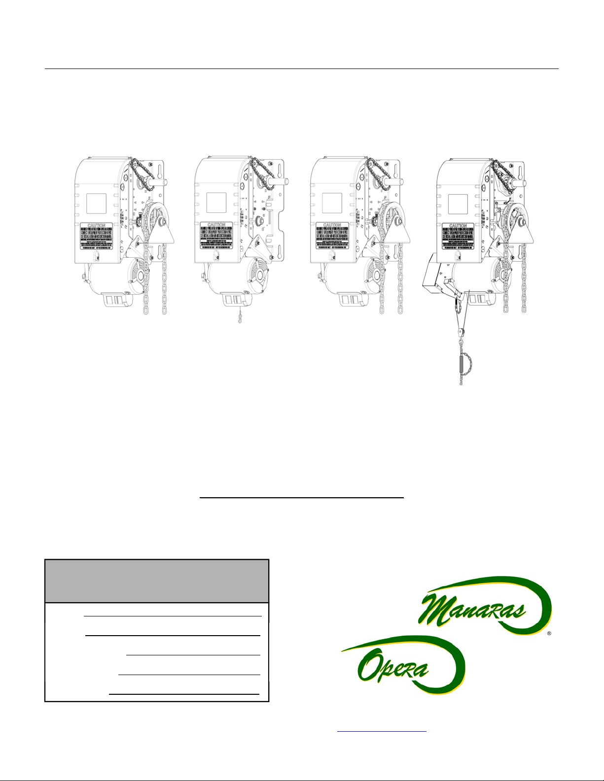
Commercial & Industrial Heavy Duty Jackshaft Operator
Commercial & Industrial Heavy Duty Jackshaft Operator
(For sectional doors, rolling doors and grilles)
(For sectional doors, rolling doors and grilles)
Opera-H
Opera-H
(OPH)
(OPH)
READ AND FOLLOW ALL INSTRUCTIONS.
SAVE THESE INSTRUCTIONS.
GIVE TO END-USER.
Serial #
Model #
Wiring Diagram #
Project #/Name
Opera-J
Opera-J
(OPJ)
(OPJ)
Electro-Mechanical Control
Electro-Mechanical Control
Opera-HJ
Opera-HJ
(OHJ)
(OHJ)
Opera-SH
Opera-SH
(OSH)
(OSH)
Door #/Name
For technical support, please call 1-800-361-2260 or visit www.manaras.com for more information
Page 2

2
TABLE OF CONTENTS
Installation Instructions............................................................................................................................................... 3
1 General Specifications and Dimensions (OPH / OPJ / OHJ)..............................................................................................................................4
2 General Specifications and Dimensions (OSH)...................................................................................................................................................5
3 Door & Operator Hardware..................................................................................................................................................................................6
3.1 Delivery of Operator..................................................................................................................................................................................6
3.2 Hardware Supplied....................................................................................................................................................................................6
4 Operator Installation.............................................................................................................................................................................................7
4.1 Operator Mounting Options.......................................................................................................................................................................7
4.2 Operator Mounting Holes..........................................................................................................................................................................7
4.3 Sprockets, Spreader Bar and Drive Chain Installation.............................................................................................................................8
5 Operator Control Box...........................................................................................................................................................................................9
6 Manual Hand Chain and Disconnect Chain.......................................................................................................................................................10
6.1 Installation...............................................................................................................................................................................................10
6.2 Operating Mode.......................................................................................................................................................................................11
7 Limit Switches & Limit Cams: Adjustment & Functionality.................................................................................................................................13
7.1 Limit Switch Functionality........................................................................................................................................................................13
7.2 Limit Switch Adjustments: Open and Close Cam Settings.....................................................................................................................13
7.3 Advanced Limit Switch Adjustments.......................................................................................................................................................13
7.4 Limit Switch Adjustment Using Manual Hand Chain (if applicable)........................................................................................................14
7.5 Limit Switch Adjustment Without Manual Hand Chain (if applicable).....................................................................................................14
8 Electrical Wiring.................................................................................................................................................................................................15
8.1 Low Voltage (Controls) and High Voltage (Power) Connections............................................................................................................16
8.2 Main Power Supply Connection..............................................................................................................................................................16
8.3 Wall-Button Connection...........................................................................................................................................................................17
8.4 Optional Accessory Connections............................................................................................................................................................18
9 Operator Start-up...............................................................................................................................................................................................22
10 Clutch Adjustment..............................................................................................................................................................................................23
11 Electromechanical Circuit Programming (Contactor Circuit).............................................................................................................................24
11.1 Run Mode Settings..................................................................................................................................................................................24
11.2 On Site Modifications..............................................................................................................................................................................25
User Instructions........................................................................................................................................................ 26
1 Quick Fix Instructions.........................................................................................................................................................................................27
Maintenance Instructions........................................................................................................................................... 28
1 Preventative Maintenance Schedule.................................................................................................................................................................28
1.1 Mechanical Inspection.............................................................................................................................................................................28
1.2 Electrical Inspection................................................................................................................................................................................29
1.3 Band Brake Maintenance........................................................................................................................................................................30
2 Troubleshooting Guide.......................................................................................................................................................................................32
3 Electrical Drawings.............................................................................................................................................................................................34
3.1 1 Phase Operator – Hardwired Wiring....................................................................................................................................................34
3.2 3 Phase Operator – Hardwired Wiring....................................................................................................................................................35
3.3 External Wiring – Hardwired...................................................................................................................................................................36
4 Mechanical Exploded Views and Replacement Components...........................................................................................................................37
4.1 Opera Heavy-Duty Jackshaft General View...........................................................................................................................................37
4.2 Opera-H...................................................................................................................................................................................................38
4.3 Opera-J...................................................................................................................................................................................................39
4.4 Opera-HJ.................................................................................................................................................................................................40
4.5 Opera-SH................................................................................................................................................................................................41
4.6 Opera Brake (BRAKE 013).....................................................................................................................................................................42
4.7 Opera Control Box - Hardwired...............................................................................................................................................................43
4.8 Replacement Motors, Transformers, Solenoids, Relays and Resets.....................................................................................................44
Notes............................................................................................................................................................................ 45
Warranty...................................................................................................................................................................... 47
For technical support, please call 1-800-361-2260 or visit www.manaras.com for more information
Page 3
3
Installation Instructions
IMPORTANT INSTALLATION INSTRUCTIONS
WARNING
TO REDUCE THE RISK OF SEVERE INJURY OR
DEATH TO PERSONS:
1. READ AND FOLLOW ALL INSTALLATION INSTRUCTIONS.
2. Install only on a properly operating and balanced door. A door that is operating
improperly could cause severe injury. Have qualified service personnel make repairs
to cables, spring assemblies and other hardware before installing the operator.
3. Remove all pull ropes and remove, or make inoperative, all locks (unless
mechanically and/or electrically interlocked to the power unit) that are connected to
the door before installing the operator.
4. Installation of this door operator must be done by a qualified installer.
5. Verify that the operator is correct for type, size of door and frequency of use per the
operator specifications.
6. Install the door operator at least 8 feet (2,44 m) or more above the floor if the operator
has exposed moving parts. Covers or guarding, provided by the manufacturer, must
be installed when the operator is mounted less than 8 feet (2,44 m) above the floor.
7. Do not connect the door operator to the source of power until instructed to do so.
8. Locate the control station: (a) within sight of the door, (b) at a minimum height of
5 feet (1,5 m) above floors, landings, steps or any other adjacent walking surface so
small children cannot reach it, and (c) away from all moving parts of the door.
9. Install the Entrapment Warning Placard next to the control station in a prominent
location.
10. For products having a manual release, instruct the end user on the operation of the
manual release.
11. If you have any questions about the safety of the door operating system, do not install
the operator, contact Manaras-Opera at 1-800-361-2260.
For technical support, please call 1-800-361-2260 or visit www.manaras.com for more information
Page 4
4
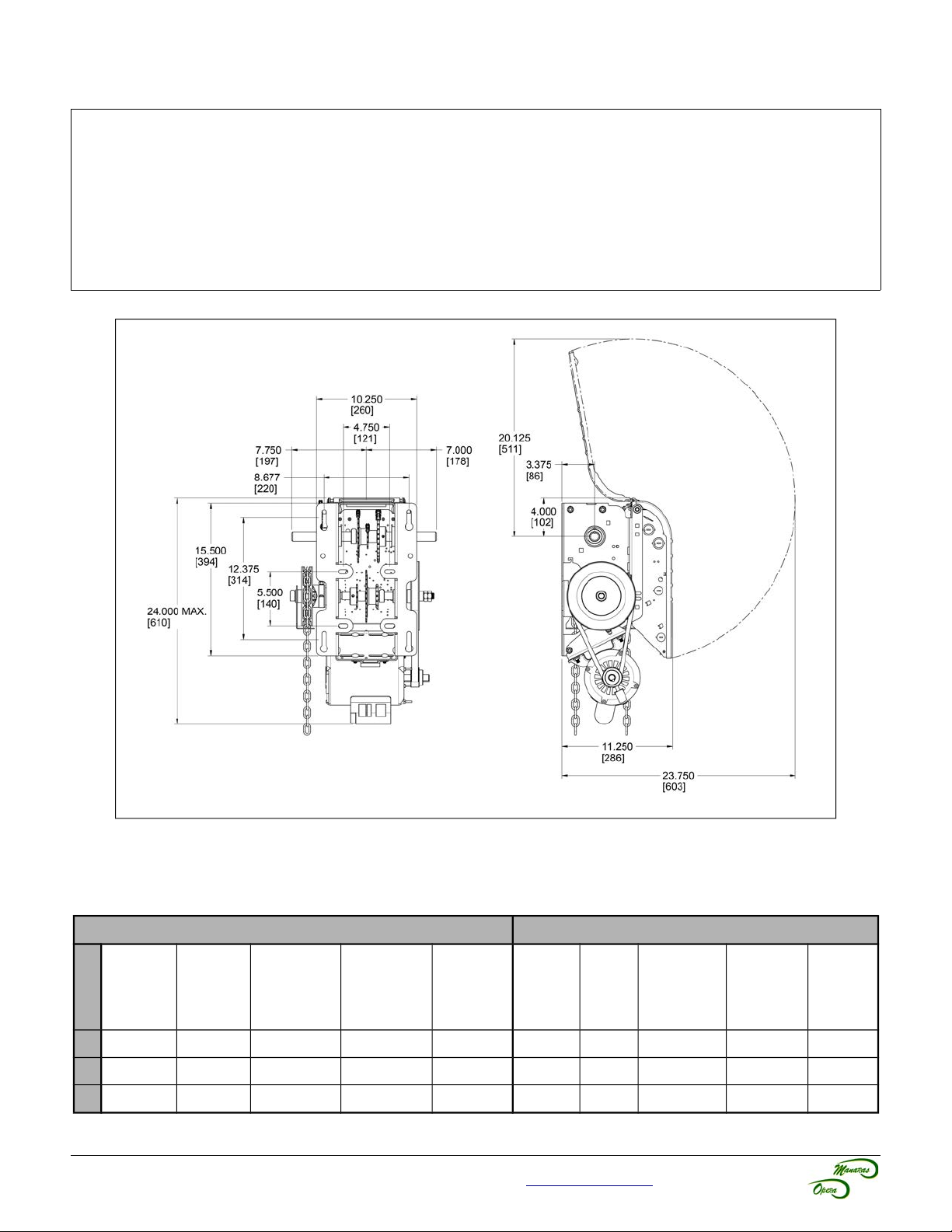
1 General Specifications and Dimensions (OPH / OPJ / OHJ)
SUPPLY VOLTAGE...............................115, 230 VAC single-phase, 208, 460, 575 VAC three-phase
CONTROL VOLTAGE............................24 VAC class 2 transformer, 2 amp fuse type ACG
MOTOR.................................................Continuous duty 1/2, 3/4, 1 horsepower
OPERATOR OUTPUT SPEED..............41 RPM
NET WEIGHT (Operator only)...............86 Lbs (39 Kg) for 1/2HP 115V Opera-H model
STANDARD WIRING TYPE..................C2 (momentary contact to open/stop and constant-pressure-to-close)
APPLICATION.......................................Heavy duty for sectional doors, rolling doors and grilles
DUTY.....................................................25 cycles/hour or 100 cycles/day maximum
Figure 1 - Opera-H, Opera-J and Opera-HJ Dimensions
Table 1 - Operator Selection Guide (OPH / OPJ / OHJ)
Maximum Area in Square Feet (general guideline)
Rolling Doors Sectional Doors
Insulated
HP
Steel
½ 157 236 260 319 358 196 245 314 343 392
¾ 206 294 358 451 515 270 319 441 490 549
1 255 358 446 574 613 294 392 490 564 613
16 ga
Steel
For technical support, please call 1-800-361-2260 or visit www.manaras.com for more information
Steel Grilles
20 ga
Steel
Alu. Door
22 ga Steel
Alu. Grilles
24 ga
Steel
Steel
18 ga
ins.
Steel
18 ga
20 ga
ins.
Wood
Steel 20 ga,
22 & 24 ga
ins.
Alu. Steel
22 & 24 ga
Fiber
Glass
Page 5
5
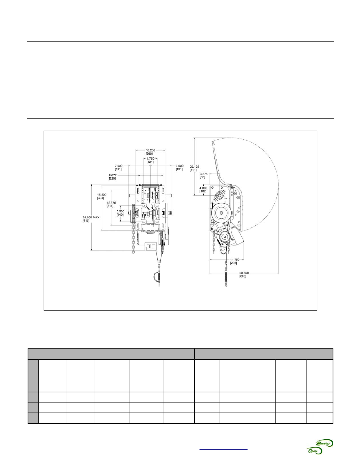
2 General Specifications and Dimensions (OSH)
SUPPLY VOLTAGE...............................115, 230 VAC single-phase, 208, 460, 575 VAC three-phase
CONTROL VOLTAGE............................24 VAC class 2 transformer, 2 amp fuse type ACG
MOTOR.................................................Continuous duty 1/2, 3/4, 1 horsepower
OPERATOR OUTPUT SPEED..............41 RPM
NET WEIGHT (Operator only)...............96 Lbs (44 Kg)
STANDARD WIRING TYPE..................C2 (momentary contact to open/stop and constant-pressure-to-close)
APPLICATION.......................................Ultra high-end heavy duty v-belt drive for sectional doors, rolling doors and
grilles
DUTY.....................................................25 cycles/hour or >100 cycles/day
Figure 2 - Opera-SH Dimensions
Table 2 - Operator Selection Guide (OSH)
Maximum Area in Square Feet (general guideline)
Rolling Doors Sectional Doors
Insulated
HP
Steel
½ 157 236 260 319 358 196 245 314 343 392
¾ 206 294 358 451 515 270 319 441 490 549
1 255 358 446 574 613 294 392 490 564 613
16 ga
Steel
For technical support, please call 1-800-361-2260 or visit www.manaras.com for more information
Steel Grilles
20 ga
Steel
Alu. Door
22 ga Steel
Alu. Grilles
24 ga
Steel
Steel
18 ga
ins.
Steel
18 ga
20 ga
ins.
Wood
Steel 20 ga,
22 & 24 ga
ins.
Alu. Steel
22 & 24 ga
Fiber
Glass
Page 6
6
3 Door & Operator Hardware
3.1 Delivery of Operator
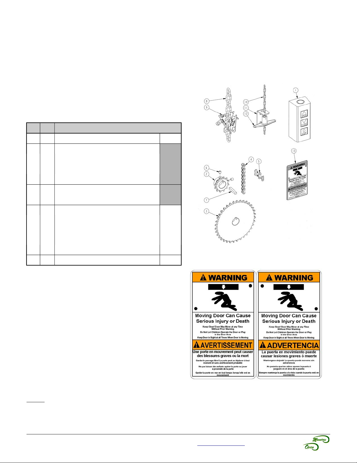
Upon delivery of your OPERA jackshaft operator, inspect the unit immediately for any shipping damages. Verify that
you have received all the hardware parts pertaining to your operator model, as listed in Table 3 and shown in
Figure 3. If ordered, other items such as radio controls or other types of optional equipment may be present. If any
item is missing or if there is evidence of damage, call the transport company or your direct supplier.
3.2 Hardware Supplied
Table 3 - Standard Hardware Parts Supplied
No Qty Description
1 1 3-Push-button station (open/close/stop)
2 1 Operator sprocket
3 1 Door sprocket
4 1 #41/#50 Drive chain, 4ft
5 1 #41/#50 Chain link
(1)
(1)
(1) (2)
(1)
Lxxxx
Hxxxx
Gxxxx
6 4 5/16-18 x 5/16” Set screw
7 2 Key 1/4” x 1-1/2”
8 1 Pocket wheel hand chain, 24ft
9 1 Chain keeper for hand chain
10 1 Disconnect chain, 14ft
(3) (4)
(4)
(3) (5)
11 1 Chain keeper for disconnect chain
12 1 Handle for disconnect chain
(5)
13 1 Entrapment Warning Placard
(1) Differs according to operator model and door characteristics
(2) 5ft for 42/54/60 tooth door sprocket, 8ft for 72 tooth door sprocket
(3) Quantity = 2 times door shaft height minus 4ft
(4) Only supplied with OMH/OPH/OHJ/OBH/OSH/OGH/MGH/GH
(5) Only supplied with OMJ/OPJ/OSH/MGH/GH
HD1HBAG
(5)
Figure 3 - Standard Jackshaft Hardware
Figure 4 - Entrapment Warning Placard
NOTE: Install the Entrapment Warning Placard (shown in Figure 4), next to the control station, visible in the area of
the door.
For technical support, please call 1-800-361-2260 or visit www.manaras.com for more information
Page 7
7
4 Operator Installation
4.1 Operator Mounting Options
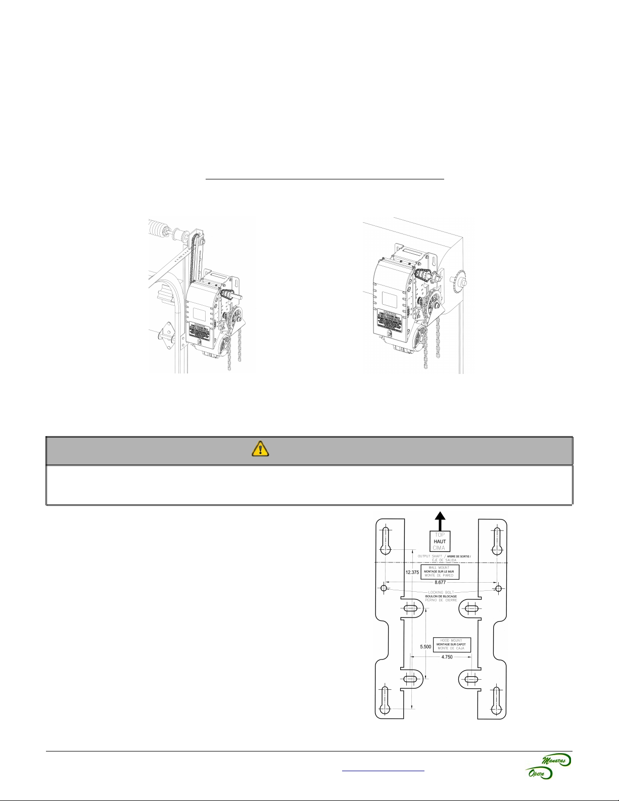
The jackshaft operator line has a dual output shaft. These operators may be wall-mounted on either the left hand side
or the right hand side of a sectional door. They can also be hood-mounted, using BRACKET111 (sold separately), or
shelf-mounted on either side of the door.
The standard jackshaft hoist model comes with a chain hoist located on the right of the operator. If the application
requires that the chain hoist be located on the left of the operator (ex: rolling doors, left operator hood mounting), it
must be requested at time of order. Do not attempt to modify the chain hoist yourself.
This operator is not intended to be installed on horizontal slide doors.
Figure 5 - Right Side Wall Mount
(Chain Hoist on Right)
Figure 6 - Right Side Hood Mount with
BRACKET111 (Chain Hoist on Right)
4.2 Operator Mounting Holes
CAUTION
The operator has exposed moving parts and to prevent access to the pinch points, the operator must be installed
at least 8 feet (2,44 m) or more above the floor. Alternatively, covers or guarding, provided by the manufacturer,
must be installed when the operator is mounted less than 8 feet (2,44 m) above the floor.
1. Ensure that the wall or mounting surface provides
adequate support for the operator. The surface must be
rigid enough to prevent any play between the operator
and door shaft. Manaras-Opera recommends the use of
BRACKET111 for hood-mount application.
2. Locate the four mounting holes, as shown in Figure 7.
3. The optimum distance between the door shaft and the
operator drive shaft is between 12" and 15".
4. Secure BRACKET111 to the end bracket of the rolling
door or mount the operator to the wall with 3/8" thrubolts. If the wall construction prohibits the use of thrubolts, then appropriate and sufficiently sized lag bolts
and anchors may be used.
5. Only tighten the bolts after having adjusted tension of
the drive chain, as shown in section 4.3, p.8.
6. Ensure that the door and operator shafts are parallel.
Figure 7 - Opera Mounting Holes
For technical support, please call 1-800-361-2260 or visit www.manaras.com for more information
Page 8
8
4.3 Sprockets, Spreader Bar and Drive Chain Installation
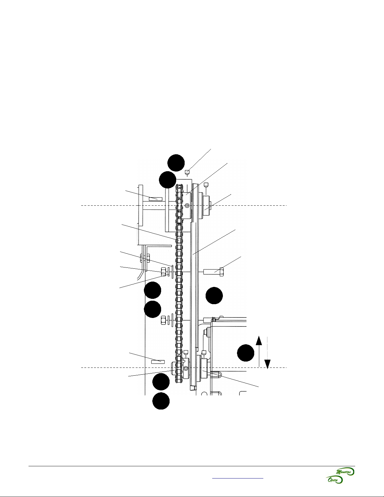
The hardware components shown in Figure 8 have been supplied with your operator.
1. Place the door sprocket loosely on the door shaft.
2. Place the operator drive sprocket on the appropriate side of the operator and align it with the drive sprocket of
the operator.
3. Lock the operator and door sprockets in place by inserting the keys and tightening their respective set
screws.
4. Wrap the operator drive chain around the door sprocket and the operator sprocket. Shorten the drive chain to
the appropriate length. Use the chain link to attach the operator drive chain together.
5. Slide the operator to tighten the drive chain and then firmly tighten the mounting bolts.
6. Check the tension on the chain (there should be no more than a 1/4" of slack when the chain is depressed
between the sprockets).
7. Manaras-Opera recommends the use of a chain spreader (sold separately).
Set Screw
Door Shaft
Drive Chain
Washer 3/8
Nut 3/8-16
Lock Washer 3/8
Key
3
Door Sprocket
1
Spreader Collar
Chain Spreader
Bolt 3/8-16
(To attach chain
spreader)
4
7
6
Key
Operator Shaft
Operator Sprocket
2
5
Spreader Collar
3
Figure 8 - Hardware Components
For technical support, please call 1-800-361-2260 or visit www.manaras.com for more information
Page 9
9
5 Operator Control Box
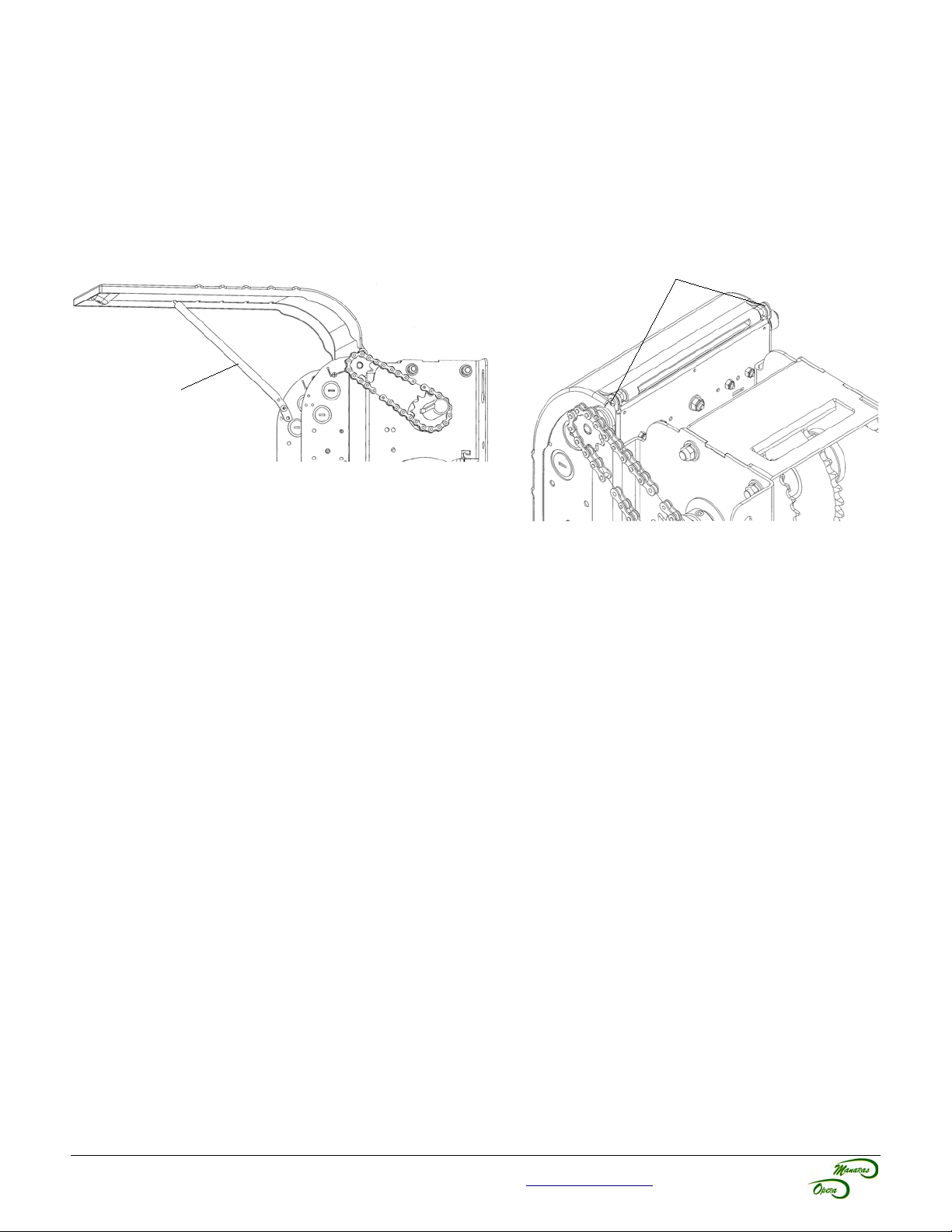
To open the control box cover, loosen the screw at the base of the cover. If the cover cannot be fully opened, the
retaining arm may be used to hold the cover in other positions, see Figure 9.
After installation, allow for proper clearance upon opening the control box cover. If the cover is obstructed from
opening, it is possible to remove the cover by unscrewing it from the box, see Figure 10.
Always close the cover before operating the door.
Screws
Retaining Arm
Figure 9 - Open Control Box Cover
Figure 10 - Unscrewing Screws from
Control Box Cover
For technical support, please call 1-800-361-2260 or visit www.manaras.com for more information
Page 10
10
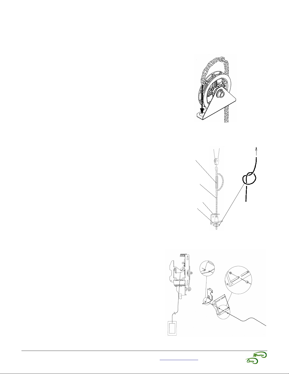
6 Manual Hand Chain and Disconnect Chain
6.1 Installation
6.1.1 Chain Hoist (Opera-H / SH / HJ)
Before pulling the hand chain through the pocket wheel, pull the limit
cam's retaining bracket back. Turn the cams to the center of the limit
shaft to be sure that they are not being mechanically driven through
their normal limit switch end positions.
1. Run the hand chain through the pocket wheel and through
the chain guide, see Figure 11.
2. Allow both ends of the chain to hang down toward the
ground until both ends are approximately 2 feet (0.6 m) from
the floor. Cut the hand chain if necessary.
3. Connect both ends of the hand chain together.
Figure 11 - Hand Chain Installation
6.1.2 Disconnect Chain (Opera-J / SH)
1. Link the disconnect chain to the hook located at the
extremity of the operator's disconnect mechanism, see
Figure 12.
2. Install the handle under the chain keeper to facilitate
handling of the chain.
3. Under the handle, make a knot in order to fasten the end of
the chain.
Disconnect
Mechanism from
Operator
Disconnect Chain
6.1.3 Emergency Egress (Opera-HJ)
This operator is built to receive a quick disconnect in case of an
emergency egress.
1. Pass the cable housing (from the emergency egress
control) through the holes provided on the frame of the
operator, see Figure 13.
2. Attach the end of the egress cable to the disconnect lever.
3. Secure positioning of the cable housing with two adjustment
collars.
Chain Keeper
Handle
Figure 12 - Disconnect Chain
Knot
Figure 13 - Emergency Egress
For technical support, please call 1-800-361-2260 or visit www.manaras.com for more information
Page 11
11
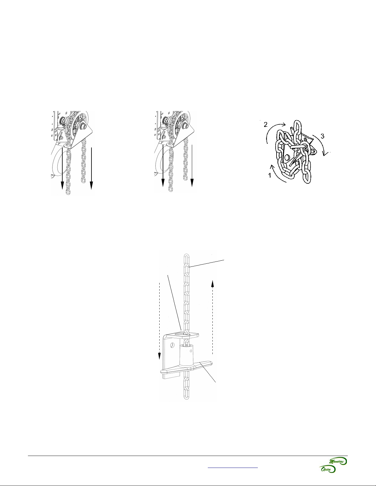
6.2 Operating Mode
6.2.1 Opera-H (Hoist-a-matic® Chain Hoist System)
The automatic emergency chain hoist disconnect mechanism is provided in order to operate the door manually. A floor
level disconnect is not required. In one simple step and by pulling the hand chain in the desired direction, the following
operations may be successfully completed, see Figure 14.
1. Manual Mode 2. Return to Electric Mode 3. Storage
Pull chain on either side
to operate door.
PULL
PULL
Wiggle chain until it
moves freely.
WIGGLE
WIGGLE
Figure 14 - Hoist-a-matic®
Follow the 3 steps shown below to
attach the chain (when not in use)
to the chain keeper.
STORE
STORE
6.2.2 Opera-J
This operator has a floor level disconnect to disconnect the door from the electrical motor and is ready to be manually
operated, see Figure 15.
Disconnect Chain
Chain Keeper
Pull the handle and
attach the
disconnect chain to
the chain keeper for
manual operation.
Release the tension from
the disconnect chain to
return to electrical mode.
Handle
Figure 15 - Floor
Level Disconnect
Chain
For technical support, please call 1-800-361-2260 or visit www.manaras.com for more information
Page 12
12
6.2.3 Opera-HJ
See section 6.2.1 for Chain Hoist Operation or see section 6.1.3 for Direct “on-the-door” Manual Operation.
Activation of the quick disconnect keeps the operator disconnected mechanically and electrically for manual
operation.
6.2.4 Opera-SH
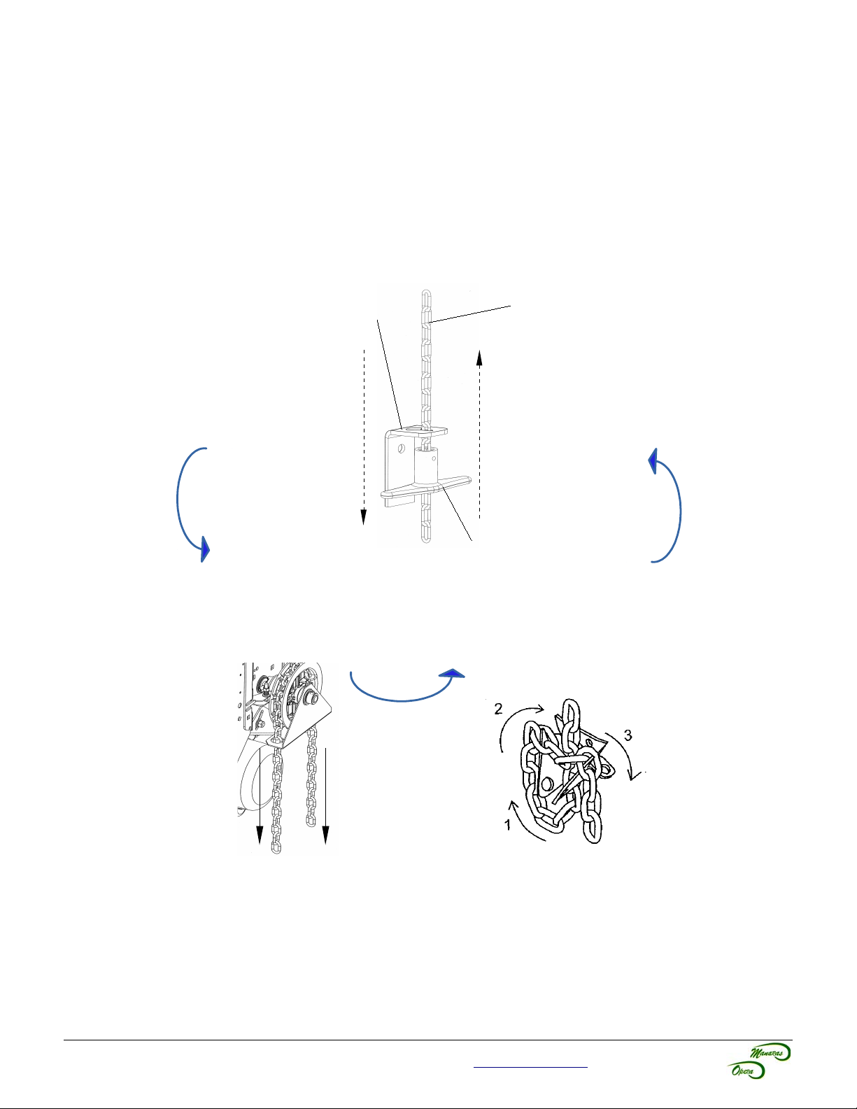
This operator has a floor level hoist engagement lever to:
– disconnect the electrical control of the operator
– release the brake
– engage the manual hoist mechanism, see Figure 16
Chain Keeper
1. Engagement 4. Return to Electrical Mode
Pull the handle and
attach the disconnect
chain to the chain
keeper for manual
operation.
Handle
2. Manual Mode 3. Storage
Pull chain on either side
to operate door.
Follow the 3 steps shown below to
attach the chain (when not in use)
to the chain keeper.
Disconnect Chain
Release the tension from
the disconnect chain to
return to electrical mode.
PULL
PULL
STORE
STORE
Figure 16 - Hoist Engagement and Hoist Operation
For technical support, please call 1-800-361-2260 or visit www.manaras.com for more information
Page 13
13
7 Limit Switches & Limit Cams: Adjustment & Functionality
WARNING
To reduce risk of SEVERE INJURY or DEATH to persons:
• Do not attempt to make limit switch adjustments unless power has been electrically disconnected.
7.1 Limit Switch Functionality
Open Limit Switch and Advanced Open Limit Switch
When activated, the Open Limit Switch will stop the operator while the door is travelling in the upward direction.
Should be adjusted accordingly to stop door in fully opened position. The Advanced Open Limit Switch is used for a
radio-control feature and to activate the Timer to Close feature (if used).
Close Limit Switch and Advanced Close Limit Switch
When activated, the Close Limit Switch will stop the operator while the door is travelling in the downward direction.
Should be adjusted accordingly to stop door in fully closed position. The Advanced Close Limit Switch is used for the
operation of a reversing edge or external entrapment protection devices. With this limit switch, the floor is not
considered as an obstacle, therefore the door does not reverse its movement once it reaches the floor.
7.2 Limit Switch Adjustments: Open and Close Cam Settings
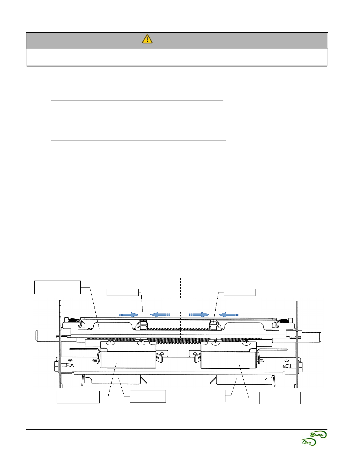
This operator is equipped with the ACCU-CAM® feature, for precise and quick one-handed limit setting adjustments.
To adjust the limit cams, see Figure 17.
1. Pull the cam's retaining bracket back.
2. Turn the cams for limit adjustment: turning cams toward the center of the limit shaft increases door travel or
turning the cams toward the limit switch decreases door travel.
7.3 Advanced Limit Switch Adjustments
The Advanced Close Limit Switch must be field adjusted in order to deactivate the reversing edge or external
entrapment protection device at a maximum of 6 in (15,2 cm) from the floor. The adjustment can be performed by
changing the position of the Advance Close Limit Switch on its slotted support bracket.
Cam Retaining
Bracket
Open Side
Open Cam Close Cam
Increase
Door Travel
Decrease
Door Travel
Close Side
Increase
Door Travel
Advanced Open
Limit Switch
Figure 17 - Limit Switches and Cams Adjustment
For technical support, please call 1-800-361-2260 or visit www.manaras.com for more information
Open Limit
Switch
Close Limit
Switch
Advanced Close
Limit Switch
Page 14
14
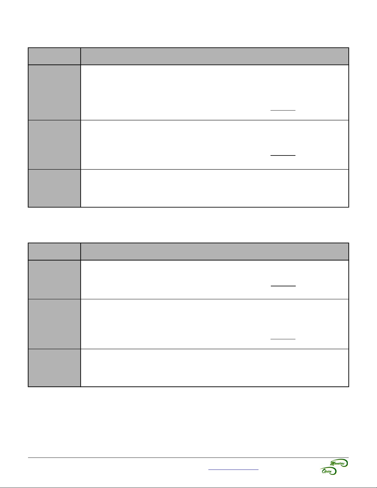
7.4 Limit Switch Adjustment Using Manual Hand Chain (if applicable)
Table 4 - Limit Switch Adjustment Procedures
Limit Switch Adjustment Procedures
1. Using the hoist, manually raise the door to a nearly opened position or desired open
position.
2. Pull the cam-retaining bracket from the Open side, see Figure 17, and rotate the Open
Open Limit
Advanced
Close Limit
cam manually until it activates the Open Limit Switch sufficiently so that a “click” can be
heard.
3. Release cam-retaining bracket and make sure that the bracket engages in the slots of
both cams.
1. Using the hoist, manually lower the door to approx. 6” above the ground.
2. Pull the cam-retaining bracket from the Close side, see Figure 17, and rotate Close cam
manually until it activates the Close limit switch sufficiently so that a “click” can be heard.
3. Release cam-retaining bracket and make sure that the bracket engages in the slots of
both cams.
Limit Switch
Fine
Adjustment
1. Limit switch fine adjustment SHOULD be done after the main power supply is connected
to the operator. Refer to section Operator Start-up, Table 6, p.22.
Note: One (1) notch on cam is equal (=) to about ½” of the door travel.
7.5 Limit Switch Adjustment Without Manual Hand Chain (if applicable)
Table 5 - Limit Switch Adjustment Procedures (no hoist)
Limit Switch Adjustment Procedures
1. Move the open cam close to the open limit switch and proceed as per described in section
Open Limit
Advanced
Close Limit
Operator Start-up, Table 6, p.22.
2. Release cam-retaining bracket and make sure that the bracket engages in the slots of
both cams.
1. Pull the disconnect chain for manual operation.
2. Manually open the door approx. 6” above the ground.
3. Pull the cam-retaining bracket from the Close side, see Figure 17, and rotate Close cam
manually until it activates the Close limit switch sufficiently so that a “click” can be heard.
4. Release cam-retaining bracket and make sure that the bracket engages in the slots of
both cams.
Limit Switch
Fine
Adjustment
For technical support, please call 1-800-361-2260 or visit www.manaras.com for more information
1. Limit switch fine adjustment SHOULD be done after the main power supply is connected
to the operator. Refer to section Operator Start-up, Table 6, p.22.
Note: One (1) notch on cam is equal (=) to about ½” of the door travel.
Page 15
15
8 Electrical Wiring
WARNING
To reduce risk of SEVERE INJURY or DEATH to persons:
• All electrical wiring should be done by a qualified professional and in accordance to local
electrical codes.
• Always shut OFF the main power before performing any electrical intervention.
• Use proper wire gauge for incoming power line and for accessory connections.
• Install operator main circuit breaker next to operator for easy access for power shut-off.
• Use separate knockouts on operator control box for accessories and main power cables.
• Always separate low and high voltage wires.
• Operator should be properly grounded to the building ground and to the main power
supply ground lug.
• Always use suitable and appropriate rating circuit breakers for operator protection.
• Compare available power supply voltage to voltage on operator name plate prior to
electrical connection. Failure to connect appropriate power supply voltage may cause
serious damage to the operator.
NOTICE
• THE OPERATOR MUST BE ADEQUATELY PROTECTED AGAINST OVERCURRENT AND SHORTCIRCUIT.
• PLEASE REFER TO LOCAL ELECTRICAL CODE.
• PLEASE REFER TO NATIONAL ELECTRIC CODE (NFPA 70) ARTICLE 430 SECTION IV (430,51 /
430,52 / 430,53).
• PLEASE REFER TO CANADIAN ELECTRIC CODE (CSA 22,1) SECTIONS 28-200 / 28-206.
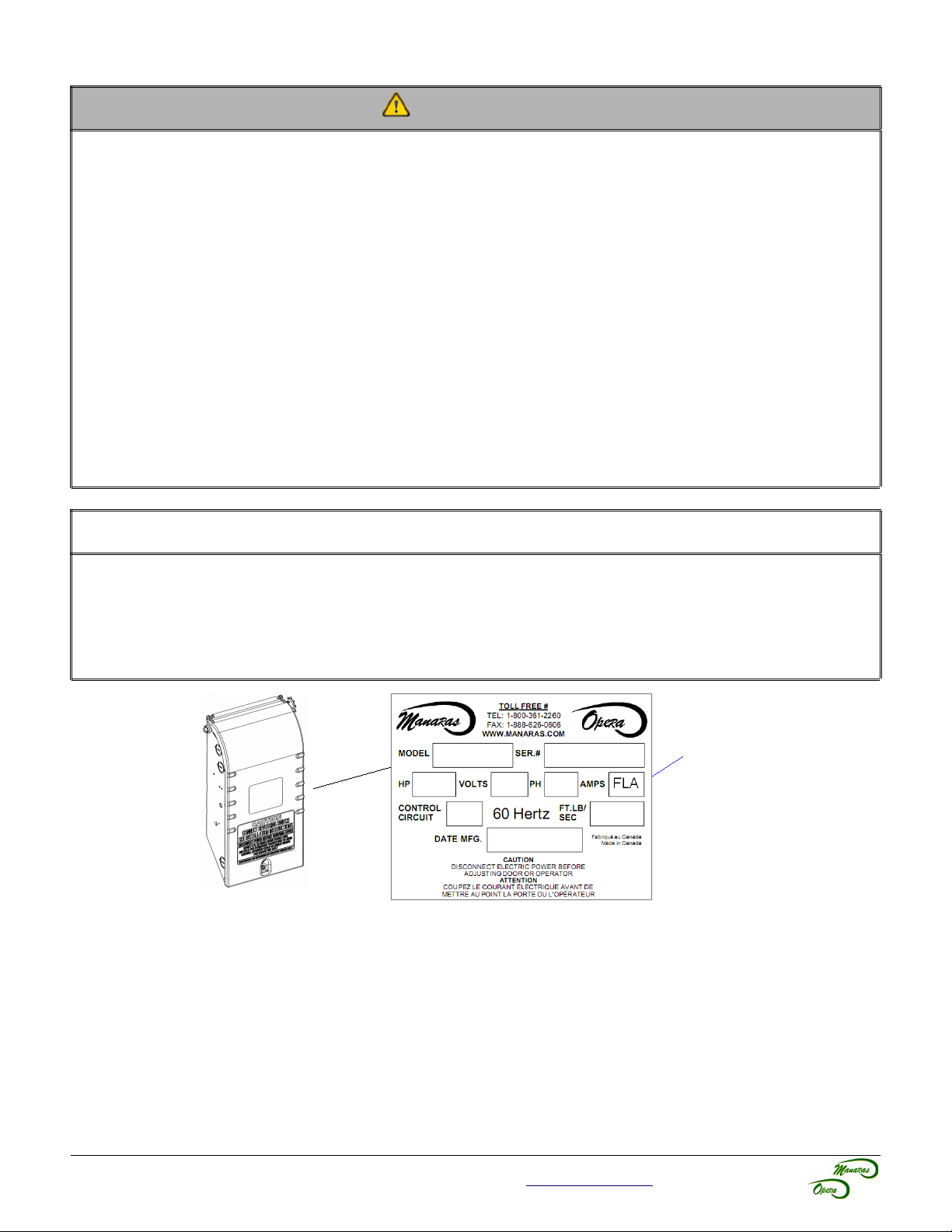
FLA = Full Load Amp
Guideline to determine the branch-circuit rating of the protective device [A]:
Time Delay Fuse: 1,75 x FLA
Non-Time Delay Fuse: 3,0 x FLA
A fuse that does not exceed the next higher standard ampere rating shall be permitted.
Example: If FLA = 3,8A
• Time Delay Fuse: 1,75 x 3,8A = 6,65A → Standard fuse to use: 10A
• Non-Time Delay Fuse: 3,0 x 3,8A = 11,4A → Standard fuse to use: 15A
For technical support, please call 1-800-361-2260 or visit www.manaras.com for more information
Page 16
16
NOTICE
• The installer MUST test for proper connection and functionality of the operator and its accessories
before leaving the job site.
• The installer should also perform a demonstration for the end-user.
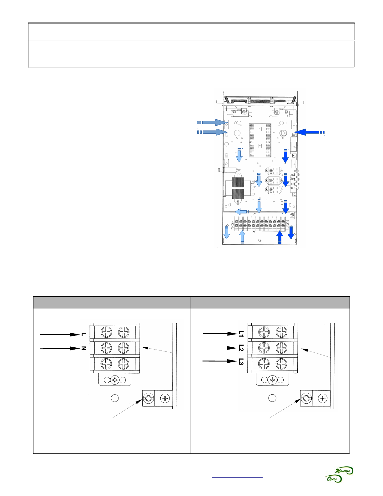
8.1 Low Voltage (Controls) and High Voltage (Power) Connections
1. Route the power line wire from the
right of the control box, as shown in
Figure 18.
2. Route all low voltage control wires
from the left of the control box, as
shown in Figure 18. KEEP LOW
VOLTAGE WIRES SEPARATE FROM
LINE VOLTAGE WIRES.
3. USE COPPER CONDUCTORS ONLY.
PowerControl
8.2 Main Power Supply Connection
Single-Phase (115/230V) Three-Phase (208/230-460-575V)
LIVE
NEUTRAL
Ground Lug
Correct motor rotation: Switch the BLUE and ORANGE
motor wires on the contactor.
Figure 18 - Low Voltage (Controls)
and High Voltage (Power)
Connections
Line 1
Line 2
Line 3
Power Terminal Block
Ground Lug
Correct motor rotation: Switch ANY TWO incoming lines
(phase) on the power terminal block.
Power Terminal Block
For technical support, please call 1-800-361-2260 or visit www.manaras.com for more information
Page 17
17
3
OPEN
CLOSE
STOP
4
5
2
OPEN
CLOSE
STOP
COM
OPEN
(OUVERTURE)
CLOSE
(FERMETURE)
STOP
(ARRÊT)
Link (Lier)
Open/Clo se/Stop
OPEN
CLOSE
COM
STOP
OPEN
(OUVERTURE)
CLOSE
(FERMETURE)
4
5
2
3
NO 3
4
NO 3
4
NC 1
2
STOP
(ARRÊT)
Link (Lier)
Ope n/C lose/Stop
OPEN
CLOSE
COM
STOP
OPEN
(OUVERTURE)
CLOSE
(FERMETURE)
KEY
(CLÉ)
4
5
3
2
NO 3
4
NO 3
4
NC 1
2
NO 3
4
Link (Lier)
Open/Close/Stop
OPEN
CLOSE
COM
STOP
OPEN
(OUVERTURE)
CLOSE
(FERMETURE)
KEY
(CLÉ)
4
5
3
2
NO 3
4
NO 3
4
NC 1
2
NO 3
4
LED
1
9
24 VAC
24 VAC
OPEN
COM
OPEN
(OUVERTURE)
4
3
NO 3
4
Link (Lier)
Ope n/C lose
OPEN
CLOSE
COM
OPEN
(OUVERTURE)
CLOSE
(FERMETURE)
4
5
3
NO 3
4
NO 3
4
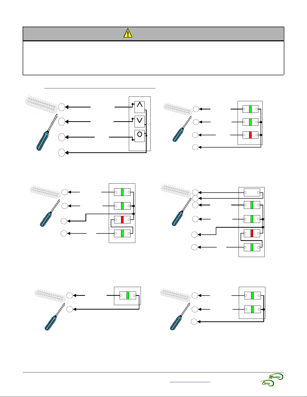
8.3 Wall-Button Connection
WARNING
• Wall controls must be mounted in clear view of the door, far enough from the door, or positioned such
that the user is prevented from coming in contact with the door while operating the controls and at least
5 feet (1,5 m) above the standing surface.
• Keep low voltage wires separate from line voltage wires.
• Use copper conductors only.
Push-Button Station (PBS) Connection
Figure 19 - STATION 020 / 084
3-PBS Open / Close / Stop
Figure 21 - STATION 079
3-PBS Open / Close / Stop with Key Lock-out
Figure 20 - STATION 041 / 049 / 056 / 076 / 078
3-PBS Open / Close / Stop
Figure 22 - STATION 080
3-PBS Open / Close / Stop with Key Lock-out and Light
Figure 23 - STATION 001 / 081
For technical support, please call 1-800-361-2260 or visit www.manaras.com for more information
1-PBS Open
Figure 24 - STATION 010 / 082
2-PBS Open / Close
Page 18
18
1
9
6
3
Always set the jumper located
inside the Interface Module on
N.O. (Normally Open)
ALIGNMENT
BLACK & WHITE
TRANSMITTER
RECEIVER
BLACK
TK-8200
Interface Module
POWER BEAM
RELAY
OUT
1 2 3 4 5 6
NO
NC
JMP
24VAC
24VAC
COM
SAFETY
BLACK & WHITE
BLACK
3
1
9
6
24VAC
COM
SAFETY
RX
42 3 51
Pwr
Com
NO
NC
Pwr
1 2
Pwr
Pwr
TX
24VAC
C1 [1]
3
1
9
SAFETY
COM
24VAC
24VAC
6
NO1 [2]
NC1 [3]
NC2 [4]
NO2 [5]
C2 [6]
P
P
BLUE
BROWN
ORANGE (COM)
BLACK (NO)
(NOT USED)
WHITE (NC)
3
1
9
SAFETY
COM
24VAC
24VAC
6
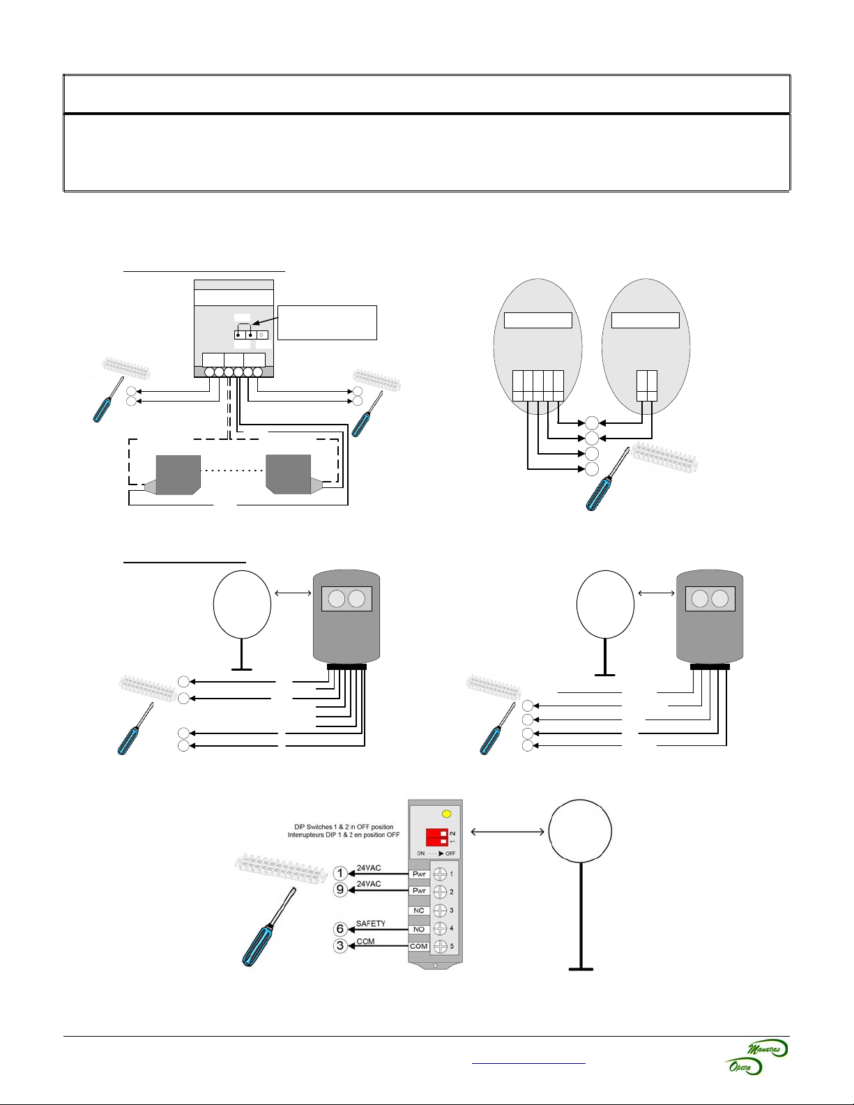
8.4 Optional Accessory Connections
NOTICE
• Photo cells must be installed facing each other across the door's path within 6” (15 cm) of the plane of
the door and the beam no more than 5-3/4” (14,6 cm) above the floor.
• Keep low voltage wires separate from line voltage wires.
• Use copper conductors only.
8.4.1 Electric Photo Cells / Photo Eyes (Non-Monitored)
Through Beam Type
Figure 25 - PHOTO 008
Reflective Type
Figure 27 - PHOTO 018
For technical support, please call 1-800-361-2260 or visit www.manaras.com for more information
Figure 26 - PHOTO 015 / 016 / 045 / 050 / 051 / 059
Figure 28 - PHOTO 038
Figure 29 - PHOTO 060
Page 19
19
Figure 32 - AIRSWITCH 009
RED
YELLOW (NO)
Adjustment screw
(Vis d'ajustement)
3
6
COM
SAFETY
WHITE
GREEN (NO)
3
6
COM
SAFETY
3
6
COM
SAFETY
2-Wire Edge
1
2
3
45
3
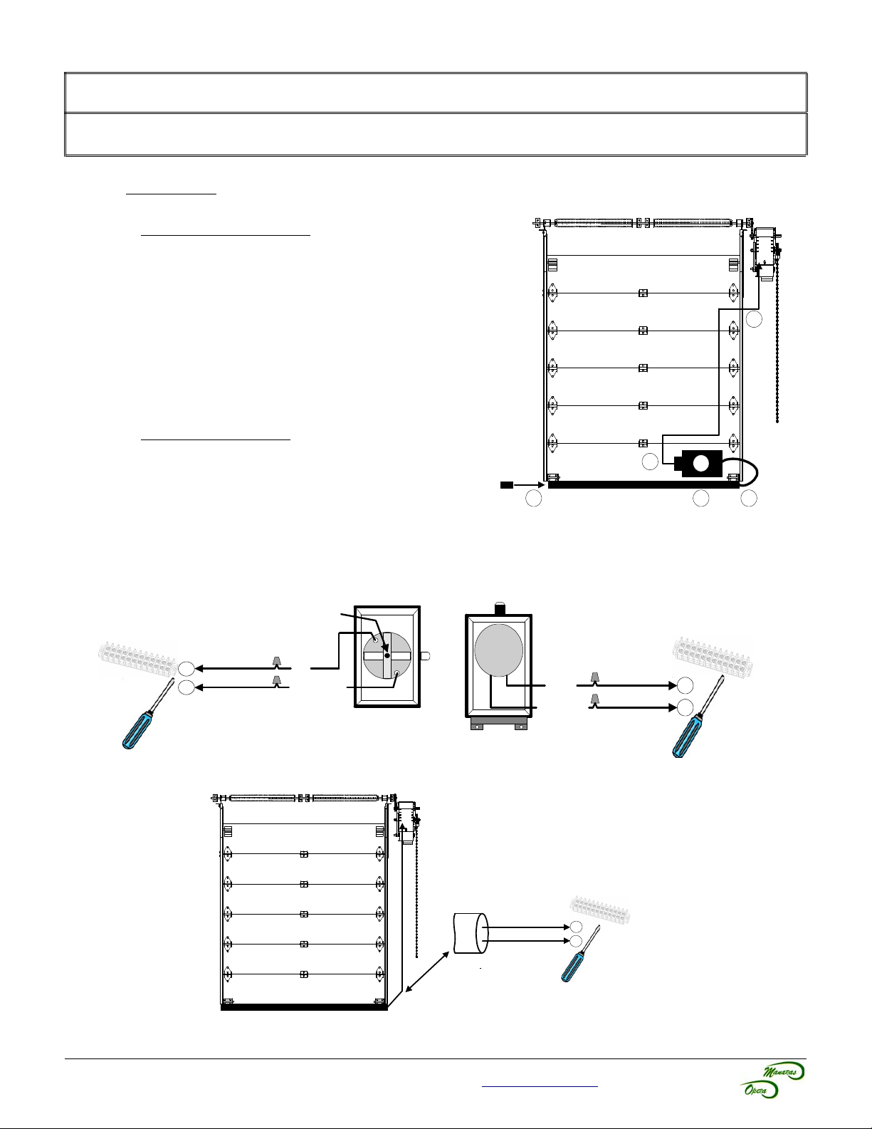
8.4.2 Reversing Edge Device (Non-Monitored)
NOTICE
• If the door is controlled by any device other than a constant pressure push-button station on close,
including a timer-to-close, a reversing edge must be connected.
Installation
Pneumatic Sensing Edge
1. Place the air switch in position, refer to Figure
30.
2. Place the air hose in position.
3. Use a coil cord or take-up reel to connect the air
switch to the operator terminals. Install electric
wires according to Figure 31 or Figure 32.
4. Connect one end of the air hose to the air
switch.
5. Place the air plug in the other end of the air
hose.
Electric Sensing Edge
1. Place the junction box in position, refer to Figure 30.
2. Place the sensing edge in position.
3. Use a coil cord or take-up reel to connect the
sensing edge wires to the operator terminals.
Install electric wires according to Figure 33.
4. Connect the sensing edge to the junction box.
5. N/A
Figure 30 - Reversing Edge
Figure 31 - AIRSWITCH 001 / 007
Figure 33 - Electric Reversing Edge
For technical support, please call 1-800-361-2260 or visit www.manaras.com for more information
Page 20
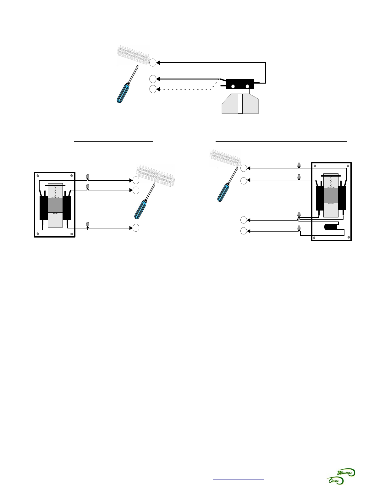
8.4.3 Pull Cord & Key Switch
3
8
4
O/C
For OPEN only
N.O.
COM
COM
OR (OU)
(Seulement pour OUVERTURE)
NO
COM
NO
COM
CLOSE
OPEN
COM
5
4
3
Place a jumper between
#8 & #9 on the board
(Installer un cavalier entre
#8 & #9 sur la plaquette)
NO
COM
NO
COM
2
COM
STOP
3
4
5
CLOSE
OPEN
STOP BUTTON
Figure 34 - PULLCORD 001 / 003 / 004 / 007
2-Position Key Switch 2-Position Key Switch & Stop Button
Recommendation: Put Control Board on C2
or E2 Mode (constant-pressure-to-close)
20
Figure 35 - KEYSWITCH 010 / 015
For technical support, please call 1-800-361-2260 or visit www.manaras.com for more information
Figure 36 - KEYSWITCH 019
Page 21
21
Manaras
3
24VOLTS
RELAY
RADIO POWER
X
X
X
Mount the Radio receiver directly
on the terminal strip provided on
the side of the control box
2 1
CONTACT
GND
24VAC
POWER
POWER
COM CONTACT
NO CONTACT
(NOT USED)
1
9
7
8
24VAC
24VAC
COM
OPEN/CLOSE
NC CONTACT
BLACK
WHITE
YELLOW
BLUE
(NO)
BROWN
GRAY
LOOP
(BOUCLE)
1
9
3
6
4
8
24VAC
24VAC
COM
OPEN/CLOSE
SAFETY
OPEN
OR (OU)
OR (OU)
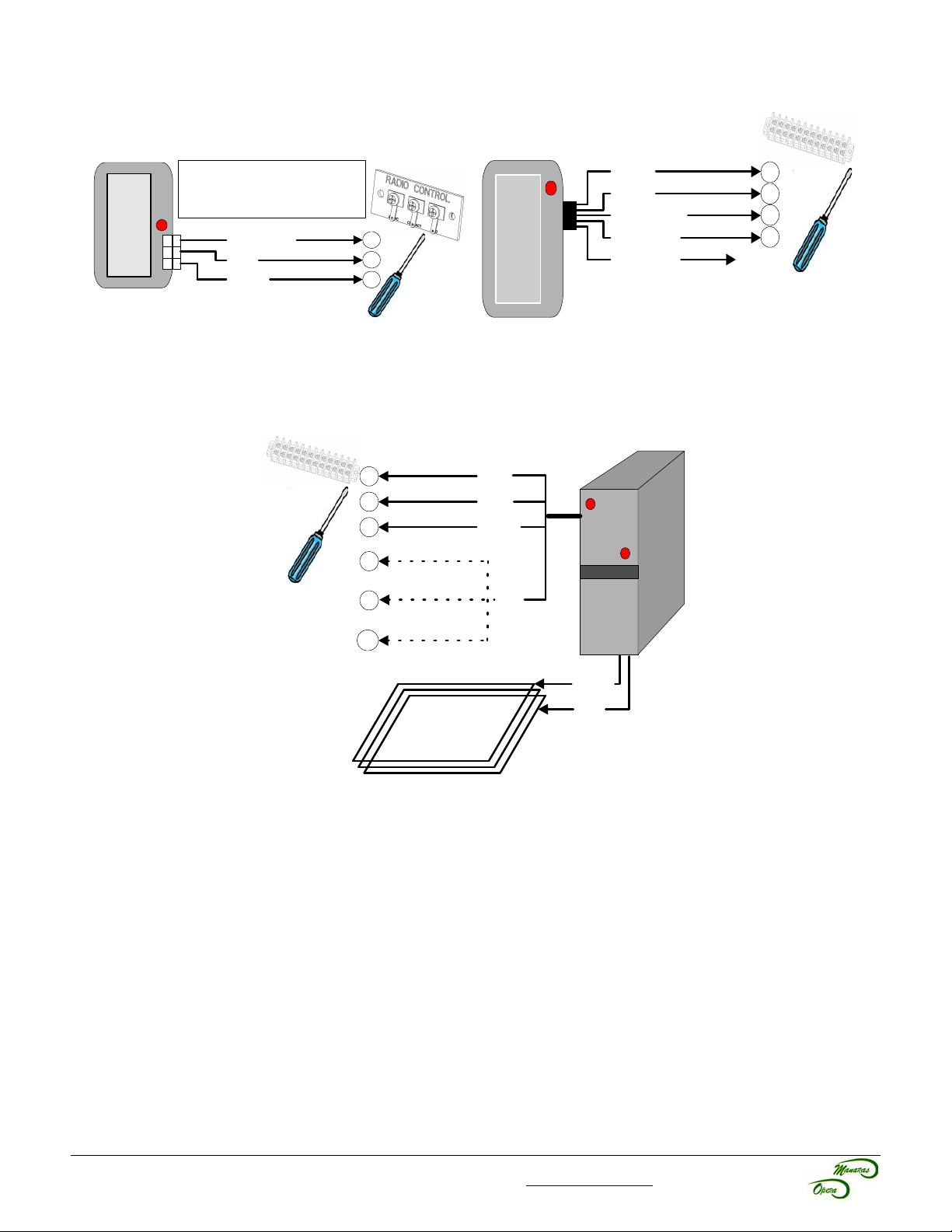
8.4.4 External Single-Button Radio Control Receiver
Figure 37 - RADIO 014 or RADIO 015
8.4.5 Vehicle Loop Detector
Figure 38 - Other Radio Receivers with 4 or 5-wires
Twist the two (2) leads (wires) a
minimum of 6 twists/foot
Figure 39 - Vehicle Loop Detector
8.4.6 Other Accessories
Additional accessories are available, such as:
• External Mid-Stop Switch
• External Timer Defeat Switch
Please contact your dealer or our inside sales department at 1-800-361-2260 for further information.
For technical support, please call 1-800-361-2260 or visit www.manaras.com for more information
Page 22
22
9 Operator Start-up
WARNING
To reduce risk of SEVERE INJURY or DEATH to persons:
• Personnel should keep away from a door in motion and keep the moving door in sight until it is
completely closed or opened. NO ONE SHOULD CROSS THE PATH OF A MOVING DOOR.
• Never go under a stopped, partially opened door.
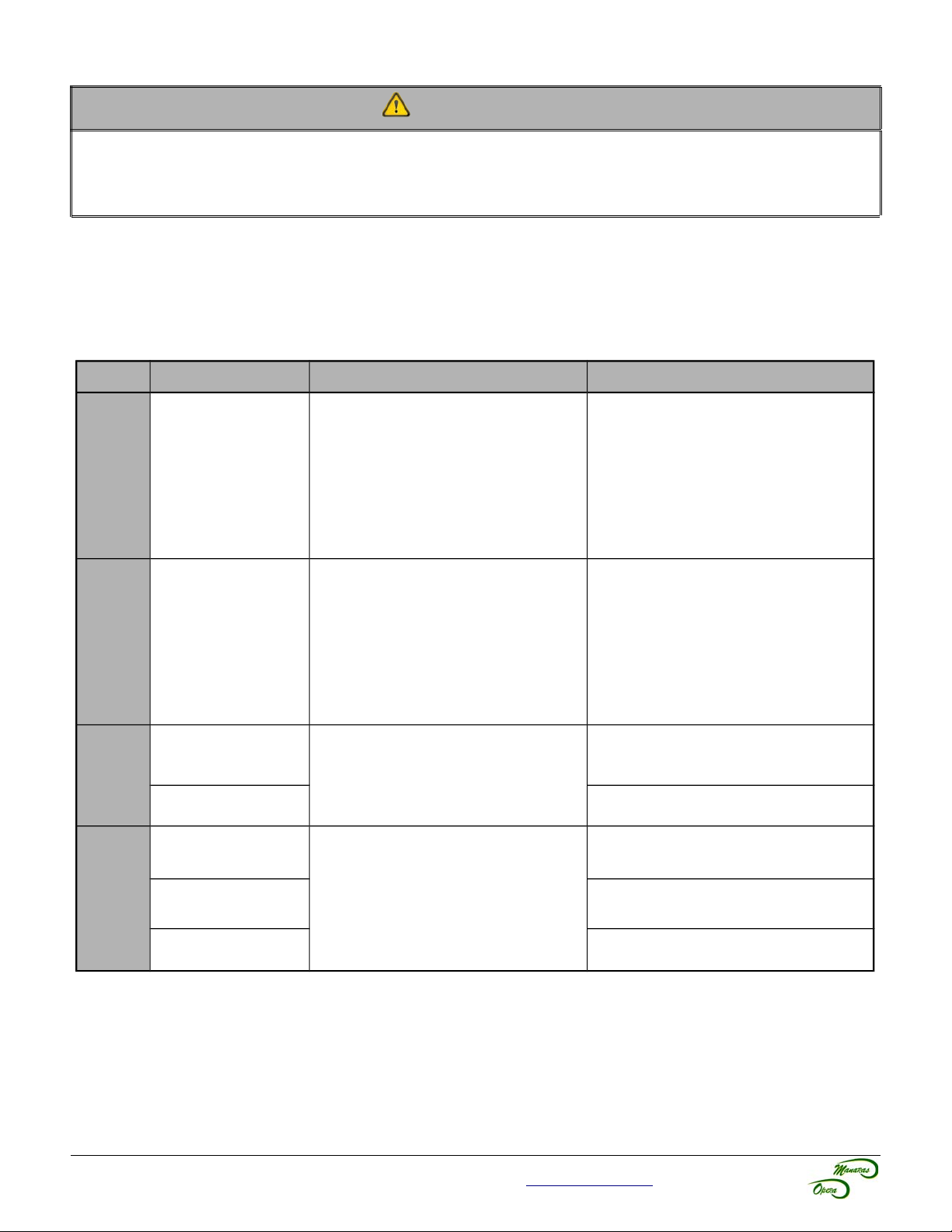
1. Turn power ON.
2. Use the wall-button station (Open/Close/Stop), external entrapment device or jumper wires for testing, see
Table 6.
Table 6 - Start-up and Testing Guide
Test Door Position Action Door Response
1. Press “OPEN”
OR
Momentarily touch #3 & #4 on the
Open
Close
Door at 6” from the
closed position
Door at fully open
position
main terminal with a jumper wire.
2. Check if door is stopped by Open
limit switch.
3. If required, re-adjust Open limit, as
shown in Figure 17, p.13.
1. Press “CLOSE”
OR
Momentarily touch #3 & #5 on the
main terminal with a jumper wire.
2. Check if door is stopped by Close
limit switch.
3. If required, re-adjust Close limit,
as shown in Figure 17, p.13.
Door should open instantly.
- C2 mode: Door should close as long
as the close button is activated.
- B2 mode: Door should close
instantly.
Sense
Edge
Open &
Close
(single-
button
radio)
A) Door at fully
closed position
B) Door is closing
(movement)
A) Door at fully
opened position
B) Door at fully
closed position
C) Door is closing
(movement)
For technical support, please call 1-800-361-2260 or visit www.manaras.com for more information
Activate external entrapment device
OR
Momentarily touch #3 & #6 on the
main terminal with a jumper wire.
Activate the single-button transmitter
OR
Momentarily touch #7 & #8 on the
main terminal with a jumper wire.
Door should stay at closed position.
Door should stop and then reverse to
fully opened position.
Door should close.
Door should open.
Door should reverse to fully opened
position.
Page 23
23
10 Clutch Adjustment
NOTICE
• The friction clutch is NOT intended to protect people. It is designed to protect the operator and door
system against potential damage.
• The friction clutch is factory adjusted during final testing. Proper adjustments should be done on site
according to the door characteristics and application.
• In order to avoid the door from getting damaged when the lock is on, the friction clutch must be properly
adjusted according to the instructions below.
Best Practices Encouraged by Manaras-Opera
Manaras-Opera recommends the installation of a hard stop at the end of the tracks
(ex. bolt, deformation of tracks, bumper spring, pusher spring, etc). With such installation,
the door is prevented from running out of the tracks. The clutch (torque limiter) will
prevent any damage to occur to the door system.
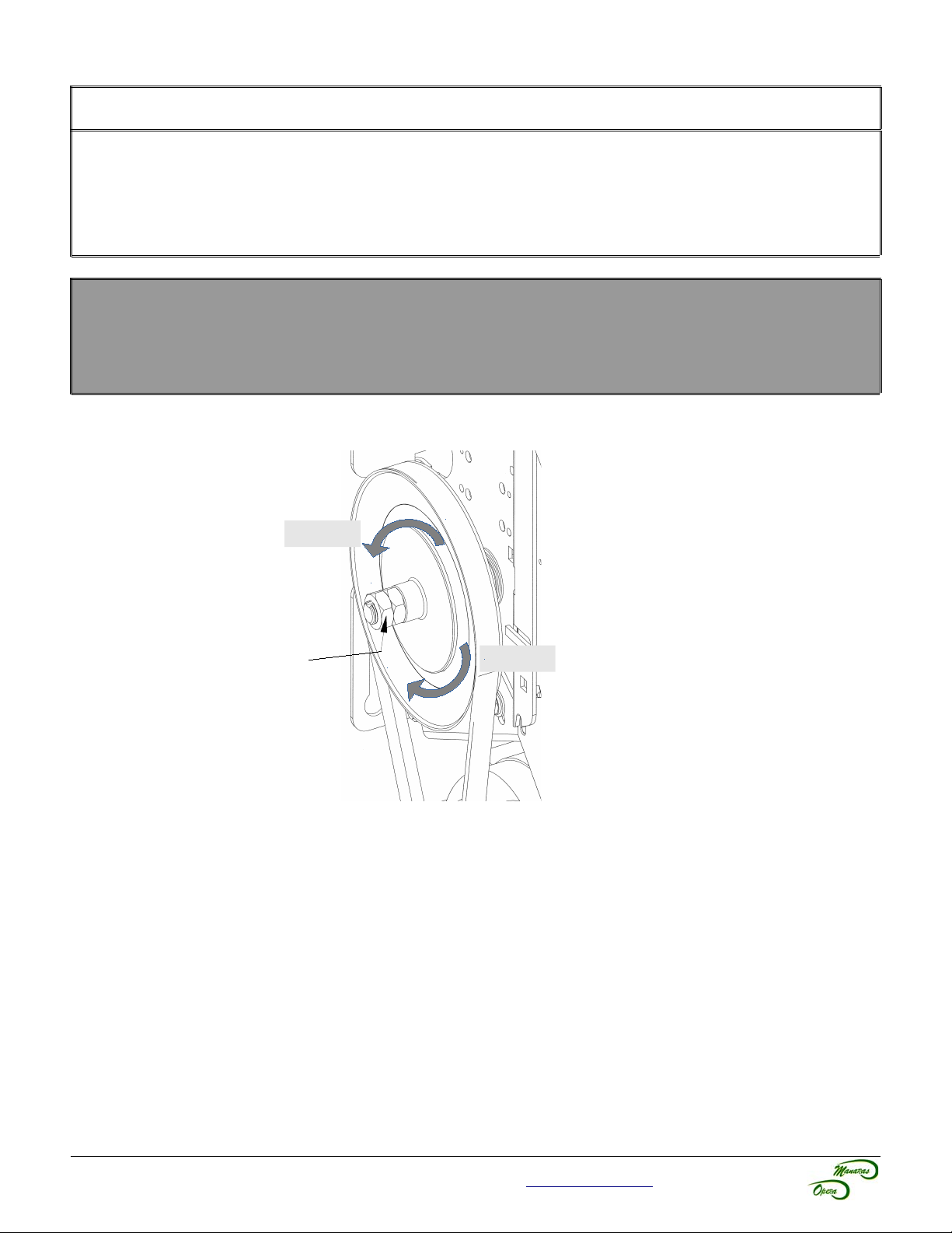
- Torque
Jam Nuts
Figure 40 - Clutch
Adjustment
To adjust the clutch:
1. Unlock the jam nuts with two (2) 15/16” keys, refer to Figure 40.
2. Rotate the nut counter-clockwise to release the tension.
3. Gradually rotate the nut clockwise until there is just enough tension to permit smooth operation (while still
allowing the clutch to slip if the door is obstructed).
4. Lock the jam nuts.
+ Torque
For technical support, please call 1-800-361-2260 or visit www.manaras.com for more information
Page 24
24
11 Electromechanical Circuit Programming (Contactor Circuit)
WARNING
To reduce risk of SEVERE INJURY or DEATH to persons:
• Manaras-Opera strongly recommends the use of external entrapment protection devices, especially in
the case of momentary contact to close (B2 wiring or Timer to Close).
11.1 Run Mode Settings
NOTICE
• Always return the door to fully closed position before performing any program settings.
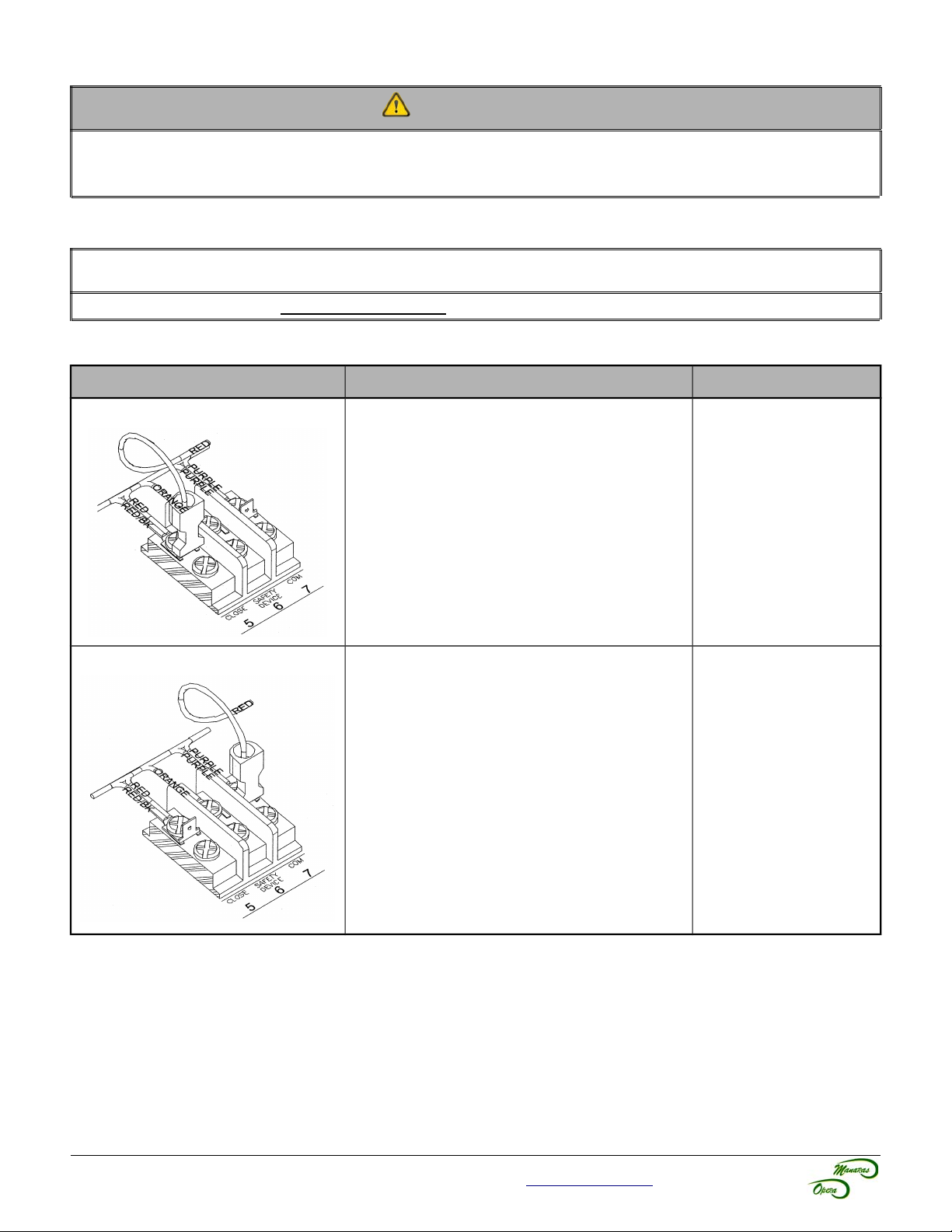
Mode Functions Operations
C2 • Momentary contact to open and stop,
constant-pressure-to-close with 3-button
station.
• Activation of safety devices will reverse the
door while closing.
• Auxiliary devices function as an Open control
and will reverse the door while closing.
B2 • Momentary contact to open, close and stop
with 3-button station.
• Activation of safety devices will reverse the
door while closing.
• Auxiliary devices function as an Open/Close
control and will reverse the door while
closing.
B2 Mode → C2 Mode
Move RED wire from
terminal #7 → #5.
C2 Mode → B2 Mode
Move RED wire from
terminal #5 → #7.
For technical support, please call 1-800-361-2260 or visit www.manaras.com for more information
Page 25
25
11.2 On Site Modifications
Option Operations
Constant Pressure to Open 1. Move GREY wire from terminal #3 → #4.
Wiring for Instant Stop
(on safety edge or device)
Adding a Time Delay on Reverse
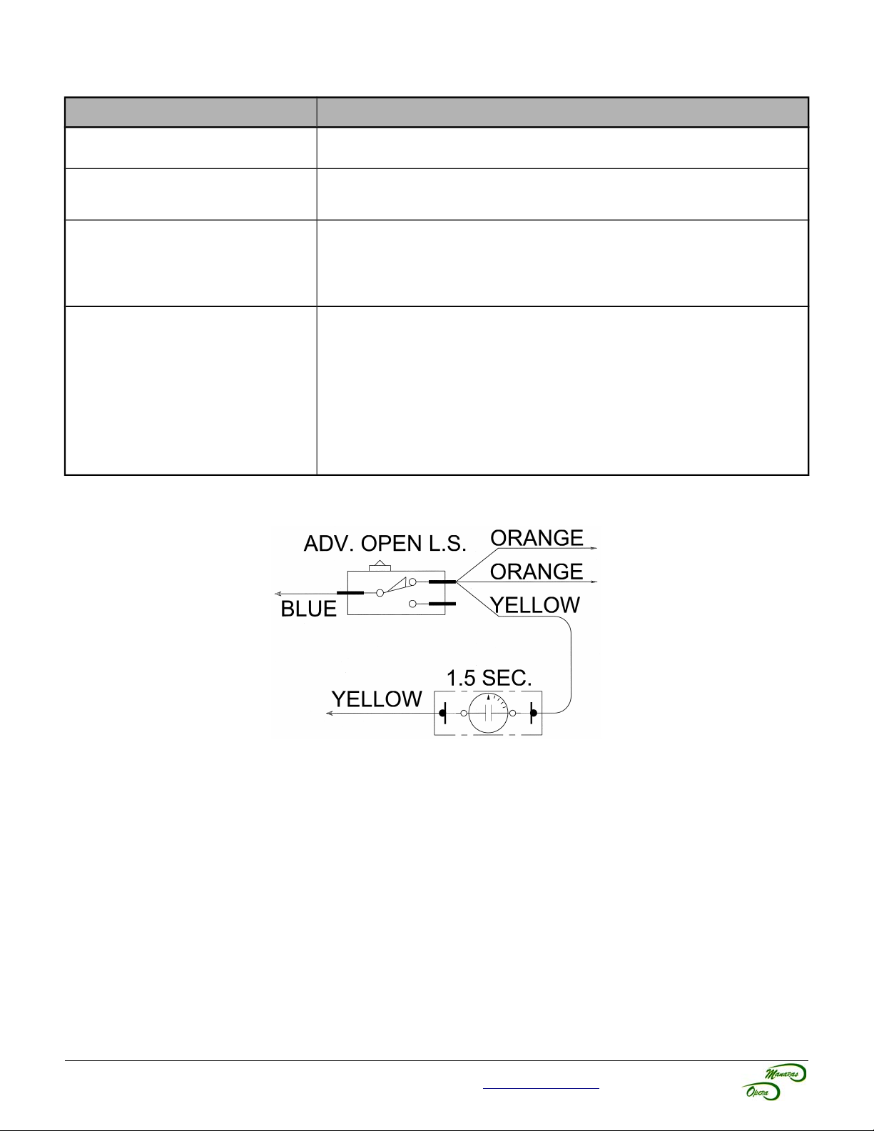
(refer to Figure 41 below)
Constant Pressure to Open and
Close – D1 Mode
1. Remove YELLOW wire from Adv. Open Limit Switch and cap it.
2. Remove BLUE wire from pin #4 on the Reversing Relay (RR) and cap it.
1. Remove YELLOW wire from Adv. Open Limit Switch.
2. Connect the YELLOW wire to one end of the Time Delay Module.
3. From the other end of the Time Delay Module, reconnect YELLOW wire
to the Adv. Open Limit Switch.
1. B2 Mode → C2 Mode:
◦ Move RED wire from terminal #7 → #5.
2. Constant Pressure to Open:
◦ Move GREY wire from terminal #3 → #4.
3. Wiring for Instant Stop:
◦ Remove YELLOW wire from Adv. Open Limit Switch and cap it.
◦ Remove BLUE wire from pin #4 on Reversing Relay (RR) and
cap it.
Figure 41 - Time Delay on Reverse
For technical support, please call 1-800-361-2260 or visit www.manaras.com for more information
Page 26
26
User Instructions
IMPORTANT SAFETY INSTRUCTIONS
WARNING
TO REDUCE THE RISK OF SEVERE INJURY OR
DEATH TO PERSONS:
1. READ AND FOLLOW ALL INSTRUCTIONS.
2. Never let children operate or play with door controls. Keep the remote control (where
provided) away from children.
3. Personnel should keep away from a door in motion and keep the moving door in sight
until it is completely closed or opened. NO ONE SHOULD CROSS THE PATH OF A
MOVING DOOR.
4. Test the door's safety features at least once a month. After adjusting either the force or
the limit of travel, retest the door operator's safety features. Failure to adjust the
operator properly may cause severe injury or death.
5. For products having a manual release, if possible, use the manual release only when
the door is closed. Use caution when using this release with the door open. Weak or
broken springs may cause the door to fall rapidly, causing severe injury or death.
6. KEEP DOORS PROPERLY OPERATING AND BALANCED. See Door Manufacturer’s
Owner Manual. An improperly operating or balanced door could cause severe injury or
death. Have trained door systems technician make repairs to cables, spring
assemblies and other hardware.
7. SAVE THESE INSTRUCTIONS.
IMPORTANT
For more information or for immediate assistance, please contact your local dealer.
NOTICE
• The installer should perform a demonstration of the operator and it's accessories (ex: push-button
station, radio control), external entrapment protection device and manual release for the end-user.
For instructions regarding the Hoist, Disconnect Mechanism and Emergency Egress, refer to the Installation
Instructions found in section 6.2, p.11.
For technical support, please call 1-800-361-2260 or visit www.manaras.com for more information
Page 27
1 Quick Fix Instructions
Table 7 - Basic Troubleshooting Guide ~ from floor level
Symptom Suggested Action Fix Problem
27
Door doesn't respond
to any command
Door doesn't respond
to “Close” or radio
commands
Door doesn't
respond to any radio
command
Chain hoist is in engaged position
(if applicable).
Disconnect chain is in engaged position
(if applicable).
“Stop” button is stuck. ➔ Press and release any “Stop” button.
No power supply. ➔ Verify the incoming power line from
Photo cells are not properly aligned or are
obstructed.
Loop is obstructed (presence of metal). ➔ Clear the obstruction.
No power supply. (transmitter light is OFF) ➔ Replace transmitter's battery.
Poor radio control range. ➔ Bring the radio transmitter closer to
Photo cells are not properly aligned or are
obstructed.
➔ Return the chain to its neutral position
(electrical mode). Refer to p.11 for further
details.
➔ Release tension from the disconnect
chain and secure the chain keeper. Refer
to p.11 for further details.
the main breaker, making sure it has not
tripped or blown a fuse.
➔ Clear the obstruction or re-align photo
cells.
the operator.
➔ Clear the obstruction or re-align photo
cells.
For technical support, please call 1-800-361-2260 or visit www.manaras.com for more information
Page 28
28
Maintenance Instructions
IMPORTANT SAFETY INSTRUCTIONS
WARNING
TO REDUCE THE RISK OF SEVERE INJURY OR
DEATH TO PERSONS:
• Inspections, service and repairs should be performed anytime a malfunction is observed
or suspected.
• Only qualified persons should perform maintenance on a door operator and all safety
precautions should be taken into consideration.
• When servicing, always disconnect operator from main power supply.
• KEEP DOORS PROPERLY OPERATED AND BALANCED.
• See Door Manufacturer’s Owner Manual. An improperly operated or balanced door can
cause severe injury or death. Have qualified door system technicians perform repairs to
cables, spring assemblies and other hardware.
1 Preventative Maintenance Schedule
1.1 Mechanical Inspection
The door area should always be kept clear of dirt, rocks or any other substances in order to insure proper operation.
Maintenance of the door operator should be performed according to the schedule in Table 8 and Table 9.
Table 8 - Mechanical Inspection Schedule (Part 1)
Time
Frame
Every
Month
Every
3 Months
Every
6 Months
• Test the door’s safety features.
• Verify the brake function (if applicable).
• After adjusting either the clutch or the limit's travel, retest the operator’s safety features.
• Verify gear reducer's oil level (if applicable).
• Verify and adjust the clutch if necessary.
• Lubricate all moving parts. Bushings are oil impregnated and are lubricated for life.
• Verify that all mechanical parts function properly.
• Inspect the V-belt and adjust or replace if necessary.
• Manually operate the door. If the door does not open or close freely, correct the cause of the
malfunction.
Inspection
For technical support, please call 1-800-361-2260 or visit www.manaras.com for more information
Page 29
Table 9 - Mechanical Inspection Schedule (Part 2)
29
Time
Frame
Once a
Year
• Run the operator a few cycles:
◦ Make sure that the door rollers are rolling smoothly on the track.
◦ Listen to the motor: The motor should hum quietly and smoothly.
◦ Verify that the limits operate quietly and smoothly: investigate any unusual noise.
• Verify that the mounting bolts are holding the unit securely.
• Inspect the unit for evidence of corrosion.
• Change the gear reducer's oil, at the very least, after every 2500 hours of operation or once a
year (if applicable).
Inspection
1.2 Electrical Inspection
It is recommended that the electrical maintenance inspections be performed at the same intervals as the mechanical
maintenance inspections.
Table 10 - Electrical Inspection
Time Frame Inspection
Inspect the unit for evidence of corrosion on electrical wires and connectors.
Inspect the wiring compartment and remove any dirt from the control units.
Verify all the grounding wires and terminals for corrosion. Be particularly careful to verify the
ground wires.
Verify the terminal strips to insure that all the screws are tightened.
Every Month
Verify that the pneumatic edge or other entrapment protection devices installed on the
operator are fully operational.
Verify the voltage at the input terminals while the operator is running. The voltage must not drop
more than 10% momentarily. If the voltage drop is too deep when running, the relays may
chatter and the contact points will wear prematurely and may eventually seize. Verify the power
terminals for corrosion.
Verify the current consumption of the unit with an amp-meter. The current value should be
consistent with the nameplate specifications. Investigate any anomaly.
For technical support, please call 1-800-361-2260 or visit www.manaras.com for more information
Page 30
30
4
3
2
1
5
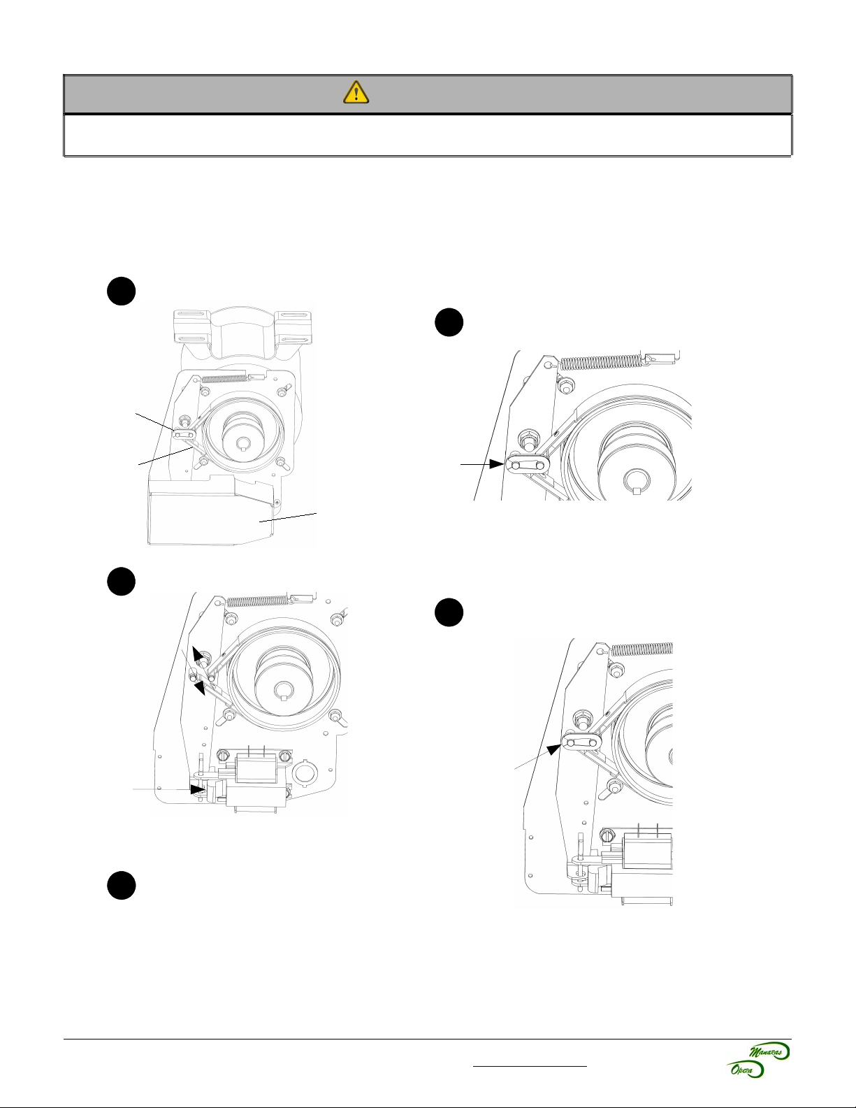
1.3 Band Brake Maintenance
WARNING
To reduce the risk of SEVERE INJURY or DEATH to persons:
• Be sure that the main power is OFF before performing any changes on the operator.
1.3.1 Changing a Brake Band
The brake band is preformed at the factory. Please insert the brake band carefully around the brake drum.
Remove solenoid cover
Remove link and used band brake
Link
Band
Brake
Solenoid Cover
Replace band brake
Push solenoid plunger to reduce tension when
removing or installing the band brake.
Push to
remove
Place the link
Be sure that the link is
securely fastened on
the two pins.
See brake adjustment
on next page
For technical support, please call 1-800-361-2260 or visit www.manaras.com for more information
Page 31
31
56342
1
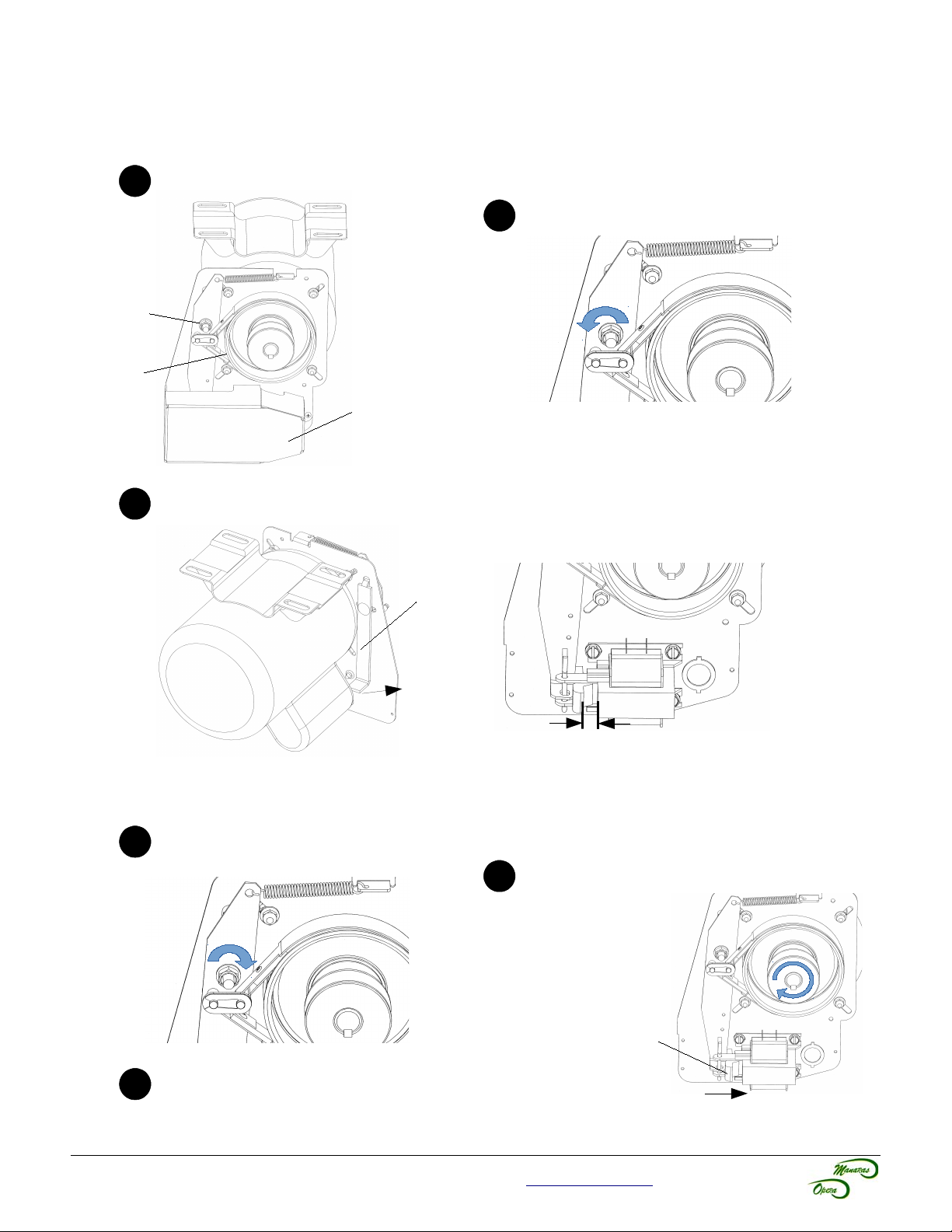
1.3.2 Brake Adjustment
The brake is factory set, however, after extensive use the brake may need to be adjusted.
Remove solenoid cover
Loosen pivot nut
Pivot Nut
Brake
Drum
Solenoid Cover
Adjust solenoid gap
Pull the lever to adjust the gap between
the plunger and solenoid body.
Tighten pivot nut
Recheck the gap
measurement.
Lever
Gap must be between 1/4''and 3/8''.
Check brake adjustment
Manually push the plunger onto
the solenoid body, and verify
that the brake drum rotates
easily by hand.
Plunger
Re-install solenoid cover
For technical support, please call 1-800-361-2260 or visit www.manaras.com for more information
Page 32
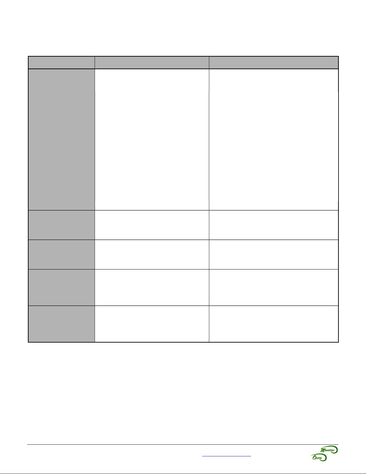
2 Troubleshooting Guide
Table 11 - Troubleshooting Guide – Part 1
Symptom Probable Cause Suggested Action
32
Door doesn't
respond to any
command
Door closes or by
itself, operator
doesn't shut off after
door is closed
Door opens by itself,
operator doesn't
shut off after door is
open
Door doesn't
respond to “Open”
command, but does
respond to “Close”
command
Door doesn't
respond to “Close”
command, but does
respond to “Open”
command
Chain hoist is in engaged position
(if applicable).
Disconnect chain is in engaged position
(if applicable).
“Stop” button is stuck. ➔ Press and release any “Stop” button.
Control station is not connected or is
wired incorrectly.
No power supply. ➔ Verify the incoming power line from the
Overload thermal protection has been
tripped.
Defective transformer. ➔ Verify and replace transformer.
Defective contactor. ➔ Verify and replace contactor.
Defective “Close” limit switch. ➔ Replace limit switch.
Defective contactor. ➔ Verify and replace contactor.
Defective “Open” limit switch. ➔ Replace limit switch.
Defective “Open” push-button or
“Open” limit switch.
Loose wire on “Open” push-button or
“Open” limit switch.
Defective “Close” push-button or
“Close” limit switch.
Loose wire on “Close” push-button or
“Close” limit switch.
➔ Return the chain to its neutral position
(electrical mode). Refer to p.11 for further
details.
➔ Release tension from the disconnect chain
and secure the chain keeper. Refer to p.11 for
further details.
➔ Verify and correct wiring.
main breaker, making sure it has not tripped
or blown a fuse.
➔ Reset overload protection:
1. Press reset button on side of unit for
1-phase or let the motor cool down for
3-phase.
2. Verify manual operation of the door.
➔ Replace push-button or limit switch.
➔ Verify and correct wiring.
➔ Replace push-button or limit switch.
➔ Verify and correct wiring.
For technical support, please call 1-800-361-2260 or visit www.manaras.com for more information
Page 33
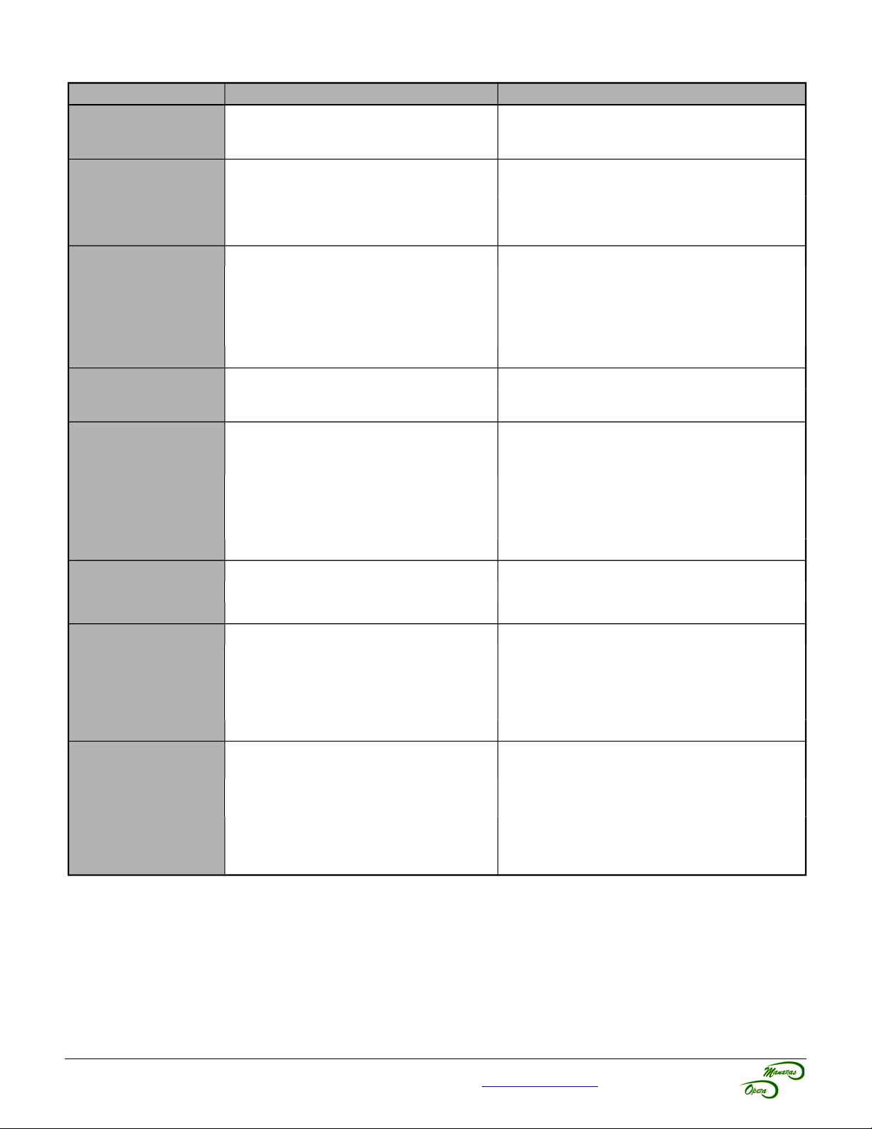
Table 12 - Troubleshooting Guide – Part 2
Symptom Probable Cause Suggested Action
“Stop” button
doesn’t stop the
Two 3-push button stations (or more)
are connected in parallel.
door
Door reverses to
fully open position
after the door closes
Defective “Advanced Close” limit
switch.
A “Open” command is being given. ➔ Verify “Open” push-button or any closing
and reaches the
floor
Mechanical door lock is engaged. ➔ Release the door lock.
Door doesn't open
or close, motor
hums or blows the
main breaker.
Door is jammed. ➔ Verify manual operation of door.
Brake doesn't release, if applicable. ➔ Verify and adjust brake tension.
Loose wire on solenoid brake, if
applicable.
Defective solenoid brake, if applicable ➔ Replace.
Motor hums when
“Open” or “Close”
Loose motor wires. ➔ Verify and correct wiring.
Defective capacitor. ➔ Replace.
buttons are pressed.
Defective limit switch. ➔ Operate limit switch manually while door is
Motor fails to shut
off at fully closed or
fully opened
positions
Limit cams are not adjusted. ➔ Verify and adjust.
Limit drive chain is broken. ➔ Replace.
Loose sprocket on limit shaft. ➔ Tighten set screw.
Limit shaft does not rotate. ➔ Verify and replace accordingly.
Sprocket key is missing. ➔ Replace.
Motor turns but door
does not move
Drive chain is broken. ➔ Replace.
Clutch is slipping. ➔ Adjust clutch to proper tension.
Loose drive or limit chain. ➔ Adjust chain to proper tension.
Limit switches do
not hold their
settings
Limit cam retaining bracket is not
engaging in the slots of the limit cams.
Limit cams are binding on shaft
threads.
Limit shaft has a slight “play”. ➔ Verify and adjust.
No power supply. (Transmitter light is
OFF)
Door doesn't
respond to any radio
command
Radio antenna is not properly
positioned.
Ambient radio, environmental or
building structure interference.
33
➔ Verify and correct wiring (Stop buttons in
series, only Open & Close in parallel).
➔ Verify and replace the limit switch.
device for short-circuit.
➔ Verify and correct wiring.
moving. If door does not stop, replace the
switch.
➔ Be sure it is engaged in slots of both
cams.
➔ Lubricate shaft threads. Limit cams should
turn freely.
➔ Replace transmitter's battery.
➔ Make sure antenna cable is not bent.
Cable should be passed through control box.
➔ Check connection of plug-in antenna. If
required add an external antenna (socket on
receiver available).
For technical support, please call 1-800-361-2260 or visit www.manaras.com for more information
Page 34
34
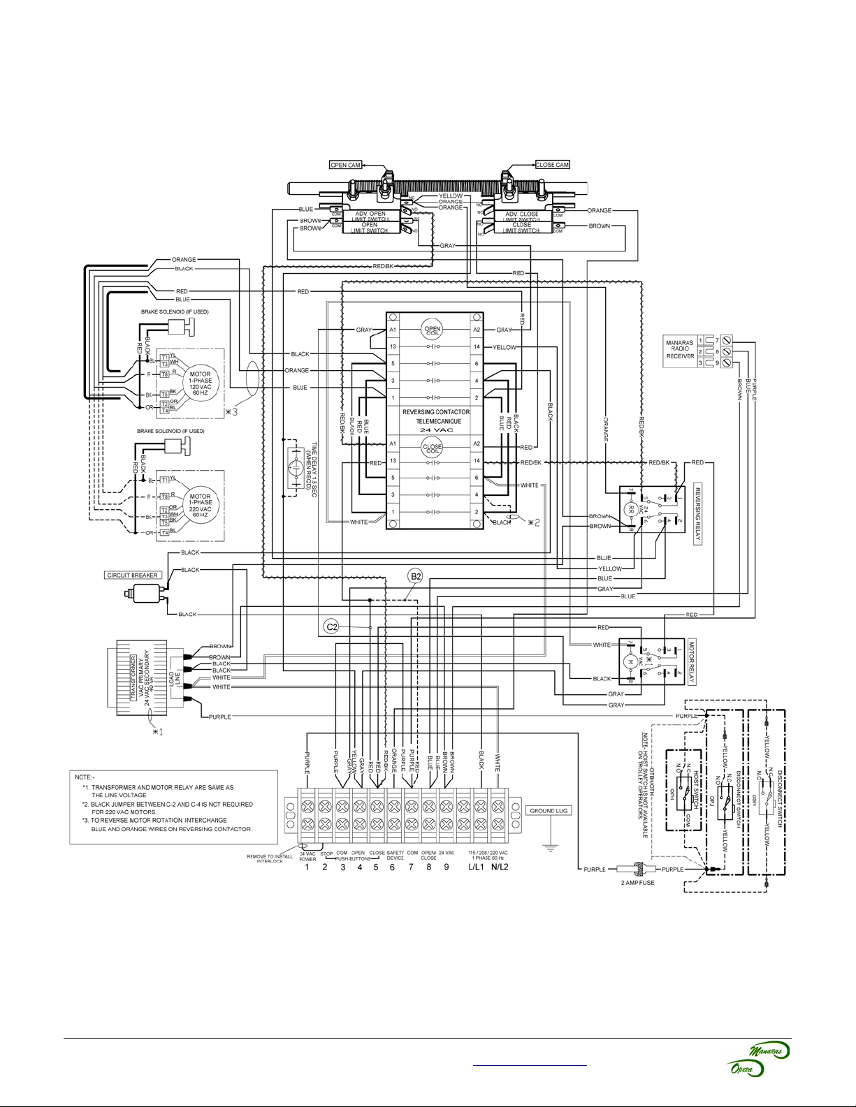
3 Electrical Drawings
3.1 1 Phase Operator – Hardwired Wiring
Figure 42 - EDWG11HWLC4401
For technical support, please call 1-800-361-2260 or visit www.manaras.com for more information
Page 35
35
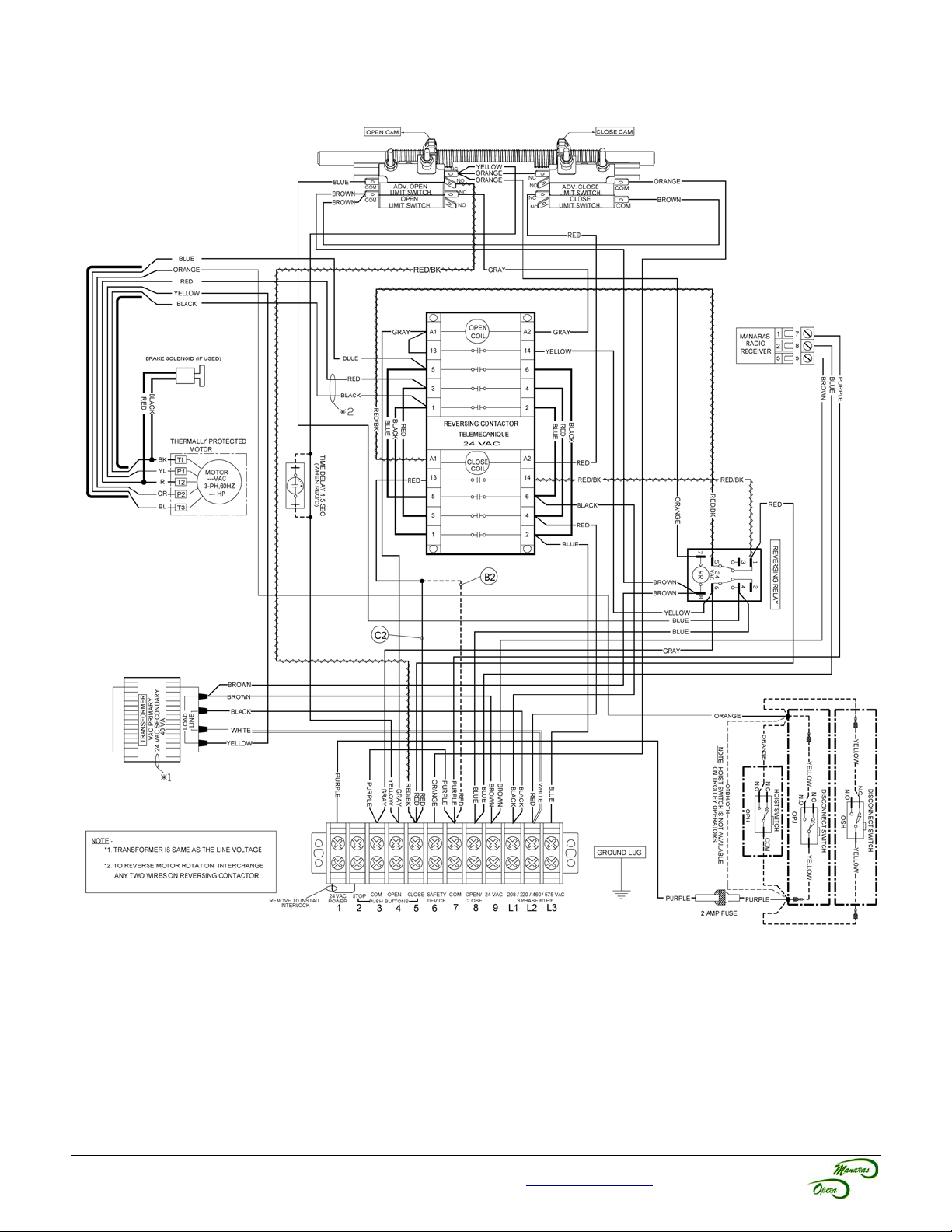
3.2 3 Phase Operator – Hardwired Wiring
Figure 43 - EDWG13HWLC4401
For technical support, please call 1-800-361-2260 or visit www.manaras.com for more information
Page 36
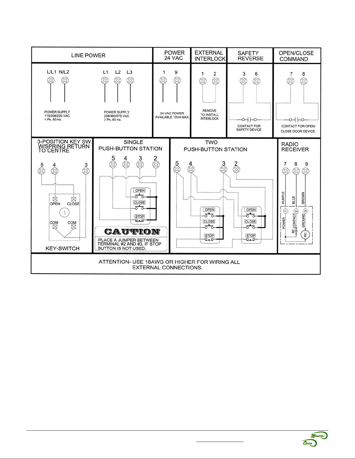
3.3 External Wiring – Hardwired
36
Figure 44 - External Wiring
For technical support, please call 1-800-361-2260 or visit www.manaras.com for more information
Page 37
37
4 Mechanical Exploded Views and Replacement Components
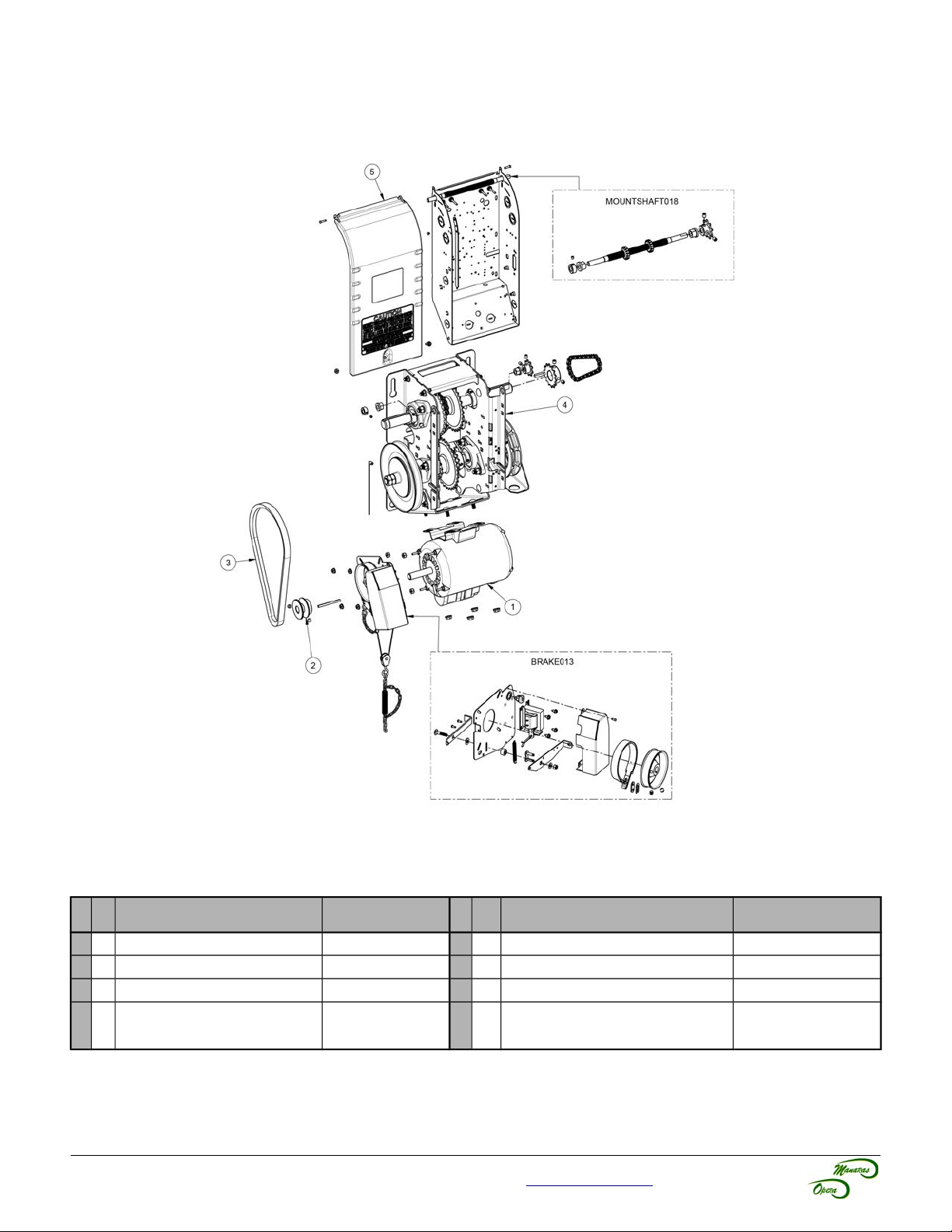
4.1 Opera Heavy-Duty Jackshaft General View
Figure 45 - Opera General Mechanical Exploded View
Table 13 - Opera General Replacement Components
No Qty Description
1 1 MOTOR SEE Table 20 5 1 OPERA CONTROL BOX COVER COVER047
2 1 MOTOR PULLEY 2.0 x 5/8 5L PULLEY014 1 OPERA LIMIT SHAFT KIT MOUNTSHAFT018
3 1 TYPE B, INSIDE LENGTH 29 VBELTB29 1 BRAKE ASSEMBLY KIT (#101-103) BRAKE013
4 1 SUB ASSY FRAME
Manaras-Opera
Part #
DEPENDING ON
MODEL, SEE TABLES
ON P.38, 39, 40, 41
No Qty Description
For technical support, please call 1-800-361-2260 or visit www.manaras.com for more information
Manaras-Opera
Part #
Page 38
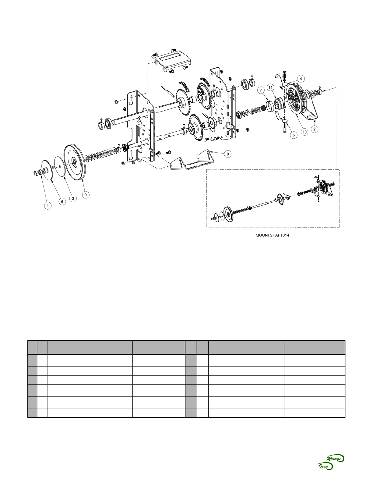
4.2 Opera-H
38
Figure 46 - Opera-H Mechanical Exploded View
Table 14 - Opera-H Replacement Components
No Qty Description
1
2 5/8-18 HEX JAM NUT ZP NUT013
2
1 CHAIN GUIDE OPERA GUIDE014
3
1 CL.PAD 5/8x4x0.125" CLUTCHPAD005
4
1 DISCONNECT SWITCH SHOE SHOE010
5
1 DISCONNECT SWITCH SHOE A SHOE009
6
1 OPERA CLUTCHPLATE CLUTCHPLATE006
Manaras-Opera
Part #
No Qty Description
7
8
9
10
11
OPERA DISCONNECT FRICTION
1
1 OPERA MOTOR PLATE PLATE078
1 PULLEY 7" x 5/8" 5L/B PULLEY020
PW ASSEMBLY (ROLLERS AND
1
SYNTHETIC DISCONNECT CAM
1
1 CLUTCH & HOIST SHAFT KIT MOUNTSHAFT014
BAND
CLIPS)
OPERA
Manaras-Opera
POCKETWHEEL007
Part #
SHOE011
CAM017
For technical support, please call 1-800-361-2260 or visit www.manaras.com for more information
Page 39
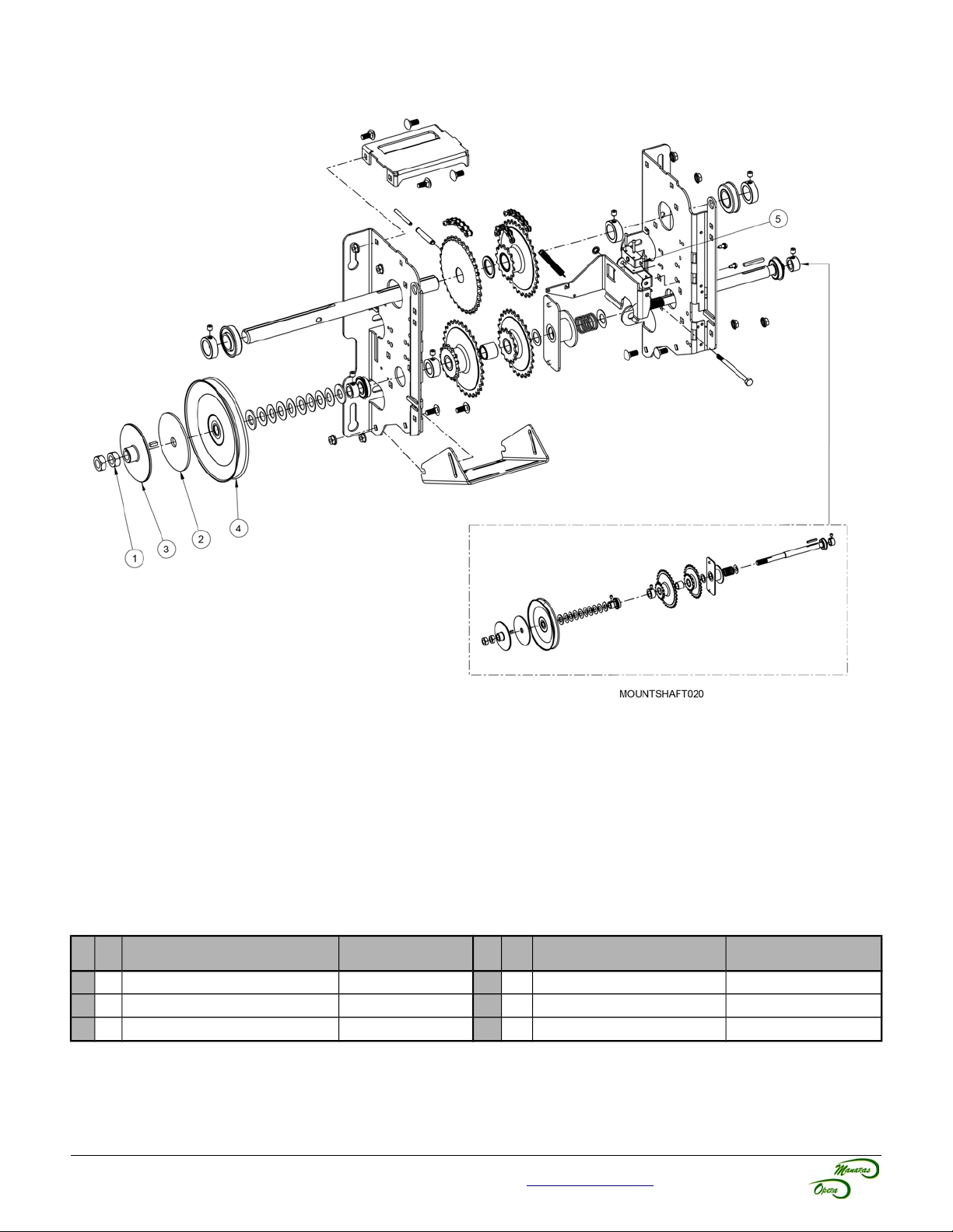
4.3 Opera-J
39
Figure 47 - Opera-J Mechanical Exploded View
Table 15 - Opera-J Replacement Components
No Qty Description
1
2 5/8-18 HEX JAM NUT ZP NUT013
2
1 CL.PAD 5/8x4x0.125" CLUTCHPAD005
3
1 OPERA CLUTCHPLATE CLUTCHPLATE006
For technical support, please call 1-800-361-2260 or visit www.manaras.com for more information
Manaras-Opera
Part #
No Qty Description
4
1 PULLEY 7" x 5/8" 5L/B PULLEY020
5
1 STD SINGLE CUT-OFF SWITCH LIMIT020
1 CLUTCH SHAFT KIT (OPJ) MOUNSHAFT020
Manaras-Opera
Part #
Page 40
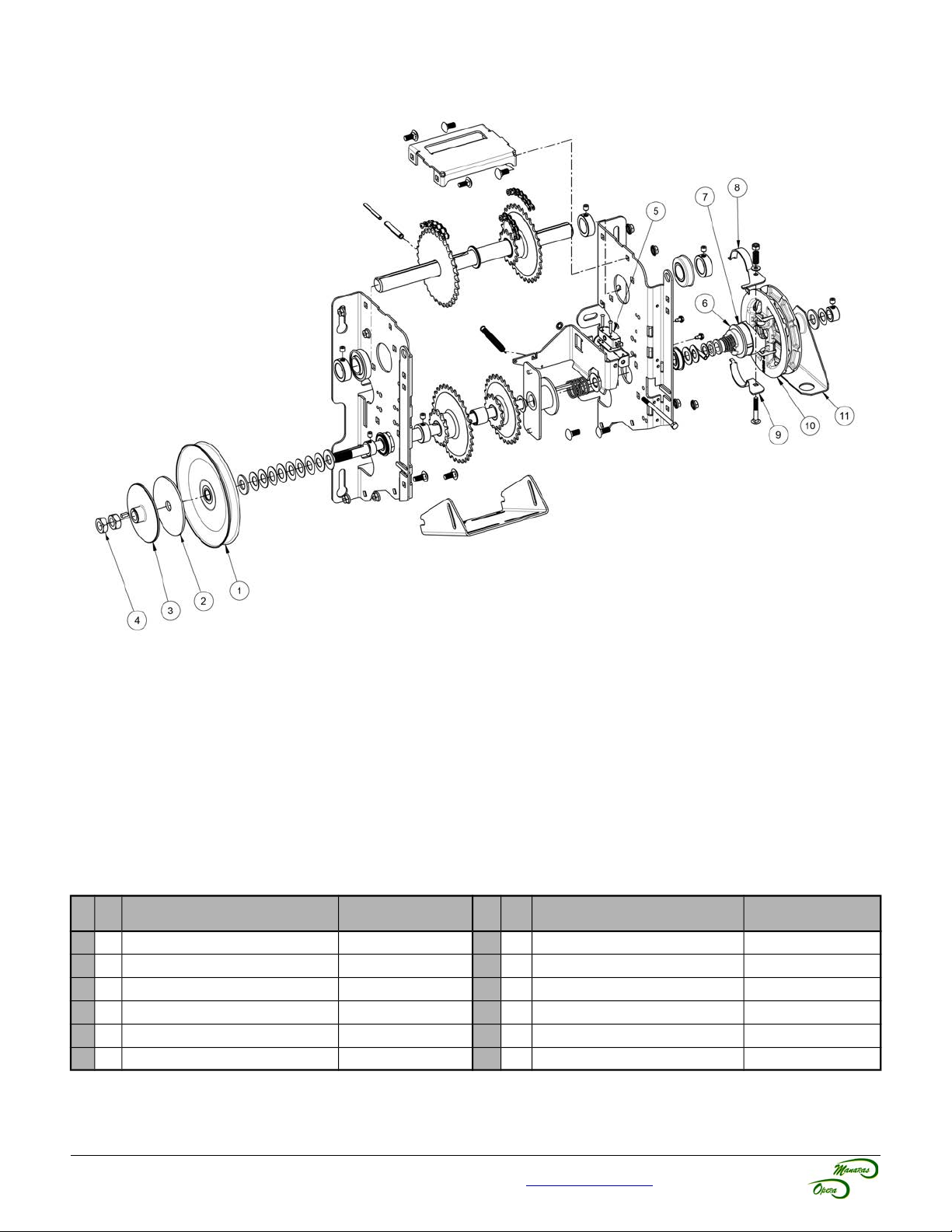
4.4 Opera-HJ
40
Figure 48 - Opera-HJ Mechanical Exploded View
Table 16 - Opera-HJ Replacement Components
No Qty Description
1
1 PULLEY 7" x 5/8" 5L/B PULLEY020
2
1 CL.PAD 5/8x4x0.125" CLUTCHPAD005
3
1 OPERA CLUTCHPLATE CLUTCHPLATE006
4
2 5/8-18 HEX JAM NUT ZP NUT013
5
1 STD SINGLE CUT-OFF SWITCH LIMIT020
6
1 SYNTHETIC DISCONNECT CAM OPERA CAM017
Manaras-Opera
Part #
No Qty Description
7
1 OPERA DISCONNECT FRICTION BAND SHOE011
8
1 DISCONNECT SWITCH SHOE SHOE010
9
1 DISCONNECT SWITCH SHOE A SHOE009
10
1 PW ASSEMBLY (ROLLERS AND CLIPS) POCKETWHEEL007
11
1 CHAIN GUIDE OPERA GUIDE014
Manaras-Opera
Part #
For technical support, please call 1-800-361-2260 or visit www.manaras.com for more information
Page 41
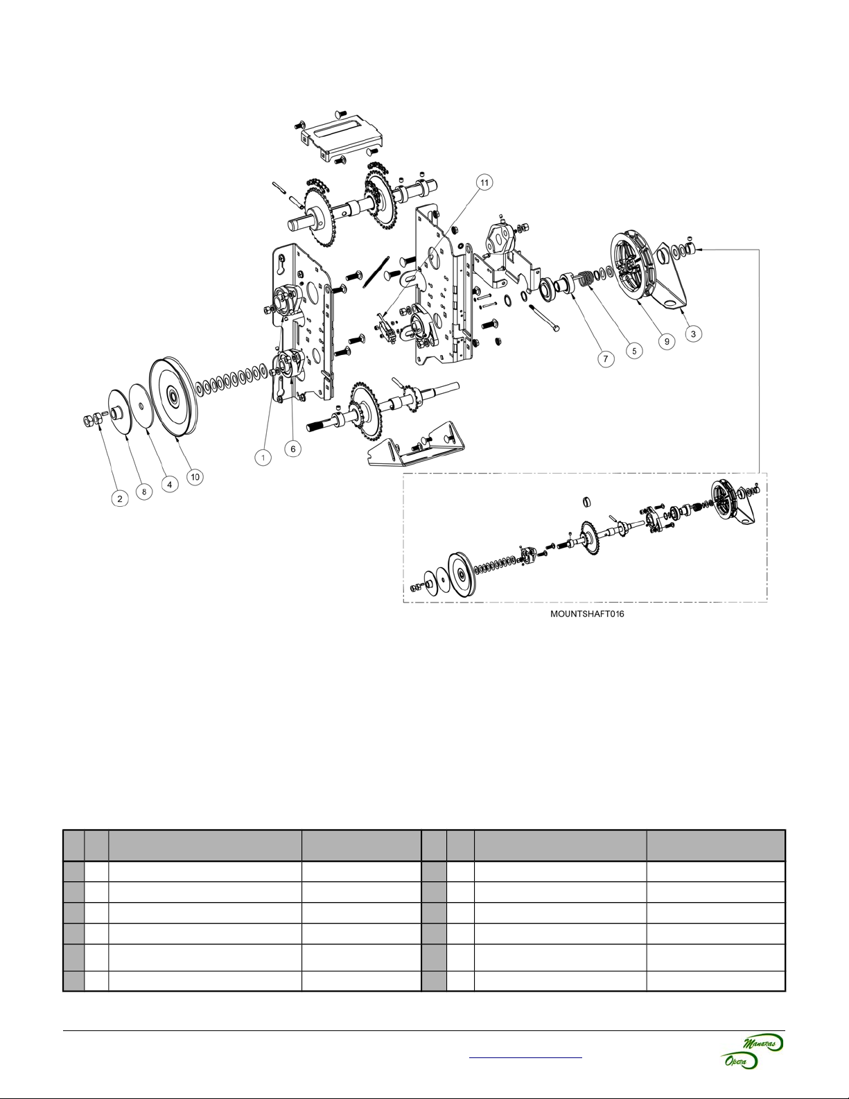
4.5 Opera-SH
41
Figure 49 - Opera-SH Mechanical Exploded View
Table 17 - Opera-SH Replacement Components
No Qty Description
1
2 1" ID 2-BOLT FLANGE BEARING BEARING012
2
2 5/8-18 HEX JAM NUT ZP NUT013
3
1 CHAIN GUIDE OPERA GUIDE014
4
1 CL.PAD 5/8x4x0.125" CLUTCHPAD005
5
1 COMP. SPRING DISC. OSH SPRING043
6
2 FLANGE PILLOW BLOCK 0,75 BEARING044
For technical support, please call 1-800-361-2260 or visit www.manaras.com for more information
Manaras-Opera
Part #
No Qty Description
7
1 MANUAL HOIST COUPLING COUPLING019
8
1 OPERA CLUTCHPLATE CLUTCHPLATE006
9
1 OPERA POCKETWHEEL POCKETWHEEL005
10
1 PULLEY 7" x 5/8" 5L/B PULLEY020
11
SNAP-ACT. SW.SPDT-LEVER
1
1 CLUTCH & HOIST SHAFT KIT MOUNTSHAFT016
"END BEND"
Manaras-Opera
Part #
LIMIT025B
Page 42
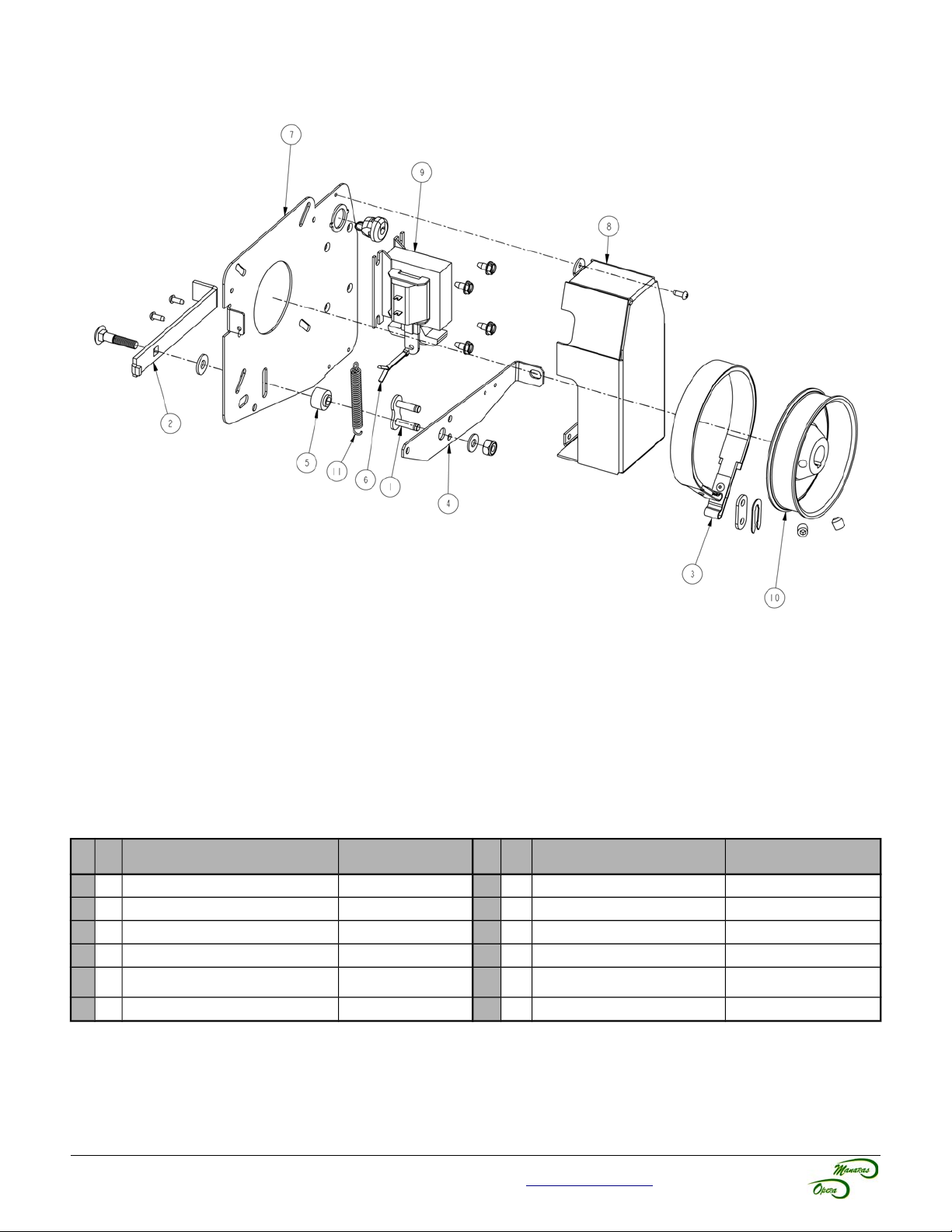
4.6 Opera Brake (BRAKE 013)
42
Figure 50 - BRAKE 013 Mechanical Exploded View
Table 18 - BRAKE 013 Replacement Components
No Qty Description
1
1 #50 CONNECTING LINK 50-1 LINK011
2
1 ADJUSTMENT BRAKE LEVER LEVER064
3
1 BRAKE BAND ASSEMBLY HEAVY DUTY BRAKEPART019
4
1 BRAKE LEVER LEVER065
5
1 BRAKE LEVER PIVOT BUSHING053
6
1 PIN COTTER 1/8 X 1-1/2 PIN001
Manaras-Opera
Part #
No Qty Description
7
1 PLATED BRAKE PLATE PLATE084
8
1 PLATED SOLENOID COVER COVER048
9 1 SOLENOID SEE Table 20
10
1 STEEL BRAKE DRUM ID 0.626 DRUM005
11
TROLLEY ARM DISCONNECT
1
SPRING
Manaras-Opera
Part #
SPRING026
For technical support, please call 1-800-361-2260 or visit www.manaras.com for more information
Page 43
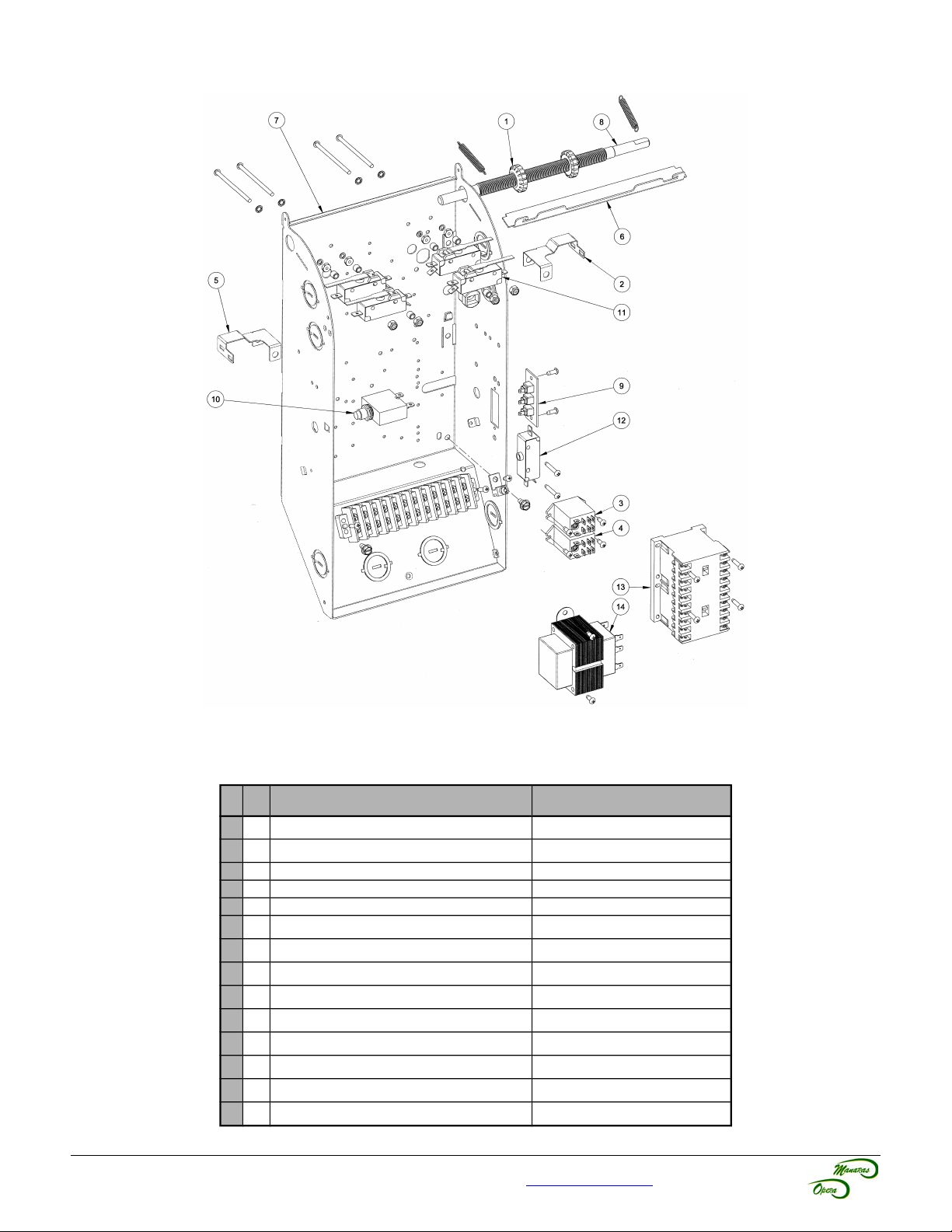
4.7 Opera Control Box - Hardwired
43
Figure 51 - Opera Control Box Hardwired
Table 19 - Control Box Replacement Components (CBOX032)
No Qty Description
1 2 CAM LIMIT OPERA CAM011
2 1 CLOSE LIMIT ACTUATOR LEVER092
3 1 DPDT 24V RELAY RELAY024
4 1 DPDT RELAY SEE Table 20
5 1 OPEN LIMIT ACTUATOR LEVER091
6 1 OPERA CBOX CAMPLATE CAMPLATE015
7 1 OPERA CONTROL BOX CBOX032
8 1 OPERA LIMIT SHAFT SHAFT103
9 1 RADIO CONTROL TERM STRIP TSTRIP005
10 1 RESET SEE Table 20
11 4 SNAP-ACT. SW.SPDT-LEVER FLAT 1" LIMIT021
12 1 STD SINGLE CUT-OFF SWITCH LIMIT020
13 1 TELEM. REVERS. CONT. 24V CONTACTOR044
14 1 TRANSFO TO 24V SEE Table 20
Manaras-Opera
Part #
For technical support, please call 1-800-361-2260 or visit www.manaras.com for more information
Page 44
44
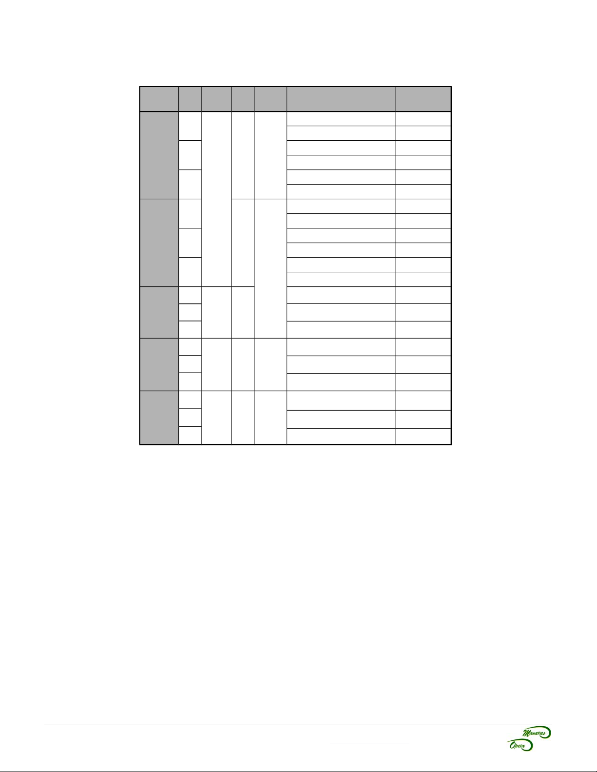
4.8 Replacement Motors, Transformers, Solenoids, Relays and Resets
Table 20 - Opera Replacement Motors, Transformers, Solenoids, Relays and Resets
According to Voltage/Phase and HP
V-PH HP Transfo.
1/2HP
120V - 1PH
230V - 1PH
208V - 3PH
460V - 3PH
3/4HP
1HP
1/2HP
3/4HP
1HP
1/2HP
3/4HP
1HP
1/2HP
3/4HP
1HP
1/2HP
Motor
Solenoid Description
Relay
MOTOR 1/2HP - 120V/230V - 1PH MOTOR254
1PH - 10 AMPS RESET RESET007
MOTOR 3/4HP - 120V/230V - 1PH MOTOR255
RELAY026
SOLENOID001
TRANSF143
RELAY027
SOLENOID002
N/A
TRANSF037
N/A
TRANSF088
SOLENOID003
1PH - 15 AMPS RESET RESET012
MOTOR 1HP - 120V/230V - 1PH MOTOR256
1PH - 17 AMPS RESET RESET014
MOTOR 1/2HP - 120V/230V - 1PH MOTOR254
1PH - 5 AMPS RESET RESET002
MOTOR 3/4HP - 120V/230V - 1PH MOTOR255
1PH - 87AMPS RESET RESET004
MOTOR 1HP - 120V/230V - 1PH MOTOR256
1PH - 9 AMPS RESET RESET006
MOTOR 1/2HP - 208V/460V - 3PH MOTOR271
MOTOR 3/4HP - 208V/460V - 3PH MOTOR273
MOTOR 1HP - 208V/460V - 3PH MOTOR275
MOTOR 1/2HP - 208V/460V - 3PH MOTOR271
MOTOR 3/4HP - 208V/460V - 3PH MOTOR273
MOTOR 1HP - 208V/460V - 3PH MOTOR275
MOTOR 1/2HP - 575V - 3PH MOTOR272
Manaras-Opera
Part #
575V - 3PH
3/4HP
1HP
N/A
TRANSF142
MOTOR 3/4HP - 575V - 3PH MOTOR274
MOTOR 1HP - 575V - 3PH MOTOR276
SOLENOID004
For technical support, please call 1-800-361-2260 or visit www.manaras.com for more information
Page 45

45
Notes
For technical support, please call 1-800-361-2260 or visit www.manaras.com for more information
Page 46

46
Notes
For technical support, please call 1-800-361-2260 or visit www.manaras.com for more information
Page 47

47
Warranty
Manaras-Opera warrants its operators to be free from defects in material and workmanship under normal and proper
use for a period of two years from date of invoice, unless otherwise stated. Mechanical, electrical and electronic
accessories are warranted for one year from date of invoice, unless otherwise stated. Wearing parts such as clutch
pads, v-belts, and brake bands are excluded from warranty.
Manaras-Opera’s only obligation shall be to repair or replace defective equipment which does not conform to the
warranty. Manaras-Opera shall not be liable for any injury, loss or damage, direct or consequential, arising out of the
inability to use the equipment. Before using, Buyer and/or the ultimate User shall determine the suitability of the
product for its intended use, and User assumes all risks and liability in connection therewith. The foregoing may not
be changed except by an Agreement signed by an authorized representative of Manaras-Opera.
The articles that are replaced pursuant to the terms of this warranty shall be retained by Manaras-Opera, and the
User is responsible for any freight costs relating to repair or replacement.
The foregoing warranty is exclusive and in lieu of all other warranties of quality, whether written, oral or implied
(including any other warranty of merchantability or fitness for purpose).
The following are exclusions from warranty:
• If usage, product modification, adaptation or installation are not in accordance with our installation and
operating instructions.
• If the product has been opened, dismantled or returned with clear evidence of abuse or other damage.
• If our written specifications are not properly applied by the Buyer when selecting the equipment.
• If our written instructions for installation and wiring of the electrical connections have not been followed.
• If our equipment has been used to perform functions other than the functions it was designed to handle.
• If Manaras-Opera equipment is used with electrical accessories (switches, relays, etc.) that have not been
previously approved in writing by the Manaras-Opera Engineering Department.
• If electrical accessories and other components have been used in disregard of the basic wiring diagram for
which they were designed.
All costs related to installation and re-installation of the Manaras-Opera equipment covered by this warranty are not
the responsibility of Manaras-Opera. Manaras-Opera will not be responsible for any consequential damages following
installation procedures performed by the Buyer or the User. If the Buyer resells any Manaras-Opera products to
another Buyer or User, it shall include all of the terms and provisions of this warranty in such resale. Manaras-Opera’s
responsibility to any such Third Party shall be no greater than Manaras-Opera’s responsibility under the warranty to
the original Buyer.
Returns
No returns will be accepted without prior written authorization by Manaras-Opera. All returns must be accompanied by
a Return Authorization Number issued by Manaras-Opera, and all unauthorized returns will be refused. The return
shipment is to be freight prepaid by the Buyer, and under no circumstances shall the Buyer deduct the value of the
returned merchandise from any remittance due. A restocking fee of 15% of the Manaras-Opera sale price will be
charged for all returns not covered under warranty.
For technical support, please call 1-800-361-2260 or visit www.manaras.com for more information
Page 48
Reg. T.M. of 9141-0720 Québec Inc.
BOOK1419 REV 3 – 2017/03/24
 Loading...