

Page 1
MV37 Halifax - plan 1
Tavola n. 1
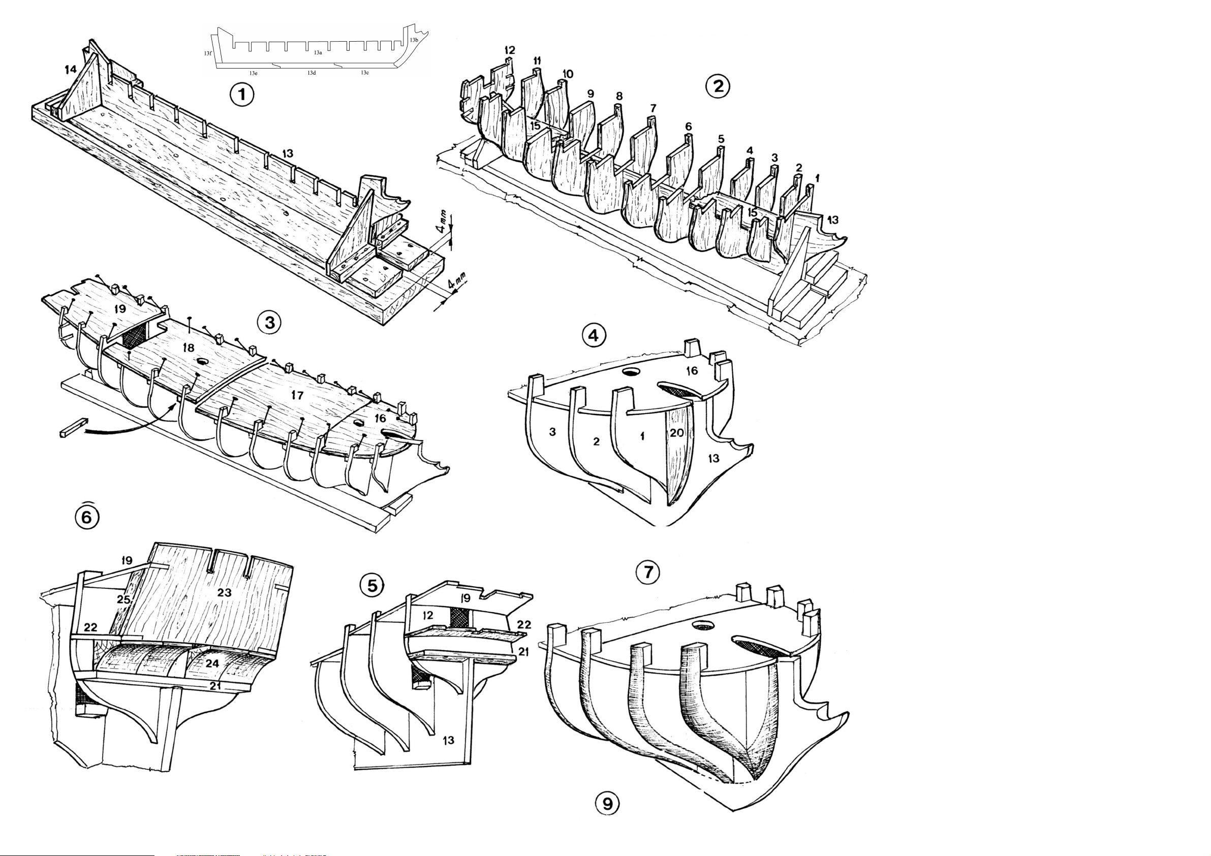
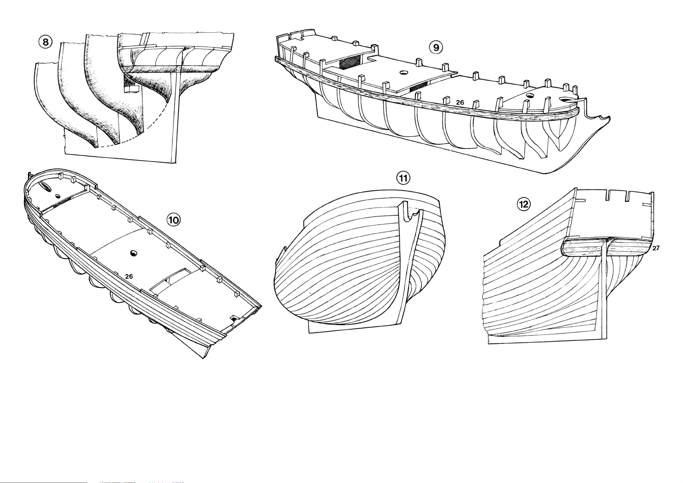
1) Fissare su di una tavoletta ben plana, spessa clrca 15 mm., 2 llstelll o strlsce di compénsalo da 4
mm. di spcssorc, dlstantl Ira loro 4 mm, , ln modo che vi si possa ln-caslrare la chlglla 13 e cho essa
vi rfmanga ln poslzlone rettillnea e vertlcale. Alio seo po di evitare ognl svergolamento della
struttura, flssare con chlodl sulla tavoletta le squndrette 14 appogglate contro l flanchl della chlglla,
come indícalo nella flg. 1, Monta re, senza incollare. le ordinntc I,., 12 ne¡ rlspettlvi Incastrl sulla
chlglla 13, montare II falso ponte 15 ¡I guale deve appogglare esattamente sul fondo del vano sulle
ordlnate e sulla chlglla. Montare provvlsorlamente, fermnndoll con spllll, la coperta di prua 16, la
coperta céntrale 17, II mezzo ponte 18 e la coperta 19 del cassero, Durante II montagylo assicurarsl
che nessuna delle varié partí vada a forzare nel rlspettlvi Incastrl, al contrario é preferlbllc che si
abbla un leggero gloco. Controllare I 'all Ineamento della strut tura: osservaridola frontalmente, le
linee del pontl devono presentarsl Incurvate e su di-versl plañí, ma esattamente paralIele tra loro.
Eventuall correzlonl si possono apporta-re rltoccando leggermente gil Incastrl. Quando si é slcurl
che, osservando la struttura da diverse angolazionl, tutte le linee hanno un andamento corretto,
smontare completamente e rlcomlnclare II montagglo Incollando le ordlnate 1...12 e II falso ponte
15 secón do l'ordíne numérico. Controllare ancora che non vi siano svergolature e che le ordlnate,
guardando la struttura dall'alto, formino un angolo retto con la chlglla (fig. 2),
2) Incastrare a fondo sulla struttura e Incollare i settori 16, l 7, 18 e 19 che formano la coperta
completa, fermnndoll con spllli plantatl provvlsoriamente al centro e ai lati, ln corrIspondenza degli
Incastrl con le ordinatej rlnforzare gil incollaggi sotto la coperta, Incollando eventualmente del
pezzettf di listello (flg. 3).
3) Incollare a prua sul flanchl della chlglia e contro l'ordlnata 1, gil appoygl 20 per II fasclame (flg. 4).
Incastrare e Incollare dietro l'ordlnata 12 l'appogglo 21 del fasclame e la base 22 del lo specchio di
poppa (fig.5). Incollare lospecchio di poppa 23 incastran do negll apposltl alloggiamentl le sporgenze
della coperta19 e della base 22$sotto questa e sopra l'appogglo21, IncollareI blocchettl di raccordo
24. Al fine di seguiré la curvatu ra della base, & opportuno tagliare II blocchetto 24 ln 4 settori,
Incollandone 2 per parte, lasclando al centro un vano per' II passaygio del timone. Senipre per
l'appogglo a po£ pa del fasclame, Incollare i llstelll 25 sul lato anteriore dello specchio di poppa 23
(flg. 6).
4) Prepnrazione della struttura per il montaggio del primo fasclame. Aggiustare le ordlnate di prua e
i relativi appoggl 20 asportando lo spigolo anteriore del le ordinate, senza peró toccare II profilo
origínale corrIspondente alio spigolo posteriore. Ripetere lo stes so lavoro sulle ordlnate di p oppa:
ora ó lo spigolo posteriore che va asportato, tenendo presente che la parte bassa delle ultime 2
ordinate & smussata ln maniera accentuata, da to cheln questa parte dello scafo le linee di raccordo
con la chlglla sono molto affinate, mentre sotto lo specchio di poppa II fasciame prende una
curvatura molto stretta (figg. 7 f>8). Controllare II corretto andamento delle linee del fasciame
appoggiando un listello sulle ordinate ln diverse poslz lonl. Anche I piani lateral! del blocchetti 24
vanno aggiusta ti, dando loro unaincllnazlone corr Ispondente al naturale prosegulmento del profilo
del-l'ordinata 12.
5) II fasciame & costituito da 2 stratl di llstelll: il primo di legno tenero spesso 1,5 mm., II secondo
formato da llstelll plü strettl e sottili, di legno pregiato e di diversl colorí. Prima di venire messl ln
opera I listelli vanno lasciati a bagno per clrca mezz'ora al fine di renderli flessiblll, vengono poi
montati uno per volta alternativamente su un flanco e sull'altro della struttura, cosí da non
provocare deformazloni dello scafo, dovute alia tensione dei listelliman manoche si asclugano. Oltre
che sulleordinate I listelli vannoIncollatl tra loro e fermati con chlodinl piantati solo in parte,ln mo(b
da poterll togliere a fasclatura ultlmata. Prima <11 incollare un listello, controllare, appoggiandolo
sulle or dinate, che l'andamenlo sia rcgolare: puó accadere che qualche ordinata "manchi" o sia
abbondnnte; nel primo caso correggere inserendo sotto il listello del pezzettl di listello sottile, ¡n
caso contrario limare I'ordinata.
6) Primo fasciame. Montare il primo listello 26 col lato superiore a filo della linea supe rlore dolía
coperta céntrale 1 7. Incollare un secondo listello Intero sopra II primo, quin di completare (I
rlvestimento della parte superiore con nftrl llstelll, lasclando che questl superlno di qualche
millimetro le estremita delle ordlnate. SI noti che a prua II rlvestl-inento ó formato da 2 listelli che
girano nttorno alia prua senza essore interrottl o terml nano a clrca 8 mm. oltre il gradino esistente
tra la coperta di prua ela coperta céntralo (fig. 9-10). Completare la parte interiore del rIvestimentoJ
ora i listelli vanno rnstrema ti verso prua a partiré dalle ordlnate 4-5. ln altre parole I listelli vanno
progresslva^-mente ridotti in larghezza fino ad avere l'estremlta che appoyyla contro la chiglia, non
piu larga di 3 mm. Infatti, partendo dal centro verso la prua, le ordinate hanno uno svl-luppo sempre
minore, pur dovendo conteneré sempre lo stesso numero di listelli, da ció la necessita di rldurne la
larghezza. Apoppa i listelli non vanno rastremati poiché il fasclame prosegueanche sotto le ordinate
e terminadi piatto sullachlglia (fig. 11-12).Togliere tuttiI chiodini ellsciare la superficie delfasciame
con carta velrata a grana grossa avvolta su un pezzo di legno piano o curvo, secondo 1a posizione
dello scafo da a99Íustare. Se si riscontra qualche avvallamento, riemplre con stucco per legno e llvel
lare. A poppa, I listelli che appoggiano sulla chiglia, vanno agglustati riducendone lo spessorc fino a
zero, cosí da avere una superficie chiglia/fasciame senza soluzlone di continuitá. Aggiustare tutto lo
specchio di poppa e rivestire i blocchetti di raccordo 24 col listelli 27 posti in senso orlzzontale. Non
toccare, per ora, la parte superiore del fasciame.
Designer: Luigi Volonte
Page 2
Designer: Luigi Volonte
MV37 Halifax - plan 1
Table No. 1
1) Fix on a flat board, 15 mm thick, 2 laths or plywood strips 4 mm thick, at a distance of 4 mm from each other, so as to fit in the keel I 3 in a straight and upright position.
In order to avoid any possible warping of the structure, fix with nails onto the board the small squares 14 leaning against the keel sides, as Indicated In fig, I, Fit the frames 1,,, 12 in the respective grooves on the keel 13, without glueing them, assemble the false deck 15 which must lean exactly on the bottom of the space on the frames and on the keel.
Assemble provisionally the fore deck 16, the central deck 17, the half-deck 18 and the dock 19 of Ihe quarter-deck, fixing them with pins. During the assembly, make sure that none of the various parts forces in the respective grooves, on the contrary it is advisable to have a slight play. Check the alignment of the structure: facing It, the deck lines must be
bent and must lie on different planes, but exactly parallel to each other. Possible small corrections can bo made retouching slightly the grooves. When you are sure that, looking at the structure from various sides, all the lines are correct, dismountcompletely and start again the assembly glueing the frames 1,,, 12 andthe false deck 15 following the numerical
order. Care must bo taken that there are no warpings and that the frames, looking down on the structure, form a right angle with the keel (fig, 2),
2) Fit tightly on the structure and glue the sectors 16, 17, 18 and 19 forming the complete dock and fix them with pins driven provisionally In the middle and at the sides, in correspondence of the grooves with the frames; strengthen the glueings under the deck, glueing, if that is the case, pieces of strip (fig, 3),
3) Glue the supports 20 for the planking afore, on the hull sides and against the frame 1 (fig, 4), I It and glue behind the frame 12 the support 21 of the planking and the base 22 of the transom (fig. 5). Glue the transom 23 fitting In the special grooves the protrusions of the deck 19 and of the base 22; glue the connection blocs 24 under the base andón the
support 21. In order to follow the bending of the base it is advisable to cut the block 24 into 4 sectors and to glue 2 of them on each side, leaving in the middle an empty space for the rudder. Glue the strips 25 on the fore side of the trensom 23 for the support of the planking astern.
4) Preparation of the structure for the assembly of the first planking. Adjust the fore frames and the relative supports 20 trimming the fore edge of the frames without touching the original profile corresponding to the back edge. Repeat the same operation on the stern frames: now It is Ihe back edge that must be trimmed off. Care must be taken that the
low part of the Inst 2 frames must be strongly chamfered because in this part of the hull, the connection lines with the keel are very thin, while under the transom the plan-king assumes a very narrow bending (ficj, 7 and 8), Check that the lines of the planking are regular, laying a strip on the frames in various positions. The side surfaces of the blocks 24
must be adjusted too, giving them a bonding, which must be the natural continuation of the profile of the frame 12.
5) The planking consists in two layers of strips: the first of soft wood 1, 5 »rim thick, the second made of narrower and thinner strips, of precious wood and different colours. Before being applied the strips must be soaked for about half an hour. This will make them more flexible. They must then be applied one at a lime, alternatively on one side and on the
oilier of the structure, so as to avoid any possible warping of the hull, caused by the tension of the strips while they got dry. Besides being glued onto the frames, the strips must be glued to each other' and fastened with little nails only partially driven In, so as to take them out when the sheathing is over. Before glueing a strip check Its regular line, laying it
on the frames; should a frame be too narrow or too large, insert some pieces of thin lath under the strip, or file the frame.
6) First planking. Glue the first strip 26 with the upper side at the edge of the upper line of the central deck 17. Glue a second entire strip on the first one, then complete the sheathing of the upper deck with other strips, letting them stick some millimetres out of the frames. Take care that the sheathing on the prow consists of 2 strips turning around the
prow without being broken off and they stop about 8 mm beyond the step existing between the prow deck and the central deck (fig. 9 «and 10). Complete the lower part of the sheathing; now the strips must be chamfered towards the prow starting from the frames 4-5. In other words the strips must be progressively reduced in width till the end leaning
against the keel is 3 mm wide. In fact, starting from the middle towards the prow the frames get narrower and narrower though they must always contain the same number of strips. It is therefore necessary to reduce their width. Astern the strips must not be chamfered because the planking goes on under the frames too and ends flat on the keel (fig. I 1-
12). Remove all thenails and sand the surface of the planking with rough-grained sandpaper rolled around a flat or curved piece of wood, according to the position of the hull to be adjusted. In case of hollows, fill them with putty and level. At stern the strips leaning on the keel must be adjusted reducing their thickness to zero, so as to have an uninterrupted
surface keel/planking. Adjust the whole transom and sheathe the connection blocks 24 with the strips 27 placed horizontally. Do not touch, for the time being, the upper part of the planking.
Page 3
Table n. 1
1) Fixer sur une tablette bien plane, de 15 mm d’épaisseur, 2 lattes ou bandes de contreplaqué de 4 mm d’épaisseur, à une distance de 4 mm l'une de l’autre, de façon que la
quille 13 puisse être encastrée en position rectiligne et verticale. Afin d'éviter tout gauchissement de la structure, fixer avec des clous sur la tablette les équerres 14, appuyées
contre les flancs de la quille, comme indiqué sur la figure |. Monter les couples1... 12 dans les emboîtements respectifs, sans lescoller, monter lefaux pont 15 qui doit s’appuyer
exactement sur le fond des couples et sur la quille. Monter provisoirement le pont de proue 16, le pont central 17, le demi-pont 18 et le pont 19 du gaillard d'arrière et les fixer
avec des épingles. Pendant le montage s'assurer qu'aucune des différentes parties ne force dans les emboîtements respectifs, au contraire il est préférable qu'il y ait un certain
jeu. Contrôler l'alignement de la structure: en l'observant de front, les lignes des ponts doivent se présenter courbées et sur des plan'i différents, mais exactement parallèles
entre elles. D'éventuelles petites corrections pourront être effectuées en retouchant légèrement les emboîtements. Quand on est sûr que, observant la structure de différents
côtés, toutes les lignes ont une allure correcte, démonter complètement et recommencer le montage collant les couples I... 12 et le faux pont 15 selon l'ordre numérique.
Contrôler' encore qu'il n'y ait aucun gauchissement et que, regardant la structure d'en haut, les couples forment un angle droit avec la quille (fig. 2).
2) Encastrer à fond sur la structure et coller les secteurs 16, 17, 18 et 19 formant le pont complet, les fixant avec des épingles plantées provisoirement au centre et aux cotés,
en correspondance des emboîtements avec les couples; renforcer les collages sous le pont en collant éventuellement des pièces de laite (fig. 3).
3) Coller à proue sur les côtés de la quille et contre le couple 1, les appuis 20 pour le bordé (fig. 4), Encastrer et coller derrière le couple 12 l'appui 21 du bordé et la base 22 du
miroir de poupe (fig. 5). Coller le miroir de poupe 23, encastrant dans les logements spéciaux les saillies du pont 19 et de la base22; sous celle-ci et sur l'appui 21, coller les blocs
de raccordement 24. Afin de suivre la courbure de la base, il est con-seillable de couper le bloc 24 en 4 secteurs, d'en coller 2 sur chaque côté, laissant au milieu un espace pour
le passage du gouvernail. Coller les lattes 25 sur le côté antérieure *du miroir de poupe 23, pour l'appui a poupe du lx>rdé (fig. 6).
4) Préparation de la structure pour le montage du premier bordé. Ajuster les couples de proue et les appuis relatifs 20 enlevant l'arête antérieure des couples, sans toucher le
profil original correspondant à l'arête postérieure. Répéter le même travail sur les couples de poupe: maintenant c'est l'arête postérieur qui doit être enlevée, tenant compte
que la partie bosse de ces 2 derniers ccuples est arrondie d'une façon accentuée vu que dans cette partie de la coque les lignes de raccordement avec la quille sont très affinées,
tandis quo sous lo miroir do poupe le bordé prend une courbure très étroite (fig. 7 et 8), Contrôler l'alignement correct des lignes du bordé appuyant une latte sur les couples
en différents positions. Les plans latéraux des blocs 24 aussi doivent être ajustés, avec une inclination qui correspond à la continuation naturelle du profil du couple 12.
5) Le bordé est formé de 2 couches de lattes: la première de bois tendre épais de 1, 5 mm, la deuxième formée de lattes plus étroites et subtiles, de bois précieux de différents
couleurs. Avant de les appliquer, faire tremper les lattes pour une demi-heure afin de les rendre plus flexibles; elles doivent ensuite être montées une a la fois alternativement
sur un flanc et l'autre de la structure, de façon à ne provoquer aucune déformation de la coque, due à la tension des lattes à mesure qu'elles sèchent. Outre que sur les couples,
les lattes doivent être collées entre elles-mêmes et fixées avec de petits clous plantés seulement en partie, de façon à pouvoir les enlever lorsque le bordé est achevé. Avant
décoller' une latte, contrôler, en l'appuyant sur les couples, que sa ligne soit régulière; il peut arriver que quelque couple soit trop étroit ou trop large; il faudra dans le premier
cas corriger Insérant sous la latte des pièces de latte subtile, au cas contraire limer le couple.
6)Premier bordé. Monter la première latte 26 avec le côté supérieur au fil de la ligne supérieure du pont central 17. Coller une seconde latte entière sur la première, ensuite
compléter le doublage de la partie supérieur«avec d'autres lattes, laissant que celles-ci dépassent de quelques millimètres les extrémités des couples. Il faut noter que, à proue,
le doublage est formé de 2 lattes qui tournent autour de la proue sans être interrompues et se terminent 8 mm environ au-delà de la marche entre ie pont de proue et le pont*
cen tral (fig. 9-10). Compléter la partie inférieure du doublage ; maintenant la largeur des lattes doit être réduite à partir des couples 4-5. En d'autres mots les lattes doivent
être progressivement réduites en largeur jusqu'à avoir l'extrémité appuyée contre la quille, pas plus large de 3 mm. En effet, partant du centre vers la proue, les couples ont un
développement toujours inférieur, bien qu'ils doivent contenir toujours la même quantité de lattes, d'où la nécessité d'en réduire la largeur, A poupe les lattes ne doivent pas
être réduitespuisque le bordé continue même sous les couples et finit à plat sur la quille (fig. 11-12). Enlever tous les clous et niveler la surface du bordé avec papier de verre à
gros grain enroulé sur une pièce de bois plan ou courbe, selon la position de la coque à ajuster. Si l'on trouve quelque enfoncement, remplir avec du stuc pour bois et niveler.
A poupe, les lattes appuyées sur la quille, doivent être ajustées réduisant l'épaisseur jusqu'à zéro, de façon à avoir une surface quille/bordé sans solution de continuité.
Ajuster tout le miroir de poupe et doubler les blocs de raccord ement 24 avec les lottes 27 placées en sens horizontal. Ne pas toucher, pour le moment, la partie supérieure du
bordé.
MV37 Halifax - plan 1
Tafel Nr. 1
1) Auf einer glatten Holztafel, 15 mm dick, 2 Leisten 4 mm und voneinander 4 mm entfernt fixieren, so dass man den Kiel 13 gerade und senkrecht elnsetzen kann.
Damit man eine Änderung der Struktur vermeidet, auf die Tafel die Dreiecke 14, an die Selten des Kiels wie auf dem Bild I mit Nägeln fixieren. Ohne zu kleben, die
Spanten 1... 12 in die best Im mten Zapten auf den Kiel 13 elnsetzen, die falsche Brücke 15 stellen, die genau am Grund des Raums auf den Spanten und dem Kiel
lehnen muss. Das Vorschiffsdeck 16, das Zentraldeck 17, das Halbdeck 18 und das Achterdeck 19 provisorisch elnsetzen,und sie mit Stecknadeln fixieren. Während
des Zusammenbaus, sich versichern, dass keine der verschiedenen Teile in die bestimmten Zapfen schlecht hincingehen, denn es Ist besser ein gewisses Spiel zu
haben. DieEinreihung derStruktur kontrollieren: vordergesehen, müssendie Liniender Brückengebeugt, auf verschiedenen Flüchen, abergenau zu einander parallel
sein. Man kann eventuelle Verbesserungen durch eine leichte Änderung der Zapfen bekommen. Wenn man sicher ist, dass alle Linien einen korrekten Lauf haben,
alles ahbauonund denselben Bau wieder' beginnen: die Spanten1... 12 und die falsche Brücko 15 derZahl Anordnung nach olnkleben. Allesnochmals kontrol I Ieren,
besonders die Spanten, die einen rechten Winkel mit dem Klei bilden müssen (Bild 2).
2) Auf die Struktur die Sektoren 16, 17, 18, 19 genau legen und einklcben, die das vollen dotc Deck bilden, sie provisorisch mit Stecknadeln fixieren; das Kleben unter
den Deck festmachen, einige Stücke Leisten eventuell einkleben (Bild 3).
3) Am Vorschiff auf die Seiten des Kiels und ans Spant 1 die Stützen 20 für die Beplankung kleben (Bild 4). Hinter das Spant 12 die Stütze 21 der Beplankung und den
Grund 22 des Hecksspiegels stellen und kleben (Bild 5). Den Hecksspiegel 23 kleben, in die bestimmten Räume die hervorragenden Stücke des Decks 19 und des
Grunds 22 elnschieben; unter den Grund und auf die Stütze 21 die Verbindungsblücke 24 kleben. Damit man gut der Beugung der Grundlinie folgen kann, ist es gut
den Block 24 in 4 Tellen zu schneiden, 2 Stück pro Teil kleben, inmitten einen Raum für das Steuer lassen. Am Heck, für die Stütze der Beplankung, die Leisten 25 auf
die Vorderseite des Hecksspiegels 23 kleben (Bild 6),
4) Vorbereitungder Struktur für den Bau der ersten Beplankung.Die Vorschiffsspanten und die entsprechenden Stützen 20 ausgleichen, dieVorderkante der Spanten
wegnehmen, ohne das OriginalprofiI zu ändern. Auf die Hecksspanten dasselbe machen; jetzt muss man die Hinterkante wegnehmen; nicht vergessen, dass der
Tiefteil der letzten 2 Spanten markant abgeschrügt ist, denn in diesen Teil des Schiffsrumpfes sind die Verbindungslinien mit dem Kiel sehr geschürft; unter dem
Hecksspiegel hat die Beplankung dagegen eine sehr enge Beugung (Bild 7 und 8). Den korrekten Lauf der Linien der Beplankung durch eine Leiste auf denselben
Spanten in verschiedenen Stellungen kontrollieren. Man muss auch die Seitenflüchen der Blöcke 24 ausgleichen und Ihnen eine dem normalen Lauf des Profils des
Spanten 12 entsprechende Beugung geben.
5)Die Beplankung besteht aus 2 Leisten schichten: der ersten aus weichem Holz 1, 5 mm dick, der zweiten aus dünneren und engeren Leisten immer aus gesuchtem
Holz und aus verschiedenen Farben. Vor dem Einbau, muss man die Leisten eine halbe Stunde im Wasser liegen lassen, so dass sie biegsam werden künnen; sie
werden dann abwechselnd auf eine Seite und auf die andere der Struktur gelegt ohne eventuelle Änderungen des Schiffsrumpfes zu verursachen, die aus der
Spannung der Leisten beim Eintrocknen kommen.
Man muss dieLeisten auf die Spanten, aber auch zwischeneinander kleben, siemit Näge[ eben fixieren, die man später, bei vollendeter Beplankungabnehmen kann.
Bevor man eine Leiste einklebt, kontrollieren, dass der Lauf regelmässig Ist: es kann sein, dass einige Spanten "fehlen" oder zu lang sind; auf dem ersten Fall muss
man durch einige unter die Leiste gelegten Stücke verbessern, sonst das Spant feilen.
6) Erste Beplankung. Die erste Leiste 26 mit der Oberseite an die Oberlinie des Mitteldecks 17 legen. Eine zweite Leiste auf die erste elnkleben. Die Beplankung des
Oberteils mit anderen Leisten fertlgmachen, lassen, dass diese letzten, im Verhältnis zu den Enden der Spanten, einige Millimeter länger sind. Man muss beachten,
dass die Beplankung am Vorschiff aus 2 Leisten besteht, dieununterbrochen um das Vorschiff laufen um 8 mm nach der Stufe zwischen dem Vorschiffsdeck und dem
Mitteldeck zu enden (Bild 9 und 10). Den Unterteil der Beplankung fertigmachen; jetzt muss man die Leisten von den Spanten 4-5 bis zum Vorschiff zu verjüngen
beginnen. Mit anderen Worten werden die Leisten Im mer mehr verjüngt, bis sie das Ende, das am Kiel lehnt, nicht breiten als 3 mm haben.
Vom Mittelteil zum Vorschiff haben die Spanten nämlich eine immer kleinere Entwicklung, auch wenn sie Immer dieselbe Leistenzahl enthalten müssen, daher die
Notwendigkeit die Breite zu verkleinern. Am Heck muss man nicht die Leisten verjüngen, denn die Beplankung bis unter die Spanten läuft, um unter den Kiel zu
enden (Bild 1 1-12). Alle Nügelchen ahnehtnen, die Fläche der Beplankung mit grobkörnigem Glaspapier der Stellung des Schiffsrumpf noch polieren. Wenn man
einige Senkungen bemerket, mit Kitt füllen und polieren. Am Heck muss man dieLeisten, die am Kiel lehnen, ausgleichen: die Dicke bis Null verkleinern, so dassman
eine Fläche Kiel/Beplankung ohne Unterbrechung haben kann. Den ganzen Heckspiegel ausgleichen, die Verbindungsblücke 24 mit den Leisten 27 bekleiden.
Vorläufig den Oberteil der' Beplankung nicht berühren.
Designer: Luigi Volonte
Page 4
Designer: Luigi Volonte
MV37 Halifax - plan 2
Page 5
MV37 Halifax - plan 2
Tavola n. 2
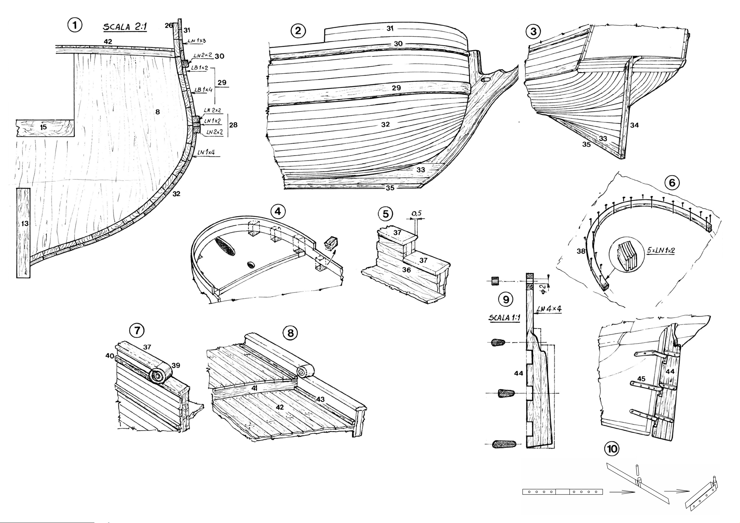
7) Secondo fasclame. Incollare Plnclntone 28 M quale, per facilítame la curvatura, é for mato da 3 listell!: un llstcllo céntrale da 1x2 afflancato da 2 llstelll da 2x2 nim, II posizio namento dell’inclntone é Indícalo nella tav, A, dove si nota che, ni centro
dello scafo, la linea Inferlore dell’inclntone é ya filo della linea di galleggIamento, mentro la curvatura verso Palto delle estremítá é piu accentuata rispetlo a queda delprimo fasclame so t tos tan te. Incollare la fascía gfalla 29 (3 llstelll da lx4píüun llstello
da 1x2 mm), pol I*Inclntone 30 interrotto In modo da lasciare due Incastrl nel quall verranno In segulto Incollatl I pa-rasartíe; completare II rivestlmento superlore col llstelll 31.Montare i listelli 32 della parte Inferlore del fasclame tenendo presente
quanto si é detto a proposito della rastrema zione verso prua del listelli, ¡noltre, nel settore di poppa, I llstelll rlvestono interamen-te la chiglia. Rivestlre la parte interiore della chiglla e lo sperone coi listelli 33, incollare il listello 34 sul bordo verticale di
poppa della chiglia ed infine incollare la con tro-chiglia 35. Praticare sudo sperone un foro ovale per il passaggio della legntura che forma il bompresso (figg. 1-2-3). Rlfinire accuratamente tutta la superficie con carta vetra-ta a grana sempre plu fine.
8) Raccordare la parte superiore del fasciame soguendo la linea Idéale che collega le estremítá delle ordinate e facendo rlferimento al profilo disegnato sulla lavóla " (alten zione ai gradinil). Asportare le estremilá sporgenti sopra la coperta (fig. 14),
Hsciare accuratamente e riveslire tutto l'Interno della múrala coi listelli 36, incollare II capodi-banda 37, che va dal gradino della coperta di prua alPestrema poppa, lase lando che spor ga circa 0, 5 mm, oltre il fasciame (fig, 5). II capodibanda 38 della
murata di prua, data la forte curvatura, va prepáralo a parte: capovolgere lo scafo e appoggiarc il settore di prua su una tavoletta di legno, tracciare il contorno del fasciame o stendere un sottile foglio di prastica trasparente sulla tavoletta* Bagnare,
curvare, incollare tra loro 5 llstelll da 1x2 mm e iasetari i essiccare fissati sulla tavoletta (fig, 6), Quancio la colla é asclutta, staccare ¡I capodibanda, aggiustarlo e Incollarlo sulla murata. Preparare i rae cordi 39, rlcavati dal tondino da 6 mm e Incollarll nei
punti dove il capodibanda si interrompe a forma un gradino, Incollare II llstello 40 sul flanco dello scafo come se fosse II proseguimento verso poppa del capodibanda posto lungo II mezzoponte (fig. 7)* Riveslire coi listelli 4? posti trasversalmente i
gradlni formati dalle interruzionl della coperta, Tracciare una linea lungo tutta la mezzeria della coperta quindi, pariendo dalla troccia-tuha e procedendo verso la murata, incollare il tavolato 42 fino a rivestire completamente la coperta. II tavolato é
formato da spezzoni di listello tunghi circa 80 mm incollati sfalsati e con le coste annerite con una matita, al fine di metiere in risalto la linea di unione tra le lavóle, Incollare il Ir incarino 43 lungo la linea di unione coper ta/murata (fig. 8).
9) Preparare II timone 44 ¡ncollando tra loro 4 spezzoni di llstello 4x4, sagomare II contorno ed agglustare II profilo in sezione. Praticare degll ¡ntagli In corrispondenza degli alloggiamenti per le cerniere e asportare le partí occedenti del listello, forare
da 2 mm l'estremitá superiore dell'asta (fig. 9). Incollare nel foro di 3 semicerniere 45 I perni 46, poi incollarle nei vanl sul timone, assicurandosi che appoggino bene sul fondo e ta-gliare la parte eccedente. Assottigliare leggermente e arrotondare gli
spígoli posterior! della chiglia; ¡nfilare sui perni le rimanenti 3 semicerniere, appoggiarc le stesse contro la chiglia, spingere il timone finché le flange delle cerniere si adattino perfettamente alia curvatura dello scafo e incollare. II timone dovrá trovarsl il
piü possibile viclno alia chiglia (fig. 10).
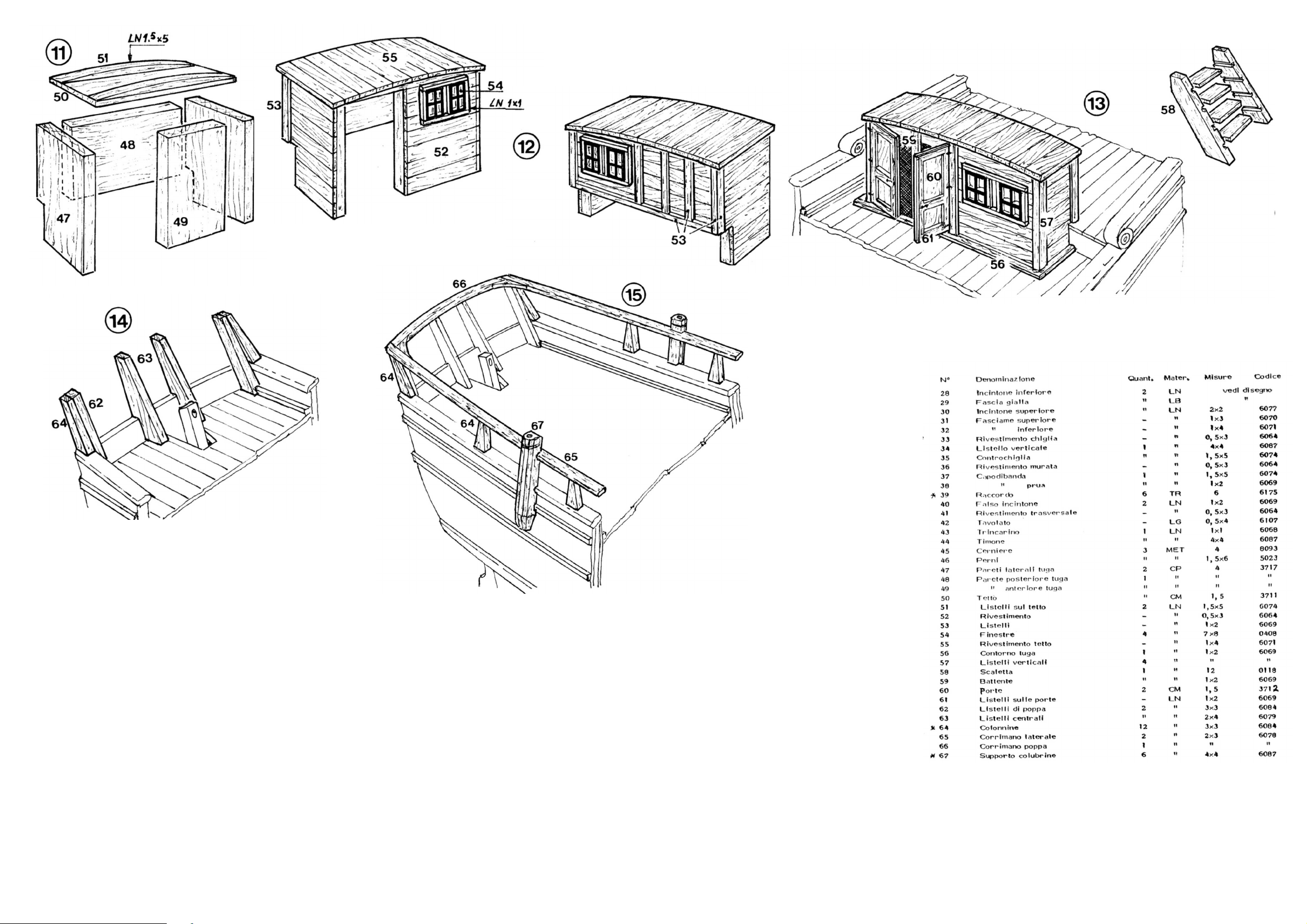
10)La tuga viene preparata a porte, poi incollata sullo scafo e completata delle rifinitu-re. Incollare, controllando che le 4 superfici lateral! si ano in squadra tro loro, i fianchi 47, la párete posteriore 48, la semiparete anterlore 49, il tetto 50 e su questo i
listelli 51 aggiustati ad arco di cerchio con le estremitá terminanti a zero (fig. II). Rivestire le 4 pareti coi listelli 52, incollare i listelli 53 e le finestre 54, contórnate dal listello Ixl, sulle pareti posteriore e anterlore, ricoprire il tetto coi listelli 55 lasclando
che spor-gano circo I mm oltre le paretidella tuga (fig. 12). Incastrare e incollare latuga nel va noaperto sulla coperta del mezzoponte (la párete posterioreappoggia sulla coperta del cassero). Le pareti devono essere vertlcali, mentre11 tetto si presenta
leggermente spiovente verso poppa, Incollare II llstello 56 sulla coperta, tutto intorno alia tuga, sulle cul pareti Interali vanno Incollatl i listelli verticall 57. Montare la scaletta 58, taglior la nella giusta lunghezza e Incollarlo nel vano della tuga, in corr
ispondenza della porta céntrale, appoggiata al mezzoponte e sul falso ponte 15, Incollare II listello 59 al centro del vano aperto sulla parte anteriore della tuga; incollare sulle porte 60 I llstelll 61, In-fine incollare le porte in poslzione seiniaperta (fig. 13),
11) Incollare I 2 listelli 62 appoggiati all1 interno dell’angolo formato dalla murata con lo specchlo di poppa, rispettnndo PalteiTa rllevata dalla taIncollare gil altrl 2 Ifstet-li 63 Incasti’atl sullo specchlo di poppa e appoggiati sulla coperta (fig. 14), Preparare
le colonnlne (6 per parte) che sostengono il corrlmano 65. Come si vede dalla tavola A Id colonnine sono leggermente rastremate verso Palto e di diverse altezze. La prima colon nina deve essere alto 12 mm, Pultlma é incollata al llstello 62 ed é della
stessa altezzat.
Le altre 4 colonnine central! vanno taglinte leggermente plu lunghe della mlsura rilevata dal dtsegno, quindi Incollate fortemente sul capodibanda, Agglustare Paltezza delle colon nine central! in modo che incollandovi sopra il corrimano, esso presentí
una leggera curvatura dalPandamento regulare. Incollare II corrlmano 66 di poppa II quale va precedentemente bagnato e curvato per facilítame il montaggio. Incollare un plccolo rlnforzo rica voto dal listello 2x3 dove I corrimano lateral! e di poppa si
congiungono (fig. 14). Prepa raro i supporti 67 per le colubrlnc come indícalo sul disegno, sul quall va pratlcato peró solo IMncastro superiore riel quale verrá pol Incollato II corrimano, Appogglare II suppor to contro lo scafo nella poslzione dove dávrá
venire Incollato, segnare o praticare gil In castri in corr Ispondenza del capodibanda 37 e delP incintone 40, incollare it supfx>rto in posizione verticale e contro II fasciame (fig. 15).
Designer: Luigi Volonte
Page 6

MV37 Halifax - plan 2
Table No. 2
7) Second planking. Glue the sheer-strake 28 consisting in 3 strips, to make the bending easier: a central strip tx2 and 2 strips 2x2 mm placed at its sides. The position of the sheer-strakc is indicated in the table A, where it can be seen that, in the middle of the hull, the lower line of the sheer—strake is at the edge of
the water line, while the ben-ding highwards of the ends is stronger compared with that of the first planking below.
Glue the yellow bond 29 (3 strips 1x4 and a strip 1x2), the sheer-strake 30, broken off so as to leave two grooves in which the channels shall be glued later on, complete the upper sheathing with the strips 31, Mount the strips 32 of the lower part of the planking taking care of what has been written concerning the
tapering of the strips towards the prow, besides, in the prow sector, the strips sheathe completely the keel. Sheathe the lower part of the keel and the ram with the strips 33, glue the strip 34 on the vertical stern edge of the keel and at last glue the false keel 35. Bore in the ram an oval hole for the passage of the rope
fastening the bowsprit (fig. 1-2-3). Sand carefully the whole surface with fine-grained sandpaper,
8) Adjust the upper part of the planking following the ideal line linking the ends of the frames and referring to the profile drawn on the table A (take care of the steps!). Trim off the ends sticking out of the deck (fig. 14), smooth carefully and sheathe the inside of the bulwark with the strips 36, glue the planksheer 37
going from the step of the fore deck to the stern, letting it stick about 0, 5 mm out of the planking (fig. 5). The planksheer 38 of the fore bulwark, in consideration of the strong bending must be prepared separately: turn the hull upside down and lean the fore sector on a wooden board, draw the outline of the planking
and lay a thin transparent plastic sheet on the board. Soak, bend and glue to each other 5 strips 1x2 mm and leave them to dry fixed on the board (fig. 6), When the glue has set, remove the planksheer, adjust it and glue it on the bulwark. Prepare the connections 39, made from dowel 6 mm, and glue them In the
points whore the planksheer Is broken off and forms a step. Glue the strip 40 on the hull side as the natural continuation towards the stern of the planksheer placed along the half-deck (fig. 7). Sheathe with the strips 41 placed crosswise the steps formed by the interruptions of the deck. Draw a line along the whole
centre line of the deck, then, starting from the marking and going on towards the bulwark, glue the deck planking 42 so as to sheathe completely the deck. The planking consists in pieces of strip about 80 mm long glued joggled; the sides must be blackened with a pencil, so as to show up the connection line between
the boards. Glue the stringer 43 along the connection line between deck and bulwark (fig. 8).
9) Prepare the rudder 44 glueing to each other pieces of strip 4x4, shape the contour and adjust the section. Make some cuts In correspondence of the hinges and remove the protruding parts of the strip, bore (2 mm) the upper part of the stock (fig, 9), Glue the pivots 46 in the hole of 3 half-hinges 45, then glue them
on the rudder, making sure that they lean well on the bottom and cut the exceeding part. Slightly reduce and roundoff the back corners of the keel; slip in the pivots the remaining 3 half-hinges, lean them against the keel, push the rudder, make the flanges of the hinges fit perfectly to the bending of the hull and glue.
The rudder shall be as near *s possible to the keel (fig. 10).
10) The bridge house is prepared separately, then glued on the hull and completed with the details. Glue the sides 47, the back wall 48, the fore wall 49, the roof 50 and on it the strips 51 placed like an arc with their ends reduced to zero (fig.11), Take care that the 4 side surfaces are at right angles to each other.
Sheathe the 4 walls with the strips 52, glue the strips 53 and the windows 54 with the strip 1x1 around them on the back and fore walls, sheathe the roof with the strips 55 letting them stick 1 mm out of the walls of the bridge house (fig. 12). Fit and glue the bridge house in the open space on the half-deck (the back
wall Is leaning on the quarter-deck). The walls must be vertical, while the roof is slightly sloping towards the stern. Glue the strip 56 on the deck, all around the bridge house and glue the vertical strips 57 on its side walls. Assemble the ladder 58, cut it to length and glue it in the space of the bridge house, in
correspondence of the central door, leaning on the half-deck and on the false deck 15. Glue the strip 59 In the middle of the open space on the fore wall of the bridge house; glue the strips 6? on the doors 60, at last glue the doors half-open (fig. 13).
11) Glue the 2 strips 62 leaning Inside the corner formed by the wall with the transom, taking care of the height, indicated in the tabled A glue the other 2 strips 63 fitted in the transom and leaning on the deck (fig. 14). Prepare the railposts (6 on each side) supporting the handrail 65. Table A shows that the railposts
are slightly tapered towards the top and are of different heights. The first rail-post must be 12 mm high, the last is glued to the strip 62 and is of the same height. The other 4 central railposts must be cut slightly longer than the size indicated on the drawing, then they must be glued tightly on the planksheer, Adjust
the height of the central railposts: glueing the handrail on them, it must have a slight regular bending. Glue the stern handrail 66: it must previously be soaked and bent to make the assembly easier. Glue a small reinforcement made from strip 2x3 where the side and stern handrails meet (fig. 14). Prepare the stands
67 for the culverins as Indicated on the drawing: take care that on them only the upper groove must be made in winch the handrail shall then be glued. Lean the stand against the hull positioned where it shall be glued, mark anti make the grooves in correspondence of the planksheer 37 and of the p lank sheer 40, glue
the stand in vertical position and against the planking (fig, 15).
Table n. 2
7) Oeuxiome bordé. Coller la préceinte 28 gui, pour en faciliter le courbement, est formée de 3 lattes: une latte centrale 1x2 flanquée de 2 lattes 2x2 mm, La position de la préceinte est Indiquée dans la table A, où Mon note que, au centre de la coque, la ligne Inférieure rie la préceinte est au fil de la ligne de flottaison,
tandis que la courbure vers le haut des extrémités est plus accentuée par rapport à celle du premier bordé. Coller la bande jaune 29 (3 lattes 1x4 plus une latte 1x2 mm) ensuite la latte 30, interrompue de façon à laisser deux embolturos où les porte-haubans seront ensuite collés, compléter le doublage supérieur avec
les lattes 31. Monter les lattes 32 de la partie inférieure du bor dé tenant compte de ce qu'on a dit à propos de la contracture vers la proue des lattes, en outre, dans le secteur do poupe, les lattes doublent entièrement la quille. Doubler la par tic inférieure fie la quille et l'éperon avec les lattes 33, coller la latte 34 sur
le bord vertical fie poupe de la quille et enfin coller la contre-quille 35. Pratiquer sur l'éperon un trauval pour le passage du liage arrêtant le beaupré (fig. 1-2-3). Polir soigneusement toute la surface avec du papier de verre à gros grain toujours plus fin,
8) Raccorder la partie supérieure tfrj bordé suivant la ligne Idéale reliant les extrémités des couples et se référant au profil dessiné sur la table (faire attention aux marches!)» Enlever les extrémités saillantes au-dessus du pont (flg. 14), niveler avec soin et doubler l'intérieur des murailles avec les lattes 36, coller le platbord 37, qui va de la marche du pont de proue à l'extrémité de la poupe, laissant qu'il sorte environ 0, 5 mm au-delà du bordé (flg. 5). Le plat-bord 38 de la muraille de proue, en considération de la courbure accentuée, doit être préparé à part: retourner la coque et appuyer le secteur de poupe sur' une tablette en bois,
tracer le contour du bordé et étendre une feuille subtile de plastique trasparente sur la tablette. Tremper, courber et coller entre elles 5 lattes 1x2 mm et les faire sécher fixées sur une tablette (fig. 6). Quand la colle est sèche, détacher le plat-bord, l'ajuster et le coller sur la muraille. Préparer les raccords 39, tirés de
baguette do 6 mm et les coller dans les points ou le plat-bord s'arrête et forme unemarche. Coller la latte40 sur le flanc de la coque comme si elle était la continuation vers la poupe du plat-bord placé le long du demi-pont (fig. 7). Avecles lattes 41 placées transversalement doubler les marches formées des interruptions
du pont. Tracer une ligne le long de la ligne médiane du pont ensuite, partant du traçage et procédant vers la muraille, coller le bordé 42 jusqu'à doubler entièrement le pont. Le bordé est formé de pièces de latte longues de 80 mm, les bords noircis à l'aide d'un crayon, afin de mettre en évidence la ligne de jonction
entre les tables. Coller' la fourrure de gouttière 43 le long de la ligne de jonction pont/muraille (fig. 8).
9) Préparer le gouvernail 44 collant entre elles 4 pièces de latte 4x4, façonner le contour et ajuster le profil en section. Pratiquer des entailles en correspondance des logements pour les charnières et enlever les parties excédantes de la latte, percer (2 mm) l'extrémité supérieure du support du gouvernail (fig. 9). Coller
dans le trou de 3 demi-charnières 45 les pivots 46, ensuite les coller sur le gouvernail, s'assurant qu'elles soient bien appuyées sur le fond et couper la partie excédante. Réduire légèrement et arrondir les arêtes postérieures de la quille; enfiler sur les pivots les restantes 3 demi-charnières, les appuyer contre la quille,
pousser le gouvernail jusqu'à ce que les brides des char -nières s'adaptent parfaitement à la courbure de la coque et coller. Le gouvernail devra se trouver le plus près possible de la quille (fig. 10).
10) Le rouf est préparé à part, collé sur la coque et complété des finissages. Coller, con trôlant que les 4 surfaces latérales «»oient en équerre entre elles, les flancs 47, la paroi postérieure 48, la demi-paroi 49, le toit 50 et sur celui-ci les lattes 51 ajustées en arc de cercle avec les extrémités se terminant à zéro (fig. 11).
Doubler les 4 parois avec les lattes 52, coller les lattes 53 et les fenêtres 54, entourées de la latte 1x1, sur les parois postérieure et antérieure, doubler le toit avec les lattes 55 laissant qu'elles sortent environ 1 mm des parois du rouf (fig. 12). Encastrer et coller le rouf dans la niche sur le pont du demi-pont (la paroi
postérieure est appuyée sur le pont du gaillard d'arrière). Les parois doivent être verticales, tandis que le toit est légèrement en pente vers, la poupe. Coller la latte 56 sur le pont, tout autour du rouf et coller sur les parois latérales les lattes verticales 57, Monter l'échelle 58, la couper dans la longueur exacte et la coller
dans la niche du rouf, en correspondance de la porte centrale, appuyée au demi-pont et sur le faux pont 15. Coller la latte 59 au centre de la niche ouverte sur la paroi antérieure du rouf; coller sur les portes 60 les lattes 6!, enfin coller les portes en position entrouverte (flg, 13).
11) Coller les 2 lattes 62 appuyées à l'intérieur du coin formé de la muraille avec ie miroir de proue respectant la hauteur indiquée sur la tabley ; coller les 2 lattes 63 et;» castrées sur le miroir de poupe et appuyées sur le pont (fig. 14). Préparer les colck^sT nette«-. (6 sur chaque côté) soutenant la main courante 65.
Comme l'on voit sur la tab.^ les colonnettes présentent une légère contracture vers le haut et sont de différentes h*», fcu.'s. La première colonnette doit être haute de 12 mm, la dernière est collée à la inlit 62 et est de la même hauteur. Les autres 4 colonnettes centrales sont coupées légèrement plus longues que la
mesure Indiquée sur le dessin* donc collées très bien sur le plat-bord. Ajuster In hauteur des colonnettes centrales de façon que la main courants, une fols collée, présente une légère et régulière courbure. Coller la main courarte de poupe 66 après l'avoir trempée et courbée pour en faciliter le montage*, Coller un
petit renfort tiré de latte 2x3 où les main courantes latérale et de poupe s'unrssent (flg. 14).Préparer les supports 67 pour les couleuvrlnes comme Indiqué sur le dessin, pratiquant seulement l'entaille supérieure où sera collée la main courante. Appuyer le support contre la coque dans la position où il sera collé, marquer
et pratiquer les entailles en correspondance du plat-bord 37 et de la préceinte 40, coller le stpport en position verticale et contre le bordé (fig, 15).
Tafel Nr. 2
7) Zweite Beplankung Das Bergholz 28 einkleben, das, für die Erleichterung der Beugung, aus 3 Leisten bestellt: einer Mittelleiste 1x2 und zwei 2x2 mm. Die Stellung des Bergholzes 28 ist auf der Tafel A, wo man merkt, dass die Unterlinie des Bergholzes am Mittelschiff, beider Wasserlinie ist; die Beugung 2u den höchsten
Teilen der Ende ist dagegen markanter im Verhältnis zu der der ersten unterliegenden Beplankung Das gelbe Band 29 (3 Leisten 1x4 und eine 1x2 mm) einkleben, dann das Bergholz 30, das unterbrochen ist, so «lass man zwei Zapfen für die Rüsten hat; die Oberbeplankung mit den Leisten 31 fertig machen. Die Leisten 32
des Unterteils der Beplankung einkleben, bedenkern, dass alles, was man schon über die Verjüngung der Leisten nach dem Vorschiff gesagt hat, noch gilt; am Heck bekleiden die Leisten den ganzen Kiel, Den Unterteil des Kiels und den Sporn mit den Leisten 33 bekleiden, die Leiste 34 an den Senkrechten 1I lecksrand des
Kiels einkleben, den Teil 35 einkleben. Auf den Sporn ein Loch für den Durchgang der' Verbindung des Bugspriets machen (Bilder 1-2-3), Mit immer feinerem Glaspapier die ganze Fläche gut polieren,
8) Den Oberteil der' Beplankung nach der Ideallinie verbinden (Verbindung der Enden der Spanten), auf das Profil der Tafel "B” Bezug nehmen (Achtung auf die Stufen!). Die auf den Deck hervorragenden Ende abnehmen (Bild 14), gut polieren, die ganze Innenseite der Bordwand mit den Leisten 36 bekleiden, das Stück
37 einkleben, das von der Stufe des Vorschiffsdecks bis zum Hock geht; es muss 7 mm länger als die Beplankung sein (Bild 5). Das Stück 38 der Vorschiffsbordwand muss man separat bereiten wegen der grossen Beugung: das Schiff Umstürzen, auf eine Holztafel den Vorschiffssektor legery, das Profil der Beplankung
zeichnen, auf die Tafel ein dünnes Blatt durchsichtlicher Plastik legen. Nassen, beugen, zwischen einander 5 Leisten 1x2 mm einkleben, sie auf der Tafel trocken werden lassen (Bild 6) Wenn der Leim trocken ist, das Stück 38 abnehmen, es nusgleichen und auf die Bordwand einkleben. Die Verbindungen 39 mit dem
Rundstab 6 mm, bereiten; sie im Punkt kleben, wo sich das Stück 38 unterbricht und eine Stufe bildet. Auf die Seite des Schiffsrumpfes, die Leiste 40 einkleben, als ob sie die Fortsetzung des Stücks 38 der Halbbrücke längs wäre (Bild 7). Mit den Leisten 41 die aus den Unterbrechungen des Decks bestandenen Stufen
durchquer bekleiden. Eine Linie längs der ganzen Mittellinie fies Decks zeichnen, aus dieser Linie beginnen zur Bordwand gehen, das Holzbelag 42 einkieben bis zur vollendeten Bekleidung des Decks, Das Holzbelag besteht aus Leistenstücken, zirka 80 mm lang, abgelenkt geklebt und mit den, durch einen schwarzen
Bleistift, schwarzgemalten Rändern, so dass man die Ver-bindungslinie zwischen den Tafeln hervorheben kann. Den Teil 43 die Verbindungslinie Deck/Bordwand entlang einkleben (Bild 8),
9)Das Ruder 44 bereiten, zwischeneinander 4 Leilstenstück ke 4x4 kleben, das Profil formen und ausgleichen. Einige Einschnitte bei den Räumen für die Scharniere machen; die überflüssigen Telle der Leiste wegnehmen, 2 mm das Oberende der Stange löchern (Bild 9). Ins Loch der 3 Halbscharnieren 45 die Zapfen 46
einkleben, die Scharnieren in die Räume auf dem Steuer einkleben, kontrolIieren, dass sic gut auf dein Grund stehen, den überflüssigen Teil schneiden. Leicht verdünnen, die Hinterkanten des Kiels abrunden; dle anderen 3 Halbscharnieren ln die Zapfen stecken, dieselben an de»» Kley lehnen, das Steuer drücken, bis die
Flansche der Scharnieren genau zur Beugung des Schiffsrumpfes aiipossen utid kleben. Das Steuer muss dem Kiel möglichst nah sein (Bild 10),
10) Den Brückenaufbau wird separat bereitet, dann muss man ihn auf das Schiffsrumpf einkieben und mit allen Garnituren vollenden. Kontrollieren, dass die 4 Seitenflächen senkrecht zwischeneinander sind, die Selten 47 kleben, so wie die Hinterwand 48, die vor Hegende Halbwand 49, das Dach 50 und darauf die Leisten
51, mit den In Null endenden Teilen kreisbogenförmig ausglelchen (Bild II). Mit den Leisten 52 die 4 Wände bekleiden, die Leisten 53 und die Fenster 54 kleben (auf die Hinten- und Vor der wände), das Dach mit den Leisten 55, I mm zirka als die Wände des Br'ückenaufbaus länger. Den Brückenaufbau In den geöffneten
Raum auf dem Deck der Halbbrücke einstecken und klebet! (die Hinterwand Ist auf den» Deck der Schiffsschanze). Die Wände müssen senkrecht sein, dagegen Ist das Dach zum Heck leicht abfallend. Auf das Dock die Leiste 56 um den Brückenaufbau einkleben, auf dessen Seitenwande die senkrechten Leisten 57 geklebt
werden. Die Treppe 58 legen, sie genau schneiden, sie in den Raum des Brücken-aufbaus bei der Mitteltür einkieben, auf der falschen Brücke 15 und an der Halbbrücke angelehnt. Die Leiste 59 inmitten des offenen Raums auf den Oberteil des Brückenauf-baus kleben; auf die Türen die Leisten 61 kleben und dann die
Türen halboffen einkleben (Bild 1 3).
11) Die 2 Leisten 62 in die Mitte der aus der Bordwand mit dem Hecksspiegel bestandenen Kante kleben, wie auf der Tafel A die Höhe gut achten; auf den Hecksspiegel die anderen 2 Leisten 63 legen, sie auf das Deck anlehnen und sie kleben (Bild 14). Die Säuler (6 für jeden Teil) bereiten, die den Handlauf 65 stützen. Wie
auf der Tafel, muss man die Säulen leicht nach oben und aus verschiedenen Höhen verjüngen. Die erste Säule muss 12 mm hoch sein, die letzte muss man an die Leiste 62 kleben und sie muss so hoch wie die Leiste sein. Die anderen 4 Mittelsäulen müssen leicht länger als die auf dem Bild sein und stark geklebt werden.
Die Höhe de»' Mittelsäulen ausglelchen, so dass der darauf geklebte Handlauf eine leichte, regelmässige Beugung zeigen kann. Den Heckshand lauf 66 einkleben, der vorher gefeucht und gebeugt wird um den Bau zu verleichtern. Eine kleine Stütze kleben, die aus der Leiste 2x3 besteht, wo sich die Seiten- und Hecks
Handläufe verbinden (Bild 14). Die Stütze 67 für die Feldschlangen wie auf dem Bild bereiten, auf die man nur den Obereinschnitt machen muss, In den denselben Handlauf geklebt wird. Die Stütze ans Schiff, in der Stellung des Klebens lehnen, ein kleines Zeichen machen, die Einschnitte bei dem Teil 37 und dem Berholz
40 zeichnen, die Stütze senkrecht und «in die Beplankung kleben (Bild 15).
Designer: Luigi Volonte
Page 7
Designer: Luigi Volonte
MV37 Halifax - plan 3
Tavola n. 3
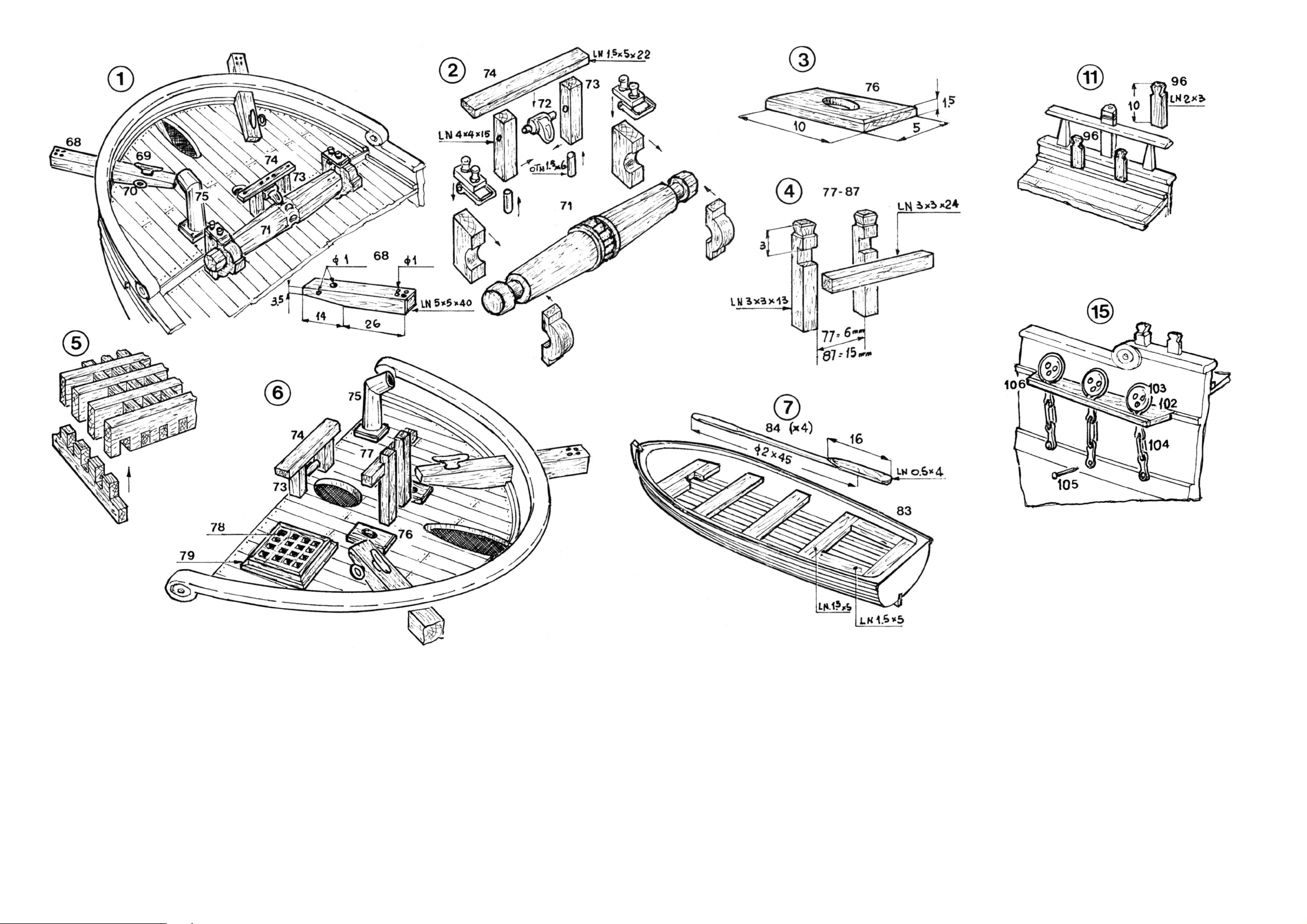
12) Praticare sulla murata di prua un foro quadrato da 5x5 mm col tato inferiore a filo del plano dolla coperta, nella esatta posizione indicata nella tavola^ ; preparare la gru di capone 68, Infilarla nel foro e Incollarla sulla coperta, Incollare nel fori sulla gru le gallocce 69 e l'anello 70, Montare sulla coperta, contro il gradino della coperta di prua,
Mangano 71 completo delle spallette; sempre del gruppo argano, Infilare I perni del cricchetto 72 nel fori sulle colonnine 73 e Incollare sulla coperta di prua In modo che l'estremità del cricchetto vada ad Impegnarsi nelle tacche al centro dell'argano, Incollare sopra le colonnine la tavola 74 con funzioni di cavigliera. Al fine di avere un fissaggio
sicuro, si consiglia di forare da ì, 5 mm la base delle colonnine e la coperta, infilare nel fori un pezzetto di tondino di ottone da 1, 5x6 mm e incollare , Il procedimento descritto vale anche per I blttonf posti davanti agli alberi. Incollare il camino 75 (fig, 1-2), Incollare i rinforzi 76 (fig, 3)o forare da 2, 5 mm tenendo il trapano inclinato verso poppa;
preparare II bilione 77 (fig, 4) e incollarlo davanti all'albero di trinchetto. Montare 2 palolati (una volta montati formano 2 quadrati da 40x40 mm), procedendo come segue: Incastrare tra loro, senza incollare, I listelli fresati poi, completato il grigliato, Immergerlo in acqua nella quale sia stata sciolta qualche goccia di colla vinilica, lascia re
asciugare per lettamente e spianare facendo scorrere il paiolato su un foglio di carta vetrata a grana fine (fig, 5); da uno degli elementi così ottenuti, ritagliare il palolato 70 (con 4 fori per lato), incollarlo sulla coperta unitamente al contorno 79 ricavato dal llstej lo 3x3 profilato a "l_" (fig, 6). Ritagliare II paiolato 80 (1 Ixl 1 fori) e Incollarlo sulla
coperta contornato dal listello 61, Montare I supporti 82 dopo averne adattato II profilo alla carena della scialuppa,
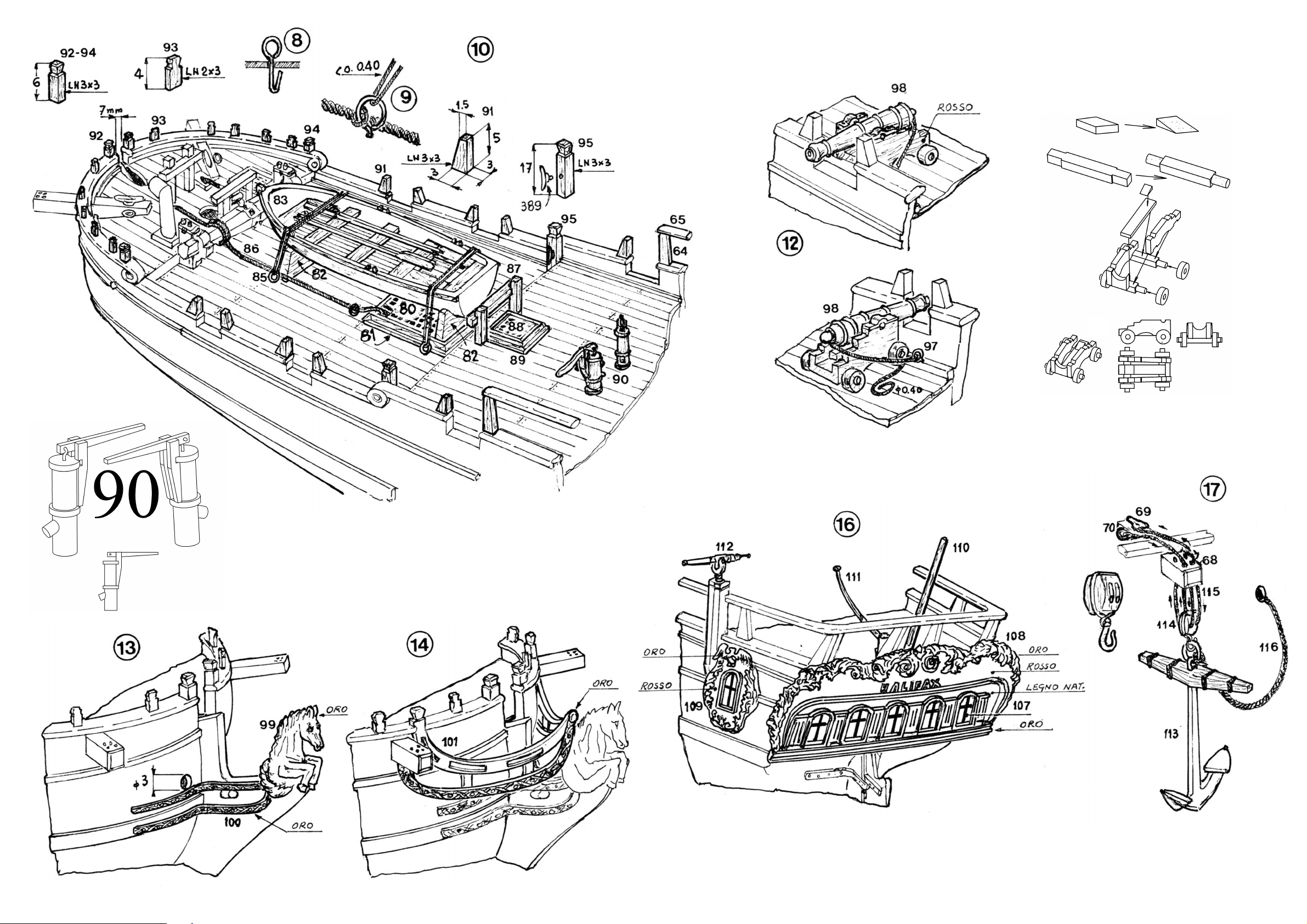
13) Montare la scialuppa 83 e I remi 84 secondo le Indicazioni della fig. 7j tingere Mlnter-no, il bordino laterale e i remi con mordente noce, verniciare di bianco opaco tutta la su perfide esterna, Legare i remi, due a due, al sedili. Praticare 6 fori da 1 mm sulla coperta e Incollare nel fori gli anellini 85 dopo averne piegato II gambo come si vede
nella ffg. 8 per evitare che si sfilino. Montare la gomena 86 dell'ancora: incollare ur> capo nel foro sul rinforzi 76, girarla 2 volte sull'argano, legarla a 2 degli anelli 85 (fig* 9) e incollare l'altro capo della gomena nel piccolo vano praticato sul paiolato. Legare in posizione la scialuppa con corda da 0, 4 mai, passata negli anelli 85, Preparare e
Incollare sul mezzoponte II bittone 87, il pololato 88 e il contorno 89 del tutto uguali al blttone 77 e al paiolato 78 (fig. 4 e 5). Incollare le 2 pompo 90 (fig. 10),
14) Tracciare sulla murala i 6 vani per il posizionamento dei cannoni; eseguire le aperture praticando con un seghetto i 2 tagli verticali che delimitano l'ampiezza poi, con un coltello ben affilato, asportare poco per volta la parte compresa tra I tagli. Evitare Muso di lime per questo genere di lavorazioni, incollare sullo murata, a lato del vani, le
spallette 91, Praticare sull'estrema prua della murata un vano largo 7 mm per il passaggio del bompresso. Incollare sulla murata o contro la stessa tutte le bitte e i bittoni cosi nu inorali a partire da prua: 2 bilioni 92 sulla murata a filo del vano passaggio bompresso, 10 bitte 93 sulla murata, 2 bittoni 94 sempre sulla murata di prua, 2 bittoni 95
appoggiati sulla coperta, contro la murata e II gradino tra la coperta ei II mezzoponte, infine le 4 bitte 96 appoggiate sul trincarino c contro la murata del cassero (flgg, 10-11), Praticare sulla coperta i fori da 1 min a lato delle aperture del cannoni e incollarvi gli anellini 97} montare i cannoni °8 e incollarli sulla coperta, legarli poi agli anellini con
corda da 0, 4 min (fig, 1 2).
15) Adattare lo sperone e incollare la polena 99 con colla epossidica; con molta attenzione, usando una pinza a becchi tondi, curvare, adattare e Incollare i 4 rinforzi 100 di metallo che collegano lo sperone allo scafo (fig. 13); incollare sullo scafo la coppia di serpe 101, si noti clic le estremità anteriori si congiungono e appoggiano sulla polena
(fig. 14), Incollare i parasartie 102 nei vani lasciati liberi dal l'incintone 30, montare le bigo_t te 103 nell'anello delle lande 104, Incastrare le lande negli alloggiamenti sui parasartie e fissarlo mediante i chiodini 105. Chiudere le lande nei loro alloggiamenti col listello 106 Incollato sul bordo del parasartie (fig. 15). Ritagliare i vetri 107 e incollarli
negl» appositi vani sullo specchio di poppa 108 e sulle finestre laterali 109. Incollare In posizione questi elementi, asportando parte degli incintone In corrispondenza delle finestre laterali, in modo die queste appoggino direttamente sul fasciame (fig. 1G). Incollare all'Inferno dello specchio di poppa il supporto 117 dell'asta portabandiera. A
questo pun to lo scafo è completo, fatta eccezione per l'asta portabandiera 110, In barra del timone 111, lo colubr ine 112 o le ancor e 113 coi relativi bozze II i 114, le manovre 1 I 5 e le gome ne 116 (figg. 16-17). Questi elementi vengono montati quando il modello à finito, poiché la loro presenza renderebbe difficoltoso II montaggio
dell'alberatura col relativo sartia me. Per quanto riguarda la colorazione, lo scafo non richiede alcuna verniciatura: à suf ficiente tingere di nero, con un semplice pennarello, gli Incintoti! 28, 30 e 40. A scopo protettivo, spruzzare interamente lo scafo con vernice nitro trasparente opaca utflizzan do una normale bomboletta spray.
Page 8
MV37 Halifax - plan 3
Designer: Luigi Volonte
Page 9
MV37 Halifax - plan 3
Table No. 3
12) Make on the Fore bulwark a square hole 5x5 with the lower side at the deck's edge, in the exact position indicated in the table A. prepare the cat davits 68, insert it in the hole and glue it on the deck, glue in the holes on the cat davit the cleats 69 and the ring 70. Mount the windlass 71 on the deck against the step of the fore deck; insert the
pins of the pawl 72 in the holes on the stanchions and glue on the fore deck so that the end of the pawl engages in the slots in the middle of the windlass, glue the board 74 acting as belaying pin-rack. It Is advisable to bore the base of the stanchions and the deck (1,5 mm), In order to have a strong fastening, insert in the holes a piece of brass
dowel 1,5x6 mm an<l glue. The described procedure is valid also for the bitts placed in front of the masts» Glue the funnel 75 (fig. 1-2), Glue the reinforcements 76 (fig. 3) and bore (2, 5 mm) holding the drill inclined towards the stern; prepare the bitt 77 (fig, 4) and glue it In front
of the fore mast. Prepare 2 gratings (after being assembled, they form 2 squares 40x40) mm proceeding as follows: fit the milled strips into each other, without glueing them, then when the grating is complete, dip it in water with some drops of vynil glue, allow it to dry perfectly and smooth making the grating slide on a sheet of fine-grained
sandpaper (fig. 5). From one of the elements obtained, cut out the grating 78 (with 4 holes on each side); glue it on the deck together with the contour 79, made from an L-shnped strip 3x3 (fig. 6). Cut out the grating 80 (11x11 holes) and glue it'on the deck surrounded by the strip 81. Mount the stands 82 after having adjusted their profile to
the keel of the lifeboat.
13) Mount the life-boat 83 and the oars 84 according to the indications of fig. 7; paint the inside, the side rim and the oars with mordant walnut colour, paint the whole outer surface matt white. Fasten the oar s to the seats, two by two. Make 6,1 mm holes on the deck and glue In the holes the rings 85 after having bent the shaft as indicated in
fig. 8 to prevent them from slipping out. Mount the rope 06 of the anchor: glue an end iti the hole on the reinforcements 76, turn it twice around the windlass, fasten it to 2 of the rings 85 (fig. 9) and glue the other end of the rope on the grating. Fasten the life-boat in position with rope 0, 4 mmt passed through the rings 85. Prepare and glue
on the halfdeck the bitt 87, the grating 88 and the contour 09, quite equal to the bitt 77 and the grating 78 (fig. 4 and 5). Glue the 2 pumps 90 (fig. 10).
14) Mark on the bulwark the 6 spaces for the guns: execute the openings making with a small saw the 2 vertical cuts delimiting the width, then with a sharp knife remove little by little the part between the cuts. Do not use any file for this type of working. Glue on the bulwark the parapets 91. Make on the prow of the bulwark a space 7 mm wide
for the pas-.age of the bowsprit. Glue on the bulwark or against it, all the bitts numbered as follows, starting from the prow: 2 bitts 92 on the bulwark at the edge of the space for the passage of the bowsprit, 10 bitts 93 on the bulwark, 2 bittes 94 always on the fore bulwark, 2 bitts 95 leaning on the deck, against the bulwark and step between
the deck and the half-deck, at last the 4 bitts 96 leaning on the stringer and against the bulwark of the quarter-deck (fig. 10-1 1). Make on the deck the I mm holes at the side of the openings for the guns and glue in them the rings 97; assemble the guns 98 and glue then» on the deck then tie them to the rings with 0, 4 mm rope (fig. 12).
15) Adjust the ram and glue the figure-head 99 with epoxy glue; with round nose pliers bend, adapt and glue very carefully the 4 metal reinforcements 100 linking the ram to the hull (fig. 13); glue on the hull the head-boards 101; lake care that the fore ends meet and lean on the figure-head (fig. 14). Glue the channels 102 in the spaces which
are not covered by the sheer-strake 30, mount the dead-eyes 103 in the ring of the chain-plates 104, fit the chain-plates on the channels and fix them in position with the small nails 105. Close the chain-plates with the strip 106 glued on the edge of the channel (fig. 15). Cut out the glasses 107 and glue them in the spaces on the transom 108
and on the side windows 109. Glue these elements in position, removing part of the sheer-strakes In correspondence of the side windows, so that they lean straight on the planking (fig. 16). Glue inside the transom the support 1 17 of the flag-staff. The hull Is now ready, with the exception of the flag-staff 110, the tiller-bar 111, the culverins 1
12 and the anchors 113 with the relative blocks 114, the rigging 115 and the ropes 116 (fig. 16-17). These elements must be mounted when the model is finished because their presence would make the mounting of the masting with the relative rigging difficult. As far as the colouring is concerned, the hull requires no painting: It is enough to
paint black, with a felt-pointed pen, the sheer-strakes 28, 30 and 40. Spray completely the hull with transparent, matt ni thro varnish, using a spray can.
Table n. 3
12) Pratiquer sur la muraille de proue un trou carré de 5x5 mm avec le côté Inférieur au fil du plan du pont, dans l'exacte position indiquée sur la tableA. préparer la gru de ca-pon 68, l'introduire dans le trou et la coller sur le pont, coller
dans les trous sur la grue les taquets 69 et l'anneau 70. Monter sur le pont contre la marche du pont de proue le cabestan 71; introduire les pivots de la partie 72 dans les trous sur les colonnettes 73 et coller sur le pont de proue de façon
que les extrémités de la pièce 72 s'adaptent dans les entailles au centre du cabestan; coller sur les colonnettes la table 74 faisant fonction, de râtelier da manoeuvre* Afin d'avoir une fixation s<!lre, on conseille de percer la base des
colonnettes et le pont (I, 5 mm), introduire dans les trous une pièce de baguette de laiton 1, 5x6 mm et coller. l_e procédé décrit vaut aussi pour les bittons placés devant les arbres. Coller la cheminée 75 (fig. 1-2), Coller les renforts 76
(fig, 3) et percer (2, 5 mm) tenant la perceuse inclinée vers la poupe; préparer le bitton 77 (fig. 4) et le coller «levant le mât de misaine. Monter 2 calllebotis {ils forment une fois montés 2 carrés 40x40 mm), procédant comme suit:
encastrer entre elles, sans collet', les lattes fraisés; lorsque le caillebotis est monté, le tremper dans l'eau avec quelques gouttes de colle vinylique. Laisser sécher parfalteieent et niveler faisant glisser le calllebotis sur une feuille de papier
de verre th grain fin (fig. 5); découper le caillebotis 78(avec 4 trous sur chaque côté), d'un des éléments ainsi obtenus, le coller sur le pont avec le contour 79 tiré de latte 3x3 en "L" (fig. 6). Découper le caillebotis 80 (llxll trous) et le coller
sur le pont entouré de la latte 81. Monter les supports 82 après en avoir adapté le profil à la carène «le la chaloupe.
13) Monter la chaloupe 83 et les rames 84 selon les indications de la figure 7; peindre l'intérieur, le bord latéral et les rames avec du mordant couleur noyer, peindre en blanc mat toute la surface extérieure. Lier les rames, deux à deux,
aux sièges. Pratiquer 6 trous de 1 mm sur le pont et coller dans les trous les anneaux 85 après en avoir plié la tige comme on voit dans la figure 8 pour éviter qu'ils sortent. Monter l'amarre 86 de l'ancre: en coller un bout dans le trou sur
les renforts 76, la faire tourner 2 fois sur le cabestan, la lier à 2 des anneaux 85 (fig. 9) et coller l'autre bout de l'amarre dans la petite niche sur le calllebotis. Lier on position la chaloupe avec de la corde 0, 4 mm, passée â travers les
anneaux 85. Préparer et coller sur le demi-pont le bitton 07, le calllebotis 88 et le contour 89 tout à fait égaux au bitton 77 et au calllebotis 78 (fig* 4 et 5). Coller les 2 pompes 20 (fig, 10),
14) Tracer surla muraille les6 niches pour le placement des canons, exécuter les ouver^ tures pratiquant avec une scie les 2 coupures verticales délimitant l'ampleur et, avecun couteau bien tranchant, enlever peu à peu lapartie comprise
entre les coupures Eviter l'emploi de limes pour ce genrede travaux. Coller sur la muraille, à côté des niches, les parapets 9 1. Pratiquer sur l'extrémité de la muraille vers la proue une niche de 7 mm de largeur pour le passage du beaupré.
Coller sur la muraille ou contre elle, tous les bittes et luttons ainsi numérotés a partir de la proue: 2 bittons 92 sur la muraille au fil de la niche pour le passage du beaupré, 10 bittes 93 sur la muraille, 2 bittons 94 toujours sur la muraille
de proue, 2 bittons 95 appuyés sur le pont, contre la muraille et la marche entre le pont et le demi-pont, enfin les 4 bittes 96 appuyées sur la fourrure de gouttière et contre la muraille «lu gaillard d'arrière (fig. 10-11). Pratiquer sur le
pont les trous «le 1 mm à côté des ouvertures des canons et coller les petits anneaux 97; monter les canons 98 et le coller sur le pont; les lier aux anneaux avec de la corde 0, 4 mm (fig. 12),
15) Adapter l’éperon et coller la figure de proue 99 avec de la colle apoxidlquej avec beaucoup d'attention, employant «Jos pinces rondos, courber, adapter et coller les 4 ren forts 100 de métal qui relient l'éperon à la coque (fig, 13);
œller sur la coque les herpes 101, «font les extrémités antérieures se relient et s'appuyent sur la figure de proue (fig* 14). Coller les porte-haubans 102 dans les niches laissées libres par la préceinte 30, monter les cnps-de-mouton 103
dans le trou des ferrures 104, encastrer les ferrures dans les logements sur les porte-haubans et les fixer avec les petits clous 105, Fermer les ferrures avec la latte 106 collée sur le bord des porte-haubans (fig, 15), Couper les vitres 107
et les coller dans les niches sur le rnlrolr de poupe 108 et sur les fenêtres latérales 109. Coller en position ces éléments, enlevant une partie des préceintes on correspondance des fenêtres latérales, de façon «jue celles-ci s’appuyent
directement sur le bordé (fig, 16). Coller à l'intérieur du miroir de poupe le support 117 de la hampe porte-drapeau. A ce point la coque est complète, «à l'exception de la hampe porte-drapeau 110, la barre du gouvernail 1 11, les
couleuvrlnes 1 I 2 et les ancres 113 avec leurs poulies 114, les manoeuvres 115 et les amarres 116 (fig. 16-17). Ces éléments sont montés fors> que le modèle est achevé, puisque leur présence rendrait difficile le montage de la mâture
avec les haubans. En ce qui concerne la peinture, la coque n'en requiert aucune: il suffit «le peindre en noir les préceintes 28, 30 et 40. Comme protéction, peindre entièrement la coque avec de la peinture transparente matte nltro,
employant un vaporisateur.
Tafel Nr. 3
12)Auf die Vor schiffsbordwand ein Vier eckiges Loch 5x5 mm machen, mit der Unterseite an der FIache des Decks, in der genauen Steilung wie auf der Tafel A. die Ankerkatt 68 bereiten, sie ins Loch stecken und auf das Deck kleben; in die
Löcher auf der Ankerkatt die Klampen 69 und den Ring 70 kleben. Auf das Deck an die Stufe des Vorschiffsdecks die Winde 71 stellen; was die Gruppe-Winden betrifft, die Zapfen der Sperrklinke 72 In die Löcher auf den Säulen 73 stecken
und auf das Vorschiffsdeck kleben, so dass das En de der Sperrklinke in die Einschnitte inmitten der Winde geht, die Tafel 74 als Belegnagel auf die Säulen kleben. Um ein festes Kleben zu haben, ist es besser das Deck und den Grund der
Säulen I, 5 mm zu löchern, in die Löcher ein Stück Rundmessing 1, 5x6 mm stecken und kleben. Die schon beschriebene Arbeit gilt auch für die Poller vor den Masten. Don Schlot 75 (Bild Lind 2) kleben. Die Stützen 76 kleben (Bild 3) und 2,
5 mm löchern (der' Bohrer muss zum Heck schief sein); den Poller 77 bereiten (Bll d 4), Ihn vor dem Fockmast kleben. Zwei Grätings (sie bilden 2 Vierecke 40x40 mm), wie folgt legen: ohne zu kleben, die gefrästen Leisten zwischeneinander
einschieben, dasGräting vollenden, sieins Wasser' mit einigen Tröpfen Vinylleim tauchen, alles guttrocken werdenlassen undmit einemfeinen Glaspapiereben machen(Bild 5); von einem sobekommenen Stück,das Gräting79 abschneiden
(mit 4 Löchern pro Seite), es auf das Deck zusam men mit dem aus der Leiste 3x3 bestandenen Umriss kleben (Bild 6). Das Gräting 80 ab-schnelden und es auf das Deck zusammen mit der Leiste 81 kleben. Die Stützen 82 mit dem, dem
Unterwasserschiff der Schaluppe angepassten Profil einsetzen.
13) Die Schaluppe 83 und die Ruder 84 legen, den Hinweisen des Bildes 7 nach; den Innen raum, die Ruder und den Seltenrand mit nussfarbigem Ätzmittel lackieren, die ganze Aus senflüche weiss lackieren. Zwei zu zwei die Ruder an die
Sitze legen. 6 Löcher 1 mm auf das Deck machen, in die Löcher die Ringe kleben, nachdem man den Stengel wie auf dem Bild 8 gebogen hat, um das Abstreifen zu hindern. Dos Ankertau 86 einsetzen; ein Stück ins Loch auf den Stützen 76
kleben, zweimal das Anker tau in der Winde drehen, es mit 2 der Ringe 85 verbinden, das andere Stück des Ankertaus ins kleine Loch auf dem Gräting kleben. Genau die Schaluppe binden, mit Seil0, 4 mm, durch die Ringe 85 gezogen. Den
Poller 87, das Gräting 88 und den Umriss 89 bereiten und auf die Halbbrücke kleben (diese Stücke sind dem Poller 77 und dem Gräting 78 ganz gleich (Bild 4-5). Die 2 Pumpen 90 einkleben (Bild 10),
14) Auf die Bordwand die 6 Räume für die Kanonen zeichnen; die Öffnungen verwirklichen, mit einer Metallsäge die 2 senkrechten Einschnitte machen, die die Breite bestimmen und dann, mit einem Messer, den zwischen den Einschnitten
eingeschlossenen Teil, langsam abnehmen. An die Bordwand, neben den Räumen, die Brustwehre 91 einkleben; für diese Art Arbeit den Feilengebrauch vermeiden. Auf das äußerliche Vorschiff der Bordwand einen Raum 7 mm breit für
den Gang des Bugspriets machen. Auf die Bordwand alle Poller nach der folgenden Reihe kleben; man beginnt vom Vorschiff: 2 Poller 92 auf die Bordwand am Raum-Gang Bugspriet, 10 Poller 93 auf die Bordwand, 2 Poller 94 immer auf
die Vorschiffsbordwand, 2 Poller 95 ans Deck, an der Bordwand und der Stufe zwischen Deck und Halbdeck, dann die 4 Poller 96 an den Stützbalken und an die Bordwand des Achterdecks (Bild 10-1 l). Auf das Deck die Löcher I mm bei den
Öffnungen der Kanonen machen und darin die Ringe 97 kleben; die Kanonen 98 aufstellen und sie auf das Deck kle ben, dann sie mit Seil 0, 4 mm zusammen mit den Ringen verbinden (Bild 12).
15) Den Sporn ausgleichen, die Galionsfigur 99 mit Epoxyleim kleben; mit viel Aufmerksamkeit und mit der Hilfe einer Zange die 4 MetalIstützen 100 beugen, ausgleichen, kleben, die den Sporn mit dem Schiffsrumpf verbinden (Bild 13);
auf den Schiffsrumpf die Galionsbretter 101 kleben, gut achten, dass sich die Vorderenden vereinigen und an die Galions figur anlehnen (Bild 14). Die Rüsten 102 in die vom Bergholz 30 frei gelassenen Räume kleben, die Jungfern 103
legen, die Püttingeisen in die Räume auf die Rüsten einzapfen, sie mit den Nägelchen 105 befestigen. Mit der Leiste 106 am Rand der Rüsten, die Pütting eisen in ihre Räume schliessen (Bild 15). Die Fensterscheiben 107 abschneiden und
sie in die bestimmten Räume auf dem Hecksspiegel 108 und auf den Seitenfenstern 109 kleben, genau diese Stücke kleben, langsam einige Teile der Berghölzer bei der Seitenfenstern abnehmen, so dass diese letzten gerade an die
Beplankung anlehnen (Bild 16). Innen des Hecksspiegel die Stütze 117 der Fahnenträgerstange kleben. Jetzt ist der Schiffsrumpf vollendet mit Ausnahme der Fahnenträgerstange 1 10, der Steuerstange 1 I 1, der Feldschlange 1 12, der
Anker 1 13 mit den bestimmten Blöcken 1 14, der Steuerungen I 15 und der Ankertaue 116 (Bild 16-17). Diese Stücke worden bei vollendeten Arbeit gestellt, denn ihre Anwesenheit wäre schlecht für den Einbau des Mastwerkes mit dem
dazugehörigen Tauwerk. Was die Färbung betrifft, braucht der Schiffsrumpf keine Lackierung; es reicht schwarz die Berghölzer 28, 30 und 40 zu lackieren. Als Schutz, den ganzen Schiffsrumpf mit durchsichtigem mattem Nitrolack spritzen
(normale Sprayflasche).
Designer: Luigi Volonte
Page 10

AVVERTENZE GENERALI PER UN CORRETTO MONTAGGIO DEL MODELLO
ATTREZZATURA CONSIGLIATA
¦ Carta abrasi va sottile e media
- Martelletto
- Colla vinilica e istantanea
- Forblcine piccole
- Scotch di carta
- Fissachiodi
- Molletta per panni
- Spilli
- Piegalistelli
- Pinzette
- Taglia balsa
- Trapanino con punte da 0,7-1
Molti modellisti incóminciano la costruzione di un modello senza prima leggere le istruzioni. col risultato che ad un certo punto vengono a
trovarsi in difficoltà. Il più delle volte queste difficoltà nascono proprio dal fatto di non aver preso visione dell'insieme délia costruzione e
di non aver seguito attentamente il ciclo di lavorazione. Se quasi sempre è possibile superare l incaglio. puô accadere che un montaggio
non effettuato al momento glusto. comprometta tutta la costruzione. PerciO invitiamo a leggere attentamente le avvertenze generali
rlportate qui di seguito che valgono per tutti i modelli. grandi o piccoli, di nostra produzione; consi- gliamo poi di seguire scrupolosamente
il ciclo di montaggio descritto nel disegno.
La costruzione del modello è progettata secondo una progressione lógica alio scopo di ren- derne il montaggio semplice con un minimo
di attrezzatura: lima, martello. coltello. carta vetrata e trapano. Per rendere più comprensibile la tettura delle istruzioni. abbiamo evitato di
proposito l uso di termini marinari e abbiamo disegnato quasi tutte le figure in prospettiva. ben sapendo che pochissimi modellisti hanno
dimestichezza col disegno meccanico.
Ognl disegno è formato da una o piùtavole grandi (A.B.C...) con le viste d insieme del modello finito e con le sezioni a grandezza naturale.
atte a fornire un orientamento generale nella costruzione. e da una serie di tavole più piccole. dedicate specificamente alla costruzione.
Ogni tavola rlporta un gruppo di operazioni da eseguire. le istruzioni per lesecuzione delle operazioni stesse e una distinta con le parti
necessarie.
La numerazione è progressiva secondo l ordine di montaggio e deve venire osservata scrupolosamente per evitare le difficoltà aile quali
si è accennato precedentemente. Raccomandiamo. prima di iniziare la costruzione. di.studiare attentamente il disegno. di individuare le
varie parti e di separare i listelli secondo le misure e il tipo di legno. La distinta annessa aile istruzioni è cosi composta: nella c olonna è
indicato il numero progressive del pezzo da montare, poi una sintética descrizione dello stesso. la quantité necessaria. il tipo di materiale.
le misure ed infine il códice meccanografico del singólo elemento. La colonna "materiale'. indicata da una sigla, va interpretata nel modo
seguente:
LP
= listelli paduca (rosso)
LB
= listelli bosso (giallo)
LF
= listelli faggio (marrone-rosa)
LT
=
listelli di tiglio (bianco)
FG
= faggio
LN-listelli di noce
NO
= noce
LM=listelli di mogano
OB
= obeche (bianco sporco)
LG
=
listelli tanganica (beige-grigio)
TR
= tondini ramino (bianco sporco)
LZ=listelli azzurri
MET
= metallo
LV=listelli verdi
OTN
= ottone
LE=listelli neri
PL
= plástica
LA
=
listelli acero (bianchi)
CO
= corda canapa
La scatola di montaggio contiene tutti i pezzi giá lavorati pronti per il montaggio. ad eccezione di alcunl particolari. molto semplici. che
devono venire ricavati da un listello o da un tondino. come indicato sul disegno. Per I esecuzione di questi particolari. é consigliabile l uso
del tagliabalsa o di piccoli scalpelli invece della lima, come sembrerebbe logico. Gli elementi da autocostruire sono indicad con un
asterisco accanto'al numero d ordine sulla distinta. Per gli ¡ncollaggi generici delle parti in legno consigliamo di usare colla bianca vinilica:,
per l unione di parti in legno con altre in metallo. colla epossidica rapida a 2 componenti. oppure colla cianoacrilica. Per quest'ultimo tipo
di colla, segure attentamente le istruzione allégate e sce- gliere il tipo adatto: metallo o rpetallo-legno ecc. In linea di massima. il legname
contenuto nella scatola di montaggio é di diverse qualitá e conferisce al modello finito i colori che piü si avvicinano alia realtá tuttavia.
quando necessita la verniciatura. i colori e tipi di vernlce da usare sono indicati su disegno.
Ancora una volta raccomandiamo di lavorare con calma, preeislone, senza fretta e di non passare ad una lavorazione successiva se non
si é ultimata quella in corso. SOPRATTUTTO LEGGERE SEMPRE ATTENTAMENTE LE ISTRUZIONI: SI EVITERANNO INUTILI
PERDITE DI TEMPO ED ERRORI IRREPARABILI
INSTRUCTIONS GENERALES POUR UN ASSEMBLAGE CORRECT DU MODELE
EQUIPEMENT RECOMMANDE
- Papier de verre (mince et moyen)
- Petit marteau
- Repoussoir
- Pince
- Colle blanche et instantanée
- Fichoir
- Coupoir
- Ciseaux
- Epingle
- Foreuse 0,7-1
- Scotch papier
- Outil pour border
Beaucoup de modélistes commencent la construction d'un modèle sans avoir lu les instructions, avec le résultat que, à un certain point,
ils se trouvent en difficulté.
Plusieurs fois ces difficultés naissent du fait qu'ils n'ont pas une vision générale de la construction et n on pas suivi exactement les phases
de montage. S'il est presque toujours possible de surmonter la difficulté, il peut arriver qu'un montage qui n'a pas étéeffectué au moment
exact compromette toute la construction. Pour cette raison nous vous invitons à lire avec attention les instructions générales indiquées
ci-dessous qui sont valables pour tous les modèles, grands ou petits, de notre production; nous conseillons en outre de suivre scrupuleusement le cycle de montage décrit dans le dessin. La construction du modèle est étudiée selon une progression logique afin de rendre le
montage simple avec peu d'outils: lime, marteau, couteau, papier de verre et perceuse. Pour rendre plus compréhensible la lecture des
instructions, nous avons évité exprès l'emploi de termes marins et avons dessiné presque toutes les figures en perspective, parce que
nous savons que peu de modélistesconnaissent le dessinmécanique. Chaque dessinest forméd'une ouplusieurs tables grandes (A,B,C)
avec les vues d'ensemble du modèle fini et avec les sections grandeur nature, qui donnent une idée générale de la construction, et d'une
série de tables plus petites, dédiées en particulier à la construction. Chaque table contient un groupe d'opérations à exécuter, les
instructios pour l'exécution des opérations mêmes et une liste des parties nécessaires. La numération est progressive selon l'ordre de
montage et doit être observée scrupuleusement pour éviter les difficultés citées avant. On recomande, avant de commencer la
construction, d'étudier le dessin avec attention, d'individuer les différentes parties et de séparer les lattes selon les mesures et le type de
bojs. La liste annexée aux instructions est ainsi composée: dans la première colonne est indiqué le numéro progressif de la pièce à
monter, ensuite il y a une description synthétique de la même, la quantité nécessaire, le type de matériel, les mesures et enfin le code
suit :
LP
= lisses de paduca (rouge)
LB
= lisses de buis (jaune)
LF
= Lisses de hêtre (marron rose)
LT
= lisses de tilleul (blanc)
FG
= hêtre
LN
= lisses de noyer
NO
= noyer
LM
= lisses d'acajou
OB
= obeche
LG
= lisses de tanganyka
TR
= baguettes ramin
LZ
= lisses bleues
MET
= metal
LV
= lisses vértes
OTN
= laiton
LE
= lisses noires
PL
= plastique
LA
= lisses d'erable (blanc)
CO
= corde chanvre
a boîte de montage contient toutes les pièces déjà travaillées, prêtes pour le montage, à ¡ exception de quelques détails très simples qui
seront tirés d'une latte ou d'une baguette, comme indiqué sur le dessin. Pour I exécution de ces détails, on conseille d employer des.
coupe-balsa ou de petits ciseaux au lieu de la lime, comme il semblerait logique. Les éléments qui doivent être construits par le modéliste
sont indiqués par un astérisque à côté du numéro d ordre sur la liste. Pour les collages génériques des parties en bois, on conseille
l'emploi d une colle vinylique: pour l'union de parties de bois avec d'autres de métal on conseille de la colle blanche cyanoacrylique. Pour
ce dernier type de colle, il faut suivre avec attention les instructions annexées et choisir le type convenable: métal-métal au métal-bois
etc. En principe. le bois contenu dans la boîte de montage est de différentes qualités et donne au modèle fini les couleurs qui sont plus
semblables à la réalité.
Quand il est nécessaire de peindre le modèle, les couleurs et le type de peinture qu'il faut employer sont indiqués sur le dessin. On
recommande encore une fois de travailler avec calme, précision, sans hâte et de ne pas passer à une phase successive si le travail en
cours n'a pas été achevé. SURTOUT IL FAUT TOUJOURS LIRE AVEC ATTENTION LES INSTRUCTIONS: ON EVITERA D'INUTILES
PERTES DE TEMPS ET DES FAUTES IRREPARABLES.
GENERAL INSTRUCTIONS FOR A CORRECT ASSEMBLY OF THE MODEL
- Nail nailer
- Clothes-peg
- Pin
- Plank bender
RECOMMENDED TOOLS
- Emery paper (thin and medium)
-
Tweezers
- Knife for wood
- Little drill 0,7-1
- Hammer
- White glue and instant glue
- Modeling scissors
- Paper scotch
- Nail nailer
- Clothes-peg
- Pin
- Plank bender
A lot of modellers begin the construction of a model without reading the instructions, with the result that at a certain point they find
themselves in difficulty: These difficulties are generally due to the fact that the modeller has not looked into the whole construction and
has not followed carefully the various stages of assembly. If it is nearly always possible to overcome the difficulty, it may happen that an
assembly operation, which has not been done at the right moment, compromises the whole construction. Therefore we recommend to
read attentively the following general instructions, valid for all the models, for the big ones as well as for the little ones, 'of our production;
we also recommend to follow scrupulouslythe different assembly stages described in the drawing. The construction of the model is studied
so as to make the assembly possible with very few tools: file, hammer, knife, sand-paper and drill. To make the reading of instructions
more comprehensible, marine terms have been avoided and we have drawn nearly all the figures in perspective, as we know that very
few modellers are familiar with the mechanical drawing. Each plan consists of one or more big tables (A,B,C.) with complete views of the
finished model and full-size sections giving a general idea of the construction. Each table contains a group of operations to be carried out
with the relative instructions and a list of the necessary parts. The numeration is progressive according to the assembly order and must
be observed scrupulously. To avoid the difficulties mentioned above, we recommend, before beginning the assembly, to study carefully
the drawing, to single out the different parts and to separate the strips according to the sizes and the type of wood. The list after the
instructions is so formed: in the first column the progressive number of the part to be assembled is indicated, then a synthetic description
of the piece, the necessary quantity, the type of material, the sizes and then the code of the part. The letters in.the column "material" have
the following meaning:
LP
= paduca laths (red)
LB
= boxwood laths (yellow)
LF
= beechwood laths (brown/pink)
LT
=
lime laths (white)
FG
= beechwood
LN=walnut laths
NO
= walnut
LM=mahogany laths
OB
= obeche
LG=tanganyka laths
TR
= ramin rods
LZ=blue laths
MET
= metal
LV=green laths
OTN
= brass
LE=black laths
PL
= plastic
LA
=
maple laths (white)
CO
= hamp rope
The kit contains worked pieces ready for assembly, with the exception of some most easy details, which must be made out of a strip or a
rod as indicated in the drawing. For the execution of these details, it is advisable to use a balsacutter or small chisels instead of a file. The
parts to be constructed by the modeller are Indicated by an asterisk near the numerical order on the list. For thegeneric glueing of wooden
parts we advise the modeller to use white vinyl glue: for the union of wooden parts with others in metal, epoxy glue with two components
or cyanoacrylic glue. For this latter type, follow carefully the enclosed instructions and chose the suitable type: metal with metal ore metal
with wood etc. The wood contained in the kit is of different sorts and gives the finished model the most realistic colours; anyway, when
painting is requested, the colours and the type of painting to be'used are indicated on the drawing.
We recommend once more to work quietly, accurately and without hurry and not to go over to a subsequent work if the one in course has
not been completely finished. ABOVE ALL IT IS NECESSARY TO READ CAREFULLY THE INSTRUCTIONS: UNNECESSARY LOSSES
OF TIME AND IRRETRIEVABLE MISTAKES WILL THUS BE AVOIDED.
ALLGEMEINE ANWEISUNGEN FUER
EINEN KORREKTEN BAU
BERATENE WERKZEUGE
- Glaspapier (feine und mittlere Groesse)
- Haemmerchen
- Nagelheber
- Federzange
- Vynilleim und Instantleim
- Federbauklammer
- Balsamesser
- Kleine Schere
- Stecknadel
- Drillbohrer 0,7-1
- Papierscotch
- Leistenbieger
Viele Modellbauer beginnen den Bau, ohne die Anweisungen gut zu lesen. Das verursacht viele Schwierigkeiten, die das Endergebnis
beeintraechtigen koennen. Um das zu vermeiden, sollte man die Anweisungen aufmerksam lesen, weil sie den korrekten Einbauverfahren
erlaeutern. Die folgenden Anweisungen sind fuer alle Modelle gueltig und koennen Ihre Arbeit vereinfachen.
Man braucht auch kleine und einfache Einrichtung: Feile, Hammer, Messer, Glaspapier und Bohrer. Um die Anweisungen klar zu
erlaeutern, haben wir keine Seewoerter gebraucht und fast alle Bilder wurden in Perspektive gezeichnet.
Jede Zeichnung besteht aus einer oder mehr Tafeln (A, B, C usw.) mit Ansichten des schon montierten Schiffes und mit allen Sektibnen
in natuerlicher Groesse, um eine generelle Richtlinie zu geben, und aus kleineren Tafeln, die kleinen Beschreibungen von bestimmten
Arbeiten, Anweisungen fuer die Arbeitsausfuehrung und eine Liste aller Bestandteile enthalten. Diese Tafeln sind fortlaufend numeriert.
Bevor den Bau empfehlen wir, die verschiedenen Teile zu finden, und die Leisten nach den Massen und nach dem Holztyp zu verteilen.
Die Anweisungen enthalten auch eine Liste, die die fortlaufende Nummer, eine kleine Beschreibung, die nöetige Menge, den Stofftyp und
den Buchstabenwort jedes Stueckes angibt. Das Material wird wie folgt bezeichnet:
LB = leisten aus buchsbaum (gelb)
LF = leisten aus buche (braun-heilrot)
LT = lindenleisten (weiss) FG = buche
LN = nussbaumleisten NO = nussbaum
LM = mahagonileisten OB = abachi
LG = tangajicaleisten (beige-grau) TR = raminrundstäbe
LZ = bleue leisten MET = metall
LV = grüne leisten OTN = messing
LE = schwarze leisten PL = plastik
LA = leisten aus ahorn (Weiss) CO = hanfgarn
Der Baukast enthaelt fast alle schon bearbeitete und fuer den Bau'fertige Stuecke.
Einige Teile muessen aber von dem Modellbauer selbst mit der Hilfe eines kleinen Beitels (kein Feilen) gemacht werden. Anweisungen
dafuer kann man auf die entsprechende Tafel finden. Diese Stuecke werden durch ein besonderes Zeichen gezeigt. Fuer die Klebung
der Holzteile m uss man Weissvynilleim benutzen, fuer die Klebung von Holzteilen mit Metallteilen muss man dagegen Epoxy- oder
Zyanoakrilikleim benutzen. Fuer diesen letzen Leimtyp bitte aufmerksam die Anweisungen folgen. Der Baukast enthaelt verschiedene
Holzarten, die dem vollendeten Modell die genaue Farbe des Originellen geben. Wenn man aber das Modell beizen moechte, werden die
genauen Faerb.e und die richtigen Lacktypen auf dem Bild beschrieben.
Noch einmal moechten wir empfehlen, mit Ruhe and Aufmerksamkeit zu arbeiten und, der gezeigte Einbauverfahren ordentlich zu folgen.
BESONDERS MUSS MAN SEHR GUT UND AUFMERKSAM DIE ANWEISUNGEN LESEN, UM KEINE ZEIT ZU VERLIEREN UND
KEINE FEHLER ZU MACHEN.
 Loading...