

Page 1
8189 Century Boulevard • Minneapolis, MN 55317-8002 • USA
800-843-5116 • 952-556-4900 • Fax 952-556-4997
[email protected] • www.mamacsys.com
For Additional Information See PR-282 Data Sheet
SPECIFICATIONS
Accuracy*: ±1% FS
Overpressure: 300% of rated range
Burst Pressure: 500% of rated range
Maximum Static Pressure: 200% of DP range
Supply Voltage: 12-40 VDC
12-35 VAC (VDC output units only)
Supply Current: VDC Units - 10 mA max.
mA Units - 20 mA max.
Load Impedance: 3K ohms max. at 40 VDC (mA output units)
1K ohms min. (VDC output units)
Enclosure: 16 Ga Steel - NEMA 1
Finish: Baked on Enamel - PMS2GR88B
EMC Conformance:
61000-4-2, 3, 4, 5, 6 & 11
Compensated Temp Range: 0°F - 180°F (-18°C-82°C)
T.C. Error: ±0.025%/°F (.03%/°C)
Media Compatibility: Liquid/gases compatible to 316L SS
Port Connection: 1/8” NPT
Environmental: 10-90%RH Non-Condensing
Termination: Unpluggable screw terminal block
Wire Size: 12 Ga max.
Weight: 1.7 lbs. (.75 kg)
* Includes linearity, repeatability, hysteresis, stability and temp compensation
U.S. PATENT NO. 6484587
EN 55022, 55024, 61000-3-3,
RoHS
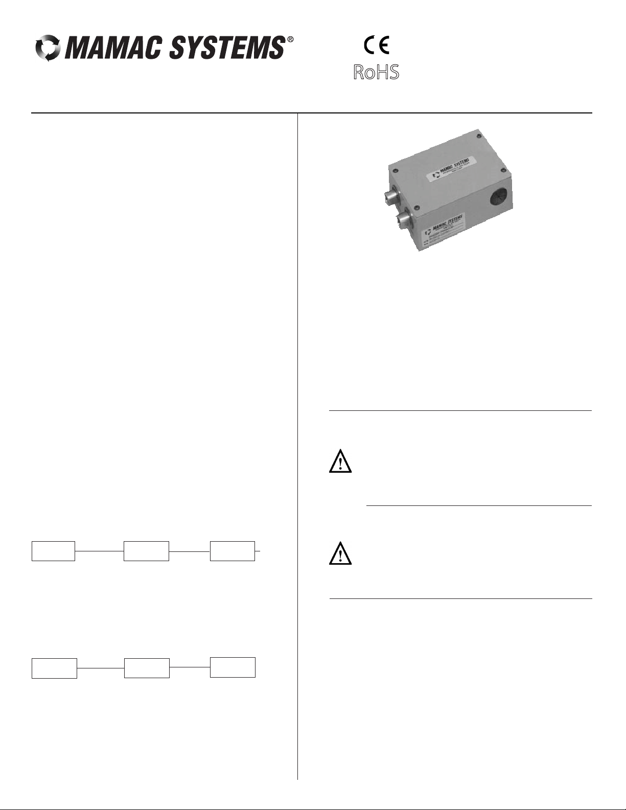
DIFFERENTIAL PRESSURE SENSOR
INSTALLATION
Inspection
Requirements
Inspect the package for damage. If damaged, notify the appropriate
carrier immediately. If undamaged, open the package and inspect
the device for obvious damage. Return damaged products.
• Tools (not provided)
• Appropriate accessories
• Four #8 self-tapping mounting screws (not provided)
• Training: Installer must be a qualified, experienced technician
Warning:
• Do not use on oxygen service, in an explosive/hazardous
environment, or with flammable/combustible media.
• Disconnect power supply before installation to prevent
electrical shock and equipment damage.
• Make all connections in accordance with the job wiring
diagram and in accordance with national and local
electrical codes. Use copper conductors only.
Model PR-282
Technical Information
TI.282-04
- Digital Volt-ohm Meter (DVM)
- Appropriate screwdriver for mounting screws
- Appropriate drill and drill bit for mounting screws
ORDERING INFORMATION: PR-282-
OUTPUT
1) 0-1 VDC
2) 0-5 VDC
3) 0-10 VDC
4) 4-20 mA
(2-wire)*
OUTPUT
TYPE
1) Direct
* Available with 24VDC supply voltage only
PRESSURE
RANGE
1) 0-20 psid
2) 0-30 psid
3) 0-50 psid
4) 0-100 psid
5) 0-200 psid
6) 0-300 psid
7) Custom
OUTPUT
AVERAGING
2) Without
SUPPLY
VOLTAGE
A) 24 VDC
B) 24 VAC
OUTPUT
CLIPPING
B) Without
Mounting
Wiring
Caution:
• Use electrostatic discharge precautions (e.g., use of wrist
straps) during installation and wiring to prevent equipment
damage.
• Avoid locations where severe shock or vibration, excessive
moisture or corrosive fumes are present.
• Do not exceed ratings of the device.
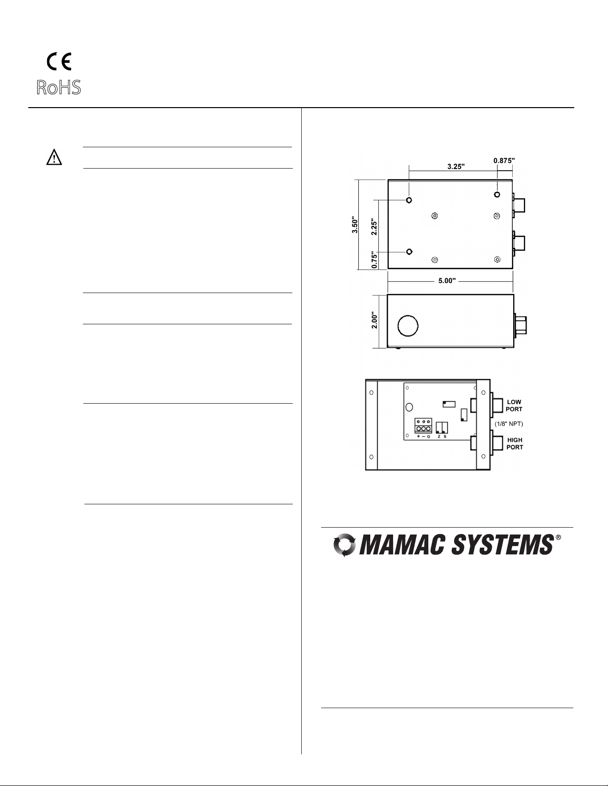
Refer to Figure 5 for mounting dimensions.
1. Remove the transducer cover using a Phillips head
screwdriver.
2. Select the mounting location.
3. Mount transducer on a vertical surface with four #8 self-tapping
screws (not provided).
4. Pull wires through bottom of enclosure and make necessary
connections.
5. Replace cover and make pneumatic connections.
Use maximum 12 AWG wire for wiring terminals. Refer to
Figures 1, 2, 3, & 4 for wiring information.
(Wiring Instructions continued on pages 2 and 3.)
Page 2
Page 2 of 4
Model PR-282
Technical Information
TI.282-04
RoHS
DIFFERENTIAL PRESSURE SENSOR
mA Output
+
—
Z S
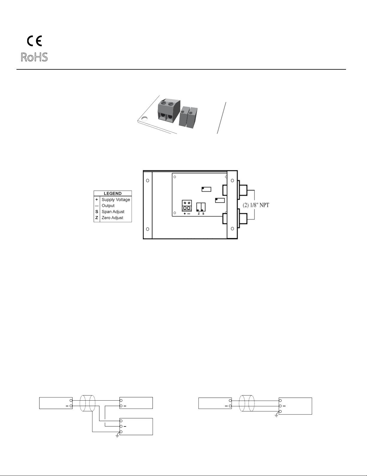
Wiring PR-282 Units with mA Output
PR-282 Differential Pressure Transducer with mA Output
The PR-282 pressure transducers with 4-20 mA output units are powered with a 12-40 VDC supply.
The following describes the proper wiring of these pressure transducers with mA output:
1. Remove the terminal block by carefully pulling it off the circuit board.
2. Locate the [+] and [-] terminal markings on the board.
3. Attach the supply voltage to the [+] lead.
4. Connect the 4-20 mA output ([-] terminal) to the controller’s input terminal.
5. Ensure that the power supply common is attached to the common bus of the controller.
6. Re-insert the terminal block to the circuit board and apply power to the unit.
7. Check for the appropriate output signal using a DVM set on DC milliamps connected in series with the [-] terminal.
TYPICAL APPLICATIONS (wiring diagrams)
Figure 1 and Figure 2 illustrate typical wiring diagrams for the PR-282, 4-20 mA, 2-wire, Differential Pressure Transducer.
Figure 1 - Wiring for mA Differential Pressure Transducers with External DC Power
Supply
mA Output Transducer Only 12-40 VDC Power Supply
+
+
Controller / Meter / Recorder
Input Signal
+
Common
Shield/Ground
Figure 2 - Wiring for mA Differential Pressure Transducers where the Controller or
Meter has an Internal DC Power Supply
mA Output Transducer Only
+
Controller / Meter / Recorder
Input Signal
+
Common
Shield/Ground
Page 3
Page 3 of 4
RoHS
DIFFERENTIAL PRESSURE SENSOR
VDC Output
+
—
O
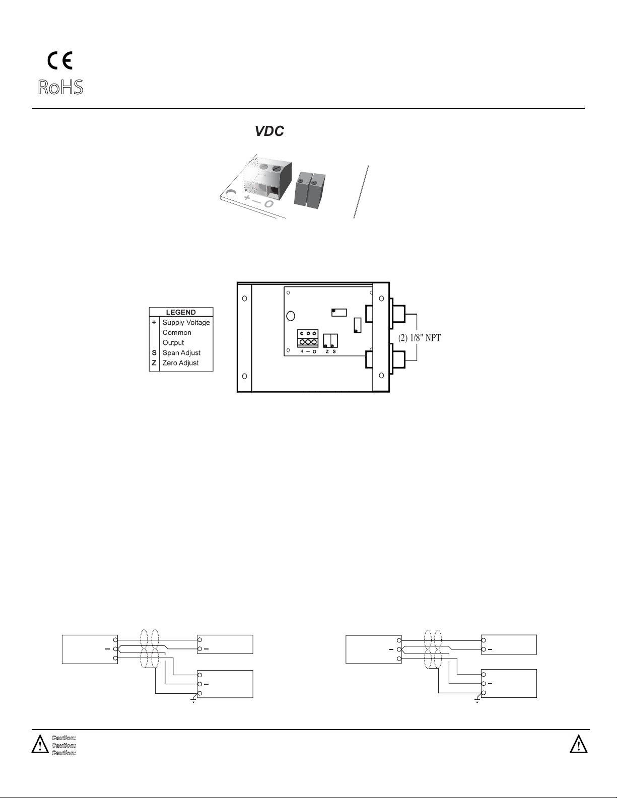
Wiring PR-282 Units with VDC Output
PR-282 Differential Pressure Transducer with VDC Output
Z S
Model PR-282
Technical Information
TI.282-04
—
O
The PR-282 pressure transducers with VDC output can be powered with either a 12-40 VDC or 12-35 VAC.
The following describes the proper wiring of these pressure transducers with VDC output:
1. Remove the terminal block by carefully pulling it off the circuit board.
2. Locate the [+], [-] and [O] terminal markings on the board.
3. Attach the power wires to the [+] and [-] terminals. The [-] terminal is also the negative terminal.
4. Connect the [O] terminal, which is the positive VDC output terminal, to the controller’s input terminal.
5. Re-insert the terminal block to the circuit board and apply power to the unit.
6. Check the appropriate VDC output using a voltmeter set on DC volts connected to the [O] and [-] terminals.
TYPICAL APPLICATIONS (wiring diagrams)
Figure 3 and Figure 4 illustrate typical wiring diagrams for the PR-282, 0-5/0-10 VDC Differential Pressure Transducer.
Figure 3 - Wiring for VDC Differential Pressure Transducers when applied with
External AC Supply
Figure 4 - Wiring for VDC Differential Pressure Transducers when applied with
External DC Supply
VDC Output Transducer Only 12-35 VAC Transformer
Caution: If you are using grounded AC, the hot wire must be on the [+] terminal. Also, if you are using a controller without built-in isolation, use an isolation transformer to supply the PR-282.
Caution: This product contains a half-wave rectifier power supply and must not be powered off transformers used to power other devices utilizing non-insolated full-wave rectifier power supplies.
Caution: When multiple PR-282 units are powered from the same transformer, damage will result unless all 24G power leads are connected to the same power lead on all devices. It is
mandatory that correct phasing be maintained when powering more than one device from a single transducer.
Supply
Common
Signal
Hot
+
0
+
Neutral
Controller / Meter / Recorder
Input Signal
+
Common
Shield/Ground
VDC Output Transducer Only 12-40 VDC Power Supply
Supply
Common
Signal
+
0
+
Controller / Meter / Recorder
Input Signal
+
Common
Shield/Ground
Page 4
Page 4 of 4
RoHS
Model PR-282
Technical Information
TI.282-04
DIFFERENTIAL PRESSURE SENSOR
CHECKOUT DIMENSIONAL DATA
Transducer
Operation
CALIBRATION
1. Verify that the unit is mounted in the correct position.
2. Verify appropriate input signal and supply voltage.
CAUTION: Never connect 120 VAC to these transducers.
Never connect AC voltage to a unit intended for DC supply.
3. Verify appropriate configuration range.
This is a rough functional check only.
1. Adjust the pressure to obtain maximum output signal for
appropriate range.
2. Output should be 20 mA or 5 or 10 VDC.
3. Adjust the pressure to obtain minimum output signal.
4. Output should be 4 mA or 0 VDC.
NOTE: The PR-282 is a highly accurate device. For
applications requiring a high degree of accuracy, the use of
laboratory quality meters and gauges are recommended.
All units are factory calibrated to meet or exceed published
specifications. If field adjustment is necessary, follow the
instructions below.
Calibration of PR-282 mA Units
1. Connect terminals [+] and [-] to the appropriate power source.
2. Connect the DVM in series on the [-] terminal.
3. Apply low pressure to the unit and carefully adjust the zero
trimmer (Z) to obtain desired low output.
4. Apply high pressure to the unit and adjust span trimmer [S] to
obtain the desired high output pressure.
5. Repeat steps 3 and 4 until desired calibration is achieved.
Figure 5 - PR-282 Differential Pressure Transducer dimensions shown in
inches.
MAINTENANCE
FIELD REPAIR
WARRANTY
Calibration of PR-282 VDC Units
1. Connect terminals [+] and [-] to the appropriate power source.
The [-] terminal is also the negative output terminal.
2. Connect the DVM on DC volts across [O] and [-] terminal.
3. Apply low pressure to the unit and carefully adjust the zero
trimmer (Z) to obtain desired low output.
4. Apply high pressure to the unit and adjust span trimmer [S] to
obtain the desired high output pressure.
5. Repeat steps 3 and 4 until desired calibration is achieved.
Regular maintenance of the total system is recommended to
assure sustained optimum performance.
None. Replace with a functional unit.
See Data Sheet for additional information.
For Technical / Application Assistance call your nearest office
8189 Century Boulevard • Minneapolis, MN 55317-8002 • USA
800-843-5116 • 952-556-4900 • Fax 952-556-4997
[email protected] • www.mamacsys.com
EUROPE
4200 Waterside Centre
Solihull Parkway
Birmingham • West Midlands
B37 7YN • United Kingdom
01384-271113 • Fax 01384-271114
905-474-9215 • Fax 905-474-0876
ASIA
1 Fullerton Road #02-01
One Fullerton
Singapore • 049213
65-31581826 • Fax 65-31581826
MAMAC Systems, Inc., reserves the right to change any specifications
without notice to improve performance, reliability, or function of our products.
08-8395-4333 • Fax 08-8395-4433
CANADA
675 Cochrane Drive
East Tower • 6th Floor
Toronto • Ontario
L3R 0B8 • Canada
AUSTRALIA
4 Armiger Court, Unit 2
Adelaide • S.A.
5088 • Australia
TI.282-04
 Loading...