

Page 1

RoHS
Model HU-226
Technical Information
TI.226-05
HUMIDITY / TEMP SENSOR
For Additional Information See HU-226 Data Sheet
HUMIDITY TRANSDUCER SPECIFICATIONS
Accuracy*: ± 2% / ±3% RH
Range: 0-100% RH
Hysteresis: ± 1%
Supply Voltage: 12-40 VDC
12-35 VAC (VDC output units only)
Compensated Temp Range: -30°F to 130°F (-35°C to 55°C)
Load Impedance: 1.5K ohms max. at 40 VDC (mA output units)
1K ohms min. (VDC output units)
* Includes non-linearilty and non-repeatability
THERMISTOR SENSOR SPECIFICATIONS
Interchangeability: ± 0.2°C
Heat Dissipation: 3.0 mW/°C
R/T Characteristics: Refer to TI.700-11 (See Temperature Sensor section)
Operating Temp Range: -30°F to 130°F (-35°C to 55°C)
ORDERING INFORMATION - HU-226-
ACCURACY
± 2%
± 3%
OUTPUT
mA
(4-20 mA 2-wire)
VDC
(0-5 VDC/0-10 VDC
field selectable)
HU-226
Duct Mount
1
2
3
4
5
7
8
10
12
13
14
15
TEMP SENSOR
100 ohm Platinum RTD
1,000 ohm Nickel RTD
(5,000 PPM)
1,000 ohm Platinum RTD
1,000 ohm Nickel RTD
(6,000 PPM)
1,000 ohm Balco RTD
10,000 ohm NTC Thermistor
(Type III)
10,000 ohm NTC Thermistor
(Carel)
3,000 ohm NTC Thermistor
10,000 ohm NTC Thermistor
(Type II)
5,000 ohm NTC Thermistor
1,035 ohm Silicon PTC
100,000 ohm NTC
Thermistor
PLATINUM RTD SENSOR SPECIFICATIONS
Accuracy: 0.12% at 0°C
Resistance: 100 or 1,000 ohm at 0°C
Standard: DIN 43760
Heat Dissipation: 3.0 mW/°C
R/T Characteristics: Refer to TI.700-11 (See Temperature Sensor section)
Operating Temp Range: -30°F to 130°F (-35°C to 55°C)
GENERAL SPECIFICATIONS
Environmental: 10-90%RH Non-Condensing
Enclosure: 18 Ga C.R. Steel NEMA 4 (IP-65)
Finish: Baked on enamel - PMS2GR88B
Termination: Unpluggable screw terminal block
Wire Size: 12 Ga maximum
Weight: Duct Mount: 1.0 lbs. (.45 kg)
CONFORMANCE & TESTING
RoHS Compliant
EMC Testing: BS EN 55022:1998, BS EN 55024:1998,
EN 61000-3-3, EN 61000-4-2,
EN 61000-4-3, EN 61000-4-4,
EN 61000-4-5, EN 61000-4-6
EN 61000-4-11
Ex: HU-226-2-mA-3 - Humidity/Temp
Sensor, ±2%RH accuracy with 4-20 mA
output and 1,000-ohm Platinum RTD.
For Resistance vs. Temperature Tables,
please refer to TI.700.11
INSTALLATION
Inspection
Requirements
Warning:
Caution:
Inspect the package for damage. If damaged, notify the appropriate
carrier immediately. If undamaged, open the package and inspect
the device for obvious damage. Return damaged products.
• Tools (not provided)
- Digital Volt-ohm Meter (DVM)
- Appropriate screwdriver for mounting screws
- Appropriate drill and drill bit for mounting screws
• Appropriate accessories
• Two #8 self-tapping mounting screws (not provided)
• Training: Installer must be a qualified, experienced technician
• Do not use on oxygen service, in an explosive/hazardous
environment, or with flammable/combustible media.
• Disconnect power supply before installation to prevent
electrical shock and equipment damage.
• Make all connections in accordance with the job wiring diagram
and in accordance with national and local electrical codes. Use
copper conductors only.
• Use electrostatic discharge precautions (e.g., use of wrist straps)
during installation and wiring to prevent equipment damage.
• Avoid locations where severe shock or vibration, excessive
moisture or corrosive fumes are present. NEMA Type 4 housings
are intended for outdoor use primarily to provide a degree of
protection against wind-blown dust, rain, and hose-directed water.
• Do not exceed ratings of the device.
16
10,000 ohm NTC Thermistor
(Eliwell)
20,000 ohm NTC Thermistor
17
2,252 ohm NTC Thermistor
18
1,800 ohm NTC Thermistor
21
Page 2

Page 2 of 4
RoHS
Model HU-226
Technical Information
TI.226-05
HUMIDITY / TEMP SENSOR
Mounting
Wiring
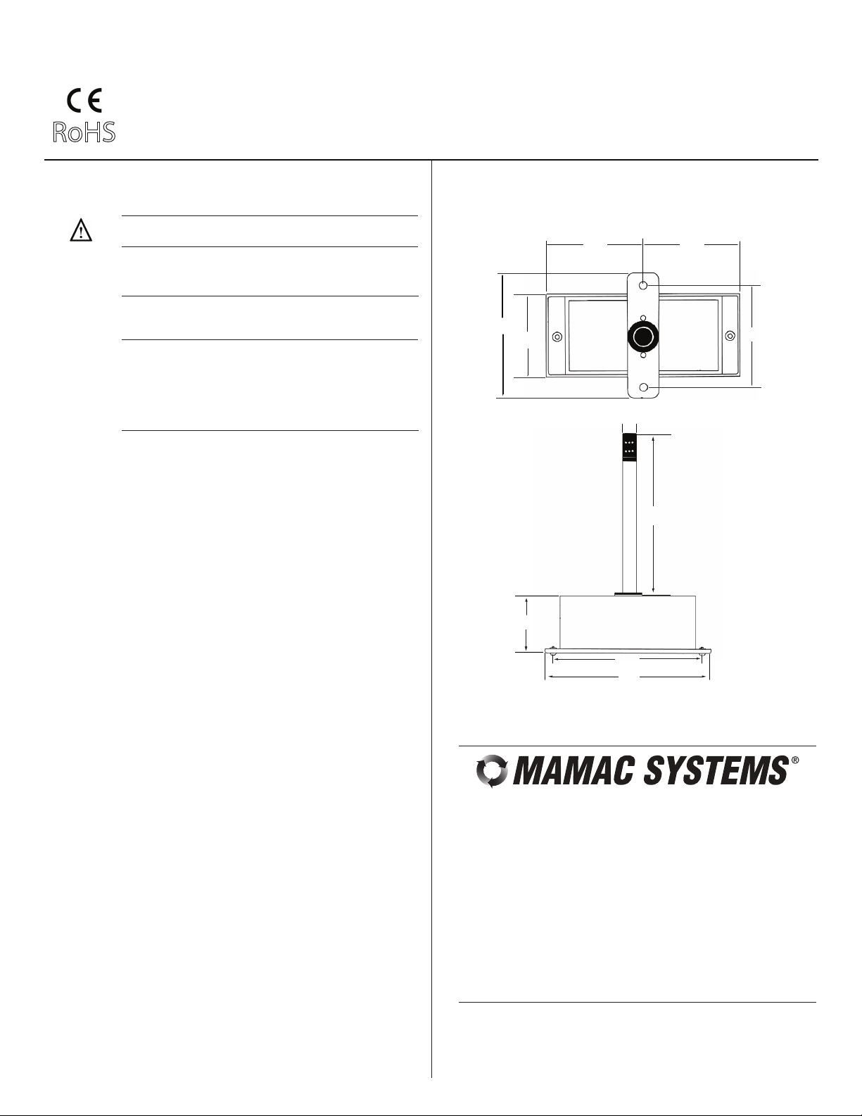
HU-226 (DUCT) - Refer to Figure 6 for mounting dimensions.
1. Drill 5/8” hole in appropriate location.
2. Mount transducer on a vertical surface with two #8
self-tapping screws (not provided).
3. Pull wires through knockout and make necessary connections (see wiring diagrams).
4. Replace cover and tighten Philips screws.
Use maximum 12 AWG wire for wiring terminals. Refer to
Figures 1, 2, 3, & 4 for wiring information and Figure 5 for dip
switch designations.
mA Output
Wiring HU-226 Units with mA Output
HU-226 Humidity Transducer with mA Output
TYPICAL APPLICATIONS (wiring diagrams)
Figures 1 & 2 illustrate typical wiring diagrams for the HU-226, 4-20 mA,
two-wire humidity transducers.
Figure 1 - Wiring for mA Output Humidity Transducer with External DC
Power Supply
mA Output Transducer Only
Humidity
Temp
Figure 2 - Wiring for mA Output HumidityTransducer where Controller or
Meter has Internal DC Power Supply
+
12-40 VDC Power Supply
+
Controller / Meter / Recorder
Input Signal
+
Common
Shield/Ground
Temp
Input
HU-226 humidity transducers are 4-20 mA output units powered with a
12-40 VDC supply.
The following describes the proper wiring of these humidity and temp sensors
with mA output:
HUMIDITY SENSOR:
1. Remove the terminal block by carefully pulling it off the circuit board.
2. Locate the [+] and [-] terminal markings on the board.
3. Attach the supply voltage to the [+] lead.
4. Connect the 4-20 mA output ([-] terminal) to the controller’s input terminal.
5. Ensure that the power supply common is attached to the common bus of
the controller.
6. Re-insert the terminal block to the circuit board and apply power to the unit.
7. Check for the appropriate output signal using a DVM set on DC milliamps
connected in series with the [-] terminal.
TEMP SENSOR:
1. Remove the terminal block by carefully pulling it off the circuit board.
2. Use shielded 18-22 AWG wire to connect temp sensor as shown in
Figures 1 & 2.
mA Output Transducer Only
Humidity
Temp
Caution: If you are using grounded AC, the hot wire must be on
the [+] terminal. Also, if you are using a controller without built-in
isolation, use an isolation transformer to supply the HU-226
transducer.
Caution: This product contains a half-wave rectifier power
supply and must not be powered off transformers used to power
other devices utilizing non-isolated full-wave rectifier power
supplies.
Caution: When multiple units are powered from the same
transformer, damage will result unless all 24G power leads are
connected to the same power lead on all devices. It is mandatory that correct phasing be maintained when powering more
than one device from a single transformer.
+
Controller / Meter / Recorder
Input Signal
+
Common
Shield/Ground
Temp
Input
Page 3
Page 3 of 4
RoHS
Model HU-226
Technical Information
TI.226-05
HUMIDITY / TEMP SENSOR
VDC Output
Wiring HU-226 Units with VDC Output
HU-226 Humidity Transducer with VDC Output
0 to 10 VDC
(Factory Default)
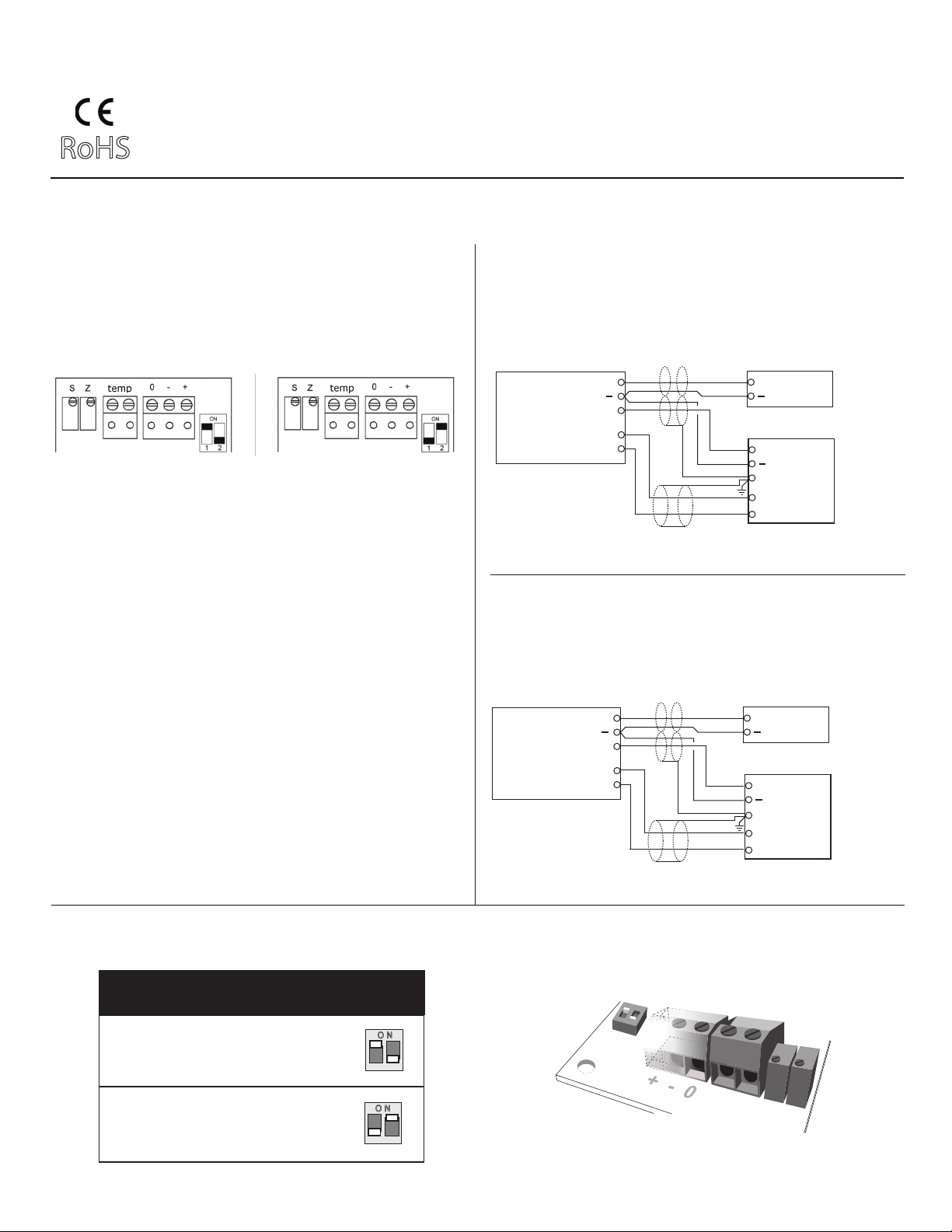
HU-226 humidity transducers with VDC output are field selectable 0-5 VDC or
0-10 VDC output and can be powered with either 12-40 VDC or 12-35 VAC.
The following describes the proper wiring of these humidity transducers with
VDC output:
HUMIDITY SENSOR:
1. Remove the terminal block by carefully pulling it off the circuit board.
2. Locate the [+], [-] and [O] terminal markings on the board.
3. Attach the power wires to the [+] and [-] terminals. The [-] terminal is
also the negative output terminal.
4. Connect the [O] terminal, which is the positive VDC output terminal, to
the controller’s input terminal.
5. Re-insert the terminal block to the circuit board and apply power to the
unit.
6. Check the appropriate VDC output using a voltmeter set on DC volts
across the [O] and [-] terminals.
TEMP SENSOR:
1. Remove the terminal block by carefully pulling it off the circuit board.
2. Use shielded 18-22 AWG wire to connect temp sensor as shown in
Figures 3 & 4.
0 to 5 VDC
TYPICAL APPLICATIONS (wiring diagrams)
Figures 3 & 4 illustrate typical wiring diagrams for the HU-226, 0-5/0-10
VDC output humidity transducers.
Figure 3 - Wiring for VDC Output when applied with External AC Supply
VDC Output Transducer Only 12-35 VAC Transformer
Supply
+
Humidity
Temp
Common
Signal
O
Controller / Meter / Recorder
Figure 4 - Wiring for VDC Output when applied with External DC Power
Supply
VDC Output Transducer Only 12-40 VDC Power Supply
Supply
+
Humidity
Temp
Common
Signal
O
Controller / Meter / Recorder
Hot
+
Neutral
Input Signal
+
Common
Shield/Ground
Temp
Input
+
Input Signal
+
Common
Shield/Ground
Temp
Input
Figure 5 - Dip Switch Settings for HU-226 VDC Output
HU-226
DUCT MOUNT
O N
0 to 10 VDC (default)
1
O N
0 to 5 VDC
1
ON
1
2
2
+ - 0
temp
Z S
2
Page 4
Page 4 of 4
RoHS
Model HU-226
Technical Information
TI.226-05
HUMIDITY / TEMP SENSOR
CHECKOUT DIMENSIONAL DATA
1. Verify that the unit is mounted in the correct position.
2. Verify appropriate input signal and supply voltage.
Figure 6 - HU-226 Humidity Transducer Dimensions shown in inches and
CAUTION: Never connect 120 VAC to these transducers.
millimeters (mm).
Never connect AC voltage to a unit intended for DC supply.
3. Verify appropriate configuration range.
Transducer
Operation
CALIBRATION
NOTE: The HU-226 is a highly accurate device. For
applications requiring a high degree of accuracy, the use of
laboratory-quality meters and gauges are recommended.
All units are factory calibrated to meet or exceed published
specifications. If field adjustment is necessary, follow the
4.00”
(101.6)
2.63”
(66.8)
instructions below.
Calibration of HU-226 mA/VDC Humidity Transducer
Field calibration instructions are provided with the following
precautions and advice:
1. Do not verify comparative RH with a sling Psychrometer.
There are far too many variables which induce errors into
this process. New HU-226 RH transducers are already
supplied with calibration.
2. Recalibration must be done in a controlled environment.
Relative humidity must be held stable while making any
adjustment.
2.81”
(71.37)
(12.7)
2.81”
(71.37)
3.25”
(82.55)
.50”
6.00”
(152.4)
MAINTENANCE
FIELD REPAIR
3. Verify the output from the device directly with calibrated
instrumentation and verify the RH with calibrated instrumentation, (NOT A CONTROLLER OUTPUT). With the correct
power applied and only a meter connected to the output of
the transducer, ensure that the output is proportional to the
true RH.
4. A) SINGLE POINT CALIBRATION:
[NOTE: SELECT EITHER OPTION 1 OR OPTION 2,
BUT NOT BOTH.]
Option 1. Select a controlled humidity environment
between 10 & 40% RH. Insure humidity
is stable and adjust zero trimmer (Z).
Option 2. Select a controlled humidity environment
between 40 & 70% RH. Insure humidity
is stable and adjust span trimmer (S).
B) TWO-POINT CALIBRATION: Select a controlled
humidity environment between 10 & 40% RH. Insure
humidity is stable and adjust zero trimmer (Z). Then
select a controlled humidity environment between
70 & 75% RH. Insure humidity is stable and then
adjust span trimmer (S).
Regular maintenance of the total system is recommended to
assure sustained optimum performance.
None. Replace with a functional unit.
2.00”
(50.8)
5.00”
(127.0)
5.63”
(143.0)
For Technical / Application Assistance call your nearest office
MAMAC Systems, Inc., reserves the right to change any specifications
without notice to improve performance, reliability, or function of our products.
WARRANTY
See Data Sheet for additional information.
TI.226-05
 Loading...