

Mallory Ignition 74186 User Manual

1
INTRODUCTION
Congratulations on the purchase of your new Accel Digital Nitrous Master Mind Processor. With over 20 years in designing and
producing state of the art EFI & Ignition systems, we are confident that this NO2 Mastermind will be a great addition to your car.
It is designed with you, the end user, in mind to make it easy for you to program and use.
State of the Art Technology: This system uses the latest available technology to offer unparalleled accuracy, repeatability, and reliability.
Easy to Read LCD Display with Touch Button Programming: Included with the Digital Nitrous Processor is a user friendly interface
that provides quick and accurate programming of Nitrous system directly from the driver’s seat.
Data Memory: There is no need to re-program the controller after the battery is disconnected. All data is stored in flash memory and
will be retained with no power applied to the controller.
NO2/Fuel Solenoids Outputs: The Processor provides separate NO2/Fuel Solenoid outputs. This allows you to have total control over
the flow time of the fuel solenoid.
(PROGRAM THE NO2/FUEL OFFSET TO GIVE THE FUEL A CHANCE TO START FLOWING BEFORE THE NO2 HITS, THUS
AVOIDING A BACK FIRE.)
DIGITAL NITROUS PROCESSOR
PART NO. 74186
INSTALLATION INSTRUCTIONS
FORM INSTR74186 11/09
ACCEL/DFI TECHNICAL SUPPORT 248.380.2780 www.accel-dfi.com
T
ABLE OF CONTENTS PAGE
Introduction . . . . . . . . . . . . . . . . . . . . . . . . . . . . . . . . . . . . . . . . . . . . . . . . . . . . . . . . . . . . . . . . . .1
Handheld Programmer Quick Menu Flow Chart . . . . . . . . . . . . . . . . . . . . . . . . . . . . . . . . . . . .2
Programming The Processor Using The Handheld Programmer . . . . . . . . . . . . . . . . . . . .3-4
Installation . . . . . . . . . . . . . . . . . . . . . . . . . . . . . . . . . . . . . . . . . . . . . . . . . . . . . . . . . . . . . . . . .5-6
Input/Output Chart . . . . . . . . . . . . . . . . . . . . . . . . . . . . . . . . . . . . . . . . . . . . . . . . . . . . . . . . . . . .6
Illustrations & Figures:
With HEI Distributor . . . . . . . . . . . . . . . . . . . . . . . . . . . . . . . . . . . . . . . . . . . . . . . . . . . . . . . . .7
With L98/LT1 Distributor . . . . . . . . . . . . . . . . . . . . . . . . . . . . . . . . . . . . . . . . . . . . . . . . . . . . .8
With FORD TFI Distributor . . . . . . . . . . . . . . . . . . . . . . . . . . . . . . . . . . . . . . . . . . . . . . . . . . . .9
With Inductive Pickup Distributor . . . . . . . . . . . . . . . . . . . . . . . . . . . . . . . . . . . . . . . . . . . . .10
With Honda Distributor . . . . . . . . . . . . . . . . . . . . . . . . . . . . . . . . . . . . . . . . . . . . . . . . . . . . . .11
With Universal Import Distributor . . . . . . . . . . . . . . . . . . . . . . . . . . . . . . . . . . . . . . . . . . . . . .12
With Aftermarket EFI . . . . . . . . . . . . . . . . . . . . . . . . . . . . . . . . . . . . . . . . . . . . . . . . . . . . . . .13
With Mallory/Hall Effect Distributor . . . . . . . . . . . . . . . . . . . . . . . . . . . . . . . . . . . . . . . . . . . .14
With Dodge Late Model Ignition . . . . . . . . . . . . . . . . . . . . . . . . . . . . . . . . . . . . . . . . . . . . . .15
Example NO2 RPM/Time Graph . . . . . . . . . . . . . . . . . . . . . . . . . . . . . . . . . . . . . . . . . . . . . .16
Using your Nitrous Processor . . . . . . . . . . . . . . . . . . . . . . . . . . . . . . . . . . . . . . . . . . . . . . . . . .17
Harness Schematic Overview . . . . . . . . . . . . . . . . . . . . . . . . . . . . . . . . . . . . . . . . . . . . . . .18-19
Warranty . . . . . . . . . . . . . . . . . . . . . . . . . . . . . . . . . . . . . . . . . . . . . . . . . . . . . . . . . . . . . . . . . . . . .5
2
www.accel-dfi.com ACCEL/DFI TECHNICAL SUPPORT 248.380.2780
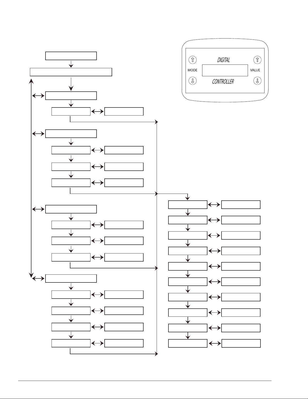
HANDHELD PROGRAMMER QUICK MENU FLOW
Engine RPM
NO2 Delivery
100% ON
NO2 Start RPM
1000 - 12700
RPM Control
NO2 Start RPM 1000 - 12700
NO2 Start %
100% RPM
5 - 90%
1000 - 12700
Time Control
NO2 Start RPM
NO2 Start %
Launch Time
1000 - 12700
5 - 90%
1 - 20 Seconds
NO2 Delay 1 - 20 Seconds
H/S Retard 0 - 25 Deg
RPM Switch
Main RPM Limit
1000 - 12700
1000 - 12700
AUX RPM Limit 1000 - 12700
RPM & Time
NO2 Start RPM
NO2 Start %
Launch Time
100% RPM
1000 - 12700
5 - 90%
1 - 20 Seconds
1000 - 12700
Safety RPM Limit
PWM Frequency
Trigger Volts 0 - 20v
Number of CyL
Fuel NO2 Offset 1 - 64 Ms
1000 - 12700
5 - 30 Hz
4 - 5 - 6 - 8 - 10 -12
3ACCEL/DFI TECHNICAL SUPPORT 248.380.2780 www.accel-dfi.com
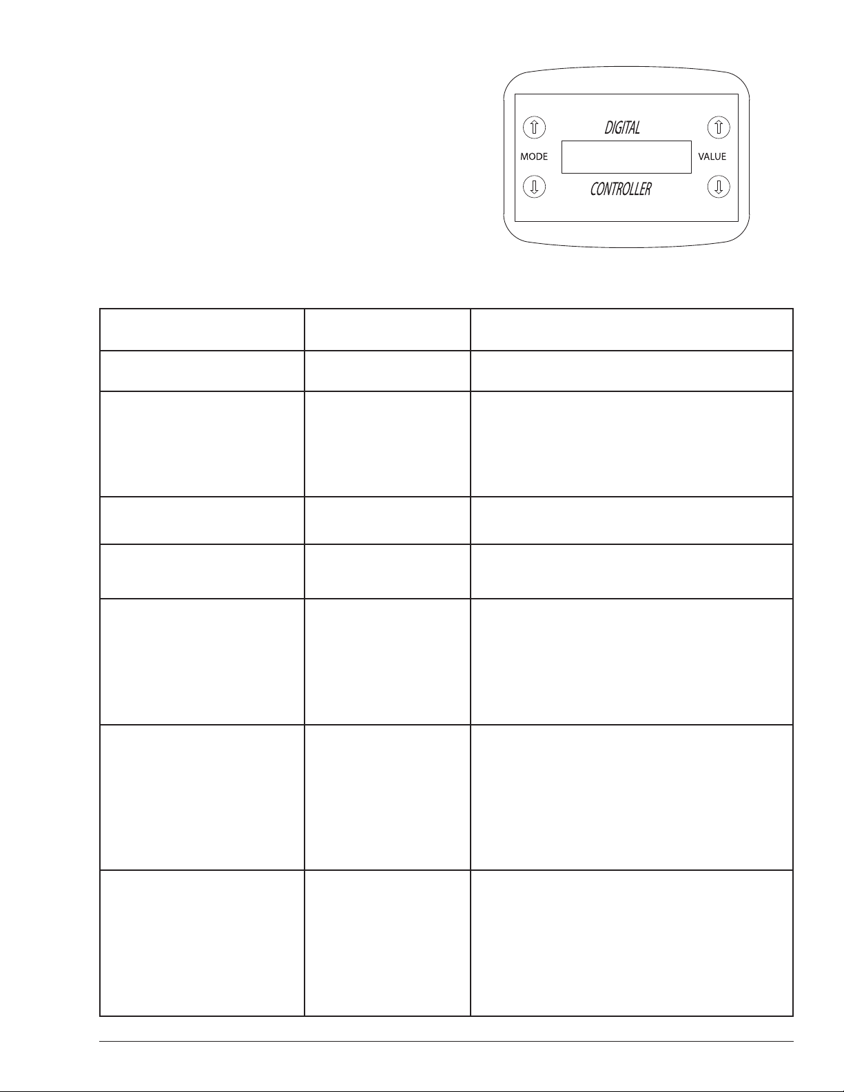
HANDHELD CONTROLLER INSTRUCTIONS
The controller has a 9-pin DSUB socket which plugs into the end
panel. It does not need to be plugged in for the ignition to run,
only to change the settings.
The control “modes’ are listed below. To set the modes, plug the
controller in and turn on the ignition. After a brief pause, the
controller display will light up. Use the “MODE” keys to select the
desired mode, and then use the up/down “VALUE” keys on the
right side to change the values.
Once you have finished with your settings, you can either turn the
power off and unplug the controller, or just leave it plugged in.
PROGRAMMING USING HANDHELD PROGRAMMER
Display Range/Resolution Explanation
Engine RPM NO2/Status 10 RPM Actual Engine RPM and NO2 Status
NO2 Delivery
Four choices of No2 Delivery.
1st 100% On (No time or RPM PWM)
2nd RPM Control
3rd Time Control
4th RPM & Time Control
100% ON
NO2 turns on full with any pulse width modulations on the
programmed thresholds are met.
NO2 Settings
Start RPM
1000-12700
RPM/100 RPM
RPM where the nitrous system starts working. Lowering the
value until the display says “OFF” disables this function.
RPM Control
1000-12700
RPM/100 RPM
The software linearly increases the duty cycle percentage as
a function of RPM between the two (N2O Start and N2O
100%) values. This RPM setting should be 1000 RPM above
the activation RPM.
NOTE:
Regardless of the nitrous settings, the nitrous
system is shut off 300 RPM before the main RPM limiter.
Time Control
.0 to 20.0 seconds/
.1 second increments
Launch time modulates the pulse width as a function of
time. This is useful when traction becomes a problem.
Once the arming and triggering conditions are met, the
launch timer modulates the solenoids to help with tire spin.
For example: If Launch time is set at 5 seconds and when
the NO2 activates, the pulsing of the solenoids will increase
as the time set decreases. (.1second 1% Flow 5 second
100% Flow)
RPM & Time
Control
1000-12700/
.1 – 20 Seconds
This mode is useful for a car with a loose converter or a
weak clutch. It prevents the user from driving through the
converter with the NO2 full on. It allows the user to have
complete control over ramping the power in, so that when
the NO2 is at 100%, the full power of the Nitrous hit is well
past the converter RPM threshold. (Example of this is on
page 18)

4 www.accel-dfi.com ACCEL/DFI TECHNICAL SUPPORT 248.380.2780
Display Range/Resolution Explanation
NO2 Delay 0 – 20 Seconds
The delay timer is used to delay the nitrous system from
engaging once the arming and triggering thresholds are
met. For example: if the system is armed (12v on the arming
input) and the Micro Switch/TPS and RPM input thresholds
are met, the system will wait for the amount shown in Delay
Time before activating the nitrous system. This delay only
occurs after the initial start of the process. If the Micro
Switch/TPS voltage falls below the set threshold, the nitrous
will shut off, but if it goes back above the set threshold, the
nitrous will start again immediately, with no delay. The
arming input is the reset for this function.
NO2/High Speed Timing Retard
0 – 25 Deg in 1
deg increments
This is the ignition retard setting that is used when the
NO2 is activated. Timing is pulled out to avoid detonation
that can cause engine failure. This feature offers a High
Speed Retard that can also be used to pull timing out when
NO2 is disabled. By applying 12V+ to Pin C Yellow Wire on
the 8 pin connector, the processor will retard the timing by
amount set.
RPM Switch
1000-12700
RPM/100 RPM
When the set RPM is reached, the output wire will be pulled
to ground (5 amps max) PIN G Orange Wire. When the RPM
drops 500 below the RPM switch setting, the switch will be
shut off. This prevents “chattering” when the RPM is not
stable. (Can be used to trigger a shift light, secondary
fuel pump, Data acquisition system, etc.)
Main RPM Limit
1000-12700
RPM/100 RPM
This is a fast-acting pulse-by-pulse RPM limiter. It does not
average the incoming period, so it will be rough when the
engine is unloaded, but will control RPM very accurately.
Auxiliary RPM Limit
(Two Step)
1000-12700
RPM/100 RPM
Activated by applying 12v on the Pin D Green/White wire of
the 4 wire connector marked “AUX” input. Same operation
as the Main RPM Limit. (Used mainly as a 2 Step).
Safety RPM 1000-12700
This is used as a NO2 shutoff RPM set point on deceleration.
(Example: If the NO2 Trigger relay or micro switch fails to
disengage the NO2 after you are off the throttle, the Safety
RPM will shutoff the NO2 once below the set RPM.
PWM frequency 5 – 30 Hz / 1 Hz steps
This function is how often per second the solenoids are
cycled. Lower numbers are easier on the solenoids, but can
result in “shuddering”, especially at lower speeds and low
duty cycles. Higher PWM frequency is better for smooth
delivery, but is much harder on the solenoids.
NOTE: Accel/DFI is not responsible for solenoid damage.
Trigger Volts 0 to 20V /.1 volts
After arming the system, this is used as a “start” input from
a Micro switch – Push Button or TPS.
NOTE: If the value is set to zero, the system will start
delivering nitrous when the arming input and RPM setting
is reached. ( We recommend that you use a Micro switch
with this system)
Number Of Cyl Selection 4, 5,6,8,10,12 Cyl. Pick the number of cylinders for your application.
Fuel/N2O offset 1 to 64 Ms / 1 Ms
This is the amount of time that the system delays the
activation of the N2O solenoid after the fuel solenoid, to
give the fuel a chance to start flowing before the nitrous
hits, thus avoiding a lean spike.
PROGRAMMING USING HANDHELD PROGRAMMER CONT’D

5ACCEL/DFI TECHNICAL SUPPORT 248.380.2780 www.accel-dfi.com
INSTALLATION
WHAT YOU SHOULD KNOW
Please read these instructions carefully before installing your
Digital Nitrous Processor.
Important Tips
• Do not use solid core spark plug wires with this unit. It contains
digital electronics and will NOT function correctly with solid
core wires.
• Do not install harness or run Points Input / Output wires near
spark plug wire or ignition coil. Mount the Processor as far
away from secondary ignition components (coil, ignition wires,
etc.) as physically possible.
• This unit is not water resistant or water proof, we suggest that
it is mounted in the passenger compartment so as not to get
wet from rain, car washing or a liquid of any type!
• The Handheld programmer buttons are very delicate and can
be damaged by misuse and/or carelessness. Programmers that
have been determined to be damaged due to neglect will NOT
be covered under warranty.
Safety Tips, Please Read
• It is the responsibility of the purchaser to follow all guidelines
and safety procedures supplied with this product and any other
manufacturer’s product used with this product.
• Follow all recommended safety guidelines from this and other
manufacturer’s installation guides.
• It is also the responsibility of the purchaser to determine
compatibility of this device with the vehicle and other components.
• ACCEL DFI Corporation assumes no responsibility for damages
resulting from accident, improper installation, misuse, abuse,
improper operation, lack of reasonable care, or all previously
stated reasons due to incompatibility with other manufacturer’s
products.
• ACCEL DFI Corporation assumes no responsibility or liability
for damages incurred from the use of products manufactured
or sold by Accel DFI Corporation on vehicles used for
competition racing.
• ACCEL DFI Corporation neither recommends nor approves the
use of its products on vehicles which may be driven on public
highways or roads, and assumes no responsibility for damages
incurred from such use.
• It is the purchaser’s responsibility to check the state and local
laws pertaining to the use of Nitrous Oxide for racing applications.
ACCEL DFI Corporation does not recommend nor condone the
use of its products for illegal street racing.
INSTALLATION OF THIS PRODUCT SIGNIFIES THAT YOU HAVE
READ THIS DOCUMENT AND AGREE TO THE TERMS STATED WITHIN.
Due to the technical nature of ACCEL DFI products, we are unable
to answer technical questions via the Internet. If you have any
questions, Please call the ACCEL DFI Technical Support hotline.
Tech Line: 1-248-380-2780 from 8:30 am – 6 pm, MondayFriday, Eastern Standard Time.
Please fill out and mail your warranty card.
WARRANTY
FACTORY DIRECT LIMITED WARRANTY. ALL ACCEL/DFI
PRODUCTS* ARE WARRANTED AGAINST DEFECTS IN MATERIALS
OR WORKMANSHIP. ACCEL/DFI LIABILITY UNDER THIS WARRANTY
SHALL BE LIMITED TO THE PROMPT REPAIR CORRECTION OR
REPLACEMENT OF ANY DEFECTIVE PART OF THE PRODUCT
WHICH ACCEL/DFI DETERMINES TO BE NECESSARY. THIS LIMITED
WARRANTY IS TO THE ORIGINAL PURCHASER FOR AS LONG AS
HE OR SHE OWNS THE VEHICLE ON WHICH THE PRODUCT IS
ORIGINALLY INSTALLED, PROVIDING ALL THE INFORMATION
REQUESTED IS FURNISHED. YOU MUST RETAIN A COPY OF YOUR
ORIGINAL SALES INVOICE OR RECEIPT. WITHOUT PROPER
DOCUMENTATION, THIS WARRANTY IS VOID.
RESOLD UNITS ARE NOT COVERED UNDER THIS WARRANTY.
CAUTIONS AND WARNINGS
1. Always follow safety & installation guidelines and precautions
when installing this and any other related component.
2. Always remove both battery cables when installing new
electrical components and/or wiring.
3. Always use Circuit protection (Fuses) where required.
4. Wire in all your connections with the Processor disconnected.
5. Connect ground wires directly to battery negative terminal or
at battery negative cable end.
6. Test system for proper operation after completing installation.
PARTS INCLUDED
1 ACCEL/DFI Digital Nitrous Processor
1 Handheld Programmer
1 Handheld Programmer Cable
1 8-way Processor Control Harness
1 4-way Processor Power Harness
1 Magnetic Pickup Harness
1 NO2 Solenoid Harness
RECOMMENDED PARTS NOT SUPPLIED
Parts Part #
1 NO2 Single Stage System
1 Accel/DFI 6A or DFI 6A 75606 - DFI Pro 7 75609
PRO 7 CD Ignition Box
1 Accel DFI “E” Core DFI “E” Core 75607 - DFI Pro 7 75608
or Pro 7 Coil
1 Micro Switch
1 Lighted Toggle Switch
1 Firewall Rubber Grommet
(To keep wires from chafing
on metal edge)

www.accel-dfi.com ACCEL/DFI TECHNICAL SUPPORT 248.380.27806
INSTALLATION – HOW TO
Start by locating a spot in the passenger compartment (Recommended) to mount the NO2 Processor. Keep it away from any moisture
spots and from any area where it can be damaged by the passengers. DO NOT install it in an area where it can get very hot, the
internal components require good ventilation.
1. Mount Processor
2. Drill hole through fire wall (Check Grommet Center OD for correct drill size) directly behind engine. Install rubber grommet. (Keep
hole away from exhaust headers)
3. Pull harness through fire wall, (Do Not Plug Harness in processor at This Time).
4. Run the wires to their components in the engine compartment, (Example: NO2 Solenoid Wires, 6A CD Box, Battery + -, MAG Trigger.)
5. Using wire chart on page 8 and figure 1 through 9 on pages 09 -17, hook up processor to vehicle components.
6. After all wiring and installations are done; plug all connectors together at the Processor.
NO2 Acc. Harness
8 Pin Connector Wire Color
Pin A = RPM input (Points) White Trigger Signal Input
Pin B = NOT Used
Pin C = High Speed Retard Yellow Requires 12V+ Input
Pin D = Spark Trigger RPM Out DK Blue To CD Box (Accel/DFI 6A)
Pin E = NO2 Enable (0-20 Volt+) Gray To Micro Switch or TPS
Pin F = Sensor Return (TPS) Gray/Red To TPS Sensor Return
Pin G = RPM Switch Out (Ground) Orange Example: Shift Light ground
Pin H = Master Arm Input 12V+ Blue/Pink NO2 Arming Switch 12V+
NO2 Power Harness
4 Pin Connector
Pin A = Ignition 12 Volt Batt+ Red To + 12 Battery
Pin B = Ground Black To - Battery
Pin C = Tach Output LT Green To Tach Input
Pin D = AUX RPM Input 12V+ Green/White To trans brake +12 button
NO2 MAG Pickup Harness
2 Pin Connector
Pin 1 = MAG + Pickup Purple Distributor IPU +
Pin 2 = MAG – Pickup Green Distributor IPU -
NO2 Stage 1
2 Pin Black Connector (Note: 25 AMPS MAX Rating per Solenoid)
Pin A = Stage 1 Fuel Out (Ground) White/Red To Fuel Solenoid Ground
Pin B = Stage 1 NO2 Out (Ground) White/Blue To Nitrous Solenoid Ground
SINGLE STAGE INPUT/OUTPUT DIAGRAM FOR ACCEL/DFI DIGITAL NO2 PROCESSOR
SYSTEM VOLTAGE SPECS
Voltage Operating Range: 12 to 16 Volts
Nitrous Solenoid Grounds: 25 AMPS Maximum for 15 Seconds
Fuel Solenoid Grounds: 25 AMPS Maximum for 15 Seconds
Systems enable inputs: 12 Volts
 Loading...