

Page 1

Installation Manual
For The Ford ACCEL
Digital Fuel Injection
Engine Management
System
Part #74030
The Mr. Gasket Performance Group
Cleveland, Ohio
216.398.8300
www.mrgasket.com
Page 2

ACCEL/DFI
Prior to starting the installation of your ACCEL DFI system,
read this manual carefully!!
Contents Pages
Introduction 1
I) Obtaining Your Manifold 2
II) Setting Up Your Manifold 2
III) Mounting Your ACCEL ECM 4
IV) Injector Harness Installation 5
V) Main Wire Harness Routing And Connections 5
VI) Choosing Your Distributor 9
VII) Fuel Pump Mounting and Fuel Line Installation 13
VIII) Mounting The Oxygen Sensor 19
IX) Air Cleaner Assembly 20
X) Starting The Vehicle 20
XI) Optional Items 21
XII) Trouble Shooting Guide 23
Some parts are not legal for sale or use in California or on
any pollution-controlled motor vehicle.
ii
Page 3

ACCEL/DFI
INTRODUCTION
CONGRATULATIONS! You have just purchased the finest
engine management system available. EFI control is an
exact science that ACCEL has made simple. This manual is
written to assist you with the installation of your new
system to your FORD application. Please read this manual
carefully.
Prior to starting your installation, please verify the contents
of your ACCEL DFI package. You should find the following
components:
Quantity Component
(1) Electronic Control Module (ECM)
(1) Main Wiring Harness (MWH)
(1) Injector Wire Harness (IWH)
(1) Manifold Absolute Pressure (MAP) sensor
(1) Heated Oxygen Sensor with mounting nut
(1) Coolant Temperature Sensor (CTS)
(1) 6 way to 4 way TFI adapter harness
(1) Throttle Position Sensor (TPS)
conversion connector
(1) Idle Air Control (IAC) Motor
(1) Idle Air Control (IAC) Motor Housing
(1) IAC Motor Housing Adapter Plate
(1) IAC Adapter Plate with gasket and screws
If your are missing any item , please contact your dealer
immediately.
1
Page 4

ACCEL/DFI
Although this package is designed to allow you to convert
a carbureted engine to fuel injection or allow you better
control over your present fuel injected engine, it does not
include the hydraulic portion of the installation. If you need
a fuel pump, filter, fittings, etc. contact your local ACCEL
EMIC center for the proper ACCEL DFI part numbers for
your application.
I. OBTAINING YOUR MANIFOLD
Currently ACCEL DFI only has manifolds for Chevrolet
applications, for your Ford application you may use an
OEM or aftermarket fuel injection manifold. Talk to some of
our ACCEL DFI’s EMIC centers for fabricating or modifying
a carbureted style manifold for your application. ACCEL
DFI EMIC Centers can also sell, install, and tune all ACCEL
DFI products. For the nearest dealer to you please call:
1.800.992.2235.
II. SETTING UP YOUR MANIFOLD
Prior to installing your manifold make sure that all gasket
surfaces are clean. ACCEL recommends using a 180 degree
thermostat in most applications. Place your thermostat and
gasket onto your manifold, put your thermostat housing
onto the manifold and bolt in place. When installing your
fuel injectors, be careful not to cut the O-Rings. A small
amount of oil on each O-Ring will aid in the assembly.
Please reference a service manual for proper torque
sequence and vacuum line routing. If this is a custom manifold,
please contact your fabricator for this information.
NOTE: It is recommended at this point to use a hole saw
(i.e. Green Lee punch) to put two (2) 1-5/8” diameter holes
in the firewall to accommodate the main wiring harness.
Please refer the figure below.
2
Page 5
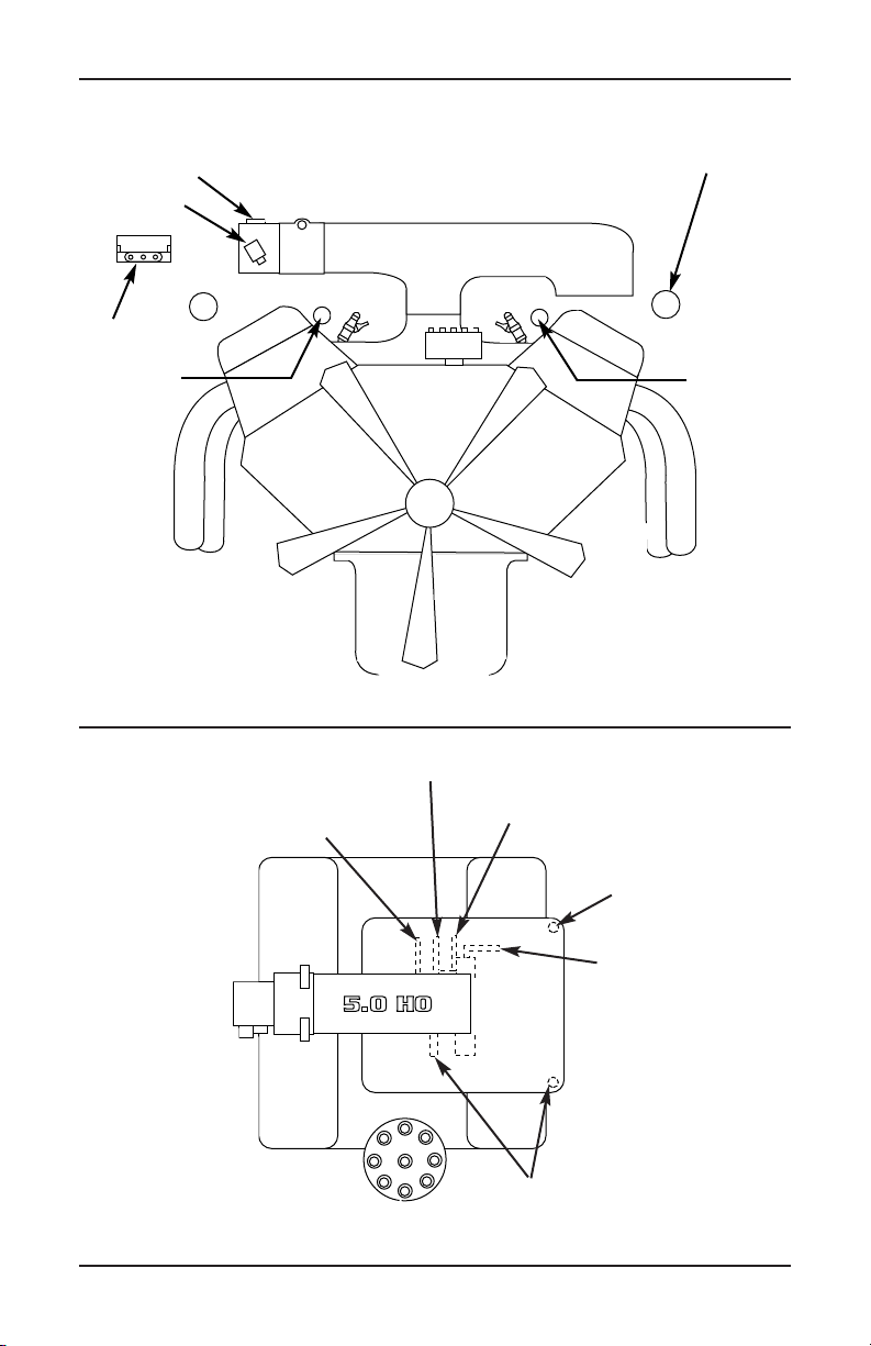
TPS Sensor
IAC Motor
MAP Sensor
Main Wire
Harness
ACCEL/DFI
1-5/8 Hole thru firewall
for grommet in main
harness - 2 places
Main Wire
Harness
Manifold Vacuum
to MAP Sensor
Manifold Vacuum to
Pressure Regulator
Manifold Vacuum to Automatic
Transmission Modulator
Additional Manifold Vacuum
Sources. (Plug all vacuum
sources not used)
PCV Valve
Vacuum Line
Manifold Vacuum
to Power Barke
Booster
3
Page 6
ACCEL/DFI
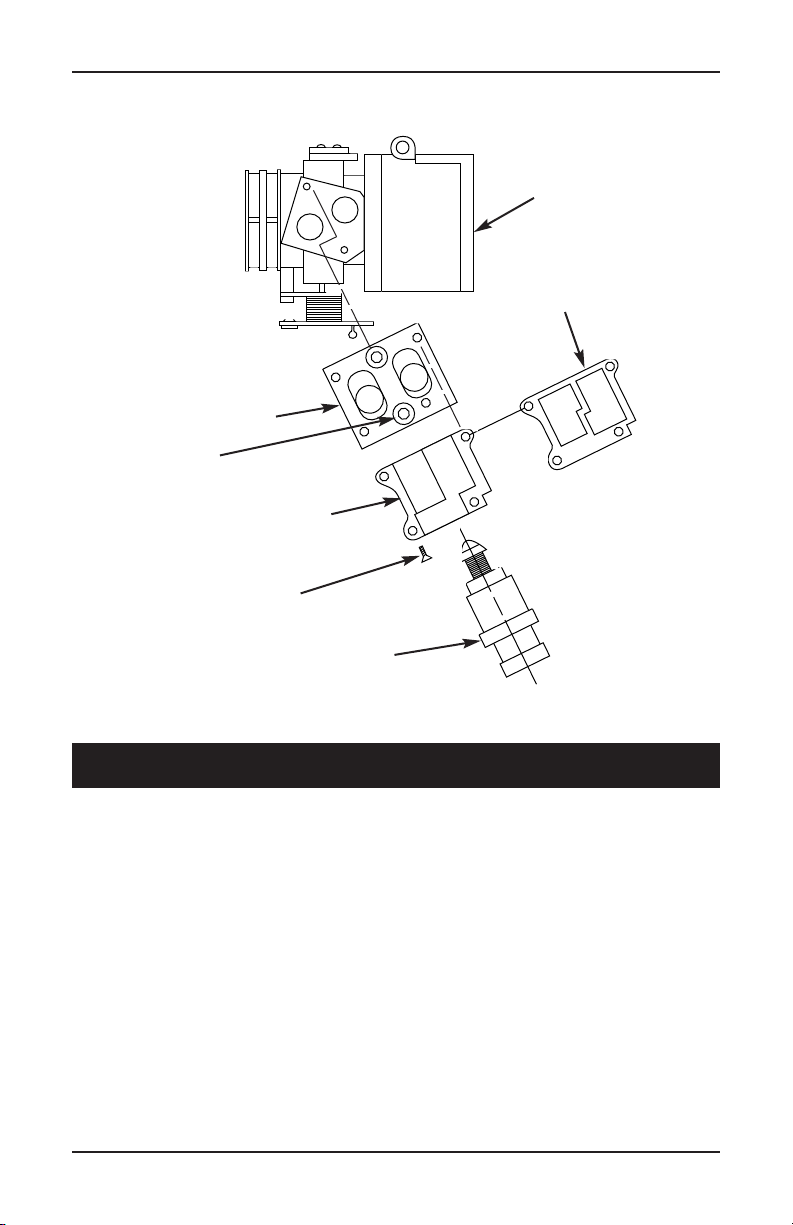
IAC Adapter Plate
Bolt Size
IAC Housing
Bolt Size
Throttle Body
IAC Gasket
IAC Valve
III. MOUNTING YOUR ECM
The ECM comes with three (3) mounting tabs designed for
a #8 sheet metal screw. It is recommended that you mount
the ECM in the passenger side kick panel. If the kick panel
has an air vent incorporated into it, DO NOT mount the
ECM here. This unit is not waterproof and therefore needs
to be mounted in a location free of moisture. The alternate
locations are in the dash board and behind the glove box.
NEVER MOUNT THE ECM IN THE ENGINE
COMPARTMENT!
4
Page 7
ACCEL/DFI
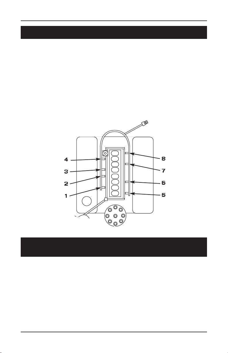
IV. INJECTOR HARNESS INSTALLATION
This ACCEL DFI system is simultaneous double fire,
therefore it does not matter what injector connector goes
to what injector. For your convenience the connectors are
paired in sets of two, similar to the way the injectors are
mounted in the manifold. Lay the injector harness so that it
lays naturally on the manifold. Clip the connectors onto the
fuel injectors making sure that the metal clips snap into
place.
4
3
2
1
8
7
6
5
V. MAIN WIRE HARNESS ROUTING
AND CONNECTIONS
An overview diagram of the main wiring harness is shown
at the end of this section. Please reference this when making
the connections between the ECM and the corresponding
sensors/components. The harness can be routed and connected as follows: Begin by connecting the 32 pin and 24
pin ECM connectors to the ACCEL DFI ECM, making sure
that the tabs snap into place. Then route the longer of the
5
Page 8

ACCEL/DFI
two legs through the drivers side firewall hole that you cut
in step two followed by the shorter leg though the
passenger side firewall hole. Continue pulling the harness
legs through the firewall until the rubber grommets seat
themselves in the firewall. Once the grommets have been
properly seated into the firewall, each leg can be routed
between the manifold and the valve covers.
The drivers side leg will contain connectors for the following:
• MAP (3-pin green male connector)
• Computer Controlled Ignition (4-pin male black
connector, for a TFI you will use the TFI adapter)
• ESC (purple wire, bare lead)
• Air (2-pin gray connector)
• Coolant (2-pin black connector)
• TPS (3-pin black male connector)
Make sure to connect the switched +12 volt wire (long pink
wire with a female spade connector) to a switched ignition
accessory in the fuse box. The switched ignition accessory
MUST maintain 12 volts during cranking. If it does not, the
vehicle will not start.
NOTE: If you are not controlling timing with the ACCEL
DFI ECM (using a non-computer-controlled ignition system
such as a points distributor) you will not be using the
computer-controlled ignition connector (4-pin male black
connector) or the ESC connector (purple wire with bare lead).
The passenger side harness leg will contain the following
sensor connections:
6
Page 9

ACCEL/DFI
• Oxygen (3-pin female black connector)
• Injector (5-pin round white connector)
• Tach pick-up (1-pin brown connector)
• Fuel pump (bare lead, red wire with white stripe)
• IAC (4-pin square male black connector)
Connect each to the appropriate sensor using the diagram
at the end of this section. If you need to lengthen the fuel
pump wire to reach your fuel pump, make sure to use at
least 14 gauge wire, soldering and heat shrinking the
connection between the two wires. Finally be sure to
connect both the positive and ground terminals on the main
wiring harness DIRECTLY to the battery. If you fail to do
this, intermittent and unusual problems may occur.
NOTE: If you are controlling timing with the ACCEL DFI
ECM (using a computer-controlled ignition system, TFI,
etc.) the Tach pick-up will not be used. If you connect the
Tach pick-up and the computer-controlled ignition connector
at the same time, your ACCEL DFI ECM will cancel them
both out resulting in a no spark (no RPM signal) situation.
In many cases this will also damage your ECM.
At this time you can connect your User Interface Module
(UIM, or Power Tuner) to the MWH by connecting the
6-way connector (located near the ECM connectors) to the
6-way connector on the UIM. If you did not order a UIM
there is nothing for you to do with the 6-way connector on
the MWH. If using a UIM mount the unit with two (2) #8
sheet metal screws or 20 pan head screws with nuts, in a
location convenient to the driver.
7
Page 10

ACCEL/DFI
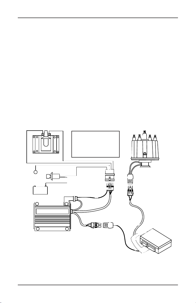
Connector to Main
Firewall
Grommet
3 PIN Green
Connector to
MAP Sensor
3 PIN Black
Connector to
TPS Sensor
4 PIN Black
Connector to
IAC Motor
5 PIN Grey
Harness
5 PIN Black
Connector to Injector
Harness (Male)
Pink Wire to 12V
Switched on Fuse Box
3 PIN Black
Connector to O
Sensor
Red/White to Fuel
pump Positive (+)
2 PIN Black
Connector to Water
Temp Sensor
Only connect white wire to
negative (–) side of ignition coil
when using a non-computer
controlled distributor. See
installation instructions if using
Mallory or ACCEL 300+
2
2 PIN Grey
Connector to
Optional Air
Temp Sensor
4 PIN Black
Connector to be used
only with a computer
controlled distributor
To 6 PIN Jumper Harness to interface
between 4 PIN Main Wiring Harness
Connector and 6 PIN Thick Film Module
(TFM) Connector on Computer
Controlled Distrubutor
Only connect black wire to
negative (–) side of ignition coil when
using a computer controlled distributor.
See installation instructions if using
Mallory or ACCEL 300+
8
Red wire
DIRECTLY to Battery
Black, Purple/Black,
Black/White wire
MUST GO DIRECTLY
to Battery Ground (-)
MUST GO
Positive (+)
+
-
Page 11

ACCEL/DFI
VI. CHOOSING YOUR DISTRIBUTOR
NON-COMPUTER-CONTROLLED IGNITION
If you are using a stand-alone magnetic pick-up distributor,
points distributor, etc., the Tach pick-up (1-pin brown
connector) must be used. Connect this lead to the negative
side of the coil. If the brown connector must be removed,
make sure not to remove the 39K ohm resistor which is
located 3” away from the existing connector.
NOTE: If you are using an aftermarket ignition enhancer
box (i.e. ACCEL 300+, Mallory Hyfire) the MWH’s Tach
pick-up connector MUST be connected to the enhancer
box’s Tach output signal. It is also necessary to remove the
39K ohm resistor from the Tach pick-up wire. It is located 3”
from the end of the Tach pick-up lead. DO NOT connect
this lead to the negative side of the coil if using an enhancer
box. This can result in ECM damage.
ACCEL strongly urges the use of a good quality suppression
wire such as ACCEL 300+ or ACCEL RFI Suppression
Wires. We have encountered problems (including not
suppressing electrical noise) with various ignition wires
available on the market such as helically-wound or solid
core. The use of these wires may interfere with the
operation of the ECM. Further, some high energy aftermarket
ignition units also produce electrical fields which will
interfere with the ECM’s operation. Use of these units is
strictly at the risk of the owner. Call ACCEL for
recommendations of ignition system compatibility.
9
Page 12

ACCEL/DFI
The total advance to which you set the engine will depend
upon the engine you have. Vacuum advance should be
controlled with the EGR port, which is located before the
throttle blades. ACCEL DFI recommends a distributor with
an adjustable vacuum advance. Once the total advance is
set, connect the vacuum line to the canister. Adjust the canister to maintain 20-26 degrees with a hot idle at 800 RPM.
Again, this is ACCEL’s recommendation, depending upon
compression ratio and cam profile, you may have to
decrease this to avoid detonation.
COMPUTER-CONTROLLED IGNITION
If you are using a TFI distributor you will need to connect
the TFI adapter harness to the 4-pin black ignition control
connector on the MWH. After doing so you can plug the
6-way end into your TFI distributor; the 1-pin black
connector will go to the negative side of your ignition coil
or points/lead of your enhancer box. You can also control
timing by using a magnetic pick-up distributor or crank
trigger. In order to do so you must get a modification done
to your ACCEL DFI ECM (ACCEL DFI part number
74043-I). This modification will come with the necessary
wiring (this wiring with replace the TFI adapter) but will
not come with an enhancer box that is required. If you will
need this modification, contact ACCEL DFI for further
instructions and a shipping address.
In order to set the initial timing, the ignition bypass
connectors (two 1-pin connectors) incorporated into the
ignition control leg must be disconnected. With the engine
running hot at 800 RPM, manually adjust the distributor to
6 degrees BTDC. Once adjusted, reconnect the ignition
bypass line. As soon as you connect the bypass line the
ACCEL DFI ECM regains control of the timing. The spark
10
Page 13

Distributor
PIP
SPOUT
BLANK
SWITCHED GN
COIL (–)
GND
Thick Film Module Jumper
Harness to be connected
between Distributor and
Main Wiring Harness
One Way Female
Connector
One Way Male Connector
provided with kit
ACCEL/DFI
4 Way Connector on
Main Wiring Harness
DFI 4 PIN
A – EST (B–1)
B – REF (A–2)
C – Switched GN (D–7)
D – GND (A–12)
–
COIL
+
Push to
insert
Seal
12-16 GA Wire
Male Terminal
Instructions for assembling
1,2,3,4 or 6 Way electrical
connectors
Connector
Female Terminal
Push to
insert
Seal
12-16 GA Wire
11
Page 14
ACCEL/DFI
curve is pre-programmed into the ECM from ACCEL DFI. It
has initial timing of 20 degrees BTDC and a total timing of
34 degrees BTDC in by 3000 RPM. The timing curves, as
well as all other tables in the ECM, can be adjusted to better
suit your engines requirements using ACCEL DFI’s
calibration software “CALMAP”.
NOTE: If an aftermarket ignition enhancer box is used (i.e.
ACCEL 300+, MALLORY HyFire), the TFI distributor can be
wired as described by the manufacturer of the enhancer
box. However, if you are controlling timing with a magnetic
pick-up distributor or a crank trigger, refer to the
illustration below.
-+
MSD Purple = (-)
ACCEL Red = (-)
Coil
Orange = (+)
Green = (+)
Black = (-)
White = (+)
12
Ground
ACCEL 300+
Key
Battery
Purple
Black
(-)
Distributor
Orange
(+)
Change
P1-B1 to
P1-B7
ACCEL
DFI
Page 15

ACCEL/DFI
VII. FUEL PUMP MOUNTING
AND HIGH PRESSURE LINE INSTALLATION
ACCEL DFI currently has two high pressure fuel pumps
available: part number 74701, an external mount fuel pump
which can support up to 450 horsepower @ 45 PSI, and part
number 74702 which can support up to 840 horsepower @
45 PSI. This fuel pump can be mounted in the fuel tank or
on the frame rail. You can use part number 74710 to mount
this pump onto your frame rail. Regardless of the fuel
pump used, be sure to mount your fuel pump near the tank
at a point of fuel level and in a protected area. System
components must also be protected and shielded from
exhaust and engine compartment heat as well as from
potential road damage.
FUEL PUMP WIRING
The fuel pump requires a +12 volt source. If your vehicle
was originally an EFI vehicle and already has a fuel pump
installed, you still MUST use the ACCEL DFI wiring.
Connect the +12 VDC side of the fuel pump to the ACCEL
DFI main wiring harness, using the red wire with white
tracer. The fuel pump relay is already an integral part of the
main wiring harness and is controlled by the ECM, therefore
no wiring is necessary for the relay. A pump will draw
between 4 and 8 amps of current depending on size and
fuel system pressure, so 14 gauge wire should be used from
the pump to the red wire with white tracer. Also, be sure to
solder the connection between these two wires. The ground
for the fuel pump can be at any clean, paint-free point on
the chassis to the negative (-) terminal of the fuel pump.
Make sure that wiring between the fuel pump and the
engine compartment does not hang below the vehicle, interfere
with rotating parts, or become exposed to excess heat.
13
Page 16

ACCEL/DFI
MECHANICAL PUMP REMOVAL
If your engine was carbureted, be sure to either cap off the
fittings on your mechanical pump or remove the pump and
cover the opening with a block off plate.
HIGH PRESSURE FUEL FILTER MOUNTING
Locate the high pressure fuel filter at the outlet of the high
pressure fuel pump on the frame rail. It is recommended to
place a filter between the fuel tank outlet and the pump
inlet if the pickup tube in the tank does not have a filter.
Failure to do so can result in fuel pump damage. ACCEL
DFI high pressure filter, part number 74720 requires 3/8”
Saginaw fittings. If your filter does not have these fittings
you can use part number 74721, these adapter fittings will
fit the 74720 filter and allow you to use a 6AN fitting.
ROUTING HIGH PRESSURE FUEL HOSE
At this point the high pressure circuit of the fuel system can
be plumbed (refer to diagram at the end of this section). If
the existing fuel supply line cannot sustain 150 PSI fuel
pressure (ACCEL recommends a fuel line rated to at least
330 PSI), then it must be replaced with high pressure fuel
line/tubing. Remember, with a carburetor, your fuel system
operated at about 6 PSI. However, with fuel injection, the
system operates around 50 PSI of fuel pressure. Never take
any chances. If in doubt, replace the hose. You will need a
minimum of 3/8” ID supply line and 5/16” ID return.
14
Page 17

Page 18

ACCEL/DFI
DUAL FUEL TANKS
It is important to note that for vehicles with two fuel tanks
and/or a class “A” RV, it is highly recommended that a
boost pump be installed in each tank and feed though a
multi-port switching valve, especially when operating in
hot climates. Boost pumps used on such vehicles as a 1985
Ford F-250 5.0L EFI will work well for this type of application. The switching valve from a 1984 Ford Diesel or a 1986
Chevrolet C-10 (305 CID) will work well in dual tank applications. Dual tank equipped vehicles must be plumbed to
return excess fuel to the tank which is supplying fuel to the
EFI system to avoid tank overflow problems. The remotelyactivated dual tank three-way valves described above will
work well in these applications.
A NOTE TO THE INSTALLER
There seems to be a misunderstanding with some people
that a fuel pump “produces pressure”. This is not accurate.
What actually happens is the pump produces fuel flow at a
given system pressure which is dictated by the pressure
regulator. The pressure regulator has a spring which is
preset to provide a certain system pressure, i.e. 45 PSI. The
regulator opens as the pressure in the fuel line increases
due to the flow of fuel provided by the pump.
As the pressure drops, due to bypassing of fuel to the tank,
the regulator closes at a pressure of 45 PSI (this pressure is
variable on adjustable regulators). This process will begin
again as pressure raises. Therefore, the pressure regulator is
a dynamic modulating device which always tries to seek its
preset pressure.
16
Page 19

ACCEL/DFI
SENDING UNIT MODIFICATIONS
To install a return line in your tank, remove the sender
assembly from the fuel tank and drill a 5/16” hole through
the top of the flange. Be sure to give yourself enough room
to weld the tube into place, welding procedures are
discussed later in this section. ACCEL DFI jumper line kit,
part number 74731, will supply you with this line as well as
other lines that you may need. Pre-bend a piece of 5/16”
fuel line so that the in-tank portion end is 2” from the
bottom of the tank and away from existing outlet tubes (See
figure at the end of this section). Ensure that the installation
of this tube does not interfere with any other components
on the tank unit. Clean the unit with soap and water prior
to the next step. Seal and secure the return line to the flange
by welding or brazing with low heat so that flange warpage
does not occur. Also make sure that applied heat does not
damage the sending unit wires or wire seals. Clean the
welded area and check for cracks or holes in the flange,
tubes or welded area.
Check the condition of the filter sock on the pick-up tube.
If the sock is torn or contaminated, replace it. Again, if you
are not using a filter sock in your application then install a
filter between the fuel tank supply line and the inlet side of
your fuel pump.
17
Page 20

ACCEL/DFI
5/16 Fuel Return Line Must Be
Added to Non-Fuel Injected
Vehicles. See Installation
Manual for Proper Installation
Braze Tube to Flange
making Sure Not to
Melt any Rubber or
Plastic Components
Top of Tank
Return Line
2"
Bottom of Tank
Existing Wire Harness
High Pressure Feed
Vapor Vent
Emissions/Canister
RETURN FUEL LINE INSTALLATION
If your vehicle was originally equipped with a carburetor,
you MUST run a 5/16” ID (inner diameter) or larger return
line from the engine (fuel pressure regulator) to the fuel
tank. Some vehicles with carburetors came with 1/4”
diameter return lines. This is too small in ID (inner
diameter) and will create an unacceptable amount of back
pressure in the fuel line, thus causing a rich condition.
Using good judgment install a fuel line from the pressure
regulator outlet to the fuel tank with restriction free bends
in protected areas (refer to the diagram at the end of the
“Routing High Pressure Fuel Hose” section). The fitting at
18
Page 21

Page 22

ACCEL/DFI
IX. AIR CLEANER ASSEMBLY
If you are using a stock throttle body on your application,
the ACCEL POWERFILTER division of ACCEL may very
well have a high performance reusable air cleaner for you.
They may also have one for your custom application, contact
ACCEL’s Technical support team for more information.
At this point all the electrical connections should be made
between the sensors, computer, and optional equipment.
Keep in mind that you will have at least one extra connector
that will not be used on the main wiring harness. Now
connect the positive terminal to the positive side of the
battery, and the ground wires to the negative battery
terminal (refer to the diagram in section V).
X. STARTING THE VEHICLE
Turn the ignition key to the run position. Do not crank yet.
The fuel pump should run for two seconds, then shut off.
Now turn the ignition key off. Repeat this procedure of
turning the key on and off four times, listening carefully for
the fuel pump. This is needed to prime the fuel delivery
system. The best way to check if the system is priming is to
connect a fuel pressure gauge to the shroeder valve on the
fuel rail. ACCEL DFI offers gauges for some Ford
applications, check your application with one of ACCEL’s
dealers. Now check for leaks along the entire length of the
vehicle. Crank the engine. After the engine starts, the engine
should fast idle and the speed will decrease as the coolant
temperature heats up. If the engine does not start after ten
seconds of cranking, check the following:
20
Page 23

ACCEL/DFI
A) All electrical and mechanical connections are made
securely.
B) There are no fuel leaks.
C) The fuel feed line is pressurized with fuel. The most
common problem is the fuel pump is wired backward.
On the ACCEL pumps, the positive (+) and negative (-)
designations are casted in the pump adjacent to the
terminals. If the ACCEL 74702 pump is wired
backwards, it will run backwards.
D) Ensure that the engine timing is properly set.
XI. OPTIONAL ITEMS
(1) User Interface Module (UIM, part number 74500)
This option allows the driver to change the three
dimensional fuel table while the engine is running. The
UIM contains two potentiometers for increasing or
decreasing the amount of fuel supplied to the engine during
idle and WOT. The idle potentiometer provides the user
with the ability to increase or decrease the amount of fuel at
idle and part throttle by 10%. The WOT potentiometer
comes into play only when the throttle is fully opened. The
percent increase and decrease is 25%. The UIM does not
change the amount of fuel delivered during cranking.
The UIM must remain connected to the main wiring
harness after adjustments are made to the ECM. If it is
disconnected, the ECM will automatically default back to
its preset values.
If your engine requires a somewhat different calibration
than is noted on the ECM or you are calibrating a unique
engine combination, use the ACCEL DFI Serial
21
Page 24

ACCEL/DFI
Communications Interface option, CALMAP (part number
74990-S with a 5ft cable, 74990-L with a 25ft cable). This
software will allow you to customize the Fuel and Timing
curves as well as all other parameters in the ECM.
FAN CONTROL KIT (PART NUMBER 74171)
This kit includes a harness with a integral relay that
interfaces between the ECM and the fan. This allows you
to turn on an electric fan at a given engine temperature via
CALMAP. This kit does not include a fan.
NITROUS OXIDE CONTROL (part numbers listed below)
Single Stage Harness Only
Part Number 74253
Multi-Stage Harness Only
Part Number 74697
Although ACCEL DFI currently does not have complete
nitrous oxide kits available for Ford applications, we do
offer the necessary wiring to allow you to control your
nitrous through the ACCEL DFI ECM. The part numbers
listed above are ready to plug into your ACCEL DFI ECM
and nitrous solenoid to give you exact delay control,
ignition timing and fuel control over your nitrous system.
ACCEL can also offer you the nitrous solenoid, contact your
local ACCEL EMIC dealer for more information.
22
Page 25

ACCEL/DFI
XII. TROUBLE SHOOTING GUIDE
The following are some common problems we have
encountered with various installations.
Injectors not firing (clicking) - the vehicle will not start:
• Usually due to a low battery. Voltage must be above nine
(9) volts during cranking to activate the ECM.
• Injector harness not connected to the main wiring harness.
• Short in either pin P1-C7 or P1-C8. Check continuity to
battery positive (+) and negative (-) wires with an OHM
meter.
• Tach wires to positive (+) side of coil instead of negative (-).
• P1-D7 (long pink wire with female spade connector) not
receiving +12 volts during cranking. Usually due to
connecting this wire to a voltage source that is disabled
during cranking.
Runs rich at idle:
• Vacuum line to fuel pressure regulator not connected.
• MAP sensor vacuum line pinched.
• UIM idle knob turned all one way.
• Wrong injectors for the application.
• Return fuel line is too small/restricted.
• Calibration in the ECM is wrong for the application.
Runs rich all the time:
• Wrong injectors for the application
• Return line is too small/restricted.
• Calibration in the ECM is wrong for the application.
Engine cranks a while before starting:
• +12V and ground terminals not connected directly to battery.
• Fuel pump is not priming the fuel system.
If you are experiencing problems please contact your ACCEL
dealer, of feel free to call ACCEL’s technical service line and talk
to an ACCEL DFI technical representative at 1.216.398.8300 ext. 5.
23
Page 26

The Mr. Gasket Performance Group
Cleveland, Ohio
216.398.8300
www.mrgasket.com
Printed in U.S.A. INST0097A 3-99
 Loading...