

Page 1

INSTALLATION INSTRUCTIONS
COMP PUMP® SERIES 70
ELECTRIC FUEL PUMP
PART NO. 4070LP
NOTE: DO NOT RUN THIS PUMP WITHOUT FUEL
(EXCEPT FOR BRIEF PERIODS WHILE PRIMING).
This product is covered under one or more of the following U.S. Patents:
5,007,806; 4,998,557; 5,111,793; 5,123,436; 5,186,147.
FORM #1394 (REV. D) 01/12
PARTS INCLUdEd IN ThIS kIT
1 Electric Fuel Pump
2 Nuts, 5/16” – 24
2 Bolts, Steel 5/16”
2 Washers, Steel 5/16” Flat
1 Splice Connector
1 Ring Terminal
GENERAL INFORMATION
The COMP PUMP® 70 Series Electric Fuel Pump is a low volume fuel
pump designed for automotive applications. The operating fuel pressure is factory set at 3-4 PSI. A fuel pressure regulator is not used.
We recommend a 5/16” or larger fuel line with this fuel system.
When installing the fuel pump ttings, use a thread sealant compound
(you can nd this at a hardware store) on the tting threads. Do not
use thread sealing tape. Thread sealing tape can get into the Gerotor
and lock the pump. Also, do not overtighten the ttings. This could
damage the fuel chamber.
The fuel pump output pressure can be slightly adjusted on the vehicle
using a fuel pressure gauge. To change the fuel pump output pressure, release the jam nut and remove bypass plug. Clean the bypass
plug. Apply thread sealant compound to the bypass plug threads.
Install bypass plug. Turning the bypass plug clockwise increases fuel
pressure. Tighten the jam nut.
Be sure to install a suitable fuel lter (minimum 40 micron ltration)
between the fuel tank and the fuel pump. The Mallory COMP FILTER®
Series Part Nos. 3140 is recommended. This prevents debris from
becoming wedged in the fuel pump’s Gerotor and locking it.
SPECIFICATIONS
Operating pressure: 3–4 PSI
Fuel pump inlet/outlet thread sizes: 3/8” NPT
Oil pressure switch rating: 5 AMP
Fuel pump over current protection: 5 AMP fuse
Fuel applications: Gasoline
Service Parts PN 3146A Brush Kit
PN 3164 Seal/Repair Kit, Gasoline
MOUNTING PROCEdURE
Step 1
Mount the pump as close as possible to the fuel tank (at or below the
level of the fuel tank pickup) in a well ventilated area with minimal
exposure to road debris. Avoid exposing the pump and fuel lines to
moving parts and hot surfaces, such as the exhaust system. NOTE:
Increasing distance between the pump and tank will decrease
pump efciency.
Step 2
Using the pump mounting bracket as a template, locate mounting
holes on a solid member, such as the vehicle chassis. Drill holes for
5/16” bolts. See Figure 1. NOTE: To ensure against a potential re
hazard from pump ooding, mount the pump in a vertical position with the motor on top.
Step 3
Connect fuel lines as shown in Figure 2. If your fuel system requires
a fuel pressure regulator, proceed to the instructions with the fuel
pressure regulator.
1
Page 2
WIRING PROCEdURE
Wiring the pump to an oil pressure switch will provide power only when
the ignition switch is on and the engine is running. This will prevent the
pump from running if your engine stalls. Use 14 gauge wire or larger
and be sure to disconnect the battery ground cable before wiring the
pump. Refer to Figure 3 when connecting the pump to an oil pressure
switch.
The pump may be wired directly to the ignition switch “ON” terminal
and grounded to the frame or battery. Refer to Figure 4 when connecting the pump to the ignition switch “ON” terminal.
MAINTENANCE–PUMP dISASSEMBLY
If your pump fails to produce adequate pressure, it may require cleaning. Follow the steps below to disassemble and clean your Mallory
Electric Fuel Pump. Refer to Figure 5 while performing the following
steps.
Step 1
Remove the pump from the vehicle and clean pump exterior. Place the
pump on its side on a clean work surface. Scribe or draw a line across
the pump housing, port plate and fuel chamber so that you can reassemble the pump correctly.
Step 2
Remove the two fuel chamber screws from the bottom of the pump.
Remove the fuel chamber and port plate. NOTE: Do not drop the
Gerotor from the pump cavity.
Step 3
Separate the port plate from the fuel chamber. Inspect the ame arrestor screen in the fuel chamber and clean it if necessary.
Step 4
Place your hand beneath the Gerotor and hold the pump in an upright
position. The Gerotor should slide out of the pump housing and into
your hand. NOTE: Observe the position of the Gerotor and be care-
ful not to reverse it when you reassemble the pump.
Step 5
Release the jam nut on the bypass plug. Mark the bypass plug location and count the number of turns required to remove it. Remove the
bypass spring and plunger. Inspect the plunger. The plunger surface
should be clean and slide freely in the chamber. Check the plunger
pad and remove any debris embedded in its surface. Reinstall the bypass spring and plunger. Clean the bypass plug. Apply thread sealant
compound to the bypass plug threads. Install the bypass plug. Tighten
the jam nut.
Step 6
Clean the Gerotor and install it in the pump housing. Inspect the o-ring
and gasket. Replace them if necessary. Place the gasket and port plate
on the fuel chamber. Install the fuel chamber assembly on the pump
housing. Torque the fuel chamber screws to 24 in/lbs.
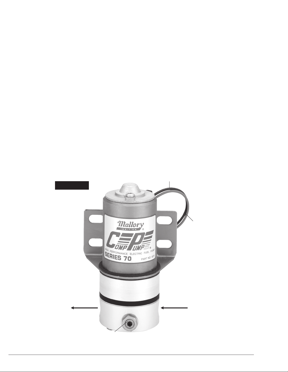
FIGURE 1
3/8” NPT
OUTLET
(TOP)
BLACK WIRE (–)
RED WIRE (+)
3/8” NPT
INLET
BYPASS ADJUSTMENT
(BYPASS PLUG AND
JAM NUT)
2
(BOTTOM)
Page 3

IGNITION SWITCH
TO ACCESSORIES
TO COIL (+)
FROM
VEHICLE
BATTERY
FUSE (5 AMP)
BLACK
RED
FUEL
PUMP
GROUND
IGNITION SWITCH
TO ACCESSORIES
TO COIL (+)
FROM
VEHICLE
BATTERY
GROUND
VEHICLE
BATTERY
OIL PRESSURE SWITCH
NORMALLY
OPEN
NORMALLY
CLOSED
COMMON
FUSE (5 AMP)
BLACK
RED
FUEL
PUMP
STARTER
GROUND
12 VOLT OUTPUT TERMINAL
ON STARTER THAT HAS 12
VOLT ONLY WHILE STARTER
IS CRANKING
CARB
FUEL
FILTER
REGULATOR
(optional)
FUEL
PUMP
FUEL
FILTER
FUEL
TANK
COMP
FILTER
®
PART NO.
3140
FIGURE 2
FIGURE 3
FIGURE 4
3
Page 4

WIDE GAP FACES TO THE REAR
(BRACKET SIDE)
SMALLGAP FACES TO FRONT
(BYPASS ADJUSTER SIDE)
FIGURE 5
MALLORY IS A TRADEMARK OF PRESTOLITE PERFORMANCE
CLEVELAND, OHIO
216.688.8300 FAX 216.688.8306
www.malloryperformance.com
1. Jam Nut
2. Bypass Plug
3. Bypass Spring
4. Screw, Fuel Chamber (2)
5. Bypass Plunger
6. Pad, Bypass Plunger
7. Screen, Flame Arrestor
8. Fuel Chamber
9. Gasket, Fuel Chamber
10. Port Plate
11. Gerotor
12. O-Ring
13. Gerotor Housing
14. Motor
FORM #1394
REV. D (01/12)
MADE IN USA
PRINTED IN USA
 Loading...