

GB
Miter saw stand
Instruction manual
F
Support de scie à onglet
Manuel d’instructions
D
Gestell für Gehrungssäge
Betriebsanleitung
I Supporto per sega circolare Istruzioni per l’uso
NL
Verstekzaagtafel
Gebruiksaanwijzing
E
Soporte para sierra ingletadora
Manual de instrucciones
WST01
2
12
34
56
78
2
5
1
9
3
4
9
7
8
5
1
6
10
10
6
6
11
11
12
13
14
1
2
2
3
3
15
3
2
1
A
19
18
16
17
19
B
20
20
21

3
ENGLISH
Models:
LS1013, LS1016, LS1017, LS1018, LS1214, LS1212, LS1216, LS1030N, LS1040, LH1040, LS1220, LS1221, LS0714,
MT230, M243, MLS100, BLS713
Inclusive of models followed by F, L and FL, if any.
Preparation
Note: Check contents of package for the following components. Please inform Makita service center of any part missing in
the package immediately.
• Miter saw stand assembly (1 unit)
• Hex wrench 6 (1 pc.)
• Wrench 13 (1pc.)
• Hex socket bolt M8 x 16 (4 pcs.)
• Hex socket bolt M8 x 30 (4 pcs.)
• Hex bolt M8 x 50 (4 pcs.)
• Washer 8 (4 pcs.)
• Wheel 300 (2 pcs.)
• Washer 8 (2 pcs.)
• Foot arm (1 pc.)
• Handle (1 pc.)
• Adjusting bolt (2 pcs.)
• Clamping nut M12 (2 pcs.)
Explanation of general view
Symbols
............. Read instruction manual.
............. Maximum allowable loading
CAUTION:
• Read and thoroughly understand this manual and the
instruction manual of the tool you use before
performing the following.
• Before installing a tool on this stand, always switch off
and unplug the tool.
• The stand should be bolted in a stable and level
surface using the bolts provided on two of four feet.
• Use only with Makita model indicated in the instruction
manual.
• Use only the handle to avoid pinched fingers when
raising or folding the stand.
• Before operating the tool, secure it to stand using bolts.
• Do not use the stand on uneven or unstable surface.
• Do not climb, sit or stand on the stand.
• When setting up the miter saw stand in the upright
position or folding it, be sure to securely keep pressing
the pipe of miter saw stand with your foot until it locks.
• When storing miter saw stand, never lean it against the
wall or the like lengthwise or sideways.
• Never pull the locking lever without holding the handle.
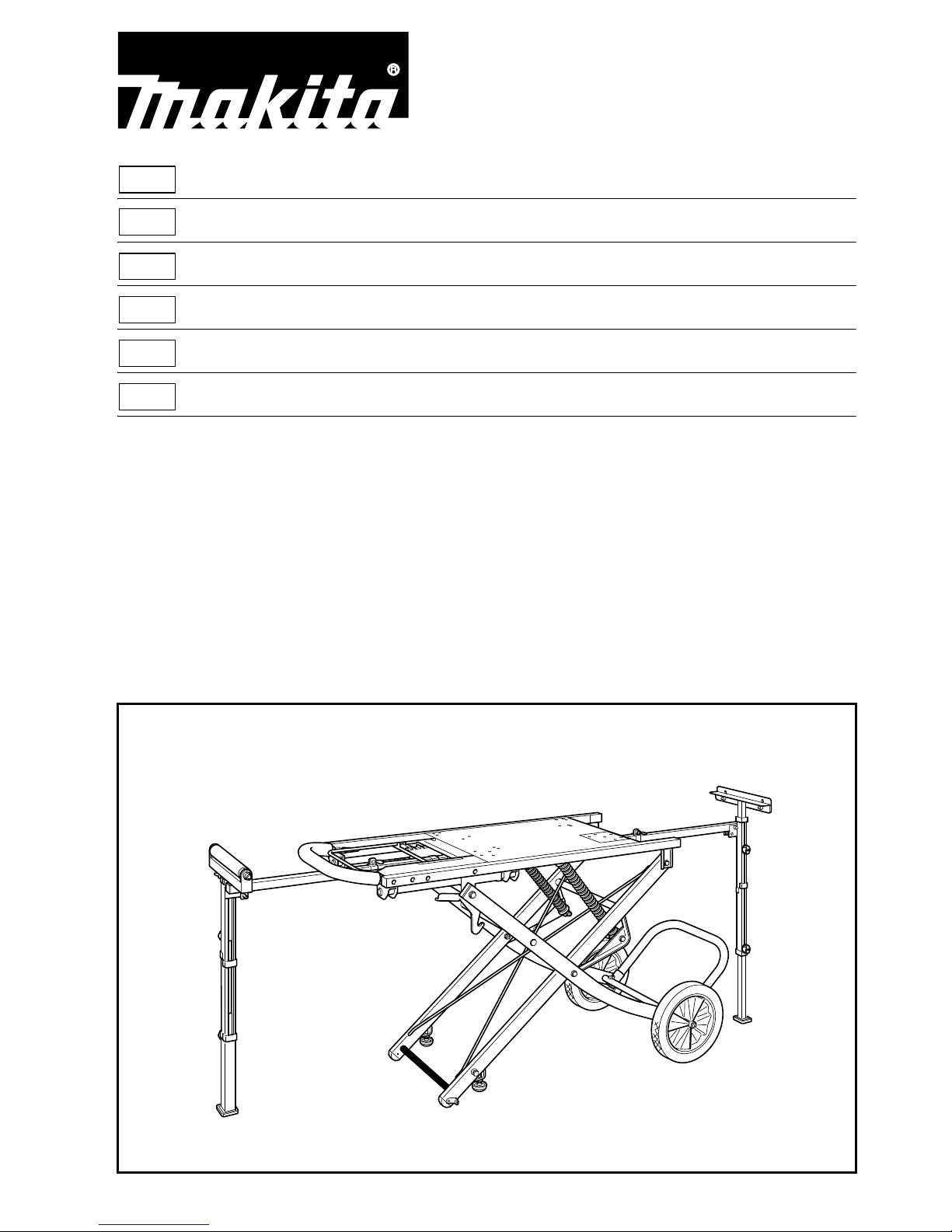
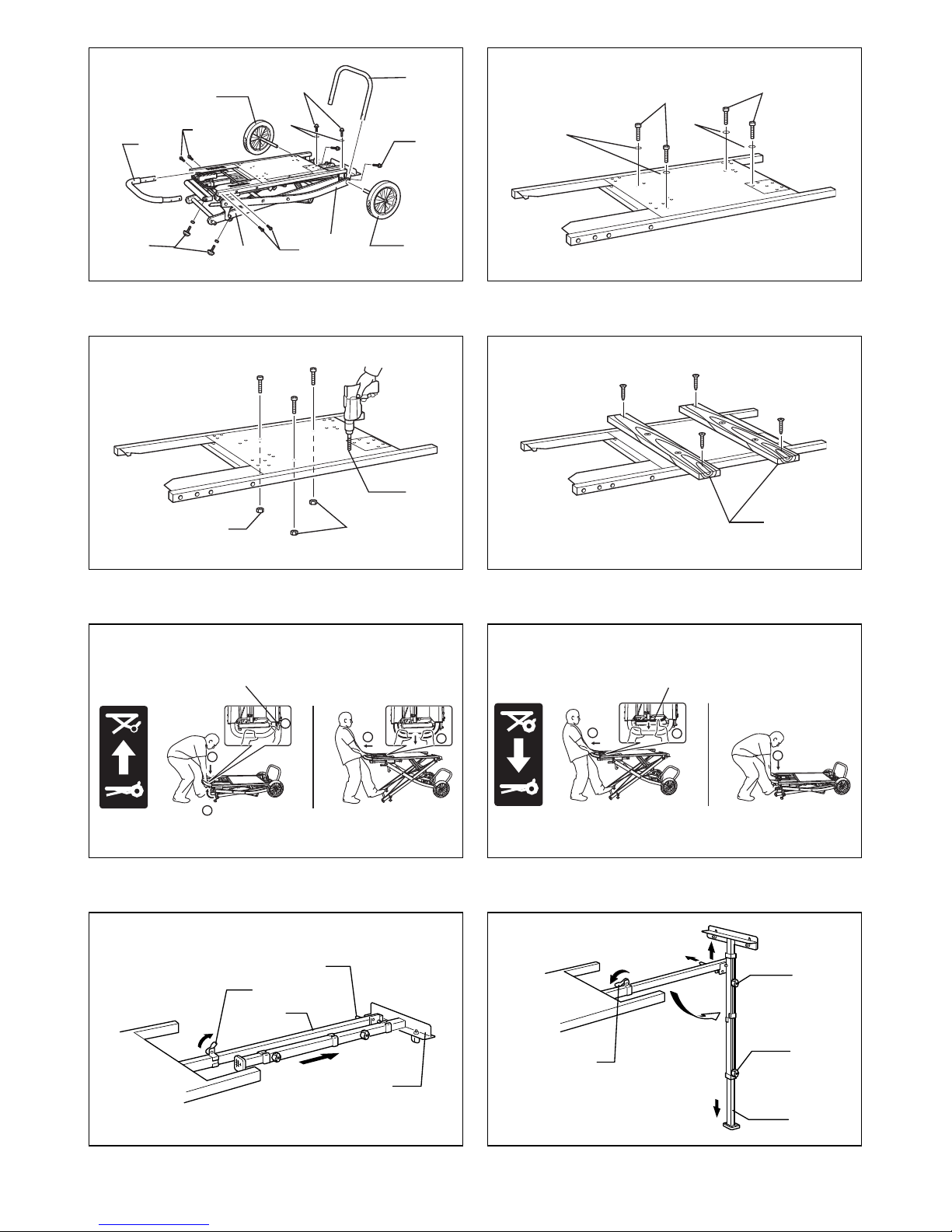
Assembling miter saw stand (Fig. 1)
Assemble parts for miter saw stand as disassembled parts
are packed in the carton box.
(1) Adjusting bolt
Place the stand assembly upright and insert adjusting
bolts (2 pcs.) from the below and secure these bolts by
tightening nuts.
To adjust, turn the adjusting bolts until it reaches floor
so that the miter saw stand can be kept stable.
(2) Wheel 300 (2 pcs.)
Insert the wheels onto the leg B of miter saw stand on
both sides and secure the wheels by tightening hex
socket bolt M8 x 16 (2 pcs.) with washer 8 (2 pcs.)
from upper side.
(3) Foot arm
Insert the foot arm onto the port of the leg B from
upper side and secure it by tightening hex socket bolt
M8 x 16 (2 pcs.) from backside.
(4) Handle
Insert the handle onto the miter saw stand from the
cover side and secure it by tightening hex socket bolt
M8 x 30 (4 pcs.) from the ratchet cover side.
Installing a miter saw models specified
below on the miter saw stand: (Fig. 2)
Place a miter saw so that the hole in the miter saw base
overlaps a hole in the label on the miter saw stand table
according to applicable models. These holes come with
nut M8 (4 pcs). Secure the miter saw stand with Hex bolt
M8 x 50 (4 pcs.)
LS1013, LS1016, LS1017, LS1018, LS1214, LS1212,
LS1216, LS1030N, LS1040, LH1040, LS1220, LS1221,
LS0714, MT230, M243, MLS100
Installing a miter saw models other than
above models on the miter saw stand with
pitches between the holes in miter saw
1. Wheel 300
2. Foot arm
3. Handle
4. Adjusting bolt
5. Hex socket bolt M8 x 16
6. Flat washer 8
7. Leg B
8. Leg A
9. Hex socket bolt M8 x 30
10. Hex bolt M8 x 50
11. Hex nut M8
12. Hole
13. Wood Plate
14. Locking lever
15. Shift lever
16. Pin 10-60
17. Stopper
18. Extension arm
19. Lever 40
20. Clamping screw M8 x 20
21. Leg pipe 28
(220 lbs.)
100Kg
MAX.

4
base within width or length of miter saw
stand table. (Fig. 3)
Drill the it to obtain appropriate holes and using these
holes.
Installing a miter saw models other than
above models on the miter saw stand with
pitches between holes in miter saw base
equal to or beyond the width or length of
miter saw stand table. (Fig. 4)
Prepare two wood plates or the like, drill it to obtain
appropriate holes and using these holes secure these
plates on the miter saw stand. Then drill the plates for
holes to fit the holes in a miter saw base and secure the
miter saw firmly using bolts and nuts.
How to use miter saw stand
Setting up: (Fig. 5)
1. Grip the handle and place your foot on the pipe of the
leg A of miter saw stand.
2. Release the locking lever with left hand while pressing
down the handle.
3. Grab the handle with both hands and pull it backwards
through your weight.
4. Raise the handle up to your desired one of height
levels 1 to 5 according to your work by aligning the
index bar with the height positions shown on the label.
5. Turn the adjusting bolt so that the miter saw stand can
be stable.
Folding: (Fig. 6)
1. Place your foot on the pipe of the leg A of miter saw
stand.
2. Grab the handle with both hands and pull it backwards
through your weight.
3. Hold the handle firmly and pull the shift lever with a
finger while holding it.
4. Lower the handle up to your desired one of height
levels 1 to 5 according to your work by aligning the
index bar with the height positions shown on the label.
5. Lowering further after going past the height level 1
lock the handle by itself.
6. The miter saw stand can be moved with wheels as
shown in the figure.
Setting up the extension arms (for the repetitive
length stopper and the roller): (Fig. 7 & 8)
1. Move the lever 40 toward the side of miter saw
placement in the A direction of arrow, pull out the
extension arm until its end reaches the repetitive
length or the support length and lock it by moving the
lever 40 in the B direction of arrow.
2. Pull out the pin 10-60, pivot the leg so that it is upright.
Make sure that the pin top end is locked in the hole in
the leg pipe.
3. Loosen the clamping screw M8 x 20 on the leg
counterclockwise, pull out the leg pipe until it reaches
the floor and tighten the clamping screw M8 x 20 back
counterclockwise the leg pipe.
4. Loosen the clamping screw M8 x 20 on the side of the
stopper for the repetitive length or the roller
counterclockwise, raise or lower the stopper (or the
roller) until the top edge of the stopper (or the top of
roller) reaches the same level as the top surface of the
miter saw table. Retighten the clamping screw M8 x
20 clockwise to lock the stopper (or roller).
Storing the extension arm for both the stopper to gain
repetitive cuts and the roller: (Fig. 7 & 8)
1. Loosen the lever 40, push back the leg pipe 28 and
retighten the lever.
2. Loosen the lever 40 nearer to the stopper (or the
roller), press down the stopper (or the roller) and
retighten the lever.
3. Pull out the pin 10-60, pivot the leg until it reaches to
the horizontal position.
4. Loosen the lever 40, push back the extension arm as
far as it will go and retighten the lever firmly to lock the
extension bar.

5
FRANÇAIS
Modèles :
LS1013, LS1016, LS1017, LS1018, LS1214, LS1212, LS1216, LS1030N, LS1040, LH1040, LS1220, LS1221, LS0714,
MT230, M243, MLS100, BLS713
Comprend les modèles suivis de F, L et FL, s’il y a.
Préparation
Remarque : Vérifiez que l’emballage contient les composants suivants. Veuillez informer immédiatement le centre de
réparation de Makita si une pièce manque dans l’emballage.
• Montage du support de scie à onglet (1 unité)
• Clé à mollette 6 (1 pièce)
• Clé 13 (1 pièce)
• Boulon de clé à mollette M8 x 16 (4 pièces)
• Boulon de clé à mollette M8 x 30 (4 pièces)
• Boulon à tête hexagonale M8 x 50 (4 pièces)
• Rondelle 8 (4 pièces)
• Roue 300 (2 pièces)
• Rondelle 8 (2 pièces)
• Bras de pied (1 pièce)
• Poignée (1 pièce)
• Boulon de réglage (2 pièces)
• Ecrou de serrage M12 (2 pièces)
Descriptif
Symboles
............. Reportez-vous au manuel d’instructions.
............. Charge maximale permissible
ATTENTION :
• Avant de poursuivre, veuillez d’abord lire et bien
comprendre ce manuel et le mode d’emploi de l’outil
que vous utiliserez.
• Avant d’installer l’outil sur ce support, vous devez
couper le contact et débrancher l’outil.
• Le support doit être boulonné sur une surface stable et
plane, à laide des boulons prévus sur deux des quatre
pieds.
• Utilisez uniquement le modèle Makita indiqué dans le
mode demploi.
• Utilisez uniquement la poignée pour éviter de vous
pincer les doigts en déployant le support ou en le
repliant.
• Avant d’utiliser l’outil, fixez-le au support à l’aide des
boulons.
• Ne pas utiliser le support sur une surface inégale ou
instable.
• Ne pas monter sur le support, ni s’asseoir ou s’appuyer
dessus.
• Quand vous installez le support de la scie à onglet en
position redressée ou pliée, veillez à maintenir une
pression sur le tube du support de la scie à onglet avec
votre pied jusqu’à ce qu’il se verrouille.
• Lorsque vous entreposez le support de la scie à onglet,
ne l’adossez jamais contre un mur ou généralement
dans la longueur ou la largeur.
• Ne jamais tirer sur le levier de verrouillage sans tenir la
poignée.
Montage du support de scie à onglet
(Fig. 1)
Assemblez les pièces emballées dans la boîte en carton
pour le support de scie à onglet.
(1) Boulon de réglage
Placez l’ensemble du support en position redressée et
insérez les boulons de réglage (2 pièces) en
commençant par le bas et sécurisez ces boulons à
l’aide d’écrous de serrage.
Pour l’ajustage, tournez les boulons de réglage
jusqu’à atteindre le sol pour que le support de scie à
onglet puisse rester stable.
(2) Roue 300 (2 pièces)
Insérez les roues sur le pied B du support de scie à
onglet des deux côtés et sécurisez les roues en
serrant le boulon de clé à mollette M8 x 16 (2 pièces)
avec la rondelle 8 (2 pièces) depuis le sommet.
(3) Bras de pied
Insérez le bras de pied sur le port du pied B depuis le
sommet et sécurisez-le en serrant le boulon de clé à
mollette M8 x 16 (2 pièces) depuis l’arrière.
(4) Poignée
Insérez la poignée sur le support de scie à onglet
depuis le côté du couvercle et sécurisez-la en serrant
le boulon de clé à mollette M8 x 30 (4 pièces) depuis
le côté du couvercle de rochet.
1. Roue 300
2. Bras de pied
3. Poignée
4. Boulon de réglage
5. Boulon de clé à mollette M8 x 16
6. Rondelle plate 8
7. Pied B
8. Pied A
9. Boulon de clé à mollette M8 x 30
10. Boulon à tête hexagonale M8 x 50
11. Écrou hexagonal M8
12. Orifice
13. Plaque de bois
14. Levier de verrouillage
15. Levier de manœuvre
16. Broche 10-60
17. Butée
18. Bras d’extension
19. Levier 40
20. Vis de serrage M8 x 20
21. Tube de pied 28
(220 lbs.)
100Kg
MAX.
 Loading...