

Page 1
T
ECHNICAL INFORMATION
Model No.
Description
UH200D (HU01*)
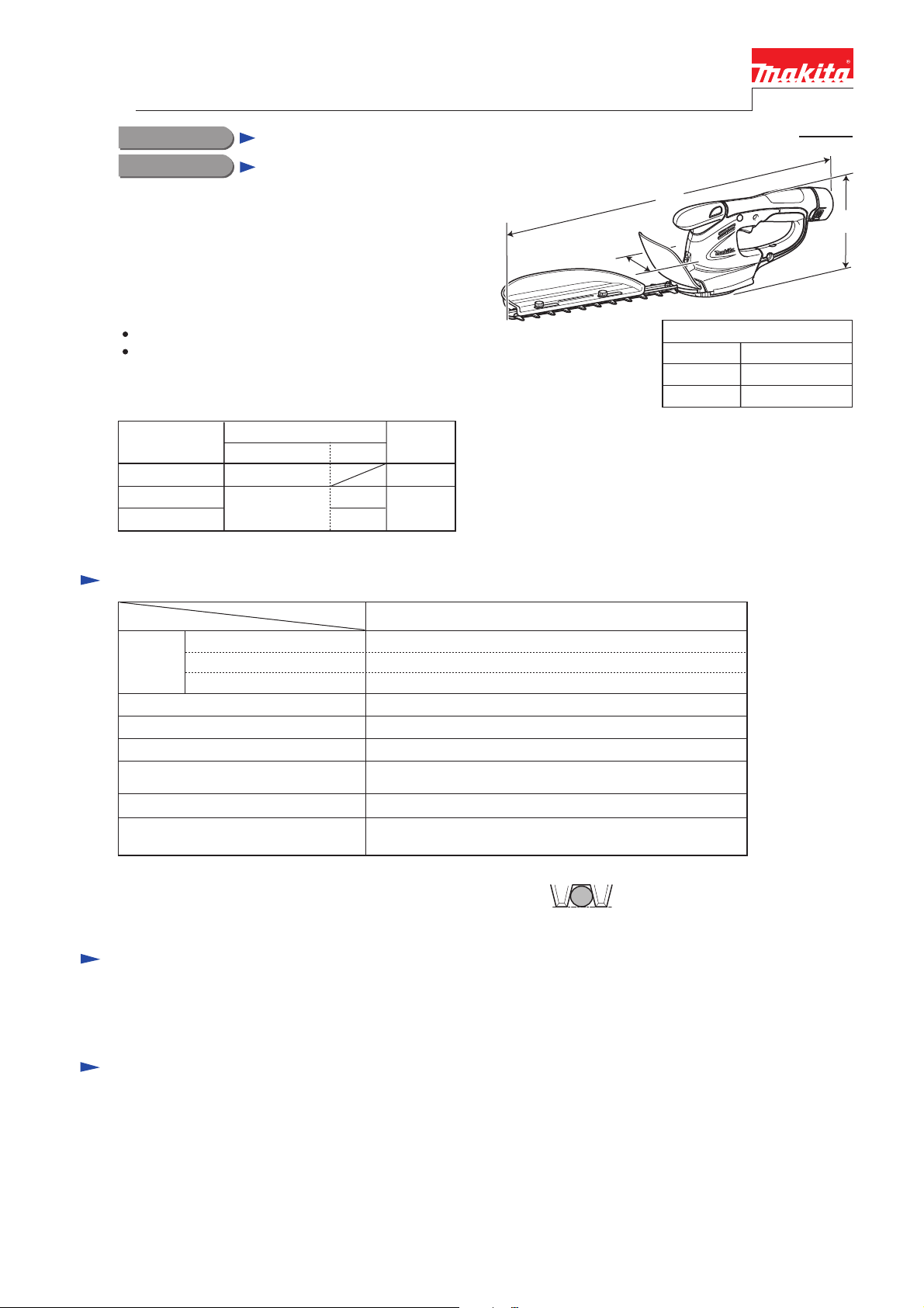
Cordless Hedge Trimmer 200mm (7-7/8)
*1: Model number for North and Central American countries
CONCEPT AND MAIN APPLICATIONS
Model UH200D is 200mm Cordless hedge trimmer
powered by 10.8V/ 1.3Ah Li-ion battery BL1013.
Its main features are:
Lightweight and compact design for easy handling
Optional Grass shear blade kit can convert this model
into Model UM164D Cordless grass shear.
This product is available in the following variations.
Model No.
UH200DZ No No
UH200DW
UH200DWE 2
(Li-ion 1.3Ah)
Battery
type quantity
BL1013
1
Charger
DC10WA
L
W
Dimensions*1: mm (")
Length (L) 460 (18-1/8)
Width (W)
Height (H)
*1 without chip receiver
PRODUCT
P 1/ 8
H
120 (4-3/4)
130 (5-1/8)
All models also include the accessories listed in "Standard equipment".
Specification
Specification
Voltage: V
Battery
No load speed: min-1=spm*2
Blade length: mm (") 200 (7-7/8)
Tooth spacing: mm (") 26 (1)
Maximum branch
diameter*3: mm (")
Overload protection
Weight according to
EPTA-Procedure 01/2003 *4: kg (lbs)
*2 spm= stroke per minute
*3: Indicates maximum diameter of the branch that can be received
between adjacent two blade teeth. (See the figure on right.)
*4 with hedge trimmer blade, chip receiver
Capacity: Ah
Cell
Model
UH200D
10.8
1.3
Li-ion
1,250
8 (5/16)
Yes
1.2 (2.7)
Standard equipment
Chip receiver ..................................................... 1
Blade cover ........................................................ 1
Note: The standard equipment for the tool shown above may differ by country.
Optional accessories
Battery BL1013
Charger DC10WA
Grass shear blade kit*5 (with a bottle of lubricant grease)
Hedge trimmer blade kit*6 (with a bottle of lubricant grease)
Extension handle kit*5
Chip receiver set*6
Accessory kit for use as a hedge trimmer*6 (including Blade cover, etc.)
Accessory kit for use as a grass shear*5 (including Base frame, etc.)
*5 for use as a grass shear
*6 for use as a hedge trimmer
Page 2
P 2/ 8
Repair
CAUTION: Repair the machine in accordance with “Instruction manual” or “Safety instructions”.
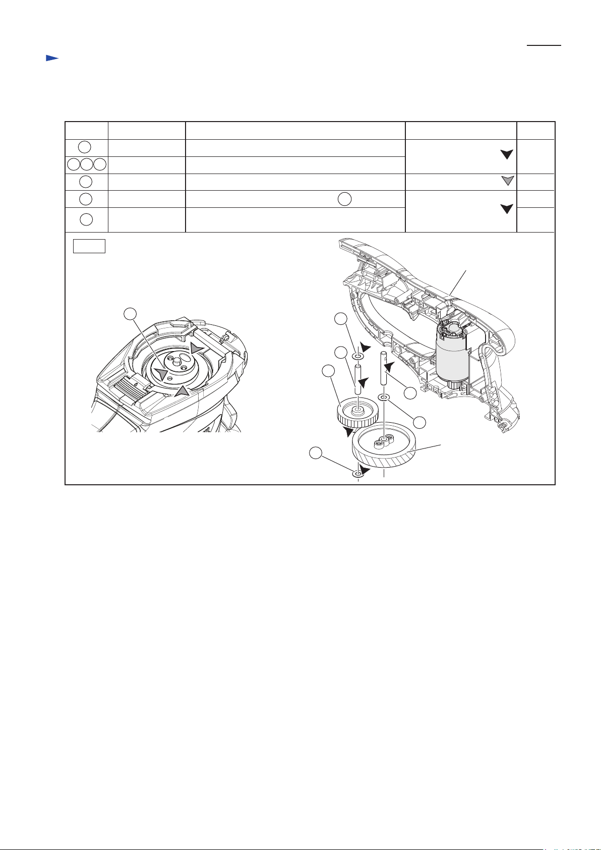
[1] LUBRICATIONS
Fig. 1
Item No.
Apply the following lubricant to protect parts and product from unusual abrasion.
Description
Crank
Helical gear 47
Housing complete (L)
Gear 12-31
Gear teeth with which Helical gear 47 and DC motor
gear engage
Drum portions where Blade contact
17 Pin 6 (with notch) Drum portion for smooth rotation of Helical gear 47
18 24 26 Washer 6 Whole portion
a little
2g
Lubricant
Amount
Portion to lubricate
18
24
17
26
21
21
2323Pin 6
1.5g
a little
Makita grease N No.2
Molybdenum disulfide
Drum portion for smooth rotation of 25 Gear 12-31
25
25
Makita grease N No.2
Page 3
Shear blade assembly
P 3/ 8
Fig. 2
Repair
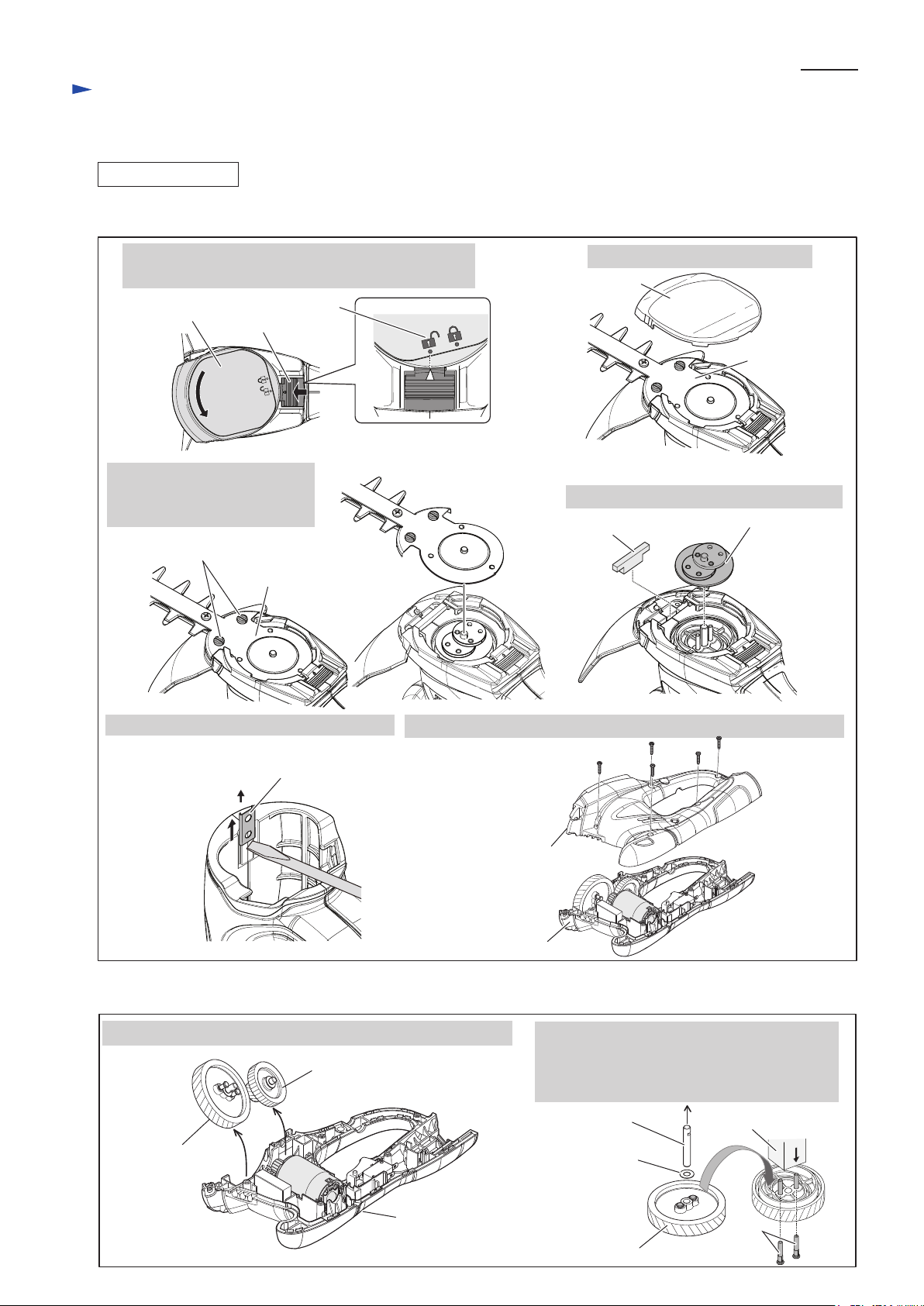
[2] DISASSEMBLY/ASSEMBLY
[2]-1. Gear 12-31, Helical gear 47
DISASSEMBLING
(1) Remove Blade, Crank and Housing set (R) as illustrated in Fig. 2.
3. Loosen two M4 Countersunk
head screws, and then remove
Shear blade assembly.
Under cover
complete
4. Remove Crank complete and Dust guard.
Dust guard
2. Remove Under cover complete.
Shear blade
assembly
M4 Countersunk head screw
Crank complete
Lock lever
Under cover
complete
1. With pressing Lock lever, turn Under cover complete
to the unlocked position as drawn below.
Unlocked position
Set plate
5. Remove Set plate with slotted screwdriver. 6. Separate Housing set (R) by unscrewing five 3x16 Tapping screws.
Fig. 3
Helical gear 47
1. Remove Helical gear 47 and Gear 12-31 from Housing set (L). 2. After removing Washer 6 and Pin 6 which
functions as a shaft for the Helical gear 47,
remove 2 pcs. of Pin 4 by pressing with
Arbor press. Helical gear 47 can be replaced.
Gear 12-31
Pin 6 (with a notch)
Washer 6
Arbor press
(2) After removing Housing set (R), Helical gear 47 and Gear 12-31 can be removed. (Fig. 3)
Helical gear 47
Housing set (L)
Pin 4
(2pcs.)
Housing set (R)
Housing set (L)
3x16 Tapping screw
(5pcs.)
Page 4

P 4/ 8
Repair
[2] DISASSEMBLY/ASSEMBLY
[2]-1. Gear 12-31, Helical gear 47
Fig. 4
Fig. 5
Fig. 6
ASSEMBLING
(1) Assemble Helical gear 47, Gear 12-31. (Figs. 4, 5)
And mount them to Housing set (L). (Fig. 6)
Crank side of Helical gear 47
1. Face the crank side of
Helical gear 47 to the bottom.
2. Assemble two Pins 4 to
Helical gear 47 by pressing
with Arbor press.
3. Facing the notch side of Pin 6
to top, pass it through Washer 6
into Helical gear 47.
5. Assemble Helical gear 47 with
fitting the notch of Pin 6 on the Rib
of Housing set (L).
Notch on Pin 6
Helical gear 47
DC Motor
Rib
Washer 6
Housing set (L)
Notch
Pin 6
Pin 4
(2pcs.)
Fig. 7
(2) Assemble Protector to housing set. (Center right in Fig. 2)
(3) Mount Crank complete. (Fig. 7)
(4) Mount Shear blade assembly and Under cover. See Figs. 10, 11 in “[3]-3. Shear Blade Assembly”.
Dust guard
6. Mount Crank complete and Dust guard.
for UH200D
for UM164D
Crank complete
<Note>
Crank complete has an interchangeability between UM164D
cordless grass shear and UH200D cordless hedge trimmer by
reversing as illustrated below.
In case of UH200D, engage this side with Shear blade assembly.
4. Pass Pin 6 through Gear 12-31
and two Washers 6 as drawn below,
then set them in place in Housing L.
Pin 6
Washer 6
Washer 6
Gear 12-31
Page 5

P 5/ 8
Repair
[2] DISASSEMBLY/ASSEMBLY
[2]-2. DC motor
Fig. 8
Fig. 9
DISASSEMBLING
(1) Disassemble DC motor. (Fig. 8)
Set plate
1. Remove Set plate and separate Housing set (R)
by unscrewing five 3x16 Tapping screws.
2. DC Motor can be removed
from Housing set (L).
3x16 Tapping screw
(5pcs.)
Housing set (R)
DC motor
Housing set (L)
ASSEMBLING
Set DC motor to Housing set (L). (Fig. 9)
Assemble DC motor with fitting its notch
on the convex of Housing set (L).
DC motor
Page 6

P 6/ 8
Repair
[2] DISASSEMBLY/ASSEMBLY
[2]-3. Shear blade assembly
1. Adjust Crank complete to
the position as drawn below.
Joint of Housing set (L)
and Housing set (R)
2. Align the Holes of Shear blade A and B
to the Hole of Guide plate in order to set
M4 Pan head screw as a positioning pin.
M4 Pan head
screw
Shear blade B
Guide plate
Shear blade A
Crank complete
M4 Countersunk
head screw
Shear blade
assembly
4. Tighten M4 Countersunk head screws.
DISASSEMBLING
(1) Pull the rear portion of Base frame toward rear side designated with arrow. (Top left in Fig. 2)
(2) With pressing Lock lever, turn under cover complete to the unlocked position. (Top right in Fig. 2)
(3) Disassemble Under cover, and then remove Shear blade assembly. (Center left in Fig. 2)
Fig. 10
ASSEMBLING
(1) Mount Shear blade assembly. (Fig. 10)
3. Mount Shear blade assembly
with fitting the loops of Shear
blades A and B into Crank
complete
Fig. 11
(2) Mount Under cover complete. (Fig. 11)
5. Put Under cover complete on the bottom of
Housing set as drawn below.
6. With pressing Lock lever, turn Under cover complete
toward the locking position as drawn below.
Lock lever
Under cover
complete
Unlocked position
Locking position
Page 7

Circuit diagram
P 7/ 8
Fig. D-1
White
Color index of lead wires' sheath
Black
Red
Blue
LED
(Warning lamp for battery)
DC Motor
Controller
Line filter
Switch
Terminal
Line filter is not used
for some countries.
Wiring diagram
Fig. D-2
1. Find Terminal marked with Red dot marking.
2. Now connect the Lead wire (white) receptacle to
the Terminal with Red dot marking and the Lead
wire (blue) receptacle to the another Terminal.
Lead wire
(blue)
Red dot marking
Wire connecting portion of
Receptacles
Lead wire
(white)
Housing set (L)
3. DC motor can be mounted with facing
the wire connecting portions of Receptacles
to Housing set (L) side.
Page 8

P 8/ 8
Fig. D-6
Fig. D-5
Switch
Fix Controller´s Lead wires
(red, black) in this Lead
wire holder.
Connect Receptacles to the Switch with facing the wire
connecting portion to the Housing set (L) side in order
to put the Lead wires on the Housing set (L).
Connect Receptacles to the Terminal with facing
the wire connecting portion to Housing set (L) side.
Adhesive
Pass the Lead wires of
LED circuit between
the Ribs.
LED circuit
In case Line filter has to
be used, put Line filter
into the space designated
with gray color.
Controller
Controller
Housing set
(L) side
Housing set
(L) side
DC motor
Switch
Terminal
Fix all of the Lead wires
of Controller in this
Lead wire holder.
from Plus pole
of Terminal
from Controller
Terminal
Wiring diagram (cont.)
Fig. D-3 Fig. D-4
Controller
Controller has to be put into Housing set (L).
Note: Bring the Lead wire (blue) connecting portion to the bottom
side (Helical gear 47 side) and the wires connecting portions
to the front side (protector side).
Line filter
Wind Controller´s Lead wires (blue, white)
one time around Line filter.
To Plus pole of DC Motor
To Minus pole
of DC Motor
Lead wire (blue)
Front side
(Protector side)
Bottom side (Helical gear 47 side)
Housing set (L)
DC Motor
 Loading...