Makita TD111DY1J User Manual
...
Makita User Manual
Specifications and Main Features
Frequently Asked Questions
Page 1
Page 2
Page 3
Page 4
Page 5
Page 6
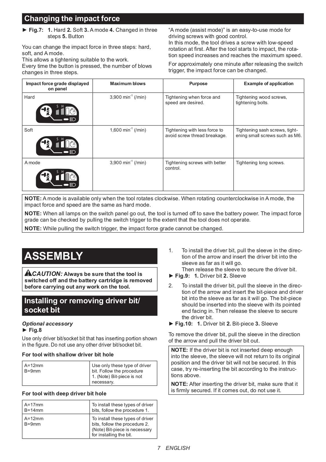
Page 7
Page 8
Page 9
Page 10
Page 11
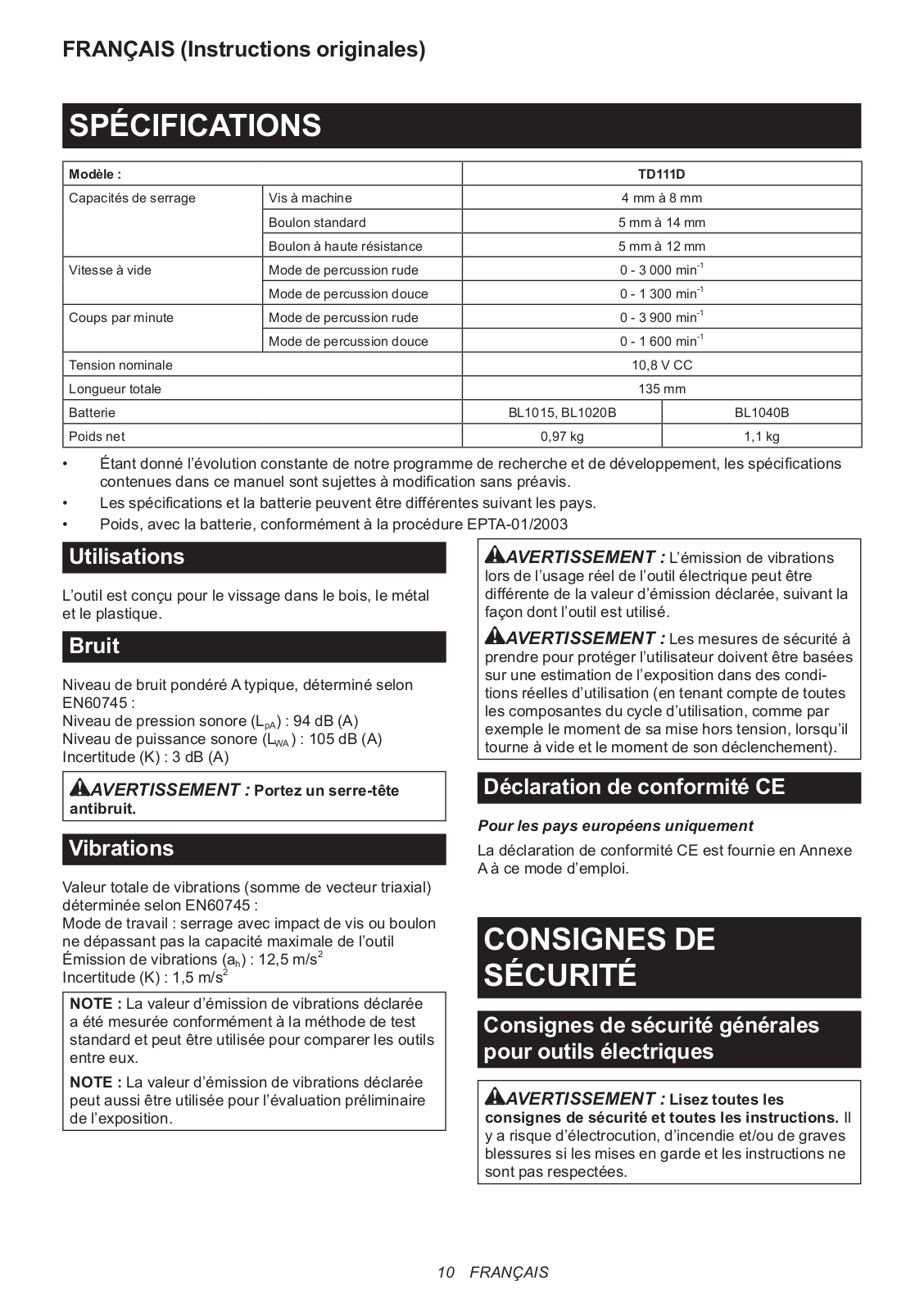
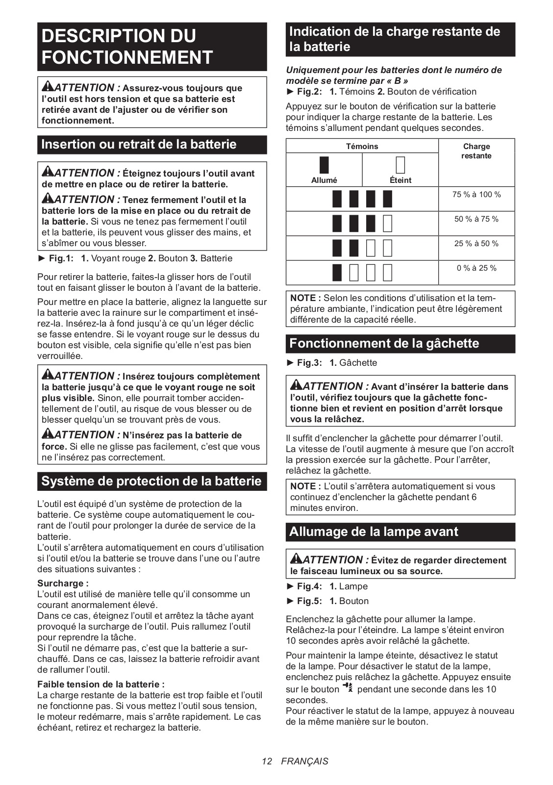
Page 12
Page 13
Page 14
Page 15
Page 16
Page 17
Page 18
Page 19
Page 20
Page 21
Page 22
Page 23
 Loading...