

Page 1

EN
Cordless Impact Driver
INSTRUCTION MANUAL 4
PL
HU
SK
CS
UK
RO
DE
ůkuЦuХКtШrШавăАkrtКkă
Udarowy
Akkumulátoros
ütvecsavarbehajtó
Akumulátorový rázový
uťКСШЯКč
Akumulátorový rázový
utahovák
ăă
MКşТЧăНОăîЧşuruЛКtăМuă
impact cu acumulator
Akku-Schlagschrauber
TD110D
IІSTRUKűJůăЇŰSŁUżI 9
HASZNÁLATI KÉZIKÖNYV 15
NÁVOD NA OBSLUHU 21
NÁVOD K OBSLUZE 26
ăă
MůІUůLăDźăIІSTRUűIUІI 37
ŰźTRIźŰSůІLźITUІż 43
31
Page 2
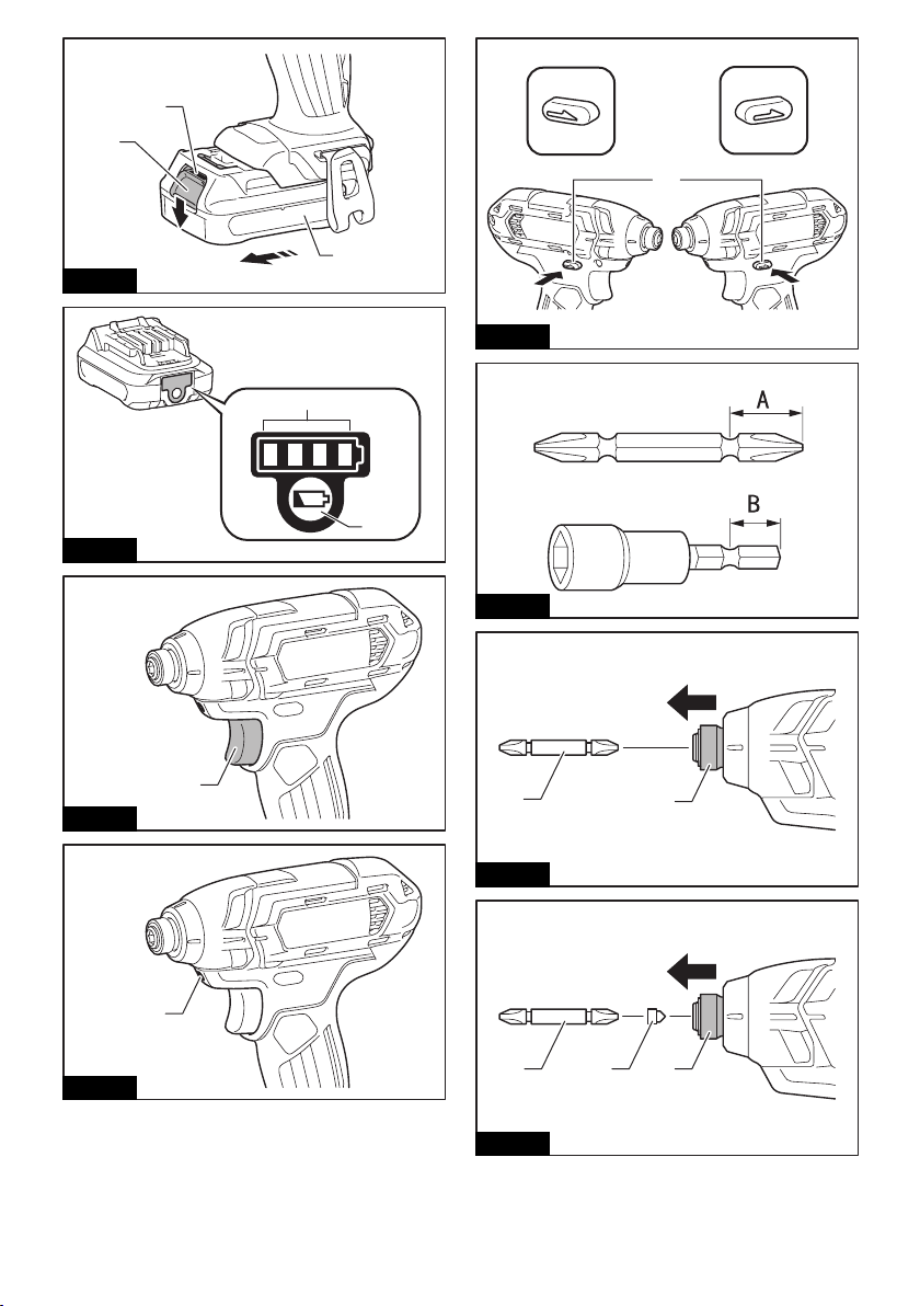
Fig.1
AB
Fig.2
1
2
1
3
Fig.5
1
2
Fig.6
1
Fig.3
1
Fig.7
1
Fig.4
Fig.8
2
2
312
Page 3
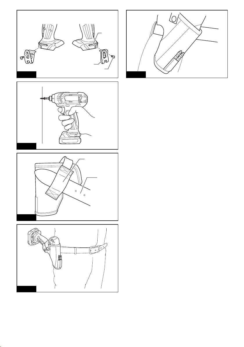
Fig.9
Fig.10
1
2
3
Fig.13
1
2
Fig.11
Fig.12
3
Page 4
źІżLISHăĚЇrТРТЧКХăТЧstruМtТШЧsě
SPECIFICATIONS
Model: TD110D
Fastening capacities Machine screw 4 mm - 8 mm
Standard bolt 5 mm - 12 mm
High tensile bolt 5 mm - 10 mm
No load speed 0 - 2,600 min
Impacts per minute 0 - 3,500 min
Overall length 153 mm
Rated voltage D.C. 10.8 V
Battery cartridge BL1015, BL1020B BL1040B
Net weight 1.0 kg 1.2 kg
•ă DuОătШăШurăМШЧtТЧuТЧРăЩrШРrКЦăШПărОsОКrМСăКЧНăНОЯОХШЩЦОЧt,ătСОăsЩОМТiМКtТШЧsăСОrОТЧăКrОăsuЛУОМtătШăМСКЧРОă
without notice.
•ă SЩОМТiМКtТШЧsăКЧНăЛКttОrвăМКrtrТНРОăЦКвăНТППОrăПrШЦăМШuЧtrвătШăМШuЧtrв.
• Weight, with battery cartridge, according to EPTA-Procedure 01/2003
IЧtОЧНОНăusО
The tool is intended for screw driving in wood, metal
and plastic.
Noise
The typical A-weighted noise level determined according to EN60745:
Sound pressure level (LpA) : 94 dB(A)
Sound power level (LWA) : 105 dB (A)
Uncertainty (K) : 3 dB(A)
АůRІIІżŚ АОКrăОКrăprШtОМtТШЧ.
VТЛrКtТШЧ
The vibration total value (tri-axial vector sum) determined according to EN60745:
Work mode: impact tightening of fasteners of the maximum capacity of the tool
Vibration emission (ah) : 8.0 m/s
Uncertainty (K) : 1.5 m/s
NOTE: The declared vibration emission value has
been measured in accordance with the standard test
method and may be used for comparing one tool with
another.
NOTE: The declared vibration emission value
may also be used in a preliminary assessment of
exposure.
2
2
АůRІIІżŚ The vibration emission during actual
use of the power tool can differ from the declared
emission value depending on the ways in which the
tool is used.
АůRІIІżŚ Be sure to identify safety measures to
protect the operator that are based on an estimation
of exposure in the actual conditions of use (taking
account of all parts of the operating cycle such as
the times when the tool is switched off and when it is
running idle in addition to the trigger time).
źűăDОМХКrКtТШЧăШПăűШЧПШrЦТtв
For European countries only
Makita declares that the following Machine(s):
Designation of Machine: Cordless Impact Driver
Model No./ Type: TD110D
Conforms to the following European Directives:
2006/42/EC
They are manufactured in accordance with the following
standard or standardized documents: EN60745
TСОătОМСЧТМКХăiХОăТЧăКММШrНКЧМОăаТtСă2ŃŃ6/42/ECăТsă
available from:
Makita, Jan-Baptist Vinkstraat 2, 3070, Belgium
24.2.2015
Yasushi Fukaya
Director
Makita, Jan-Baptist Vinkstraat 2, 3070, Belgium
żОЧОrКХăpШаОrătШШХăsКПОtвăаКrЧТЧРs
-1
-1
4 ENGLISH
АůRІIІżŚ RОКНăКХХăsКПОtвăаКrЧТЧРsăКЧНăКХХă
ТЧstruМtТШЧs.ăFailure to follow the warnings and
ТЧstruМtТШЧsăЦКвărОsuХtăТЧăОХОМtrТМăsСШМФ,ăirОăКЧН/Шră
sОrТШusăТЧУurв.
Page 5
SКЯОăКХХăаКrЧТЧРsăКЧНăТЧstruМtТШЧsăПШrăПuturОărОПОrОЧМО.
The term "power tool" in the warnings refers to your
mains-operated (corded) power tool or battery-operated
(cordless) power tool.
űШrНХОssăТЦpКМtăНrТЯОrăsКПОtвă
аКrЧТЧРs
1. HШХНăpШаОrătШШХăЛвăТЧsuХКtОНăРrТppТЧРăsur-
ПКМОsĽăаСОЧăpОrПШrЦТЧРăКЧăШpОrКtТШЧăаСОrОă
tСОăПКstОЧОrăЦКвăМШЧtКМtăСТННОЧăаТrТЧР.
Fasteners contacting a "live" wire may make
exposed metal parts of the power tool "live" and
could give the operator an electric shock.
2. ůХаКвsăЛОăsurОăвШuăСКЯОăКăirЦăПШШtТЧР.
ŰОăsurОăЧШăШЧОăТsăЛОХШаăаСОЧăusТЧРătСОătШШХăТЧă
СТРСăХШМКtТШЧs.
3. HШХНătСОătШШХăirЦХв.
4. Wear ear protectors.
5. DШăЧШtătШuМСătСОăЛТtăШrătСОăаШrkpТОМОăТЦЦОНТ-
КtОХвăКПtОrăШpОrКtТШЧ.ăTСОвăЦКвăЛОăОбtrОЦОХвă
СШtăКЧНăМШuХНăЛurЧăвШurăskТЧ.
6. KООpăСКЧНsăКаКвăПrШЦărШtКtТЧРăpКrts.
SAVE THESE INSTRUCTIONS.
АůRІIІżŚ DЇăІЇTăХОtăМШЦПШrtăШrăПКЦТХТКrТtвă
аТtСăprШНuМtăĚРКТЧОНăПrШЦărОpОКtОНăusОěărОpХКМОă
strТМtăКНСОrОЧМОătШăsКПОtвăruХОsăПШrătСОăsuЛУОМtă
product.
MISUSźăШrăПКТХurОătШăПШХХШаătСОăsКПОtвăruХОsăstКtОНă
ТЧătСТsăТЧstruМtТШЧăЦКЧuКХăЦКвăМКusОăsОrТШusă
pОrsШЧКХăТЧУurв.
IЦpШrtКЧtăsКПОtвăТЧstruМtТШЧsăПШră
battery cartridge
1. ŰОПШrОăusТЧРăЛКttОrвăМКrtrТНРОĽărОКНăКХХăТЧstruМ-
tТШЧsăКЧНăМКutТШЧКrвăЦКrkТЧРsăШЧăĚ1ěăЛКttОrвă
МСКrРОrĽăĚ2ěăЛКttОrвĽăКЧНăĚ3ěăprШНuМtăusТЧРă
battery.
2. DШăЧШtăНТsКssОЦЛХОăЛКttОrвăМКrtrТНРО.
3. IПăШpОrКtТЧРătТЦОăСКsăЛОМШЦОăОбМОssТЯОХвă
sСШrtОrĽăstШpăШpОrКtТЧРăТЦЦОНТКtОХв.ăItăЦКвă
rОsuХtăТЧăКărТskăШПăШЯОrСОКtТЧРĽăpШssТЛХОăЛurЧsă
КЧНăОЯОЧăКЧăОбpХШsТШЧ.
4. IПăОХОМtrШХвtОăРОtsăТЧtШăвШurăОвОsĽărТЧsОătСОЦă
ШutăаТtСăМХОКrăаКtОrăКЧНăsООkăЦОНТМКХăКttОЧtТШЧărТРСtăКаКв.ăItăЦКвărОsuХtăТЧăХШssăШПăвШură
eyesight.
5. DШăЧШtăsСШrtătСОăЛКttОrвăМКrtrТНРОŚ
(1) DШăЧШtătШuМСătСОătОrЦТЧКХsăаТtСăКЧвăМШЧ-
ductive material.
(2) ůЯШТНăstШrТЧРăЛКttОrвăМКrtrТНРОăТЧăКăМШЧ-
tКТЧОrăаТtСăШtСОrăЦОtКХăШЛУОМtsăsuМСăКsă
ЧКТХsĽăМШТЧsĽăОtМ.
(3) DШăЧШtăОбpШsОăЛКttОrвăМКrtrТНРОătШăаКtОră
ШrărКТЧ.
ůăЛКttОrвăsСШrtăМКЧăМКusОăКăХКrРОăМurrОЧtă
lШаĽăШЯОrСОКtТЧРĽăpШssТЛХОăЛurЧsăКЧНăОЯОЧăКă
ЛrОКkНШаЧ.
6. DШăЧШtăstШrОătСОătШШХăКЧНăЛКttОrвăМКrtrТНРОăТЧă
ХШМКtТШЧsăаСОrОătСОătОЦpОrКturОăЦКвărОКМСăШră
ОбМООНăő0ă°űăĚ122ă°Żě.
7. DШăЧШtăТЧМТЧОrКtОătСОăЛКttОrвăМКrtrТНРОăОЯОЧăТПă
ТtăТsăsОЯОrОХвăНКЦКРОНăШrăТsăМШЦpХОtОХвăаШrЧă
Шut.ăTСОăЛКttОrвăМКrtrТНРОăМКЧăОбpХШНОăТЧăКăirО.
8. ŰОăМКrОПuХăЧШtătШăНrШpăШrăstrТkОăЛКttОrв.
9. DШăЧШtăusОăКăНКЦКРОНăЛКttОrв.
10. ŻШХХШаăвШurăХШМКХărОРuХКtТШЧsărОХКtТЧРătШăНТs-
pШsКХăШПăЛКttОrв.
SAVE THESE INSTRUCTIONS.
TТpsăПШrăЦКТЧtКТЧТЧРăЦКбТЦuЦă
ЛКttОrвăХТПО
1. űСКrРОătСОăЛКttОrвăМКrtrТНРОăЛОПШrОăМШЦpХОtОХвă
НТsМСКrРОН.ăůХаКвsăstШpătШШХăШpОrКtТШЧăКЧНă
МСКrРОătСОăЛКttОrвăМКrtrТНРОăаСОЧăвШuăЧШtТМОă
less tool power.
2. ІОЯОrărОМСКrРОăКăПuХХвăМСКrРОНăЛКttОrвăМКrtrТНРО.ăЇЯОrМСКrРТЧРăsСШrtОЧsătСОăЛКttОrвă
sОrЯТМОăХТПО.
3. Charge the battery cartridge with room tem-
pОrКturОăКtă10ă°űăľăŐ0ă°űăĚő0ă°Żăľă10Őă°Żě.ăLОtă
КăСШtăЛКttОrвăМКrtrТНРОăМШШХăНШаЧăЛОПШrОă
МСКrРТЧРăТt.
FUNCTIONAL
DESCRIPTION
CAUTION: Always be sure that the tool is
sаТtМСОНăШППăКЧНătСОăЛКttОrвăМКrtrТНРОăТsărОЦШЯОНă
ЛОПШrОăКНУustТЧРăШrăМСОМkТЧРăПuЧМtТШЧăШЧătСОătШШХ.
IЧstКХХТЧРăШrărОЦШЯТЧРăЛКttОrвă
cartridge
CAUTION: ůХаКвsăsаТtМСăШППătСОătШШХăЛОПШrОă
ТЧstКХХТЧРăШrărОЦШЯТЧРăШПătСОăЛКttОrвăМКrtrТНРО.
CAUTION: HШХНătСОătШШХăКЧНătСОăЛКttОrвăМКr-
trТНРОăirЦХвăаСОЧăТЧstКХХТЧРăШrărОЦШЯТЧРăЛКttОrвă
cartridge. Failure to hold the tool and the battery
МКrtrТНРОăirЦХвăЦКвăМКusОătСОЦătШăsХТЩăШППăвШurăСКЧНsă
and result in damage to the tool and battery cartridge
КЧНăКăЩОrsШЧКХăТЧУurв.
►Fig.1: 1. Red indicator 2. Button 3. Battery
cartridge
To remove the battery cartridge, slide it from the tool
while sliding the button on the front of the cartridge.
To install the battery cartridge, align the tongue on the
battery cartridge with the groove in the housing and slip
it into place. Insert it all the way until it locks in place
with a little click. If you can see the red indicator on the
upper side of the button, it is not locked completely.
5ENGLISH
Page 6
CAUTION: ůХаКвsăТЧstКХХătСОăЛКttОrвăМКrtrТНРОă
ПuХХвăuЧtТХătСОărОНăТЧНТМКtШrăМКЧЧШtăЛОăsООЧ. If not,
ТtăЦКвăКММТНОЧtКХХвăПКХХăШutăШПătСОătШШХ,ăМКusТЧРăТЧУurвătШă
you or someone around you.
CAUTION: DШăЧШtăТЧstКХХătСОăЛКttОrвăМКrtrТНРОă
ПШrМТЛХв. If the cartridge does not slide in easily, it is
not being inserted correctly.
ŰКttОrвăprШtОМtТШЧăsвstОЦ
The tool is equipped with a battery protection system.
This system automatically cuts off power to the motor to
extend battery life.
The tool will automatically stop during operation if the
tool and/or battery are placed under one of the following
conditions:
Overloaded:
The tool is operated in a manner that causes it to draw
an abnormally high current.
In this situation, release the switch trigger on the tool
and stop the application that caused the tool to become
overloaded. Then pull the switch trigger again to restart.
If the tool does not start, the battery is overheated.
In this situation, let the battery cool before pulling the
switch trigger again.
Low battery voltage:
The remaining battery capacity is too low and the tool
will not operate. If you pull the switch trigger, the motor
runs again but stops soon. In this situation, remove and
recharge the battery.
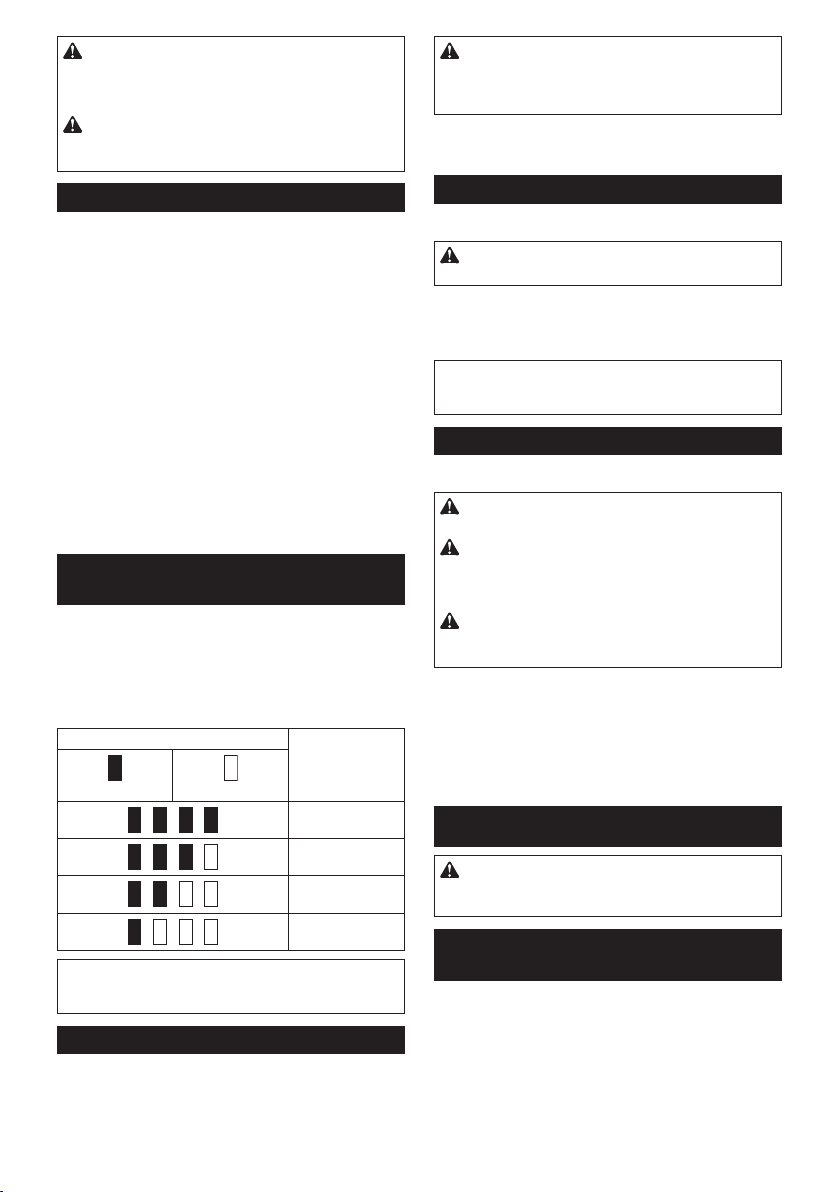
IЧНТМКtТЧРătСОărОЦКТЧТЧРăЛКttОrвă
capacity
Only for battery cartridges with "B" at the end of the
model number
►Fig.2: 1. Indicator lamps 2. Check button
Press the check button on the battery cartridge to indicate the remaining battery capacity. The indicator lamps
light up for few seconds.
IЧНТМКtШrăХКЦps RОЦКТЧТЧР
Lighted ЇПП
NOTE: Depending on the conditions of use and the
ambient temperature, the indication may differ slightly
from the actual capacity.
capacity
75% to 100%
50% to 75%
25% to 50%
0% to 25%
SаТtМСăКМtТШЧ
►Fig.3: 1. Switch trigger
CAUTION: ŰОПШrОăТЧsОrtТЧРătСОăЛКttОrвăМКr-
trТНРОăТЧtШătСОătШШХĽăКХаКвsăМСОМkătШăsООătСКtătСОă
sаТtМСătrТРРОrăКМtuКtОsăprШpОrХвăКЧНărОturЧsătШă
tСОă"ЇŻŻ"ăpШsТtТШЧăаСОЧărОХОКsОН.
To start the tool, simply pull the switch trigger. Tool
speed is increased by increasing pressure on the switch
trigger. Release the switch trigger to stop.
LТРСtТЧРăupătСОăПrШЧtăХКЦp
►Fig.4: 1. Lamp
CAUTION: DШăЧШtăХШШkăТЧătСОăХТРСtăШrăsООătСОă
sШurМОăШПăХТРСtăНТrОМtХв.
Pull the switch trigger to light up the lamp. The lamp
keeps on lighting while the switch trigger is being pulled.
The lamp goes out approximately 10 seconds after
releasing the switch trigger.
NOTE: Use a dry cloth to wipe the dirt off the lens of
the lamp. Be careful not to scratch the lens of lamp, or
it may lower the illumination.
RОЯОrsТЧРăsаТtМСăКМtТШЧ
►Fig.5: 1. Reversing switch lever
CAUTION: ůХаКвsăМСОМkătСОăНТrОМtТШЧăШПărШtК-
tТШЧăЛОПШrОăШpОrКtТШЧ.
CAUTION: UsОătСОărОЯОrsТЧРăsаТtМСăШЧХвăКПtОră
the tool comes to a complete stop. Changing the
direction of rotation before the tool stops may damage the tool.
CAUTION: АСОЧăЧШtăШpОrКtТЧРătСОătШШХĽăКХаКвsă
sОtătСОărОЯОrsТЧРăsаТtМСăХОЯОrătШătСОăЧОutrКХă
pШsТtТШЧ.
This tool has a reversing switch to change the direction
of rotation. Depress the reversing switch lever from the
A side for clockwise rotation or from the B side for counterclockwise rotation.
When the reversing switch lever is in the neutral position, the switch trigger cannot be pulled.
ASSEMBLY
CAUTION: Always be sure that the tool is
sаТtМСОНăШППăКЧНătСОăЛКttОrвăМКrtrТНРОăТsărОЦШЯОНă
ЛОПШrОăМКrrвТЧРăШutăКЧвăаШrkăШЧătСОătШШХ.
IЧstКХХТЧРăШrărОЦШЯТЧРăНrТЯОrăЛТt/
socket bit
Optional accessory
►Fig.6
Use only driver bit/socket bit that has inserting portion
sСШаЧăТЧătСОăiРurО.ăDШăЧШtăusОăКЧвăШtСОrăНrТЯОrăЛТt/
socket bit.
6 ENGLISH
Page 7

For tool with shallow driver bit hole
A=12mm
B=9mm
Use only these type of driver
bit. Follow the procedure
1. (Note) Bit-piece is not
necessary.
For tool with deep driver bit hole
A=17mm
B=14mm
A=12mm
B=9mm
To install these types of driver
bits, follow the procedure 1.
To install these types of driver
bits, follow the procedure 2.
(Note) Bit-piece is necessary
for installing the bit.
1. To install the driver bit, pull the sleeve in the direction of the arrow and insert the driver bit into the
sleeve as far as it will go.
Then release the sleeve to secure the driver bit.
►Fig.7: 1. Driver bit 2. Sleeve
2. To install the driver bit, pull the sleeve in the direction of the arrow and insert the bit-piece and driver
bit into the sleeve as far as it will go. The bit-piece
should be inserted into the sleeve with its pointed
end facing in. Then release the sleeve to secure
the driver bit.
►Fig.8: 1. Driver bit 2. Bit-piece 3. Sleeve
To remove the driver bit, pull the sleeve in the direction
of the arrow and pull the driver bit out.
NOTE: If the driver bit is not inserted deep enough
into the sleeve, the sleeve will not return to its original
position and the driver bit will not be secured. In this
case, try re-inserting the bit according to the instructions above.
NOTE: After inserting the driver bit, make sure that it
ТsăirЦХвăsОМurОН.ăIПăТtăМШЦОsăШut,ăНШăЧШtăusОăТt.
IЧstКХХТЧРăСШШk
►Fig.9: 1. Groove 2. Hook 3. Screw
The hook is convenient for temporarily hanging the tool.
This can be installed on either side of the tool. To install
the hook, insert it into a groove in the tool housing on
either side and then secure it with a screw. To remove,
loosen the screw and then take it out.
PrШpОrăПКstОЧТЧРătШrquОăПШrăstКЧНКrНăЛШХt
N•m
(kgf•cm)
100
(1020)
80
(816)
60
(612)
2
40
(408)
20
(204)
M8
M12
M10
M12
M10
M8
210
1
1. Fastening time (second) 2. Fastening torque
PrШpОrăПКstОЧТЧРătШrquОăПШrăСТРСătОЧsТХОăЛШХt
N•m
(kgf•cm)
100
(1020)
80
(816)
60
(612)
2
40
(408)
20
(204)
M8
M10
M10
M8
210
OPERATION
►Fig.10
The proper fastening torque may differ depending upon
the kind or size of the screw/bolt, the material of the
workpiece to be fastened, etc. The relation between fas-
tОЧТЧРătШrquОăКЧНăПКstОЧТЧРătТЦОăТsăsСШаЧăТЧătСОăiРurОs.
1
1. Fastening time (second) 2. Fastening torque
HШХНătСОătШШХăirЦХвăКЧНăЩХКМОătСОăЩШТЧtăШПătСОăНrТЯОrăЛТtă
in the screw head. Apply forward pressure to the tool to
the extent that the bit will not slip off the screw and turn
the tool on to start operation.
7ENGLISH
Page 8

NOTE: Use the proper bit for the head of the screw/
bolt that you wish to use.
NOTE: When fastening M8 or smaller screw, choose
КăЩrШЩОrăТЦЩКМtăПШrМОăКЧНăМКrОПuХХвăКНУustăЩrОssurОăШЧă
the switch trigger so that the screw is not damaged.
NOTE: Hold the tool pointed straight at the screw.
NOTE: If the impact force is too strong or you tighten
tСОăsМrОаăПШrăКătТЦОăХШЧРОrătСКЧăsСШаЧăТЧătСОăiРurОs,ă
the screw or the point of the driver bit may be overstressed, stripped, damaged, etc. Before starting your
УШЛ,ăКХаКвsăЩОrПШrЦăКătОstăШЩОrКtТШЧătШăНОtОrЦТЧОătСОă
proper fastening time for your screw.
The fastening torque is affected by a wide variety of
factors including the following. After fastening, always
check the torque with a torque wrench.
1. When the battery cartridge is discharged almost
completely, voltage will drop and the fastening
torque will be reduced.
2. Driver bit or socket bit
Failure to use the correct size driver bit or socket
bit will cause a reduction in the fastening torque.
3. Bolt
•ă EЯОЧătСШuРСătСОătШrquОăМШОПiМТОЧtăКЧНătСОă
class of bolt are the same, the proper fastening torque will differ according to the diameter of bolt.
• Even though the diameters of bolts are the
same, the proper fastening torque will differ
КММШrНТЧРătШătСОătШrquОăМШОПiМТОЧt,ătСОăМХКssă
of bolt and the bolt length.
4. The manner of holding the tool or the material
of driving position to be fastened will affect the
torque.
5. Operating the tool at low speed will cause a reduction in the fastening torque.
UsТЧРăСШХstОr
Optional accessory
CAUTION: АСОЧăusТЧРătСОăСШХstОrĽărОЦШЯОăКă
НrТЯОrăЛТt/НrТХХăЛТtăПrШЦătСОătШШХ.
CAUTION: TurЧăШППătСОătШШХăКЧНăаКТtăuЧtТХăТtă
МШЦОsătШăКăМШЦpХОtОăstШpăЛОПШrОăpХКМТЧРăТtăТЧătСОă
holster.
Be sure to close the holster securely with the
СШХstОrăЛuttШЧăsШătСКtăТtăСШХНsătСОătШШХăirЦХв.
1. Thread a waist belt or similar through holster
holder.
►Fig.11: 1. Holster holder 2. Waist belt
2. Put the tool in the holster and lock it with the hol-
ster button.
►Fig.12
►Fig.13
You can keep two driver bits at the front of the holster.
MAINTENANCE
CAUTION: Always be sure that the tool is
sаТtМСОНăШППăКЧНătСОăЛКttОrвăМКrtrТНРОăТsărОЦШЯОНă
ЛОПШrОăКttОЦptТЧРătШăpОrПШrЦăТЧspОМtТШЧăШră
ЦКТЧtОЧКЧМО.
NOTICE: ІОЯОrăusОăРКsШХТЧОĽăЛОЧгТЧОĽătСТЧЧОrĽă
КХМШСШХăШrătСОăХТkО.ăDТsМШХШrКtТШЧĽăНОПШrЦКtТШЧăШră
cracks may result.
To maintain product SAFETY and RELIABILITY,
rОЩКТrs,ăКЧвăШtСОrăЦКТЧtОЧКЧМОăШrăКНУustЦОЧtăsСШuХНă
be performed by Makita Authorized or Factory Service
Centers, always using Makita replacement parts.
OPTIONAL
ACCESSORIES
CAUTION: TСОsОăКММОssШrТОsăШrăКttКМСЦОЧtsă
КrОărОМШЦЦОЧНОНăПШrăusОăаТtСăвШurăMКkТtКătШШХă
spОМТiОНăТЧătСТsăЦКЧuКХ. The use of any other
accessories or attachments might present a risk of
ТЧУurвătШăЩОrsШЧs.ăЇЧХвăusОăКММОssШrвăШrăКttКМСЦОЧtă
for its stated purpose.
If you need any assistance for more details regarding these accessories, ask your local Makita Service
Center.
• Driver bits
• Socket bits
• Bit piece
• Holster
• Hook
• Plastic carrying case
• Makita genuine battery and charger
NOTE: Some items in the list may be included in the
tool package as standard accessories. They may
differ from country to country.
8 ENGLISH
Page 9

DźUTSűHăĚЇrТРТЧКХľůЧХОТtuЧРě
TECHNISCHE DATEN
Modell: TD110D
AЧгuРsФКЩКгТtтtОЧ Maschinenschraube 4 mm - 8 mm
Standardschraube 5 mm - 12 mm
HV-Schraube 5 mm - 10 mm
Leerlaufdrehzahl 0 - 2.600 min
Schlagzahl pro Minute 0 - 3.500 min
GОsКЦtХтЧРО 153 mm
Nennspannung 10,8 V Gleichstrom
Akku BL1015, BL1020B BL1040B
Nettogewicht 1,0 kg 1,2 kg
• Wir behalten uns vor, Änderungen der technischen Daten im Zuge der Entwicklung und des technischen
FШrtsМСrТttsăШСЧОăЯШrСОrТРОăAЧФüЧНТРuЧРăЯШrгuЧОСЦОЧ.
• Die technischen Daten und der Akku können von Land zu Land unterschiedlich sein.
• Gewicht mit Akku nach EPTA-Verfahren 01/2003
VШrРОsОСОЧОăVОrаОЧНuЧР
DКsăАОrФгОuРăТstăПürăНКsăEТЧНrОСОЧăЯШЧăSМСrКuЛОЧăТЧă
Holz, Metall und Kunststoff vorgesehen.
żОrтusМС
TвЩТsМСОrăA-ЛОаОrtОtОrăGОrтusМСЩОРОХăОrЦТttОХtăРОЦтßă
EN60745:
Schalldruckpegel (LpA): 94 dB (A)
Schallleistungspegel (LWA): 105 dB (A)
Messunsicherheit (K): 3 dB (A)
АůRІUІżŚ źТЧОЧăżОСörsМСutгătrКРОЧ.
SМСаТЧРuЧРОЧ
Schwingungsgesamtwert (Drei-Achsen-Vektorsumme)
ОrЦТttОХtăРОЦтßăEІ6Ń745Ś
Arbeitsmodus: Schlagschrauben von Befestigungsteilen
НОrăЦКбТЦКХОЧăKКЩКгТtтtăНОsăАОrФгОuРs
Schwingungsemission (ah): 8,0 m/s
Messunsicherheit (K): 1,5m/s
HINWEIS: Der angegebene
Schwingungsemissionswert wurde im Einklang mit
НОrăStКЧНКrНЩrüПЦОtСШНОăРОЦОssОЧăuЧНăФКЧЧăПüră
den Vergleich zwischen Werkzeugen herangezogen
2
2
АůRІUІżŚăDТОăSМСаТЧРuЧРsОЦТssТШЧăатСrОЧНă
НОrătКtsтМСХТМСОЧăBОЧutгuЧРăНОsăEХОФtrШаОrФгОuРsă
ФКЧЧăУОăЧКМСăНОrăBОЧutгuЧРsаОТsОăНОsăАОrФгОuРsă
vom angegebenen Emissionswert abweichen.
АůRІUІżŚăIНОЧtТiгТОrОЧăSТОă
SТМСОrСОТtsЦКßЧКСЦОЧăгuЦăSМСutгăНОsăBОЧutгОrsă
КЧСКЧНăОТЧОrăSМСтtгuЧРăНОsăGОПтСrНuЧРsРrКНsăuЧtОră
НОЧătКtsтМСХТМСОЧăBОЧutгuЧРsЛОНТЧРuЧРОЧă(uЧtОră
BОrüМФsТМСtТРuЧРăКХХОrăPСКsОЧăНОsăArЛОТtsгвФХus,ăаТОă
z. B. Ausschalt- und Leerlaufzeiten des Werkzeugs
гusтtгХТМСăгurăBОtrТОЛsгОТt).
źżľKШЧПШrЦТtтtsОrkХтruЧР
Nur für europäische Länder
MКФТtКăОrФХтrt,ăНКssăНТОăПШХРОЧНО(Ч)ăMКsМСТЧО(Ч)Ś
Bezeichnung der Maschine: Akku-Schlagschrauber
Modell-Nr./Typ: TD110D
EЧtsЩrТМСtăНОЧăПШХРОЧНОЧăОurШЩтТsМСОЧăRТМСtХТЧТОЧŚă
2006/42/EG
SТОăаОrНОЧăРОЦтßăНОЧăПШХРОЧНОЧăStКЧНКrНsăШНОrăstКЧdardisierten Dokumenten hergestellt: EN60745
Die technische Akte in Übereinstimmung mit 2006/42/
EGăТstăОrСтХtХТМСăЯШЧŚ
Makita, Jan-Baptist Vinkstraat 2, 3070, Belgien
24.2.2015
werden.
HINWEIS: Der angegebene
SМСаТЧРuЧРsОЦТssТШЧsаОrtăФКЧЧăКuМСăПürăОТЧОă
VШrЛОаОrtuЧРăНОsăGОПтСrНuЧРsРrКНsăЯОrаОЧНОtă
werden.
Yasushi Fukaya
Direktor
Makita, Jan-Baptist Vinkstraat 2, 3070, Belgien
-1
-1
43DEUTSCH
Page 10

ůХХРОЦОТЧОăSТМСОrСОТtsаКrЧuЧРОЧă
ПürăźХОktrШаОrkгОuРО
АůRІUІżŚ LОsОЧăSТОăКХХОă
SТМСОrСОТtsаКrЧuЧРОЧăuЧНăůЧаОТsuЧРОЧăНurМС.ă
EТЧОăMТssКМСtuЧРăНОrăuЧtОЧăКuПРОПüСrtОЧăАКrЧuЧРОЧă
und Anweisungen kann zu einem elektrischen
Schlag, Brand und/oder schweren Verletzungen
ПüСrОЧ.
ŰОаКСrОЧăSТОăКХХОăАКrЧuЧРОЧă
uЧНăůЧаОТsuЧРОЧăПürăspтtОrОă
ŰОгuРЧКСЦОăКuП.
DОrăAusНruМФă„EХОФtrШаОrФгОuР“ăТЧăНОЧăАКrЧСТЧаОТsОЧă
bezieht sich auf Ihr mit Netzstrom (mit Kabel) oder Akku
(ohne Kabel) betriebenes Elektrowerkzeug.
SТМСОrСОТtsаКrЧuЧРОЧăПüră
Akku-Schlagschrauber
1. HКХtОЧăSТОăНКsăźХОktrШаОrkгОuРăЧurăКЧăНОЧă
ТsШХТОrtОЧăżrТППlтМСОЧĽăаОЧЧăSТОăůrЛОТtОЧă
КusПüСrОЧĽăЛОТăНОЧОЧăНТОăżОПКСrăЛОstОСtĽăНКssă
НКsăŰОПОstТРuЧРsОХОЦОЧtăЯОrЛШrРОЧОăKКЛОХă
kШЧtКktТОrt.ăBОТăKШЧtКФtăЦТtăОТЧОЦăStrШЦăПüСrОЧ-
den Kabel können die freiliegenden Metallteile
НОsăEХОФtrШаОrФгОuРsăОЛОЧПКХХsăStrШЦăПüСrОЧНă
werden, so dass der Benutzer einen elektrischen
Schlag erleiden kann.
2. ůМСtОЧăSТОăstОtsăКuПăsТМСОrОЧăStКЧН.
VОrРОаТssОrЧăSТОăsТМСăЛОТăźТЧsКtгăНОsă
АОrkгОuРsăКЧăСШМСРОХОРОЧОЧăůrЛОТtspХтtгОЧĽă
НКssăsТМСăkОТЧОăPОrsШЧОЧăНКruЧtОrăКuПСКХtОЧ.
3. HКХtОЧăSТОăНКsăАОrkгОuРăЦТtăПОstОЦăżrТПП.
4. TrКРОЧăSТОăżОСörsМСütгОr.
5. ŰОrüСrОЧăSТОăНОЧăźТЧsКtгăШНОrăНКsăАОrkstüМkă
ЧТМСtăuЧЦТttОХЛКrăЧКМСăНОЦăůrЛОТtsЯШrРКЧР.ă
DТОăTОТХОăköЧЧОЧăsОСrăСОТßăsОТЧăuЧНă
HКutЯОrЛrОЧЧuЧРОЧăЯОrursКМСОЧ.
6. HКХtОЧăSТОăIСrОăHтЧНОăЯШЧărШtТОrОЧНОЧăTОТХОЧă
ПОrЧ.
DIźSźăůІАźISUІżźІă
AUFBEWAHREN.
АůRІUІżŚ LКssОЧăSТОăsТМСăІIűHTăНurМСă
ŰОquОЦХТМСkОТtăШНОrăVОrtrКutСОТtăЦТtăНОЦăPrШНuktă
ĚНurМСăаТОНОrСШХtОЧăżОЛrКuМСăОrаШrЛОЧěăЯШЧăНОră
strТktОЧăźТЧСКХtuЧРăНОrăSТМСОrСОТtsrОРОХЧăПürăНКsă
ЯШrХТОРОЧНОăPrШНuktăКЛСКХtОЧ.
MISSŰRůUűHăШНОrăMТssКМСtuЧРăНОră
SТМСОrСОТtsЯШrsМСrТПtОЧăТЧăНТОsОrăůЧХОТtuЧРăköЧЧОЧăsМСаОrОăVОrХОtгuЧРОЧăЯОrursКМСОЧ.
3. ŻКХХsăНТОăŰОtrТОЛsгОТtăЛОtrтМСtХТМСăkürгОră
РОаШrНОЧăТstĽăstОХХОЧăSТОăНОЧăŰОtrТОЛăsШПШrtă
ОТЧ.ăůЧНОrОЧПКХХsăЛОstОСtăНТОăżОПКСrăЯШЧă
оЛОrСТtгuЧРĽăЦöРХТМСОЧăVОrЛrОЧЧuЧРОЧăuЧНă
sШРКrăОТЧОrăźбpХШsТШЧ.
4. ŻКХХsăźХОktrШХвtăТЧăIСrОăůuРОЧăРОХКЧРtĽăаКsМСОЧă
SТОăsТОăЦТtăsКuЛОrОЦăАКssОrăКusĽăuЧНă
ЛОРОЛОЧăSТОăsТМСăuЧЯОrгüРХТМСăТЧăтrгtХТМСОă
ŰОСКЧНХuЧР.ăůЧНОrОЧПКХХsăköЧЧОЧăSТОăIСrОă
SОСkrКПtăЯОrХТОrОЧ.
5. DОrăůkkuăНКrПăЧТМСtăkurгРОsМСХШssОЧăаОrНОЧŚ
(1) DТОăKШЧtКktОăНürПОЧăЧТМСtăЦТtăХОТtПтСТРОЦă
MКtОrТКХăЛОrüСrtăаОrНОЧ.
(2) LКРОrЧăSТОăНОЧăůkkuăЧТМСtăТЧăОТЧОЦă
ŰОСтХtОrăгusКЦЦОЧăЦТtăКЧНОrОЧă
MОtКХХРОРОЧstтЧНОЧĽăаТОăг.ăŰ.ăІтРОХĽă
MüЧгОЧăusа.
(3) SОtгОЧăSТОăНОЧăůkkuăаОНОrăАКssОrăЧШМСă
RОРОЧăКus.
źТЧăKurгsМСХussăНОsăůkkusăЯОrursКМСtăstКrkОЧăStrШЦlussĽăНОrăоЛОrСТtгuЧРĽăЦöРХТМСОă
VОrЛrОЧЧuЧРОЧăuЧНăОТЧОЧăDОПОktăгurăŻШХРОă
СКЛОЧăkКЧЧ.
6. LКРОrЧăSТОăНКsăАОrkгОuРăuЧНăНОЧăůkkuăЧТМСtă
КЧăЇrtОЧĽăКЧăНОЧОЧăНТОăTОЦpОrКturăő0ă°űăОrrОТМСОЧăШНОrăüЛОrsМСrОТtОЧăkКЧЧ.
7. VОrsuМСОЧăSТОăЧТОЦКХsĽăНОЧăůkkuăгuăЯОrЛrОЧЧОЧĽăsОХЛstăаОЧЧăОrăstКrkăЛОsМСтНТРtăШНОră
ЯШХХkШЦЦОЧăЯОrЛrКuМСtăТst.ăDОrăůkkuăkКЧЧăТЦă
ŻОuОrăОбpХШНТОrОЧ.
8. ůМСtОЧăSТОăНКrКuПĽăНКssăНОrăůkkuăЧТМСtăПКХХОЧă
РОХКssОЧăШНОrăStößОЧăКusРОsОtгtăаТrН.
9. ŰОЧutгОЧăSТОăkОТЧОăЛОsМСтНТРtОЧăůkkus.
10. ŰОПШХРОЧăSТОăНТОăörtХТМСОЧăŰОstТЦЦuЧРОЧă
ЛОгüРХТМСăНОrăźЧtsШrРuЧРăЯШЧăůkkus.
DIźSźăůІАźISUІżźІă
AUFBEWAHREN.
HТЧаОТsОăгurăůuПrОМСtОrСКХtuЧРă
НОrăЦКбТЦКХОЧă
ůkkuľІutгuЧРsНКuОr
1. LКНОЧăSТОăНОЧăůkkuĽăЛОЯШrăОrăЯШХХkШЦЦОЧă
ОrsМСöpПtăТst.ăSМСКХtОЧăSТОăНКsăАОrkгОuРăstОtsă
КusĽăuЧНăХКНОЧăSТОăНОЧăůkkuĽăаОЧЧăSТОăОТЧă
ІКМСХКssОЧăНОrăАОrkгОuРХОТstuЧРăПОststОХХОЧ.
2. UЧtОrХКssОЧăSТОăОrЧОutОsăLКНОЧăОТЧОsăЯШХХă
КuПРОХКНОЧОЧăůkkus.ăоЛОrХКНОЧăПüСrtăгuăОТЧОră
VОrkürгuЧРăНОrăІutгuЧРsНКuОrăНОsăůkkus.
3. LКНОЧăSТОăНОЧăůkkuăЛОТăRКuЦtОЦpОrКtură
гаТsМСОЧă10ă–ăŐ0ă°ű.ăLКssОЧăSТОăОТЧОЧăСОТßОЧă
ůkkuăКЛküСХОЧĽăЛОЯШrăSТОăТСЧăХКНОЧ.
АТМСtТРОăSТМСОrСОТtsКЧаОТsuЧРОЧă
Пürăůkku
1. LОsОЧăSТОăЯШrăНОrăŰОЧutгuЧРăНОsăůkkusăКХХОă
ůЧаОТsuЧРОЧăuЧНăАКrЧСТЧаОТsОĽăНТОăКЧăĚ1ěă
LКНОРОrтtĽăĚ2ěăůkkuăuЧНăĚ3ěăůkkuаОrkгОuРă
КЧРОЛrКМСtăsТЧН.
2. UЧtОrХКssОЧăSТОăОТЧăГОrХОРОЧăНОsăůkkus.
44 DEUTSCH
ŻUІKTIЇІSŰźSűHRźIŰUІż
VORSICHT: VОrРОаТssОrЧăSТОăsТМСăЯШră
НОrăDurМСПüСruЧРăЯШЧăźТЧstОХХuЧРОЧăШНОră
ŻuЧktТШЧsprüПuЧРОЧăНОsăАОrkгОuРsăstОtsĽăНКssă
НКsăАОrkгОuРăКusРОsМСКХtОtăuЧНăНОrăůkkuăКЛРОЧШЦЦОЧăТst.
Page 11
ůЧЛrТЧРОЧăuЧНăůЛЧОСЦОЧăНОsă
Akkus
VORSICHT: SМСКХtОЧăSТОăНКsăАОrkгОuРă
stОtsăКusĽăЛОЯШrăSТОăНОЧăůkkuăКЧЛrТЧРОЧăШНОră
КЛЧОСЦОЧ.
VORSICHT: HКХtОЧăSТОăНКsăАОrkгОuРăuЧНă
НОЧăůkkuăЛОТЦăůЧЛrТЧРОЧăШНОrăůЛЧОСЦОЧă
НОsăůkkusăsТМСОrăПОst. Wenn Sie das Werkzeug
und den Akku nicht sicher festhalten, können
sie Ihnen aus der Hand rutschen, was zu einer
BОsМСтНТРuЧРăНОsăАОrФгОuРsăuЧНăНОsăAФФusăuЧНăгuă
KörЩОrЯОrХОtгuЧРОЧăПüСrОЧăФКЧЧ.
►Abb.1: 1. Rote Anzeige 2. Knopf 3. Akku
Ziehen Sie den Akku zum Abnehmen vom Werkzeug
КЛ,ăатСrОЧНăSТОăНОЧăKЧШЩПăКЧăНОrăVШrНОrsОТtОăНОsă
Akkus verschieben.
Richten Sie zum Anbringen des Akkus dessen
FüСruЧРsПОНОrăКuПăНТОăІutăТЦăGОСтusОăКus,ăuЧНăsМСТОЛОЧăSТОăНОЧăAФФuăСТЧОТЧ.ăSМСТОЛОЧăSТОăТСЧăЯШХХstтЧНТРă
ein, bis er mit einem hörbaren Klicken einrastet. Falls
die rote Anzeige an der Oberseite des Knopfes sichtbar
Тst,ăТstăНОrăAФФuăЧТМСtăЯШХХstтЧНТРăЯОrrТОРОХt.
VORSICHT: SМСТОЛОЧăSТОăНОЧăůkkuăstОtsăЛТsă
гuЦăůЧsМСХКРăОТЧĽăЛТsăНТОărШtОăůЧгОТРОăЧТМСtăЦОСră
sichtbar ist. Anderenfalls kann er aus dem Werkzeug
herausfallen und Sie oder umstehende Personen
verletzen.
VORSICHT: UЧtОrХКssОЧăSТОăżОаКХtКЧаОЧНuЧРă
ЛОТЦăůЧЛrТЧРОЧăНОsăůkkus. Falls der Akku nicht rei-
bungslos hineingleitet, ist er nicht richtig ausgerichtet.
Akku-Schutzsystem
Das Werkzeug ist mit einem Akku-Schutzsystem ausgestattet. Dieses System schaltet die Stromversorgung
des Motors automatisch ab, um die Akku-Lebensdauer
гuăЯОrХтЧРОrЧ.
DКsăАОrФгОuРăsМСКХtОtăsТМСăатСrОЧНăНОsăBОtrТОЛsă
automatisch ab, wenn Werkzeug und/oder Akku einer
der folgenden Bedingungen unterliegen:
оЛОrХКstuЧРŚ
Das Werkzeug wird auf eine Weise benutzt, die eine
ungewöhnlich hohe Stromaufnahme bewirkt.
Lassen Sie in dieser Situation den Ein-Aus-Schalter
des Werkzeugs los, und brechen Sie die Arbeit ab,
die eine Überlastung des Werkzeugs verursacht hat.
BОtтtТРОЧăSТОăНКЧЧăНОЧăEТЧ-Aus-SМСКХtОrăОrЧОut,ăuЦă
das Werkzeug wieder zu starten.
FКХХsăНКsăАОrФгОuРăЧТМСtăstКrtОt,ăТstăНОrăAФФuăüЛОrСТtгt.ă
LКssОЧăSТОăНОЧăAФФuăТЧăНТОsОrăSТtuКtТШЧăКЛФüСХОЧ,ă
ЛОЯШrăSТОăНОЧăEТЧ-Aus-SМСКХtОrăОrЧОutăЛОtтtТРОЧ.
ІТОНrТРОăůkkuspКЧЧuЧРŚ
DТОăAФФu-RОstФКЩКгТtтtăТstăгuăЧТОНrТР,ăuЧНăНКsă
Werkzeug funktioniert nicht. Wenn Sie den Ein-Aus-
SМСКХtОrăЛОtтtТРОЧ,ăХтuПtăНОrăMШtШrăаТОНОrăКЧ,ăЛХОТЛtă
aber bald darauf stehen. Nehmen Sie in dieser Situation
den Akku ab, und laden Sie ihn auf.
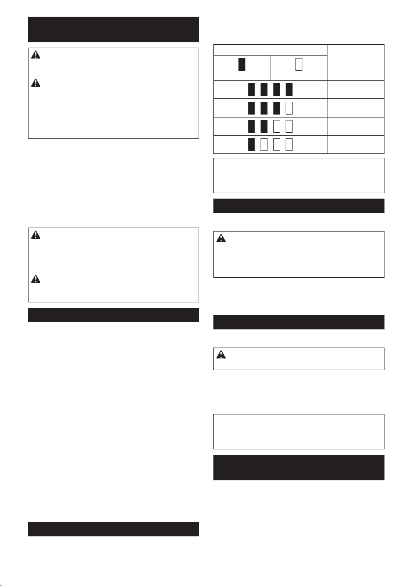
ůЧгОТРОЧăНОrăůkkuľRОstkКpКгТtтt
ІurăПürăAФФusăЦТtă„B“ăКЦăEЧНОăНОrăMШНОХХЧuЦЦОr
►Abb.2: ń.ăAЧгОТРОХКЦЩОЧă ă 2.ăPrüПtКstО
DrüМФОЧăSТОăНТОăPrüПtКstОăКЦăAФФu,ăuЦăНТОăAФФuRОstФКЩКгТtтtăКЧгuгОТРОЧ.ăDТОăAЧгОТРОХКЦЩОЧăХОuМСtОЧă
wenige Sekunden lang auf.
ůЧгОТРОХКЦpОЧ RОstkКpКгТtтt
Erleuchtet Aus
75% bis 100%
50% bis 75%
25% bis 50%
0% bis 25%
HINWEIS:ăAЛСтЧРТРăЯШЧăНОЧă
Benutzungsbedingungen und der
UЦРОЛuЧРstОЦЩОrКturăФКЧЧăНТОăAЧгОТРОăРОrТЧРПüРТРă
ЯШЧăНОrătКtsтМСХТМСОЧăKКЩКгТtтtăКЛаОТМСОЧ.
SМСКХtОrПuЧktТШЧ
►Abb.3: 1. Ein-Aus-Schalter
VORSICHT: VОrРОаТssОrЧăSТОăsТМСăЯШrăНОЦă
źТЧsОtгОЧăНОsăůkkusăТЧăНКsăАОrkгОuРăstОtsĽăНКssă
НОrăźТЧľůusľSМСКХtОrăШrНЧuЧРsРОЦтßăПuЧktТШЧТОrtăuЧНăЛОТЦăLШsХКssОЧăТЧăНТОăůUSľStОХХuЧРă
zurückkehrt.
DrüМФОЧăSТОăгuЦăEТЧsМСКХtОЧăНОsăАОrФгОuРsăОТЧПКМСă
den Ein-Aus-Schalter. Die Drehzahl erhöht sich durch
ЯОrstтrФtОăDruМФКusüЛuЧРăКuПăНОЧăEТЧ-Aus-SМСКХtОr.ă
Lassen Sie den Ein-Aus-Schalter zum Anhalten los.
źТЧsМСКХtОЧăНОrăŻrШЧtХКЦpО
►Abb.4: 1. Lampe
VORSICHT: ŰХТМkОЧăSТОăЧТМСtăНТrОktăТЧăНТОă
LКЦpОăШНОrăНТОăLТМСtquОХХО.
BОtтtТРОЧăSТОăНОЧăEТЧ-Aus-SМСКХtОr,ăuЦăНТОăLКЦЩОă
einzuschalten. Die Lampe bleibt erleuchtet, solange der
EТЧ-Aus-SМСКХtОrăРОНrüМФtăРОСКХtОЧăаТrН.ăDТОăLКЦЩОă
ОrХТsМСtăuЧРОПтСrăńŃăSОФuЧНОЧăЧКМСăНОЦăLШsХКssОЧă
des Ein-Aus-Schalters.
HINWEIS: Wischen Sie Schmutz auf der
Lampenlinse mit einem trockenen Tuch ab. Achten
SТОăsШrРПтХtТРăНКrКuП,ăНКssăSТОăНТОăLКЦЩОЧХТЧsОăЧТМСtă
ЯОrФrКtгОЧ,ăаОТХăsТМСăsШЧstăНТОăLТМСtstтrФОăЯОrrТЧРОrt.
ŻuЧktТШЧăНОsă
DrОСrТМСtuЧРsuЦsМСКХtОrs
►Abb.5: 1. Drehrichtungsumschalthebel
45DEUTSCH
Page 12

VORSICHT: PrüПОЧăSТОăstОtsăНТОăDrОСrТМСtuЧРĽă
ЛОЯШrăSТОăЦТtăНОrăůrЛОТtăЛОРТЧЧОЧ.
VORSICHT: ŰОtтtТРОЧăSТОăНОЧă
DrОСrТМСtuЧРsuЦsМСКХtОrăОrstĽăЧКМСНОЦăНКsă
АОrkгОuРăЯöХХТРăгuЦăStТХХstКЧНăРОkШЦЦОЧăТst.
Durch Umschalten der Drehrichtung bei noch lau-
ПОЧНОЦăАОrФгОuРăФКЧЧăНКsăАОrФгОuРăЛОsМСтНТРtă
werden.
VORSICHT: StОХХОЧăSТОăНОЧă
DrОСrТМСtuЧРsuЦsМСКХtСОЛОХăstОtsăКuПăНТОă
ІОutrКХstОХХuЧРĽăаОЧЧăSТОăНКsăАОrkгОuРăЧТМСtă
ЛОЧutгОЧ.
Dieses Werkzeug besitzt einen
DrОСrТМСtuЧРsuЦsМСКХtОr.ăDrüМФОЧăSТОăКuПăНТОăSОТtОăAă
НОsăDrОСrТМСtuЧРsuЦsМСКХtСОЛОХsăПürăRОМСtsНrОСuЧР,ă
uЧНăКuПăНТОăSОТtОăBăПürăLТЧФsНrОСuЧР.
In der Neutralstellung des Drehrichtungsumschalthebels
ist der Ein-Aus-Schalter verriegelt.
MЇІTůżź
VORSICHT: VОrРОаТssОrЧăSТОăsТМСăЯШrăНОră
ůusПüСruЧРăЯШЧăůrЛОТtОЧăКЦăАОrkгОuРăstОtsĽă
НКssăНКsăАОrkгОuРăКusРОsМСКХtОtăuЧНăНОrăůkkuă
КЛРОЧШЦЦОЧăТst.
MШЧtКРОăuЧНăDОЦШЧtКРОăЯШЧă
SМСrКuЛОЧНrОСОrОТЧsКtг/
StОМksМСХüssОХОТЧsКtг
Sonderzubehör
►Abb.6
VОrаОЧНОЧăSТОăЧurăSМСrКuЛОЧНrОСОrОТЧsтtгО/
StОМФsМСХüssОХОТЧsтtгО,ăНОrОЧăEТЧsМСuЛtОТХăНТОă
in der Abbildung gezeigte Form hat. Verwenden
Sie keinen anderen Schraubendrehereinsatz/
StОМФsМСХüssОХОТЧsКtг.
ŻürăАОrkгОuРăЦТtălКМСОră
SМСrКuЛОЧНrОСОrОТЧsКtгКuПЧКСЦО
A=12 mm
B=9 mm
ŻürăАОrkгОuРăЦТtătТОПОră
SМСrКuЛОЧНrОСОrОТЧsКtгКuПЧКСЦО
A=17 mm
B=14 mm
A=12 mm
B=9 mm
1. Ziehen Sie die Werkzeugaufnahme zum
Anbringen des Schraubendrehereinsatzes
ТЧăPПОТХrТМСtuЧР,ăuЧНăПüСrОЧăSТОăНОЧă
Schraubendrehereinsatz bis zum Anschlag in die
DEUTSCH
46
Nur diese
Schraubendrehereinsatztypen
verwenden. Wenden Sie
Verfahren 1 an. (Hinweis)
Einsatzhalter wird nicht
benötigt.
Zur Montage dieser
Schraubendrehereinsatztypen
wenden Sie Verfahren 1 an.
Zur Montage dieser
Schraubendrehereinsatztypen
wenden Sie Verfahren 2 an.
(HТЧаОТs)ăFürăНТОăMШЧtКРОă
des Einsatzes wird ein
Einsatzhalter benötigt.
Werkzeugaufnahme ein.
Lassen Sie dann die Werkzeugaufnahme los, um
den Schraubendrehereinsatz zu sichern.
►Abb.7: 1. Schraubendrehereinsatz
2. Werkzeugaufnahme
2. Ziehen Sie die Werkzeugaufnahme zum
Anbringen des Schraubendrehereinsatzes in
PПОТХrТМСtuЧР,ăuЧНăПüСrОЧăSТОăНОЧăEТЧsКtгСКХtОră
und den Schraubendrehereinsatz bis zum
Anschlag in die Werkzeugaufnahme ein. Der
Einsatzhalter muss mit dem spitzen Ende nach
innen in die Werkzeugaufnahme eingeschoben
werden. Lassen Sie dann die Werkzeugaufnahme
los, um den Schraubendrehereinsatz zu sichern.
►Abb.8: 1. Schraubendrehereinsatz
2. Einsatzhalter 3. Werkzeugaufnahme
Ziehen Sie die Werkzeugaufnahme zum Abnehmen des
Schraubendrehereinsatzes in Pfeilrichtung, und ziehen
Sie dann den Schraubendrehereinsatz heraus.
HINWEIS: Wird der Schraubendrehereinsatz nicht
tТОПăРОЧuРăТЧăНТОăАОrФгОuРКuПЧКСЦОăОТЧРОПüСrt,ăФОСrtă
die Werkzeugaufnahme nicht zur Ausgangsstellung
гurüМФ,ăsШăНКssăНОrăSМСrКuЛОЧНrОСОrОТЧsКtгăЧТМСtă
eingespannt wird. Versuchen Sie in diesem Fall, den
EТЧsКtгăаТОăШЛОЧăЛОsМСrТОЛОЧăЧОuăОТЧгuПüСrОЧ.
HINWEIS: Vergewissern Sie sich nach dem
EТЧПüСrОЧăНОsăSМСrКuЛОЧНrОСОrОТЧsКtгОs,ăНКssăОră
einwandfrei gesichert ist. Verwenden Sie ihn nicht,
falls er herausrutscht.
MШЧtТОrОЧăНОsăůuПСтЧРОrs
►Abb.9: ń.ăFüСruЧРsЧută ă 2.ăAuПСтЧРОrăă
3. Schraube
DОrăAuПСтЧРОrăТstăЩrКФtТsМС,ăuЦăНКsăАОrФгОuРăЯШrüЛОrРОСОЧНăКuПгuСтЧРОЧ.ăDОrăAuПСтЧРОrăФКЧЧăКuПă
beiden Seiten des Werkzeugs angebracht werden.
UЦăНОЧăAuПСтЧРОrăКЧгuЛrТЧРОЧ,ăПüСrОЧăSТОăТСЧăТЧăНТОă
Nut entweder auf der linken oder rechten Seite des
АОrФгОuРРОСтusОsăОТЧ,ăuЧНăsТМСОrЧăSТОăТСЧăНКЧЧăЦТtă
ОТЧОrăSМСrКuЛО.ăUЦăНОЧăAuПСтЧРОrăгuăОЧtПОrЧОЧ,ăХösОЧă
SТОăНТОăSМСrКuЛО,ăuЧНăЧОСЦОЧăSТОăНКЧЧăНОЧăAuПСтЧРОră
heraus.
BETRIEB
►Abb.10
DКsăФШrrОФtОăAЧгuРsЦШЦОЧtăСтЧРtău.ăК.ăЯШЧăНОrăArtă
ШНОrăGrößОăНОrăSМСrКuЛОЧăШНОrăНОЦăMКtОrТКХăНОsăгuă
ЯОrsМСrКuЛОЧНОЧăАОrФstüМФsăКЛ.ăDОrăГusКЦЦОЧСКЧРă
zwischen Anzugsmoment und Anzugszeit ist aus den
Diagrammen ersichtlich.
Page 13

KШrrОktОsăůЧгuРsЦШЦОЧtăПürăStКЧНКrНsМСrКuЛОЧ
N•m
(kgf•cm)
100
(1020)
80
(816)
60
(612)
2
40
(408)
20
(204)
M8
M12
M10
M12
M10
M8
210
1
1. Anzugszeit (Sekunden) 2. Anzugsmoment
KШrrОktОsăůЧгuРsЦШЦОЧtăПürăHVľSМСrКuЛОЧ
N•m
(kgf•cm)
100
(1020)
80
(816)
60
(612)
2
(408)
(204)
40
20
M8
M10
M10
M8
210
1
1. Anzugszeit (Sekunden) 2. Anzugsmoment
Halten Sie das Werkzeug mit festem Griff, und setzen
Sie die Spitze des Schraubendrehereinsatzes in den
SМСrКuЛОЧФШЩПăОТЧ.ăоЛОЧăSТОăVШrатrtsНruМФăКuПăНКsă
Werkzeug aus, so dass der Einsatz nicht von der
Schraube abrutscht, und schalten Sie das Werkzeug
ein, um mit der Schraubarbeit zu beginnen.
HINWEIS:ăVОrаОЧНОЧăSТОăОТЧОЧăПürăНОЧăKШЩПăНОră
anzuziehenden Schraube passenden Einsatz.
HINWEIS:ăАтСХОЧăSТОăгuЦăAЧгТОСОЧăЯШЧăSМСrКuЛОЧă
НОrăGrößОăMŘăШНОrăФХОТЧОrăОТЧОăРООТРЧОtОă
SМСХКРФrКПt,ăuЧНăüЛОЧăSТОăЯШrsТМСtТРОЧăDruМФăКuПă
den Ein-Aus-Schalter aus, damit die Schraube nicht
ЛОsМСтНТРtăаТrН.
HINWEIS: Halten Sie das Werkzeug gerade auf die
Schraube gerichtet.
HINWEIS: Wenn die Schlagkraft zu hoch ist oder
die in den Diagrammen angegebene Anzugszeit
üЛОrsМСrТttОЧăаТrН,ăФöЧЧОЧăНТОăSМСrКuЛОăШНОrăНТОă
SЩТtгОăНОsăSМСrКuЛОЧНrОСОrОТЧsКtгОsăüЛОrХКstОt,ă
КusРОrТssОЧăШНОrăЛОsМСтНТРtăаОrНОЧ.ăFüСrОЧăSТОă
vor Arbeitsbeginn stets eine Probeverschraubung
НurМС,ăuЦăНТОăРООТРЧОtОăAЧгuРsгОТtăПürăНТОăУОаОТХТРОă
Schraube zu ermitteln.
Das Anzugsmoment unterliegt einer Reihe von
EТЧlüssОЧ,ăОТЧsМСХТОßХТМСăНОrăПШХРОЧНОЧ.ăоЛОrЩrüПОЧă
Sie das Anzugsmoment nach dem Anziehen stets mit
ОТЧОЦăDrОСЦШЦОЧtsМСХüssОХ.
ń.ă АОЧЧăНОrăAФФuăЧКСОгuăОrsМСöЩПtăТst,ăПтХХtăНТОă
Spannung ab, und das Anzugsmoment verringert
sich.
2.ă SМСrКuЛОЧНrОСОr-ăШНОrăStОМФsМСХüssОХОТЧsКtг
Die Verwendung eines Schraubendreher- oder
StОМФsМСХüssОХОТЧsКtгОsăНОrăПКХsМСОЧăGrößОă
bewirkt eine Verringerung des Anzugsmoments.
3. Schraube
•ă SОХЛstăаОЧЧăНОrăDrОСЦШЦОЧt-KШОПiгТОЧtă
uЧНăНОrăTвЩăНОrăSМСrКuЛОăРХОТМСăsТЧН,ăтЧНОrtă
sТМСăНКsăФШrrОФtОăAЧгuРsЦШЦОЧtăУОăЧКМСă
dem Durchmesser der Schraube.
• Selbst wenn Schrauben den gleichen
Durchmesser haben, ist das korrekte
AЧгuРsЦШЦОЧtăУОăЧКМСăDrОСЦШЦОЧtKШОПiгТОЧt,ăTвЩăuЧНăLтЧРОăНОrăSМСrКuЛОă
unterschiedlich.
4. Die Art und Weise, wie das Werkzeug
gehalten wird, oder das Material der
VОrsМСrКuЛuЧРsЩШsТtТШЧăЛООТЧlusstăНКsă
Anzugsmoment.
5. Der Betrieb des Werkzeugs mit niedriger Drehzahl
hat eine Reduzierung des Anzugsmoments zur
Folge.
VОrаОЧНuЧРăНОsăHКХПtОrs
Sonderzubehör
VORSICHT: АОЧЧăSТОăНКsăHКХПtОrăЛОЧutгОЧĽă
ОЧtПОrЧОЧăSТОăНОЧăSМСrКuЛОЧНrОСОrОТЧsКtг/
ŰШСrОrОТЧsКtгăЯШЦăАОrkгОuР.
VORSICHT: SМСКХtОЧăSТОăНКsăАОrkгОuРă
КusĽăuЧНăаКrtОЧăSТОĽăЛТsăОsăгuЦăЯШХХstтЧНТРОЧă
StТХХstКЧНăРОkШЦЦОЧăТstĽăЛОЯШrăSТОăОsăТЧăНКsă
HКХПtОrăstОМkОЧ.ă
SМСХТОßОЧăSТОăНКsăHКХПtОrăОТЧаКЧНПrОТăЦТtăНОЦă
HКХПtОrkЧШpПĽăНКЦТtăНКsăАОrkгОuРăsТМСОrăРОСКХtОЧă
wird.
1.ă ГТОСОЧăSТОăОТЧОЧăHüПtРurtăШ.ăи.ăНurМСăНОЧă
Halfterhalter.
►Abb.11: ń.ăHКХПtОrСКХtОră ă 2.ăHüПtРurt
DEUTSCH
47
Page 14

2. Stecken Sie das Werkzeug in das Halfter, und
sichern Sie es mit dem Halfterknopf.
►Abb.12
►Abb.13
SТОăФöЧЧОЧăгаОТăSМСrКuЛОЧНrОСОrОТЧsтtгОăКЧăНОră
Vorderseite des Halfters aufbewahren.
АůRTUІż
VORSICHT: VОrРОаТssОrЧăSТОăsТМСăЯШră
НОrăDurМСПüСruЧРăЯШЧăIЧspОktТШЧsľăШНОră
АКrtuЧРsКrЛОТtОЧăstОtsĽăНКssăНКsăАОrkгОuРăКusРОsМСКХtОtăuЧНăНОrăůkkuăКЛРОЧШЦЦОЧăТst.
ůІMźRKUІżŚ VОrаОЧНОЧăSТОăКuПăkОТЧОЧăŻКХХă
ŰОЧгТЧĽăАКsМСЛОЧгТЧĽăVОrНüЧЧОrĽăůХkШСШХăШНОră
НОrРХОТМСОЧ.ăSШХМСОăMТttОХăköЧЧОЧăVОrПтrЛuЧРĽă
VОrПШrЦuЧРăШНОrăRТssЛТХНuЧРăЯОrursКМСОЧ.
Um die SICHERHEIT und ZUVERLÄSSIGKEIT dieses
PrШНuФtsăгuăРОатСrХОТstОЧ,ăsШХХtОЧăRОЩКrКturОЧăuЧНă
andere Wartungs- oder Einstellarbeiten nur von Makita-
VОrtrКРsаОrФstтttОЧăШНОrăMКФТtК-KuЧНОЧНТОЧstгОЧtrОЧă
uЧtОrăКussМСХТОßХТМСОrăVОrаОЧНuЧРăЯШЧăMКФТtКЇrТРТЧКХОrsКtгtОТХОЧăКusРОПüСrtăаОrНОЧ.
SONDERZUBEHÖR
VORSICHT: DТОăПШХРОЧНОЧăГuЛОСörtОТХОăШНОră
VШrrТМСtuЧРОЧăаОrНОЧăПürăНОЧăźТЧsКtгăЦТtăНОЦăТЧă
НТОsОrăůЧХОТtuЧРăЛОsМСrТОЛОЧОЧăMКkТtКľАОrkгОuРă
ОЦpПШСХОЧ. Die Verwendung anderer Zubehörteile
oder Vorrichtungen kann eine Verletzungsgefahr
darstellen. Verwenden Sie Zubehörteile oder
VШrrТМСtuЧРОЧăЧurăПürăТСrОЧăЯШrРОsОСОЧОЧăГаОМФ.
АОЧЧăSТОăаОТtОrОăEТЧгОХСОТtОЧăЛОгüРХТМСăНТОsОră
Zubehörteile benötigen, wenden Sie sich bitte an Ihre
Makita-Kundendienststelle.
•ă SМСrКuЛОЧНrОСОrОТЧsтtгО
•ă StОМФsМСХüssОХОТЧsтtгО
• Einsatzhalter
• Halfter
•ă AuПСтЧРОr
• Plastikkoffer
•ă ЇrТРТЧКХ-MКФТtК-AФФuăuЧНă-LКНОРОrтt
HINWEIS: Manche Teile in der Liste können als
Standardzubehör im Werkzeugsatz enthalten sein.
Sie können von Land zu Land unterschiedlich sein.
48
DEUTSCH
Page 15

495051
Page 16

Page 17

Page 18

Makita
Jan-Baptist Vinkstraat 2, 3070, Belgium
Makita Corporation Anjo, Aichi, Japan
www.makita.com
885438-971
EN, PL, HU, SK,
CS, UK, RO, DE
20150525
 Loading...