

Page 1
Your dealer /Votre revendeur/Su revendedor/Ihr Händler/Vostro rivenditore
Uw handelaar/ Seu revendedor/
Ο έμπορ ός σας
Instruction manual / Manuel d’utilsation
English 1 - 18
Français 19 - 36
E s p a ñ o l 37 - 55
D e u t s c h 57 - 74
I t a l i a n o 75 - 93
N e d e r l a n d s 95 - 113
P o rt u g u ê s 115 - 133
ελληνικός
135 - 145
AUTOMATIC LASER
LASER AUTOMATIQUE
SKR301
Page 2
192123
24 22 20
14
17
15
16
18
12
2
5
1
1
7
8
11
9
10
6
4
3
Page 3
SKR301
AUTOMATIC LASER
Operating Manual
Page 4

Table of contents
1. General information 3
1.1 Description
1.2 Technical Specifications
1.3 Overview
1.4 Overview of keypad
Although the SKR301 is very simple to use, we recommend that you
read this manual before operating the laser.
1. General information
1.1 Description
2. Operating instructions 5
2.1 Auto/Man key
2.2 Tilt key
2.3 Horizontal setup
2.4 Vertical setup
2.5 Squaring
2.6 Rotation speed
2.7 Using the chalk line
2.8 Using the scanning
2.9 Manual slope
3.0 Power
3. Checking and adjusting your SKR301 9
3.1 Horizontal checking and calibration
3.2 Vertical checking and calibration
4. Care and handling 12
5. Warranty 13
6. Accessories 13
6.1 Detector
6.2 Remote control
6.3 Mounts
6.4 Other Accessories
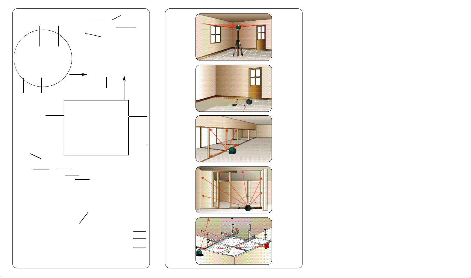
The SKR301 is an automatic visible laser that can be used for leveling, vertical alignment, plumbing and squaring. Applications include
installing suspended ceilings, technical flooring, partitions and a
variety of outdoor alignment work.
The SKR301 laser has these advanced features :
• Automatic self-leveling in both horizontal and vertical modes
• Choice of beams: rotating plane, scanning, chalk line, single
point or constant squaring
• Easy electronic calibration
• Square shot that’s left/right adjustable
Caution:
is manufactured to comply with the international rules of safety IEC
285. Although the power of the emission of the beam does not
exceed 1mW in Class II and 2mW in Class IIIa, the following cautions are recommended:
The SKR301 is a class II or IIIR (US version) laser and
Do not stare directly at the laser beam
2
3
Page 5
1.2 Technical Specifications
1.4 Overview of keypad
Recommended 1,000 ft. (300m) with detector
use (diameter)
Leveling accuracy
Leveling range + / – 8 %
Scanning angle From 3° to 34°
Laser diode 635 nm maximum
Power
Charging time 15 hours
Battery life
Size 6” x 6 1/2” x 6 3/4”
Rotation speed 0-90-150-300-450-600 rpm
Weatherproof Rain and dustproof (IP65)
0.010 % (+/– 1/8” at 100 feet
+/–10 mm at 100 m)
European version: 1mW, Class II
US version: 2mW, class IIIR
2 alkaline batteries (LR20 or D)
or rechargeable batteries
40 hours with rechargeable batteries
160 hours with alkaline batteries
(15 x 16 x 17 cm)
3 lbs (1.3 kg)
14. Laser rotation control to the left + speed control
Save calibration data
15. Laser rotation control to the right + speed control
Change calibration Axis
16. Moving the square shot to the right / Move beam down
17. Moving the square shot to the left / Move beam up
18. Capture window for remote control
19. Manual mode LED / Z Axis calibration indicator
20. Manual / Automatic
21. H.I Alert light / Y Axis calibration indicator
22. H.I Alert (Tilt)
23. Battery low light / X Axis calibration indicator
24. On/Off
Italics correspond to indication and keys used in calibration mode.
2. How to use your SKR301 laser
An overview of laser and keypad functions can be found in the
inside front cover.
The laser does a self-test when turned on. The beam blinks while the
laser is self-leveling. After it has leveled, the head will start to rotate.
2.1 Auto/Man key (20)
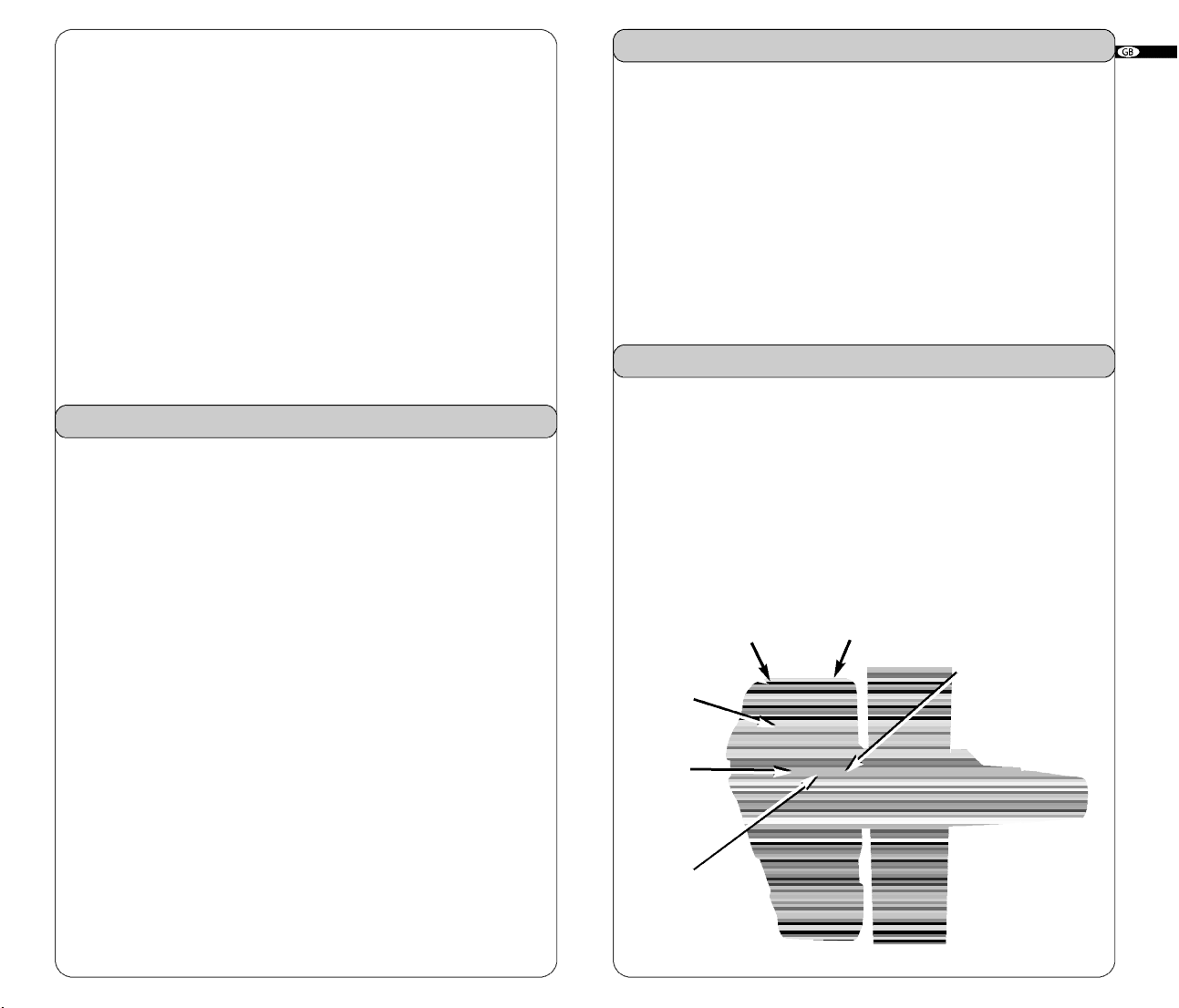
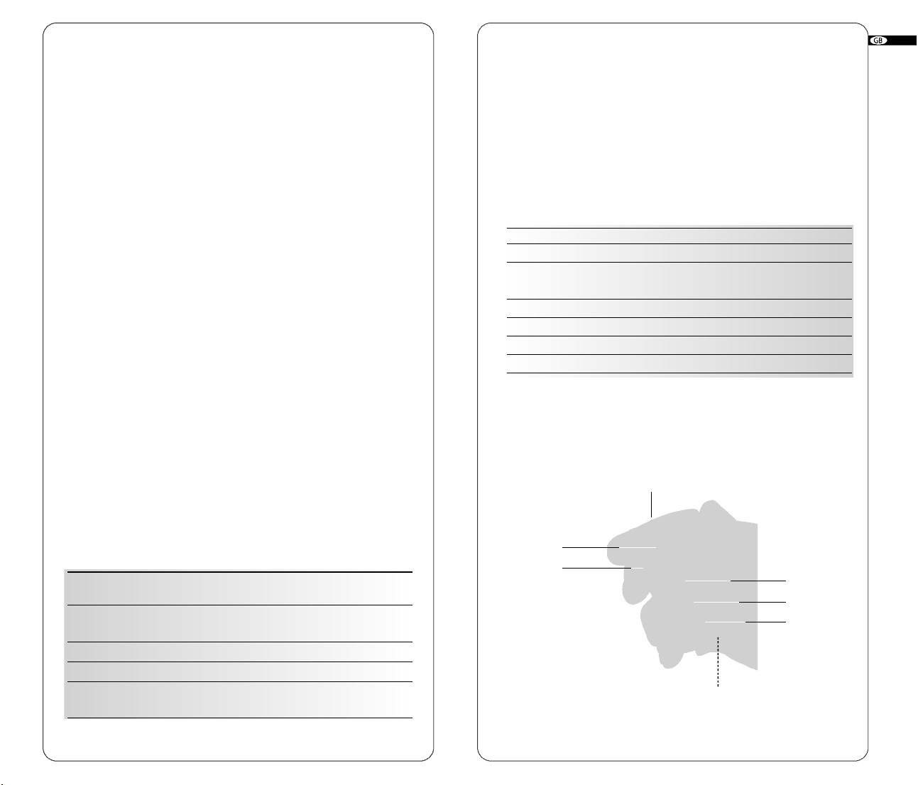
1.3 Overview
1. Rotating head
2. Plumb or square laser beam aperture
3. Laser beam aperture
4. Laser chalk line aperture
5. Arrow
6. 90° index mark (one of four)
7. Retractable foot for vertical setup
8. Adjustable feet for vertical setup
9. Batteries
10. Jack for battery charger
11. 5/8 - 11 mount
12. Top cover
4
• Auto: Automatic leveling
Default mode when laser is switched on
• Man: Manual use
The SKR301 laser is always in the automatic self-leveling mode
(auto) when turned on. Once the instrument has self-leveled, the laser
head will start rotating.
You can choose to have constant rotation by using the manual mode.
This way, the beam will rotate even if the instrument is not leveled
(necessary when working on inclined planes).
For safety, a red light will blink above the Auto/Manual button to
advise the user that the laser is in manual mode.
5
Page 6

2.2 Tilt key (22)
Tilt : H.I.-Alert mode. Will work only when selected. The Tilt function
is also known as the H.I. (height of instrument) Alert. This feature
stops the laser automatically if the laser is jarred or moved, preventing inaccurate readings. Use this feature only in automatic mode, not
in manual.
Push the Tilt key (22) after turning the instrument on. The H.I. Alert
feature is available 30 seconds after the instrument has self-leveled.
The red light above the Tilt key will blink when operating in this mode.
If the laser is disturbed, the head will stop rotating and the red light
will be on continuously. Turn the laser off, wait 5 seconds, and turn
it on again (check that the beam is at its original reference).
2. Stop the head rotation by pressing key (14) or (15).
3. To position the rotating vertical plane perpendicular to a reference line:
• Align the arrow (5) located below the beam aperture with the
index (6) located above the retractable foot (there is also an
index mark on the foot).
• Move the laser so that the beam is over the reference point
on the ground, keeping the arrow and index aligned.
• Align the beam projecting from the top of the head to your
second reference point with key (16) or (17) on the laser or with
the detector or remote control. (This beam is 90°, or square,
to the other vertical plane beam).
• Start rotating the head using keys (14) or (15) to
change speed or use the chalk line.
2.3 Horizontal setup
1. The SKR301 laser can be used directly on the ground, on a wall
mount or on a standard tripod (5/8 - 11).
2. Press the On/Off key (24) to switch the laser on. It will start its
automatic leveling.
3. To select the Manual mode, press key (20).
4. To select the H.I.-Alert mode, press key (22). This feature is avail-
able 30 seconds after the laser has leveled itself.
5. If you wish to move the laser beam to a specific point, briefly
press key (14 ) or (15).
6. To adjust the rotation speed, press key (14) or (15) continuously
according to the direction you wish. To stop the rotation, press once
on the opposite key.
7. To turn the laser off, press key (24).
2.4 Vertical setup
No accessories are needed for this position. The SKR301 can be
used directly on the ground. However, it can be used on a mount for
a better setup.
1. Flip up the retractable foot (7). Place the instrument in vertical
position, resting on this foot. Use the adjustable feet (8) to rough level
the laser.
2.Turn the instrument on. Once the instrument is leveled, the head
will start rotating.
It is important to check while you’re using the laser that it has not
been moved and that your setting is still accurate.
2.6 Rotation speed
Your laser is equipped with a visible laser diode. It may be necessary
to adjust the rotation speed according to the ambient light conditions
using keys (14) and (15).
The laser beam is more visible in slow motion. It is possible to stop
the rotation and point the beam manually to view the beam over long
distances.
2.7 Using the chalk line
Ideal for viewing at short distances. To use the laser line
feature, hold the head and rotate the top cover (12) so that the beam
comes out of the laser line aperture (4). This will give a precise and
stable laser line for working directly on your reference plane. You
can move the line by rotating the
remote control.
The LDR180 detector will not work with the chalk line
feature.
head manually or by using the
2.8 Using the scanning mode
2.5 Squaring
1. Put the laser on the ground and repeat steps 1 and 2 for vertical use.
6
Allows you to see the beam easier when the laser is
f u r ther away. To use the scanning feature, turn the laser on. The
laser should be in 'point' mode.
7
Page 7
If it is in chalk line, hold the head and rotate the top cover (12) so that
the beam comes out of the beam aperture (3). To put laser on scan mode,
use keypad, detector, or remote.
1. To scan, simultaneously press (14) and (17). The beam will blink
until it has self-leveled, and then will start scanning.
2. Use (14) or (15) to aim the scan.
3. Use the bottom two keys to adjust the scanning length. Use (17)
to increase and (18) to decrease (3° to 34°).
4. To turn the scanning off, simultaneously press (14) and (17) again.
The square shot cannot be moved left or right when scanning; laser
must be in point or chalk line mode.
2.9 Manual slope
3.0.2 Using rechargeable batteries
First-time use
If your
SKR301
is equipped with rechargeable battery, you must
recharge it for 15 hours before first use.
1. Insert the recharger jack plug into the jack located on the battery
pack (10).
2. Plug the charger into an electrical outlet (110 volts or 220 volts,
depending on charger and country).
3. Charge for 15 hours.
Always recycle
batterie
s
Do not discard batteries
into garbage can or the
like
1. After turning the laser on and allowing it to self-level, press the
Auto/Man key (20). The LED next to it (19) will blink, indicating you
are in manual mode and you can set slope in the X axis. The head
will start rotating.
2. Press (17) to set a positive slope in X and press (16) to set a
negative slope.
3. To switch to the Y axis, press the Tilt key (22). Both LEDs (19) and
(21) will blink, indicating that you are in manual mode and that you
can set slope in Y axis.
4. Press (17) to set a positive slope in Y and (16) to set a negative
slope.
3.0 Power
3.0.1 Installing alkaline batteries
1. To install alkaline batteries in your S
b a t t e r y cap located at the bottom of the instrument.
2. Remove the battery pack.
3. Insert two alkaline batteries (D or LR20) in the pack, matching the
polarity (“+” or “–”) as indicated at the bottom of the pack.
4. Put the battery back into its place and tighten the screw. Yo u r
A 410 is ready for use.
To replace batteries
1. When battery power is low, the laser head will stop rotating, and
the low battery light (23) will come on.
2. Replace both batteries at the same time.
KR301 laser, unscrew the
Later recharges
The
SKR301
can be charged while working. If electricity is available
on the job site, simply plug in the charger and keep on working. You
can also remove the battery pack to charge it, and replace with the
alkaline battery compartment to keep on working.
For optimum life of the battery, it is recommended to only charge the
battery after it has been fully discharged.
To ensure battery life, do not charge over 20 hours. The battery and
the charger can be damaged if damp. Always store and charge your
instrument in a dry and covered place.
3. Checking and adjusting your SKR301
THIS CHAPTER IS VERY IMPORTA N T: Here are a few simple
instructions to check your SKR301 for calibration.
Remember that the laser is a precision instrument and that it is
i m p o r tant that you keep it calibrated and in proper condition. The
accuracy of your work is completely your responsibility and you
should regularly check your instrument especially prior to import a n t
jobs. Before any checking on calibration ensure laser is in point
mode when rotation stopped. Directions follow for checking each
axis for calibration. If the laser needs to be calibrated, follow the
instructions or take it to a service centre.
8
9
Page 8
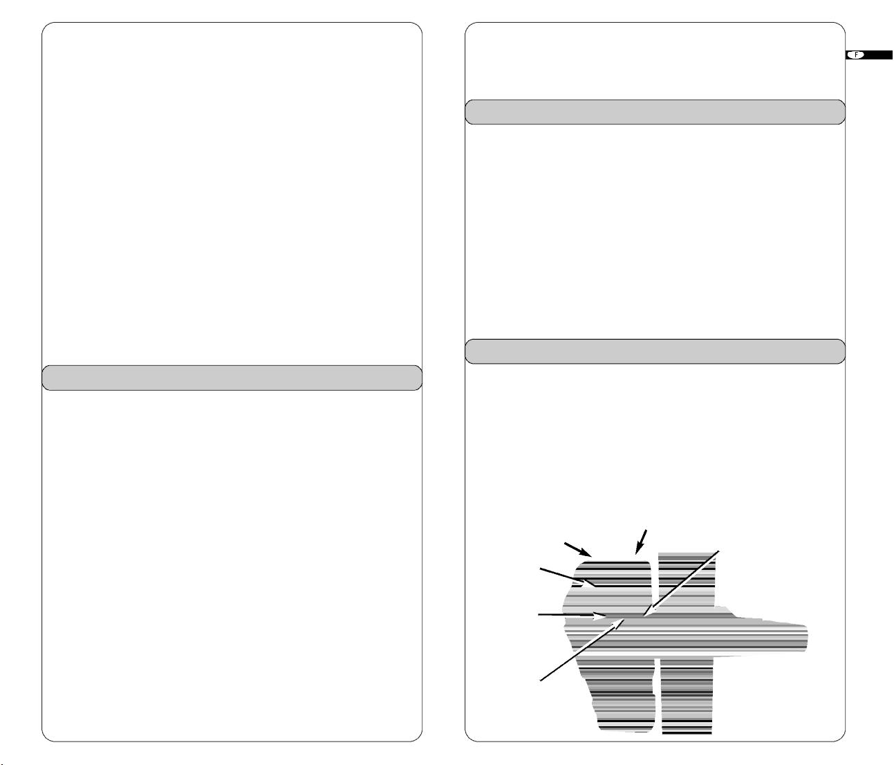
3.1 Horizontal checking and calibration
(X and Y axis)
3.1.1 Horizontal checking
Y axis Z axis
X axis
be calibrated in the X axis. If you have not moved the laser, use the
X marks made in Steps 3 and 4 of 3.1.1 (Horizontal Checking).
5. Mark the spot that's halfway between the two marks.
6. With X 2 facing the marks, bring the laser beam up or down to
the centre mark by using (16) or (17) on the laser keypad or (2) or
(3) on the detector or remote.
7. Next, check Y axis against centre mark. Tu rn the laser 90° so that Y
2 faces the wall. If the beam is not on the centre mark, calibrate Y. If Y
is OK, see «Saving calibration» below.
1. Place the laser on a flat surface 50 or 100 ft. (30m) from a wall.
Position it so that the X 1 is facing the wall.
2. Turn the laser on. After it’s level, stop the rotation so that the beam
is a point.
3. Mark the location of the beam.
4. Rotate the laser 180°. After 90 seconds, mark the location of the
beam near the first mark.
5. Both measurements must be at the same place. At 100 ft., the
marks should be no more than 1/8’’ apart. At 50 ft., the marks
should be no more than 1/16’’ apart. (At 30 meters, no more than
6 mm apart). This is +/- 0.010% leveling accuracy.
6. If the marks are close enough, X axis is within calibration. The
second axis (Y) must then be checked (see Step 7).
If the marks are not close enough, the x axis needs to be re-calibrated
(see instructions below).
7. To check the y axis, turn the laser 90° from Step 4 so that Y 1 is
facing the wall. Repeat the same steps: mark the Y beam, rotate
180°, and mark again. If the marks are more than 1/8’’ apart at
100 ft., Y axis should be re-calibrated.
3.1.2 Horizontal calibration
The laser must be calibrated to bring the beam to the centre of the
two marks (Steps 3-4 in 3.1.1). The calibration is easily done using
the laser keypad, remote control, or detector.
X axis calibration
1 . Tu r n the laser off before switching to calibration mode.
Simultaneously press two laser keys, On/Off and auto/man.
2. After a few seconds, release On/Off key.
3. The X LED indicator (23) will blink, then the y LED (21). Release
the auto/man key.
4. The X LED (23) will blink rapidly, indicating the laser is ready to
Y axis calibration
1. To change to Y axis calibration, press (15) on the laser or (4) on
detector or remote.
The Y LED will blink rapidly, indicating that the laser is ready to be
calibrated in the axis.
2. If you have not moved the laser, use the centre mark from above.
Bring the laser beam up or down to that centre spot by using (16) or
(17) on the laser keypad or (2) or (3) on the detector ro remote.
Saving the calibration
The laser is now calibrated in the X and Y axis. Press (14) on keypad or (5) on detector or remote to save the calibration data. If you
don't wish to save the calibration, press the On/Off key (24) on the
laser.
3.2 Vertical checking and calibration (Z axis)
3.2.1 Vertical checking
1. Place laser in vertical mode, on a flat surface about 10 ft. away
from a plumb line (plumb bob hanging on a string, at least 8 ft.
high). If you need to calibrate, beam will be easier to see in a darkened room.
2. Use the adjustable feet to rough level the laser.
3. Turn the laser on. Stop the rotation so that the beam is a point.
4. Hold the laser head
length of the plumb line by hand. If the beam is slanted, and not
v e r tical like the plumb line, the z axis needs calibration.
3.2.2 Vertical calibration
1 . Tu r n the laser off before switching to calibration mode.
Simultaneously press On/Off and Auto/Man.
and move the beam up and down the entire
10
11
Page 9
2. After a few seconds, release On/Off key.
3. The X LED indicator (23) will blink, then the Y LED (21). Release
the Auto/Man key.
4. The Z LED (19) will blink rapidly, indicating laser is ready to be
calibrated in Z axis.
5. Move the beam until it's vertical and parallel to the plumb line
using (16) or (17) on the laser or (2) or (3) on the detector or remote.
Move the laser slightly so that the beam is over the plumb line for the
final check.
5. Wa r r a n t y
Your SKR301 laser is guaranteed to be free of manufacturing defects
for a period of one year. Any abnormal usage or if the instrument
has been subjected to shock will void this warranty.
Under no circumstances will the liability of the manufacturer exceed
the cost of repairing or replacing the instrument.
Saving the calibration
The laser is now calibrated in Z axis. Press (14) on laser or (5) on
detector or remote to save the calibration data. If you don't wish to
save the calibration, press the On/Off Key on the laser.
4. Care and handling
C A U T I O N : Use of controls or adjustments or perf o r mance of procedures other than those specified herein may result in hazardous
radiation exposure.
SKR301
1. The
care. Avoid shock and vibrations. Always store and transport the
laser and accessories in the carrying case.
2. Although weather resistant, you must always keep your laser and
its accesssories dry and clean after using. This will increase the battery life.
3. Do not store your laser at temperatures below -4°F (-20°C) or
above 176°F (80°C), because the electronic components could be
damaged.
4. Do not store your instrument in its case if the instrument or the case
are wet, to avoid water condensation inside the instrument.
5. To maintain the precision of your laser, check and adjust it
r e g u l a r l y.
6. Keep the lenses of the apertures (2) and (3) clean. Use a soft cloth
and glass cleaner.
7. It is recommended to regularly charge the batteries (for recharge-
able version only). Nevertheless, make sure to charge them only
when they are out of power or becoming so. Recharging batteries
that are still useable will shorten their capacity.
is a precision instrument which must be handled with
Disassembling the instrument by other than qualified technicians will
void this warranty. Specifications subject to change without notice.
6. Accessories
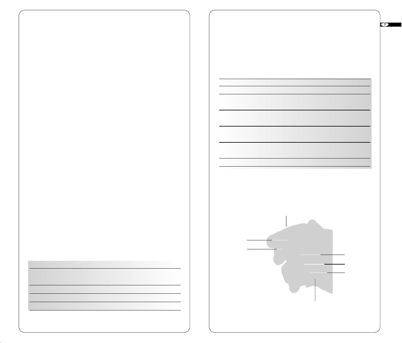
6.1
Combination detector and
laser remote control
For grade rod or handheld applications. Can also be used with
the magnet mount to attach to metal studs for exterior curt a i n
wall alignment or to ceiling grids for acoustical ceiling leveling.
Magnet Window for remote’s
infrared signal
Level vial
LCD
(front)
screen
Detection
window
On-grade
alignment notch
12
13
Page 10
Turn to attach
clamp to
detector
LCD screen
(rear)
Bubble
vial to
plumb rod
• Lower Keypad
Turn to tighten
or remove clamp
from rod
Detector mode
Choice of
sound level
Choice of
accuracy
On/Off
(red keys)
9V battery
compartment
(follow polarity
indications inside)
Use a coin to unscrew
the battery cap
• Upper Keypad
Remote mode Scanning mode
Move square
shot to the left
(vertical mode)
Move square
shot to the right
(vertical mode)
Change to
remote mode
Aim scanning left
Aim scanning right
and are used
for calibration or to
set manual grade
High
Near
grade high
On-grade
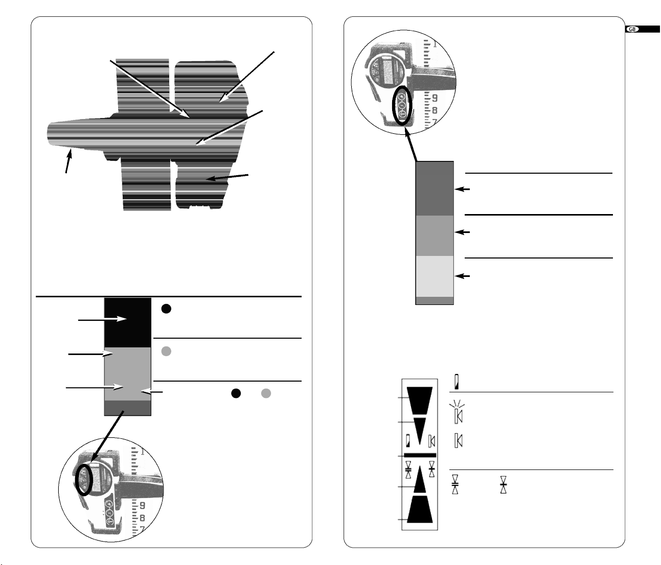
• LCD Display
Remote mode Scanning mode
Increase rotation
speed/move nonrotating point right
Decrease rotation
speed/move nonrotating point left
Start/Stop
scanning mode
Calibration section of manual explains
function of secondary small symbols.
Low battery
Increase
scanning angle
Decrease
scanning angle
Start rotation mode
ATTERY STATUS
B
OUND
S
Blinking: Normal volume
Solid: Loud
No horn: Mute
Near
grade low
Low
Standard
(Default mode)
Fine
A
CCURACY
1514
Page 11
• Detection mode
6.2 Remote control
1. Press the On/Off key to turn on the detector.
2. Press the middle key to select the accuracy (deadband).
3. Press the top key to select the sound level.
4. Turn the detection window towards the laser beam, and move
the detector up or down according to the information given on
the LCD display. There are 5 channels of information, or grade
indicators.
A down arrow indicates you must move the detector down to
reach the laser reference; an up arrow, move it up. When a horizontal line appears on the display, the detector is at the same
level as the laser beam.
5. Press the On/Off key to turn the detector off. It will automatically shut off after 10 minutes if not used (and give a warning
beep).
6. Keep the detection window clean, using a soft cloth and glass
cleaner.
Remote control mode
•
If in detection mode, press On/Off to change to the remote control
functions.
If the detector is not on, press any key (except the On/Off) to use it
as a remote control for the laser.
The remote can be used to stop or start rotation, increase or
decrease rotation speed, and move the beam or square shot. It also
controls scanning and electronic calibration.
The Remote Control stops, starts, or changes direction of laser rotation, and moves the square shot left or right. It also controls scanning and calibration.
An AA alkaline battery (1.5V) ensures 50 hours of continuous use.
To open the battery compartment, push the tab at the top up, in the
direction of the arrow (with a screwdriver).
Beam or chalk line mode S c a n n i n g
1 Scan On / Off
2 S t a r t minimum rotation speed Increase scan length
Move square shot left
3 Move square shot right Decrease scan length
4 Rotation and speed control left Aim scan left
5 Rotation and speed control right Aim scan right
6 AA Battery
To use the remote for calibrating, see pages 10-12.
Remote window
• Specifications
Range* 500 ft. (150 m) in detection mode
100 ft. (30 m) in remote mode
Accuracy* Fine ± <1/16" (1 mm)
Standard ± 1/8” (2.5 mm)
B a t t e r y life 50 hours; 9V alkaline
E n v i r o n m e n t a l Waterproof (IP66+)
Size 6” x 3.25” x 1.5” / 1lb
(15 x 8 x 3.5 cm / 450 g)
* Varies with laser used. Actual accuracy depends on beam diameter and
distance to the laser.
5
4
1
2
3
6 Battery location
1716
Page 12
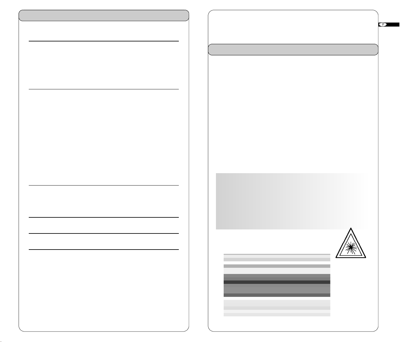
6.3 Mounts
6.3.1 Universal mount
The universal mount can be used as a wall
mount and for vertical setups on a tripod. It
features sturdy, all-metal construction, with a
springactivated mechanism that allows you
to easily change height for quick set-ups.
Also, it has a fine adjustment screw on the
bottom for precise positionings.
• As a wall mount, it can be attached to a grid for
suspended ceiling setup.
• The Mount can also be used on its side and attached
to a tripod (5/8-11) to hold the laser in the vertical position.
6.3.2 Grade mount
Adjustable grade mount is used to lay out inclined planes, such as
cathedral ceilings. Laser must be in manual mode when using the
Grade mount.
6.3.3 Tripods
The laser can be mounted on a 5/8-11 flat head tripod. You can
also use a tripod with an elevating column to adjust the height of
the laser.
SKR301
LASER AUTOMATIQUE
Manuel d’Utilisation
6.4 Other accessories
Universal mount
• Laser-enhancing glasses
improve the visibility of the laser
in bright light conditions.
beam
• CB60 red magnetic target
improves the visibility of the
laser beam in bright conditions.
Quickly attaches to any metallic surf a c e .
18
Page 13
S o m m a i r e
1 . Caracteristiques 2 1
1.1 Description
1.2 Spécifications techniques
1.3 Détails de l’instrument
1.4 Description du clavier
Bien que le SKR301 soit très simple d’utilisation, il vous est vivement
recommandé de lire ce manuel.
1. Caracteristiques
1.1 Description
2. Utilisation 2 3
2.1 Sélecteur “Auto Manuel”
2.2 Sélecteur “TILT”
2.3 Mise en place horizontale
2.4 Mise en place verticale
2.5 Equerrage
2.6 Vitesse de rotation
2.7 Utilisation du trait continu laser
2.8 Utilisation du scanning
2.9 Pente manuelle
3.0 Alimentation
3. Contrôle et réglages 2 7
3.1 Contrôle plan horizontal
3.2 Contrôle plan vertical et calibration
4. Entretien et recommandations 30
5. Garantie 3 1
6. Equipement / Accessoires 3 1
6.1
Cellule de détection
6.2 Télécommande
6.3 Supports
6.4 Autres accessoires
Spécialement conçu pour les entreprises du bâtiment et du second
oeuvre, le SKR301 est généralement utilisé pour les applications suivantes : nivellement, pose et alignement de faux plafonds, de planchers techniques, carrelages, cloisons...
Le niveau laser SKR301 dispose des caractéristiques et
fonctions les plus avancées :
• Calage automatique dans les plans vertical et horizontal,
• 5 modes de visualisation : point laser, ligne,
scanning, rotatif 360° et angle droit,
• Facilité de calibrage
• Équerrage ajustable de droite à gauche
Avertissement :
ou IIIR (version US) respectant les normes de sécurité IEC 285 en
vigueur. Bien que la puissance du rayon n’excède pas 1 mW en
classe II et 2 mW en classe IIIa, il convient de respecter les consignes
de sécurité suivantes :
• Ne pas regarder le faisceau laser de face
• Eviter de placer le niveau laser à hauteur des yeux
Le SKR301 est un produit laser de classe II
2120
Page 14
1.2 Technical Specifications
Distance maximale Plus de 300 mètres de diamètre
d’utilisation recommandée avec la cellule
Précision
Plage de nivellement + / – 8 %
Angle scanning De 3° à 34°
Emission laser Diode laser 635 nm
Energie
Temps de charge 15 hours
Autonomie
Dimensions et poids 15 x 16 x 17 cm - 1.3 kg
Vitesse de rotation 0-90-150-300-450-600 tpm
Étanchéïté Pluie et poussière (IP65)
+/– 0,010 %
+/–10 mm à 100 m
Classe II,
maximum 1 mW (Europe)
Classe IIIR, 635 nm
maximum 2 mW (USA)
2 piles alcalines type LR20 type D
ou batteries rechargeables
40 heures avec batteries
r e c h a r g e a b l e s
160 heures avec piles alcalines
11. Ecrou 5/8 pour fixation sur trépied ou support mural
12. Capuchon pivotant
1.4 Clavier (voir figure 3/4)
14. Contrôle de la vitesse de rotation vers la gauche /
Sauvegarde des données de calibration
15. Contrôle de la vitesse de rotation vers la droite /
Changer l'axe de calibration
16. Déplacement du point d’équerrage et du plan vertical à droite /
Déplacement du point vers le haut
17. Déplacement du point d’équerrage et du plan vertical à gauche /
Déplacement du point vers le bas
18. Fenêtre de réception pour la télécommande
19. Voyant mode manuel / Indicateur de calibration de l’axe Z
20. Manuel / Position automatique
21. Voyant “tilt” / sans “tilt” /Indicateur de calibration de l’axe Y
22. Position “tilt” / sans “tilt”
23. Indicateur batterie faible / Indicateur de calibration de l’axe X
24. Marche / Arrêt
Les fonctions indiquées en italique sont uniquement disponibles en
mode «Réglage».
2. Utilisation
1.3 Détails de l’instrument
1. Tête rotative
2. Emission verticale du rayon laser
3. Emission “Point laser”
4. Emission “Ligne laser”
5. Flèche index 90°
6. Index 90°
7. Pied rabattable pour mode vertical
8. Pied de calage en plan vertical
9. Batterie rechargeable ou alcaline
10. Prise pour alimentation (uniquement sur pack rechargeable)
A la mise en marche du laser, l’appareil effectue un autotest. Le faisceau laser clignote et se met de niveau. Une fois l’auto-nivellement
réalisé, la tête commence sa rotation.
2.1 Sélecteur “Auto/Manuel” (20)
• Auto : Calage automatique
Se met en route dès l’allumage de l’appareil
• Man : Utilisation manuelle
Le laser SKR301 se met en mode automatique par défaut. Une fois
que l’instrument s’est mis à niveau, la tête du laser se met en rotation. Vous pouvez choisir la rotation permanente en utilisant le mode
manuel ; de cette manière, la tête tournera même si le SKR301 n’est
2322
Page 15

pas mis à niveau (recommandé pour les travaux de “rampants” et
plans inclinés).
Pour votre sécurité, le voyant du dessus du bouton Man clignotera
pour indiquer que le laser est en mode manuel.
2.2 Sélecteur “Tilt” (22)
Tilt (contrôle automatique du niveau) : ne se met en route que si la
fonction est sélectionnée (uniquement en mode automatique).
L’action du tilt n’est disponible que 30 secondes après le calage initial de l’appareil. Après ce laps de temps, si le laser est déplacé ou
bousculé, la rotation de la tête s’arrête, le laser s’éteint et le voyant
tilt (22) reste allumé en continu. L’utilisateur doit alors revenir jusqu’à
l’appareil pour l’éteindre, attendre 5 secondes et le rallumer.
L’appareil se remettra de niveau. Bien vérifier la référence de départ.
2.3 Mise en place horizontale
2.5 Equerrage
1. Poser le laser à même le sol et effectuer la mise en place vert i c a l e
(étapes 1 et 2).
2. Arrêter la rotation de la tête en pressant une fois la touche (14) ou (15).
3. Pour positionner le point laser sur le point d’origine de l’angle droit,
• Faire coïncider la flèche (5) située sur la tête et l’index (6) sur
le corps de l’appareil. Vous pouvez aussi utiliser l’index à même
le sol sur le pied rétractable.
• Déplacer le laser de façon à ce que le rayon soit sur le point
de référence au sol tout en conservant la flèche et l’index en
coïncidence.
• Aligner le rayon qui sort du dessus de la tête à l’aide des
touches (16) et (17) sur votre deuxième point de référence
(ce point est à 90° de l’autre rayon qui détermine le plan vert i c a l ) .
• Utiliser les touches (14) ou (15) pour diriger le rayon vers la
droite ou la gauche.
• Faites tourner la tête à la vitesse désirée ou utiliser le trait.
N’oubliez jamais de vérifier en cours de travaux si le laser n’a pas
été déplacé et si vos réglages sont toujours corrects.
1. Le laser SKR301 peut-être posé directement sur le sol ou utilisé sur
son support mural, sur un trépied standard ou trépied à crémaillère.
2. Appuyer sur la touche On/Off (24) pour allumer le SKR301. Le laser
se met en position Automatique et commence son auto-nivellement.
3. Pour sélectionner le mode “manuel”, pressez le bouton (20).
4. Pour sélectionner le mode “tilt”, pressez le bouton (22). Le voyant
se met à clignoter pour confirmer le fonctionnement du mode tilt.
5. Si vous désirez déplacer le point laser vers un endroit précis,
appuyez brièvement sur la touche correspondant au sens de rotation
sélectionné (14) ou (15) jusqu’au positionnement souhaité.
6. Pour régler la vitesse de rotation, maintenez une pression continue
sur la touche (14) ou (15) en fonction de la direction désirée. Pour
stopper la rotation, appuyer brièvement sur la touche inverse.
7. Pour éteindre l’appareil, appuyer sur le bouton marche/arrêt (24).
2.4 Mise en place verticale
Le laser SKR301 peut être posé directement au sol ou sur son support
mural pour une meilleure stabilité.
1. Déplier le pied (7) de l’appareil et le mettre en position verticale.
Puis, ajuster grâce aux pieds réglables (8).
2. Allumer l’appareil et attendre la fin du calage automatique.
2.6 Vitesse de rotation
Votre laser est doté d’une diode laser visible. Toutefois en fonction de la
lumière ambiante il convient de régler la vitesse de rotation grâce aux
boutons (14) et (15). Le laser est plus visible lorsque la vitesse de rotation est faible.
Il est possible d’arrêter la rotation et d’orienter manuellement la tête sur
un point précis, ce qui permet de voir parfaitement le rayon même à
une distance import a n t e .
2.7 Utilisation du trait continu laser
L’option ligne continue vous permet de projeter sur votre
surface de travail un trait laser fixe.
1. Pour utiliser la ligne laser, maintenez le haut de latête immobile
et faites pivoter le “capuchon” (12).
2. Vous obtiendrez alors une ligne laser stable et précise et pourrez
travailler directement sur votre plan de référence.
3. Vous pouvez déplacer la ligne laser en faisant pivoter manuellement la tête de l’appareil ou en utilisant la télécommande infrarouge.
La cellule de réception ne fonctionnera pas si le laser est
en mode trait.
2524
Page 16
2.8 Utilisation du scanning
Le scanning permet de distinguer le faisceau laser à plus longue distance. Pour utiliser le mode scanning, faire pivoter le capuchon de
tête (12) du SKR301 pour le positionner en mode "Point".
Pour activer le mode "scanning", vous pouvez utiliser le clavier du
SKR301 ou encore la télécommande.
1. Pour mettre en fonction le scanning, appuyer simultanément sur
les touches (14) et (17).
2. Utiliser les touches (14) ou (15) pour déplacer le plan défini par
le scanning vers la droite ou la gauche.
3. Utiliser les touches (17) ou (18) pour augmenter ou diminuer l'angle de scanning (3° à 34°) et donc ajuster la largeur du plan défini.
4. Pour stopper le mode scanning et revenir en mode "Point", appuyer simultanément sur les touches (14) et (17).
Pas de possibilité d’équerrage en mode scanning.
Remplacement des piles
1. Lorsque la puissance des piles devient faible, la tête du laser
cesse de tourner et le voyant laser (23) va s’allumer.
2. Remplacer les piles en suivant la même procédure que précédemment.
Changer toujours les deux piles en même temps.
3.0.2 Utilisation de la batterie rechargeable
Première utilisation
Si votre appareil possède l’option batterie rechargeable, vous devez
impérativement effectuer une recharge de 15 heures avant la première utilisation. Pour ce faire :
1. Brancher le chargeur sur une prise électrique 220 ou 110 volts
(selon le chargeur et le pays).
2. Raccorder la prise Jack du chargeur située sous l’appareil (10) à
celle du niveau laser.
3. Respecter le temps de recharge de l’appareil de 15 heures.
2.9 Pente manuelle
1. Allumer l’appareil. Une fois l’auto-nivellement réalisé, appuyer sur la
touche Auto/Man (20). L’indicateur à coté de cette touche va clignoter
(19) ce qui indiquera que vous êtes en position manuelle et que vous
pouvez réaliser une pente sur l’axe X. La rotation de la tête va démarrer.
2. Appuyer sur la touche (17) pour opérer une pente positive en X
et sur la touche (16) pour opérer une pente négative.
3. Pour passer sur l’axe Y, appuyer sur la touche “Tilt” (22). Les deux
indicateurs (19) et
mode manuel et que vous pouvez réaliser une pente sur l’axe Y.
4. Appuyer sur la touche (17) pour opérer une pente positive en Y
et sur la touche (16) pour une pente négative.
(21) vont clignoter, indiquant que vous êtes en
3.0 Alimentation du SKR301
3.0.1 Utilisation des piles alcalines LR20
Installation des piles
1. Pour installer les piles de votre SKR301, dévisser le socle batterie
situé sous l’appareil à l’aide d’une pièce.
2. Sortir le socle de son logement.
3. Placer deux piles alcalines de type LR20 en respectant la polarité
indiquée dans le fond de l’ensemble batterie.
4. Replacer l’ensemble batterie dans l’appareil et revisser. Votre
SKR301 est prêt à l’emploi.
Always
recycle batteries
Recharges ultérieures
Quand recharger la batterie de votre SKR301. Vous pouvez le
charger pendant la nuit ou sur chantier si vous avez de l’électricité.
L’appareil se recharge tout en fonctionnant. Pour une durée de vie
plus longue (batteries cadium-nickel) il est recommandé de les
recharger après qu’elles soient totalement déchargées.
Eviter de recharger pendant plus de 20 heures en continu. Les batteries et le chargeur supportant mal l’humidité, il est conseillé de
procéder à ces opérations dans un endroit sec.
Ne pas jeter les piles aux
ordures ou dans des
poubelles similaires
3. Contrôles et réglages
CE CHAPITRE EST TRES IMPORTANT : vous avez ci-dessous
quelques indications pour le contrôle et le réglage de votre
SKR301. N’oubliez pas que le laser est un instrument de mesure
et qu’il est important d’effectuer comme tout professionnel les contrôles nécessaires. La précision de votre travail est sous votre seule
responsabilité. Vous devez vérifier régulièrement votre laser et ce,
p a r ticulièrement avant tous travaux importants. Mais il est toutefois important d’effectuer des contrôles fréquents de votre
appareil. Voici quelques méthodes simples de contrôle et de
réglage que vous pouvez faire sur votre chantier.
2726
Page 17
3.1 Contrôle plan horizonatal et calibration
3.1.1 Contrôle plan horizontal
1. Placer le laser sur une sur-
face plane à environ 30 m
d’un plan vertical (mur,
porte...).
2. Allumer le laser en mode
automatique. Stopper la rotation de la tête.
3. Repérer et noter l’impact du laser.
4. Faire pivoter le laser de 180° (200 gr). Repérer et noter l’impact
du laser (après 90 secondes)
5. Les deux mesures doivent être à la même hauteur (tolérance max.
0.010%). Si la distance entre le mur et le laser est de 30 mètres, la
tolérance maximum sera de 6 mm.
6. Si les marques sont dans la tolérance, l’axe X est calibré et l’axe
Y peut maintenant être contrôlé (cf. point 7). Sinon l’axe X doit être
re-calibré (selon point 3.1.2)
7. Pour contrôler l’axe Y, tourner le laser de 90° (à partir de l’étape
4) de façon à ce que l’axe Y1 soit face au mur. Répéter les mêmes
opérations : marquer l’impact Y du laser, faire pivoter le laser de
180°, marquer à nouveau l’impact du laser. Si les marques sont dans
la tolérance, l’axe Y est calibré. Sinon, l’axe Y doit être re-calibré.
Votre niveau laser SKR301 doit être réglé afin que le point laser se situe
au centre des marques définies lors des paragraphes précédents.
Le réglage de votre appareil peut être réalisé facilement en utilisant
le clavier du SKR301 ou la télécommande.
3.1.2 Calibration plan horizontal
Y axe Z axe
X axe
i n f o rmer que votre SKR301 est désormais prêt à être ajuster sur l'axe X.
Si vous n'avez pas déplacé le laser, utiliser les marques que vous
avez précédemment définies lors des étapes 3 et 4 du paragraphe
3.1.1 ( contrôle horizontal ).
5. Notez alors le point situé au centre des deux marques.
6. Avec l’axe X2 faisant face aux marques, faites monter ou descen-
dre le point laser à l’aide des touches (16) et (17) du clavier, (2) ou
(3) de la LDR180 ou de la télécommande pour positionner le point
sur la marque définie à l’étape 5.
7. Puis, vérifier l’axe Y avec la marque centrale. Faire pivoter le
laser de 90° pour que l’axe Y2 soit face au mur. Si le laser n’est pas
sur le point central, il faut le calibrer. S’il y est, voir le paragraphe
ci-dessous “sauvegarde de la calibration”.
Calibration en Y
1. Pour passer au réglage de l'axe Y, appuyer sur la touche (15) du
clavier, (4) de la télécommande ou (11) de la LDR180. L'indicateur
de calibration Y clignotera alors rapidement, vous indiquant que
votre SKR301 est prêt à être régler sur l'axe Y.
2. Faites monter ou descendre le point laser à l’aide des touches
(16) et (17) du clavier, (2) ou (3) de la LDR180 ou de la télécommande pour positionner le point sur la marque définie à l’étape 5.
Sauvegarde de la calibration
Votre niveau laser SKR301 est désormais réglé sur les axes X et Y.
Appuyer sur la touche (14) du clavier, (10) de la LDR180 ou (5) de
la télécommande afin de sauvegarder les données du réglage.
Si vous ne souhaitez pas sauver les données, appuyez simplement
sur la touche Marche /Arrêt (24) du laser.
The laser must be calibrated to bring the beam to the centre of the
two marks (Steps 3-4 in 3.1.1). The calibration is easily done using
the laser keypad, remote control, or detector
Calibration en X
1. Eteindre le laser. Appuyer simultanément sur les touches (20) et
(24) du clavier afin de mettre en fonction le mode "Réglage".
2. Après quelques secondes, relachez la touche Marche/Arrêt (24).
3. L'indicateur de calibration X clignotera puis l'indicateur de
calibration Y. Relachez alors la touche Auto/Man (20).
4. L'indicateur de calibration X clignotera rapidement pour vous
.
3.2 Contrôle plan vertical et calibration
3.2.1 Contrôle plan vertical
1. Placer votre niveau laser SKR301 sur une surface plane à environ
3 mètres d'un fil à plomb. S'il est nécessaire de régler votre appareil,
il sera préférable de le faire dans une pièce peu lumineuse.
2. Utilisez le pied ajustable et les molettes (8) pour positionner le laser.
3. Mettre la laser en marche en appuyant sur la touche (24) Stopper
la rotation de la tête.
4. Tenez la tête du laser et déplacer le point le long du fil à plomb.
Si le point dévie du fil à plomb, l'axe Z doit être réglé.
2928
Page 18
3.2.2 Calibration plan vertical
1. Eteindre le laser. Appuyer ensuite simultanément sur les touches
(20) et (24).
2. Après quelques secondes, relachez la touche(24).
3. L'indicateur de calibration X clignotera puis l'indicateur Y.
Relachez alors (20).
4. L'indicateur de calibration Z clignotera rapidement, indiquant que
votre SKR301 est prêt à être réglé sur l'axe Z.
5. Utilisez les touches (16) et (17) du clavier, (2) ou (3) de la télécommande afin de déplacer le point jusqu'à ce qu'il soit parfaitement parallèle au fil à plomb.
Déplacez le laser jusqu'à ce que le point ait dépassé le fil à plomb
afin de réaliser un contrôle final.
Sauvegarder la calibration
Le laser est désormais calibré. Appuyer sur la touche (14) du clavier,
ou (5) de la télécommande pour sauvegarder les données. Si vous
ne le souhaitez pas, appuyez sur la touche (24).
4. Entretien / Recommandations
AVERTISSEMENT : Procéder à des contrôles ou des réglages
autres que ceux indiqués ou conseillés dans ce manuel peut occasionner une exposition dangereuse à des radiations.
1. Le SKR301 est un instrument de précision qui doit être manipulé
avec précautions. Evitez le plus possible les chocs et vibrations et
manipulez-le avec soin. Le SKR301 est à transporter dans son
coffret, ainsi que ses accessoires.
2. Bien qu’étanche à la pluie et à la poussière, s’il a été mouillé,
prenez soin d’essuyer votre laser et ses accessoires après usage.
Conservez-les dans un endroit sec. Vous augmenterez ainsi la durée
de vie des batteries.
3. Ne rangez pas votre laser dans un local d’une température
inférieure à -20°C ou supérieure à 80°C, vous risqueriez d’endommager les composants électroniques.
4. Ne rangez pas l
l’eau dans le coffret pour éviter tout effet de condensation ou de buée.
5. Pour maintenir la précision de votre laser, vérifiez-le régulièrement.
6. Maintenez propres les lentilles (2.3) correspondant à la sortie du
laser. Les nettoyer avec un chiffon doux et un produit pour les vitres.
e laser dans son coffret s’il est mouillé ou s’il y a de
7. Il est recommandé de recharger régulièrement la batterie du laser
en respectant les temps de charge.
5. Garantie
Votre laser SKR301 est garanti 1 an contre tout défaut de fabrication. Les chocs, chutes et autres utilisations anormales annuleraient
cette garantie. Les utilisateurs sont tenus de vérifier leur instrument
régulièrement. En cas d’erreur, les réglages peuvent être faits sous
garantie mais en aucun cas la garantie ne peut dépasser le coût de
la réparation voire au maximum le remplacement de l’appareil.
Tout démontage de l’appareil effectué par des techniciens non habilités annule la garantie.
Les spécifications de cet instrument peuvent être modifiées à tout
moment et peuvent différer du catalogue et du mode d’emploi.
6. Accessoires
6.1
Cellule de détection/télécommande
Elle convient pour les mires graduées ou d'autres applications
manuelles. Grâce à son support magnétique, elle peut être aussi
utilisée pour des alignements de murs en extérieur ou pour ajuster
en plafond les grilles acoustiques.
Fenêtre pour le signal infrarouge
Aimant
Niveau
à bulle
Ecran
(face)
LCD
Fênetre
de détection
de la télécommande
Repère
d’alignement
3130
Page 19

Bouton de fixation
de la bride à la
cellule
Bouton de
fixation de la
bride à la mire
Mode détection
Choix du
niveau sonore
Choix du niveau
de
la précision
Marche / Arrêt
(merci de respecter les
Utiliser une pièce de monnai pour
polarités à l’intérieur)
soulever le capot de la pile
• Partie haute du clavier
Mode
télécommande
Déplace le point
vers la gauche
(mode vertical)
Déplace le laser
vers la droite
(mode vertical)
Bascule en mode
télécommande
Mode scanning
Dirige le scan vers
la gauche
Dirige le scan vers
la droite
et sont
réservés au calibrage
ou au réglage manuell
Ecran LCD
(dos)
Niveau à
bulle pour
la mire
Compartiment
pour la
batterie 9V
Haut
I n t e r mediaire
h a u t
Sur le
laser
• Ecran LCD
• Partie inferieure du clavier
Mode
télécommande Mode scanning
Augmente la vitesse
de rotation /
déplace le point
vers la droite
Diminue la vitesse
de rotation /
déplace le point
vers la gauche
Marche/Arrêt du
mode scanning
La partie calibrage du manuel décrit les
fonctions des symboles inscrits en petits sur
les touches
.
Batterie faible
Augmente l'angle de
scanning
Diminue l'angle de
scanning
Démarre le mode
rotatif
E
TAT
DE LA BATTERIE
ON
S
Clignote : volume normal
Permanent : volume fort
Pas de signal : muet
I n t e r m e d i a i r e
bas
Bas
Standard
(Par défaut)
Fin
P
RÉCISION
3332
Page 20
• Utiliser la cellule
6.2 Télécommande
1 . Presser le bouton On/Off pour mettre en marche la cellule.
2 . Presser le bouton central pour choisir le mode de précision.
3 . Presser le bouton du haut pour choisir le niveau de son souhaité.
4 . Faire pivoter la fenêtre de détection vers le rayon laser, et
déplacer la cellule vers le haut ou le bas suivant l’indication
fournie sur l’écran LCD.
Il existe 5 niveaux d’information.
Une flèche vers le bas indique que la cellule doit être déplacée
vers le bas pour atteindre le niveau de référence du laser.
Une flèche vers le haut sur l’écran, indique qu’il faut monter la
cellule au contraire. Lorsqu’une ligne horizontale apparaît sur
l’écran, cela signifie que la cellule est au niveau du rayon laser.
5 . Presser la touche On/Off pour éteindre la cellule. Elle
s’éteindra automatiquement après 10 minutes de non utilisation
(un signal sonore vous l’indiquera).
Mode télécommande
•
Si la cellule est en mode détection, appuyer sur la touche On/Off pour
basculer en mode télécommande.
Ce mode permet d'arrêter ou de démarrer la rotation, l'augmenter ou la
d i m i n u e r, et déplacer le laser ou le point. Il perme
t aussi de contrôler le
scanning et le calibrage électronique.
• Caractéristiques techniques
Distance maximale d’utilisation* 150 m
Précision* Fin ± 1 mm
Standard ± 2.5 mm
Autonomie Batterie 50 heures (9 V Alcaline)
Environnement Etanche ( IP 66+ )
Dimensions 15 x 8 x 3.5 cm /
*Dépend du laser utilisé. La précision varie en fonction du diamètre du
rayon et de la distance jusqu’au laser.
450 g
Elle est utilisable jusqu’à une distance de 30 mètres. Elle perm e t
d’actionner et d’arrêter la rotation de la tête du laser et de déplacer le point, la ligne ou le scanning jusqu’à un po int désiré (dans le
mode horizontal ou vert i c a l ) .
Laser en mode point/Ligne S c a n n i n g
1 Mise en marche/Arrêt
2 Démarrer rotation mini. à gauche Augmentation taille du
Déplacer plan vertical à gauche s c a n n i n g
3 Démarrer rotation mini. à droite Réduction taille du
Déplacer plan vertical à droite s c a n n i n g
4 Rotation et contrôle de la vitesse Orientation du scanning
de rotation vers la gauche vers la gauche
5 Rotation et contrôle de la vitesse Orientation du scanning
de rotation vers la droite vers la droite
6 Emplacement pile
Pour utiliser la cellule de détection en mode calibration, se report e r
aux pages 28-30
Fênetre de télécommande
5
4
1
2
3
6 Emplacement pile
3534
Page 21
6.3 Supports
6.3.1. Support universel
Le support a été spécialement conçu pour
la position horizontale (et la position vert icale avec équerrage sur trépied).
Entièrement métallique, et très résistant, sa
vis à ressort permet un réglage rapide de
la hauteur.
• En support mural, il se fixe sur les
c o r nières pour effectuer la pose de
faux plafonds. Le réglage fin en hau
teur permet un positionnement précis, la vis pointeau du bas
s e r vant d’appui sur le mur et de préréglage du niveau.
• En support pour plans verticaux et équerres, il se visse
directement sur un trépied.Also, it has a fine adjustment
screw on the bottom for precise positionings.
6.3.2. Support incliné
P e r met de mettre le laser suivant un plan incliné. Le laser doit être
en utilisation manuelle.
6.3.3. Trépieds
SKR301
LASER AUTOMATICO
Instrucciones de uso
Des trépieds plats ou à dôme sont conseillés. Il est également possible de fixer le SKR301 sur un trépied à crémaillère, ce qui assure
un réglage à
la hauteur désirée.
6.4 Autres accessoires
• Lunettes pour laser : Elles
améliorent trés sensiblement la visibilité du rayon laser dans les zones à
luminosité import a n t e .
• Cible CB 60: Transparente et
de couleur rouge, la CB 60 est plus
p a r ticulièrement utilisée en intérieur
pour mieux visualiser ou repérer le
passage du rayon laser.
Elle se fixe magnétiquement.
36
Page 22
Tabla de contenidos
1.
I n f o rmación general
1.1 Descripción
1.2 Especificaciones técnicas
1.3 Descripción de las vistas, general
1.4 Te c l a d o
2.
Cómo utilizar el nivel láser S K R 3 0 1
2.1 Selector automático/manual (20)
2.2 Tecla de inclinación “tilt” (22)
2.3 Instalación horizontal
2.4 Instalación vert i c a l
2.5 Escuadrado
2.6 Velocidad de rotación
2.7 Utilización del modo línea
2.8 Utilización del modo exploración
2.9 Inclinación manual
3.0
Alimentación eléctrica
3.
Verificación y ajuste del nivel láser S K R 3 0 1
3.1 Verificación y calibración horizontales (ejes X e Y)
3.2 Verificación y calibración verticales (eje Z)
4.
Cuidado y manejo
5.
G a r a n t í a
6.
A c c e s s o r i o s
6.1 Detector
6.2 Mando a distancia
6.3 Soport e s
6.4 Otros accessorios
39
41
46
49
49
50
Aunque el nivel láser SKR301 es muy fácil de usar, recomendamos
leer este manual antes de ponerlo en funcionamiento
1. Información general
1.1 Descripción
El SKR301 es un nivel láser visible automático que se puede utilizar
para nivelado, alineación vertical, para aplomar y para escuadrar.
Entre sus aplicaciones se incluye la instalación de falsos techos, suelos técnicos, particiones y una amplia gama de labores de alineación en exteriores.
El láser SKR301 está dotado de las siguientes características avanzadas:
• Nivelado automático tanto en modo horizontal como vertical.
• Gama de haces: funciones de rotación, exploración, línea,
punto o escuadrado continuo.
• Sencilla calibración electrónica.
• Haz en perpendicular para escuadrado ajustable a izquierda
y derecha.
Precaución:
para EE.UU.) y está fabricado de acuerdo con las normas internacionales de seguridad IEC 285. Aunque la potencia de emisión del
rayo no supera 1 mW en la Clase II y 2 mW en la Clase IIIa, se
recomienda adoptar las siguientes precauciones:
No mire directamente al haz de láser
El nivel láser SKR301 es de Clase II o IIIR (versión
3938
Page 23
1.2 Especificaciones técnicas
1.4 Descripción del teclado
Distancia máxima de 300 m con el detector
utilización recomendada
Precisión de nivelado
Rango de nivelado + / – 8 %
Ángulo de exploración De 3° a 34°
Diodo láser De 635 nm máximo
Alimentación eléctrica
Tiempo de carga 15 horas
Autonomía
Dimensiones 15 x 16 x 17 cm
Velocidad de rotación 0-90-150-300-450-600 rpm
Estanqueidad Lluvia y polvo (IP65)
0,010 %
(+/–10 mm a 100 m)
Versión para Europa: 1 mW
Clase II
Versión para EE.UU. 2 mW, Clase IIIR
2 pilas alcalinas (LR20 o D)
o baterías recargables
40 horas con baterías recargables
160 horas con pilas alcalinas
1.3 kg
14. Control de rotación del láser a la izquierda +
control de velocidad / Grabar datos de calibración
15. Control de rotación del láser a la derecha +
control de velocidad / Cambiar eje de calibración
16. Movimiento del haz perpendicular a la derecha/
Mover haz hacia abajo
17. Movimiento del haz perpendicular a la izquierda /
Mover haz hacia arriba
18. Ventana de recepción del mando a distancia
19. Indicador luminoso de modo manual /
Indicador de calibración en el eje Z
20. Modo automático/manual
21. Indicador luminoso de inclinación (tilt) /
Indicador de calibración en el eje Y
22. Advertencia de inclinación (tilt)
23. Indicador luminoso de pila baja /
Indicador de calibración en el eje X
24. Encendido / Apagado
Las descripciones en cursiva corresponden a indicaciones y teclas
utilizadas en el modo de calibración.
2. Cómo utilizar el nivel láser S K R 3 0 1
1.3 Descripción del láser
1. 1 Cabezal giratorio
2. Abertura del haz vertical para escuadrado o aplomo
3. Abertura del haz principal
4. Abertura del láser para modo línea
5. Flecha
6. Marca de 90º (una de cuatro)
7. Pie plegable para instalación vertical
8. Pies regulables para instalación vertical
9. Pilas
10. Enchufe del cargador de pilas
11. Soporte 5/8” – 11
12. Tapa superior
En la portada interior se encuentra una descripción general de las
funciones del nivel láser y de su teclado.
Cuando se enciende el nivel láser, éste procede a efectuar una prueba automática. El haz parpadea mientras el nivel láser se está
autonivelando. Una vez nivelado, el cabezal comienza a girar.
2.1 Selector automático/manual (20)
• Auto: Nivelado automático. Es el modo de funcionamiento
predeterminado cuando se enciende el nivel.
• Man: Uso manual
El nivel láser SKR301 se encuentra siempre en el modo de nivelado
automático (auto) cuando se enciende. Una vez que el instrumento
se ha nivelado, el cabezal del láser comienza a girar.
4140
Page 24

Puede seleccionar una rotación continua de forma manual. De esta
manera el haz gira incluso aunque el instrumento no se encuentre nivelado, lo cual es necesario cuando se trabaja sobre planos inclinados.
Por razones de seguridad el indicador luminoso de color rojo situa
do sobre el botón de modo Auto/Man indicará al usuario que el
láser se encuentra en modo manual.
2.2 tecla de inclinación “tilt” (22)
Inclinación: Modo de advertencia de Tilt. Esta función sólo
se encuentra activa si se ha seleccionado. La función Tilt de inclinación se conoce también como advertencia de H.I. (height of instrument, altura del instrumento). Su objeto es detener automáticamente
el láser en caso de que éste se golpee o mueva, para evitar la toma
de medidas imprecisas. Utilice esta función sólo en el modo
automático, nunca en el manual.
Pulse la tecla Tilt (22) después de encender el instrumento. La función
de advertencia de inclinación se pone en funcionamiento 30 segundos después de que el instrumento se haya nivelado automáticamente.
El indicador luminoso rojo situado sobre la tecla Tilt parpadea cuando este modo está activado.
Si el nivel láser sufre cualquier perturbación, el cabezal detendrá su
giro y la luz roja se mantendrá continuamente encendida. Apague
el nivel láser, espere 5 segundos y enciéndalo de nuevo (verifique
que el haz se encuentra en su punto de referencia original).
2.3 Instalación horizontal
1. El nivel láser SKR301 se puede colocar directamente sobre el
suelo, en montaje mural o sobre un trípode estándar (5/8” – 11).
2. Pulse la tecla de encendido/apagado (24) para encender el nivel
láser. El instrumento comenzará su nivelado de forma automática.
3. Para seleccionar el modo manual, pulse la tecla (20).
4. Para seleccionar el modo TILT, pulse la tecla (22). Esta función se
activa 30 segundos después de que el nivel láser se haya nivelado.
5. Si desea mover el haz de láser hacia un punto en concreto, pulse
brevemente la tecla (14) o la (15).
6. Para ajustar la velocidad de rotación, mantenga pulsada la tecla
(14) o la (15) en función de la dirección deseada. Para detener el
giro, pulse la tecla opuesta una vez.
7. Para apagar el nivel láser, pulse la tecla (24).
2.4 Instalación vertical
Para el montaje en esta posición no se necesita accesorio alguno.
El SKR301 se puede colocar directamente sobre el suelo.
No obstante se puede ubicar de forma más segura sobre un soporte.
1. Recoja hacia arriba el pie plegable (7). Coloque el instrumento
en posición vertical, sobre su pie. Utilice los pies regulables (8) para
nivelar el nivel láser de forma aproximada.
2. Encienda el instrumento. Una vez nivelado el instrumento, el
cabezal del láser comienza a girar.
2.5 Escuadrado
1. Coloque el nivel láser sobre el suelo y repita los pasos 1 y 2
descritos para la instalación vert i c a l .
2. Detenga el giro del cabezal pulsando la tecla (14) o la (15).
3. Para colocar el plano vertical de rotación perpendicular a la línea
de referencia:
• Alinee la flecha (5) situada bajo al abertura del haz con el
índice (6) situado encima del pie plegable (hay asimismo una
marca sobre el pie).
• Mueva el nivel láser de manera que el haz se coloque sobre
el punto de referencia del suelo, al tiempo que mantiene
alineados la flecha y el índice mencionados.
• Alinee el haz de la parte superior del cabezal con su
segundo punto de referencia mediante la tecla (16) o la (17),
con el detector o con el mando a distancia (este haz forma un
ángulo de 90° con el haz de plano vertical).
• Comience a girar el cabezal mediante la tecla (14) o la (15)
para variar la velocidad o para utilizar el modo línea.
Cuando utilice el nivel láser es importante verificar que no se ha
movido y que su colocación continúa siendo precisa.
2.6 Velocidad de rotación
Su nivel láser está equipado con un diodo láser de luz visible. Podría
ser necesario ajustar la velocidad de rotación en función de las condiciones de luz ambiental, mediante las teclas (14) y (15). El haz de láser
se ve mejor a baja velocidad. Es posible detener la rotación y apuntar
el haz manualmente para visualizar el haz en distancias grandes.
4342
Page 25
2.7 utilización del modo línea
Ideal para visualización a distancias cortas. Para utilizar el
modo línea del láser, sujete el cabezal y haga girar la tapa superior (12) de manera que el haz salga por la abertura correspondiente
al modo línea (4). De esta manera se obtiene una línea de láser precisa y estable para trabajar directamente sobre su plano de referencia. Esta línea se puede desplazar girando manualmente el
cabezal o mediante el mando a distancia.
El detector LDR180 no se puede utilizar con el modo línea.
2.8 Utilización del modo exploración
Este modo le permite ver mejor el haz cuando el nivel
láser se encuentra lejos. Para utilizar el modo exploración,
encienda el nivel láser. El láser debe estar ajustado en modo
“punto”. Si está en modo línea, sujete el cabezal y haga girar la
tapa superior (12) de manera que el haz salga por la abertura del
modo punto (3).
Para ajustar el nivel láser en modo exploración, utilice el teclado
(véase a continuación), el detector o el mando a distancia.
1. Para proceder a la exploración pulse simultáneamente las teclas
(14) y (17). El haz parpadeará hasta que el instrumento se haya
nivelado y una vez hecho esto, comenzará la exploración.
2. Use la tecla (14) o la (15) para orientar la exploración.
3. Utilice las dos teclas inferiores para ajustar la amplitud de la
exploración. Use la tecla (17) para aumentarla y la tecla (18) para
disminuirla (entre 3° y 34°).
4. Para detener la exploración pulse simultáneamente de nuevo las
teclas (14) y (17). El haz de escuadrado no se puede mover a
izquierda ni derecha durante la exploración, para ello el nivel láser
debe estar en modo punto o línea.
2.9 Inclinación manual
1. Después de encender el nivel láser y dejar que se nivele automáti-
camente, pulse la tecla Auto/Man (20). El indicador LED situado
junto a ella (19) parpadeará, indicando que el nivel está en modo
manual y que puede ajustar la inclinación sobre el eje X. A continuación el cabezal comenzará a girar.
2. Pulse la tecla (17) para ajustar una inclinación positiva respecto
al eje X o la tecla (16) para una inclinación negativa.
3. Para cambiar al eje Y, pulse la tecla Tilt (22). Ambos indicadores
LED (19) y (21) parpadearán, indicando que el nivel está en modo
manual y que puede ajustar la inclinación sobre el eje Y.
4. Pulse la tecla (17) para ajustar una inclinación positiva respecto
al eje Y o la tecla (16) para una inclinación negativa.
3.0 Alimentación eléctrica
3.0.1 Instalación de las pilas alcalinas
1. Para instalar las pilas alcalinas en su nivel láser SKR301 desen-
rosque la tapa situada en la parte inferior del instrumento.
2. Retire el soporte con las pilas.
3. Introduzca dos pilas alcalinas (D o LR20) en el soporte, haciendo
coincidir la polaridad de forma correcta (“+” o “–”) tal como se
indica en la parte inferior del soport e .
4. Vuelva a colocar el soporte de las pilas en su sitio y apriete el torn i l-
lo. Su nivel láser SKR301 se encuentra ahora dispuesto para su uso.
Cambio de las pilas
1. Cuando las pilas están bajas el cabezal láser detiene su giro y
se enciende el indicador luminoso de la pila (23).
2. Sustituya ambas pilas al mismo tiempo.
3.0.2 Utilización de baterías recargables
Primer uso
Si su nivel láser SKR301 dispone de batería recargable, deberá
recargarla durante 15 horas antes de su primer uso.
1. Introduzca el enchufe del cargador en la toma situada en la
batería (10).
2. Enchufe el cargador a un enchufe de la red (110 o 220 voltios,
en función del cargador y del país).
3. Cargue la batería durante 15 horas.
Recicle siempre
las
pilas.
Recargas posteriores
El nivel láser SKR301 se puede cargar durante su funcionamiento. Si
dispone de corriente eléctrica en el emplazamiento de la obra,
se
enchufe el cargador y continúe con su tarea. También puede retirar
la batería para cargarla y colocar pilas alcalinas en su lugar para
poder continuar trabajando.
Para conseguir una duración óptima de la batería se recomienda
cargarla únicamente cuando se haya descargado por completo.
Para garantizar la duración de la batería no la mantenga más de
20 horas cargando.
El cargador y la batería se pueden estropear si están húmedos.
Guarde y cargue siempre el instrumento en un sitio seco y a cubiert o .
No tire las pilas a la
basura normal.
4544
Page 26

3. Verificación y ajuste del nivel láser S K R 3 0 1
3.1.2 Calibración horizontal
ESTE CAPÍTULO ES MUY IMPORTA N T E : : A continuación se
facilitan unas sencillas instrucciones para verificar la calibración
de su nivel láser SKR301.
Recuerde que el nivel láser es un instrumento de precisión y que es
importante mantenerlo calibrado y en buenas condiciones. La precisión de su trabajo es sólo responsabilidad suya y deberá comprobar el instrumento con regularidad, en especial antes de realizar tareas importantes. Antes de efectuar ninguna calibración asegúrese
de que el nivel láser está en modo punto al detener su rotación.
A continuación se facilitan las indicaciones para verificar la cali-
bración en cada eje. Si el nivel láser necesitase ser calibrado,
siga dichas instrucciones o llévelo a un centro de asistencia
3.1 Verificación y calibración horizontales
(ejes X e Y)
3.1.1 Verificación horizontal
1. Coloque el nivel láser sobre
una superficie plana a una distancia de entre 15 y 30 m de
una pared. Colóquelo de forma
que el X1 mire hacia la pared.
2. Encienda el instrumento. Una
vez nivelado, detenga su rotación de mane
3. Marque la posición del haz.
4. Gire el láser 180°. Después de que transcurran 90 segundos,
vuelva a girar el láser 180º y marque la posición del haz junto a la
primera marca.
5. Ambas marcas deberían estar en el mismo sitio. A 30 m las marcas no deberían distar más de 6 mm entre sí. A 15 m las marcas no
deberían distar más de 3 mm entre sí. Si esto se cumple, la precisión
del nivelado es de +/- 0,010%.
6. Si las marcas están dentro de este margen, el eje X está calibra-
do. A continuación se debe verificar el eje Y (véase paso 7). Si las
marcas no están suficientemente cerca, el eje x necesita ser recali-
brado (consúltense las instrucciones que se ofrecen a continuación).
7. Para verificar el eje Y, gire el láser 90º a partir del paso 4, de
manera que Y1 quede frente a la pared. Repita los mismos pasos:
marque la posición del haz Y, gire el instrumento 180º, vuélvalo a
girar y marque de nuevo. Si las marcas se encuentran alejadas una
de la otra más de 6 mm a 30 m, el eje y necesita ser recalibrado.
eje Y eje Z
eje
X
ra que el haz sea un punto.
El nivel láser se debe calibrar para situar el haz en el centro de las
dos marcas hechas anteriormente (pasos 3 a 4 del apartado 3.1.1).
La calibración se efectúa fácilmente con el teclado del instrumento,
el mando a distancia o el detector.
Calibración del eje X
1. Apague el nivel láser antes de ajustarlo en modo calibración. Pulse
simultáneamente las dos teclas Encendido/Apagado y Auto/Man.
2. Deje transcurrir unos pocos segundos y suelte la tecla de
Encendido/Apagado.
3. El indicador LED X (23) parpadeará y a continuación lo hará el
indicador LED Y (21). Suelte la tecla Auto/Man.
4. El indicador LED X (23) parpadeará rápidamente, lo que indica
que el nivel láser está listo para ser calibrado en el eje X. Si no ha
movido el instrumento puede utilizar las marcas x que ha realizado
en los pasos 3 y 4 del apartado 3.1.1 (Verificación horizontal).
5. Marque la posición que se encuentra a medio camino de ambas marcas.
6. Con X2 mirando a las marcas, ajuste el haz de láser para que
coincida con la marca central mediante la tecla (16) o la (17) del
teclado del instrumento o mediante la (2) o la (3) del detector o del
mando a distancia.
7. A continuación verifique el eje Y frente a la marca central. Haga girar
90° el instrumento de manera que Y2 mire
cide con la marca central, calibre el eje Y. En caso de que sí coincida,
consulte abajo el apartado de “Grabación de la calibración”.
Calibración del eje Y
1. Para pasar a la calibración del eje Y, pulse la tecla (15) del instrumento o la (4) del detector o del mando a distancia. El indicador LED
Y parpadeará rápidamente, lo que indica que el nivel láser está listo
para ser calibrado en el eje Y.
2. Si no ha movido el instrumento, utilice la marca central realizada
a n t e r i o rme nte. Ajuste el haz de láser para que coincida con dicha
posición central mediante la tecla (16) o la (17) del teclado del instrumento o mediante la (2) o la (3) del detector o del mando a distancia.
Grabación de la calibración
Ahora el nivel láser se encuentra calibrado en los ejes X e Y.
Pulse la tecla (14) del teclado o la (5) del detector o del mando a distancia para grabar los datos de calibración. Si no desea grabar la
ibración, pulse la tecla de Encendido/apagado (24) del nivel láser.
a la pared. Si el haz no coin-
cal-
4746
Page 27

3.2 Verificación y calibración verticales (eje Z)
4. Cuidado y manejo
3.2.1 Verificación vertical
1. Ajuste el nivel láser en modo vertical, sobre una superficie plana
a una distancia de alrededor de 3 m a una línea a plomo (con una
plomada convencional con un hilo de al menos 2,4 m). Si tuviera
necesidad de calibrar el instrumento, el haz se ve mejor en una
estancia oscura.
2. Utilice los pies regulables para nivelar el nivel láser de forma
aproximada.
3. Encienda el instrumento. Detenga la rotación de forma que el haz
sea un punto.
4. Sujete el cabezal del láser y mueva el haz hacia arriba y hacia
abajo por toda la longitud del hilo de plomada de forma manual. Si
el haz está inclinado, desviado de la vertical del hilo de la plomada, significa que el eje z necesita ser calibrado.
3.2.2 Calibración vertical
1. Apague el nivel láser antes de ajustarlo en modo calibración.
Pulse simultáneamente las teclas Encendido/Apagado y Auto/Man.
2. Deje transcurrir unos pocos segundos y suelte la tecla de
Encendido/Apagado.
3. El indicador LED X (23) parpadeará y a continuación lo hará el
indicador LED Y (21). Suelte la tecla Auto/Man.
4. El indicador LED Z (19) parpadeará rápidamente, lo que indica
que el nivel láser está listo para ser calibrado en el eje Z.
5. Desplace el haz hasta que se encuentre vertical y paralelo al hilo
de plomada mediante la tecla (16) o la (17) del nivel láser o la (2)
o (3) del detector o del mando a distancia. Desplace ligeramente el
nivel láser para colocar el haz sobre el hilo de plomada y realizar
una verificación final.
Grabación de la calibración
El nivel láser se encuentra ahora calibrado en el eje Z. Pulse la tecla
(14) del nivel láser o la (5) del detector o del mando a distancia
para grabar los datos de calibración. Si no desea grabar la calibración, pulse la tecla de Encendido/Apagado del nivel láser.
P R E C A U C I Ó N : El uso de los controles o ajustes o la realización
de procedimientos distintos de los especificados a continuación
pueden ocasionar exposición a radiaciones peligrosas.
1. El nivel láser SKR301 es un instrumento de precisión que se debe
manejar con cuidado. Evite golpes y vibraciones. Guarde y transporte el nivel láser y sus accesorios siempre en su maleta.
2. Aunque está fabricado a prueba de intemperie, mantenga siempre el nivel láser y sus accesorios secos y limpios después de ser usados. De esta manera mantendrá la duración de la batería.
3. No guarde su nivel láser a una temperatura inferior a -20°C o
superior a 80°C, ya que los componentes electrónicos podrían resultar dañados.
4. No guarde su instrumento en su maleta si alguno de los dos está
mojado, para evitar la condensación en el interior del nivel.
5. Para mantener la precisión de su nivel láser debe verificarlo y
ajustarlo con regularidad.
6. Mantenga limpias las lentes de las abertura (2) y (3). Para ello
utilice un trapo suave y un producto limpiacristales.
7. Se recomienda cargar la batería con regularidad (aplicable sólo
a la versión recargable). No obstante asegúrese de que la recarga
solamente cuando esté completamente descargada o cercana a la
descarga. Al recargar baterías que aún tienen carga se reduce su
capacidad.
5. Garantía
Su nivel láser SKR301 está garantizado contra defectos de fabricación por un periodo de un año. Esta garantía quedará invalidada
si se hace un uso indebido del instrumento o si se golpea.
La responsabilidad del fabricante no superará bajo ninguna circunstancia el coste de la reparación o sustitución del instrumento.
La garantía se invalidará asimismo si el instrumento lo desmonta
cualquier persona que no sea un técnico cualificado.
Las especificaciones están sujetas a cambios sin previo aviso.
4948
Page 28

6. Accesorios
6.1
Combinación de detector y
control remoto láser
Para aplicaciones manuales o con varilla graduada. También
puede utilizar el montaje magnético para acoplar los espárragos
de metal para la alineación del muro cortina exterior o las rejillas de techo para el nivelado del techo acústico.
Ventana para la señal
infrarroja del remoto
Muesca de
alineación de
alta precisión
Vial de burbuja
para
varilla de
plomo
Pantalla
LCD
(parte frontal)
Ventana
de detección
Imán
Modo detector
Elección del nivel
de sonido
Elección de la
precisión
Encendido/
Apagado
(botones rojos)
• Botones superiores
Modo remoto Modo escaneado
Mueve la
captura hacia la
izquierda
captura hacia la
derecha
modo remoto
(modo vertical)
Mueve la
(modo vertical)
Cambia a
Dirige el escaneo
hacia la izquierda
Dirige el escaneo
hacia la derecha
y se utilizan
para la calibración
o para ajustar la
graduación manual
Gire para
acoplar la
abrazadera al
detector
Gire para apretar
o extraer la
abrazadera de la
varilla
Pantalla LCD
(parte posterior)
Vial de
burbuja
para
varilla de
p l o m o
Compartimento
para pila de 9 V
(siga las indica-
ciones de polaridad
levantarla tapa del compartimiento
Use una moneda para
del interior)
de la baterías
• Botones inferiores
Modo remoto Modo escaneado
Aumenta la velocidad
de rotación/desplaza
el punto no rotatorio
hacia la derecha
Reduce la velocidad
de rotación/desplaza
el punto no rotatorio
hacia la izquierda
Inicia/Detiene el
modo de escaneo
La sección de calibración del manual explica la función
de los símbolos secundarios de menor tamaño.
Aumenta el ángulo
de escaneo
Reduce el ángulo
de escaneo
Inicia el modo
rotatorio
5150
Page 29

Alto
Nivel
excedido
Nivel
óptimo
Nivel no
alcanzado
Bajo
• Pantalla LCD
Grueso
(Estándar)
• Modo detección
E
SATDO DE LA
Batería baja
Papadeo: Volumen normal
Sólido: Volumen alto
Sin bocina: Silencio
Fino
BATERÍA
SONIDO
PRECISIÓN
activado, pulse cualquier botón (excepto el de encendido/apag
ado)
para utilizarlo como control remoto para el láser.
El remoto puede utilizarse para detener o iniciar la rotación, aumentar o
reducir la velocidad de rotación y mover el rayo o la captura. Ta m b i é n
controla el escaneo y la calibración electrónica.
• Especificaciones
Rango* 150 m en modo detección
30 m en modo remoto
P r e c i s i ó n * F i n a ± 1 mm
G r u e s a ± 2,5 mm
Duración de la pila 50 horas; alcalina de 9 V
I m p e rmeabilidad medioambiental (IP66+)
Tamaño 15 x 8 x 3,5 cm / 450 g
* Varía según el láser utilizado. La precisión actual depende del diámetro del
rayo y la distancia hasta el láser.
1 . Pulse el botón de encendido/apagado para conectar el
d e t e c t o r .
2 . Pulse el botón central para seleccionar la precisión (banda
i n a c t i v a ) .
3 . Pulse el botón superior para seleccionar el nivel de sonido.
4 . Gire la ventana de detección hacia el rayo láser y mueva
el detector hacia arriba o hacia abajo según la inform a c i ó n
mostrada en la pantalla LCD. Existen 5 canales de inform a c i ó n
o indicadores de graduación.
Una flecha hacia abajo indica que debe mover el detector
hacia abajo para lograr la referencia del láser; una flecha
hacia arriba indica que lo haga hacia arriba. Cuando
aparece una línea horizontal en
la pantalla, el detector se
encuentra en el mismo nivel que el rayo láser.
5 . Pulse el botón de encendido/apagado para desconectar el
d e t e c t o r . Se desconectará automáticamente tras 10 minutos de
inactividad (y emitirá un pitido de advert e n c i a ) .
6 . Mantenga limpia la ventana de detección con la ayuda de
un paño suave y limpiacristales.
•
Modo control remoto
En el modo detección, pulse el botón de encendido/apagado para cambiar a las funciones de control remoto. Si el detector no está
6.2 Mando a distancia
El mando a distancia permite detener, comenzar o variar el sentido de rotación del haz de láser, así como mover el haz vertical a
izquierda y derecha. También sirve para controlar la exploración
y la calibración.
Una pila alcalina AA de 1,5 V garantiza 50 horas de uso continuo. Para abrir el compartimiento de la pila, presione hacia arriba
la pestaña de la parte superior, en la dirección de la flecha, con
un destorn i l l a d o r .
Modo punto o línea E x p l o r a c i ó n
1 Encendido/apagado de exploración
2 Comenzar velocidad de rotación mínima Aumentar distancia
Mover haz vertical a la izquierda de exploración
3 Mover haz vertical a la derecha Disminuir distancia de exploración
4 Rotación y control de Apuntar hacia la izquierda
velocidad a la izquierda
5 Rotación y control de velocidad Apuntar hacia la derecha
a la derecha
6 Pila A A
5352
Page 30

Ventana infraroja
5
4
6.3.3 Trípodes
El nivel láser se puede montar sobre un trípode de cabezal plano
de 5/8"-11.
El trípode puede tener columna de elevación para ajustar la altura
1
2
3
del nivel.
6.4 Otros accessorios
Universal mount
6 Pila
6.3 Soportes
6.3.1 Soporte universal
El soporte universal se puede utilizar para montaje mural y para
colocación vertical sobre un trípode. Es robusto y completamente
metálico, con un mecanismo de muelle incorporado que perm i t e
variar fácilmente su altura para permitir una rápida colocación.
Dispone asimismo de un tornillo de ajuste preciso en su parte inferior,
para colocaciones de precisión.
• En montaje mural se puede acoplar a una rejilla para
colocarlo en un techo suspendido.
• El soporte se puede utilizar también sobre el lateral y
acoplado a un trípode (5/8”-11) para sujetar el nivel láser
en posición vert i c a l .
6.3.2 Soporte en pendiente
El soporte en pendiente ajustable se
utiliza para la disposición de planos
inclinados, como los del techo de
una catedral. El nivel láser debe
estar en modo manual cuando se
utiliza el soporte en pendiente.
• Las lentes potenciadoras de láser mejoran la visibilidad
del haz de láser en presencia de luz brillante.
• El blanco magnético rojo CB60 mejora la visibilidad del
haz de láser en presencia de luz brillante.
Se instala con rapidez sobre cualquier superficie metálica.
5554
Page 31

SKR301
AUTOMATISCHER LASER
Bedienungsanleitung
Page 32

I n h a l t s v e r z e i c h n i s
1.
Allgemeine inform a t i o n e n 5 9
1.1 Beschreibung
1.2 Technische Daten
1.3 Übersicht
1.4 Ta s t a t u r - Ü b e r s i c h t
Obwohl der SKR301 sehr einfach zu bedienen ist, empfehlen wir,
dieses Handbuch vor Inbetriebnahme des Lasers durchzulesen.
1. Allgemeine Informationen
1.1 Beschreibung
2. Bedienungsanweisungen 6 1
2.1 Auto/Man-Ta s t e
2.2 Ti l t - Ta s t e
2.3 Horizontale Aufstellung
2.4 Ve rtikale Aufstellung
2.5 Wi n k e l a u s r i c h t u n g
2.6 Rotationsgeschwindigkeit
2.7 Benutzung der Laserlinie
2.8 Benutzung der Scanfunktion
2.9 Manuelle Neigung
3.0 Stromversorgung
3. Prüfung und Justage 6 6
3.1 Horizontale Prüfung und Kalibrierung
3.2 Ve rtikale Prüfung und Kalibrierung
4. Pflege und Wa rt u n g 6 9
5. Garantie 6 9
6. Zubehör 7 0
6.1
Dempfanger
6.2 Fern b e d i e n u n g
6.3 Halterungen
6.4 Weiteres Zubehör
Der SKR301 ist ein automatischer Laser mit sichtbarem Strahl zur
Nivellierung, vertikalem Ausrichten, Loten und Winkelausrichten. Die
Anwendungen beinhalten das Ausrichten abgehängter Decken, von
Böden, Zwischenwänden, und eine Vielzahl von Ausrichtungsarbeiten
im Außenbereich.
Der SKR301-Laser hat folgende Eigenschaften:
• Automatisch selbst nivellierend in Vertikal- und
Horizontalbetrieb
• Laserstrahl wählbar: rotierende Fläche, Scanfunktion,
Laserlinie, Punkt oder permanente Winkelübertragung
• Einfache elektronische Kalibrierung
• Fluchtstrahl, links und rechts einstellbar
Achtung:
Laser und wurde unter Beachtung der internationalen Norm IEC 285
hergestellt. Obwohl die abgegebene Laserleistung 1mW in Klasse 2
und 2mW in Klasse 3a nicht überschreiten, werden folgende
Vorsichtsmaßnahmen empfohlen:
Der SKR301 ist ein Klasse 2 oder 3R (US Version)
Nicht direkt in den Strahl blicken
Nicht in Augenhöhe aufstellen
5958
Page 33

1.2 Technische Daten
1.4 Tastaturübersicht siehe Abb. 3/4
Empfohlener Arbeitsbereich 1,000 F. (300 m) mit Empfänger
(Durchmesser)
Genauigkeit
Horizontierbereich + / – 8 %
Scanwinkel Von 3° bis 34°
Laserdiode 635 nm maximal
Stromversorgung
Ladezeit 15 Stunden
Betriebszeit
Abmessungen 15 x 16 x 17 cm
und Gewicht 1.3 kg
Rotationsgeschwindigkeit
Schutzart Regen- und Staubschutz (IP65)
0.010 %
+/-10 mm bei 100 m)
Europäische Version: 1mW,
Klasse 2
US-Version: 2mW, Klasse 3R
2 Alkali-Batterien (LR20 oder D)
oder aufladbare Akkus
40 Stunden mit Akkus
160 Stunden mit Alkali-Batterien
0,90,150,300,450,600 U/min
1.3 Übersicht. Siehe Abb. 1/2
14. Laserrotation linksherum + Drehgeschwindigkeit /
Kalibrierungsdaten speichern
15. Laserrotation rechtsherum + Drehgeschwindigkeit /
Kalibrierachse wechseln
16. Fluchtstrahl nach rechts bewegen /
Strahl nach unten bewegen
17. Fluchtstrahl nach links bewegen /
Strahl nach oben bewegen
18. Empfangsfenster für Fernbedienung
19. Manuell Modus LED-Anzeige / Z-Achsenkalibrieranzeige
20. Manuell / Automatik
21. H.I. (Tilt) LED-Alarmanzeige / Y-Achsenkalibrieranzeige
22. H.I. Alarm ( Tilt )
23. Batteriewarnanzeige / X-Achsenkalibrieranzeige
24. Ein/Aus
Kursiv gedruckte Hinweise erklären Anzeigen und Tasten im
Kalibrierungsmodus.
2. Inbetriebnahme inbetriebnahme des S K R 3 0 1
Eine Übersicht über die Laser- und Tastenfunktionen befindet sich auf
der Innenseite der Frontabdeckung.
Nach dem Einschalten führt der Laser einen Selbsttest durch. Der
Strahl blinkt während des Horizontierens. Nach der Horizontierung
beginnt der Laserkopf zu rotieren.
1. Rotorkopf
2. Lot- oder Fluchtstrahllaseraustritt
3. Laserstrahlaustritt
4. Laserlinienaustritt
5. Pfeil
6. 90° Indexmarkierung (eine von vier)
7. Einstellbarer Fuß für vertikale Aufstellung
8. Verstellbare Füße für vertikale Aufstellung
9. Batterien
10. Ladeanschluss
11. 5/8 - 11 Stativgewinde
12. Rotorkopfdeckel
2.1 Auto/Man-Taste (20)
• Auto: Automatische Nivellierung
Standardeinstellung beim Einschalten des Lasers
• Man: Manuelle Einstellungen
Nach dem Einschalten ist der SKR301 immer im Automatikmodus
(Auto). Nachdem die Horizontierung beendet ist, rotiert der Laserkopf.
Sie können auch eine konstante Drehzahl im Manuellen Modus
wählen. In diesem Fall rotiert der Laserkopf, auch wenn das Gerät
nicht horizontiert ist (notwendig auf geneigten Ebenen).
6160
Page 34

Zur Sicherheit signalisiert eine rote LED über der Auto/Man-Taste
dem Benutzer, dass der Laser auf manuell geschaltet ist.
Boden zum Einsatz gebracht werden. (Er kann jedoch auch auf einer
vertikalen Halterung angebracht werden).
2.2 Tilt-Taste (22)
T I L T: H.I. Alarmmodus. Nur nach Einschaltung aktiv. Die Ti l t Funktion wird auch als H.I. (Höhe Instrument) - Alarm bezeichnet. Diese
Funktion stoppt den Laser und gibt ein Wa r nsignal, falls der Laser
g e s t ö rt oder bewegt wird, um Fehlmessungen zu vermeiden. Die Ti l t
Funktion gibt es nur im Automatikmodus, nicht im manuellen Modus.
Drücken Sie die Ti l t - Taste (22) nach dem Einschalten des Gerätes. Der
H.I. Alarm wird 30 Sekunden nach der Selbstnivellierung aktiv.
Die rote LED über der Ti l t - Taste blinkt bei dieser Betriebsart. Wird der
Laser gestört, stoppt die Rotation des Laserkopfes, und die rote LED
leuchtet durchgehend.
Schalten Sie den Laser aus, warten Sie 5 Sekunden und schalten Sie
ihn wieder ein (ü
ursprüngliche Referenz eingestellt ist).
berprüfen Sie, ob der Laserstrahl noch auf die
2.3 Horizontale Aufstellung
1. Der SKR301 kann direkt auf dem Boden, einer Wandhalterung
oder einem Standardstativ (5/8 - 11) zum Einsatz gebracht werden.
2. Drücken Sie die Ein/Aus-Taste (24); um den Laser einzuschalten.
Er beginnt mit der automatischen Selbstnivellierung.
3. Drücken Sie Taste (22), um in den H.I.- Alarmmodus zu schalten.
Dieser ist 30 Sekunden nach der Selbstnivellierung verfügbar.
4. Drücken Sie Taste (14 ) oder (15), wenn Sie den Laser auf einen
bestimmten Punkt richten möchten.
5. Halten Sie, je nach gewünschter Richtung, Taste (14) oder (15)
gedrückt, um die Rotationsgeschwindigkeit einzustellen. Drücken Sie
einmal auf die Taste der Gegenrichtung, um die Rotation zu stoppen.
6. Drücken Sie Taste (20), um in den Manuellbetrieb zu schalten.
7. Drücken Sie Taste (24), um den Laser auszuschalten.
2.4 Vertikale Aufstellung
Hierfür wird kein Zubehör benötigt. Der SKR301 kann direkt auf dem
1. Klappen Sie den einschiebbaren Fuß aus (7). Stellen Sie das
Gerät in vertikaler Position auf dem Fuß auf. Verwenden Sie die verstellbaren Füße (8) für die Grobausrichtung des Lasers.
2 . Schalten Sie das Gerät ein. Nach der automatischen
Horizontierung beginnt der Laserkopf zu rotieren.
2.5 Winkelausrichtung
1. Stellen Sie den Laser auf dem Boden auf, und wiederholen Sie
Schritte 1 und 2 für die vertikale Aufstellung.
2. Stoppen Sie die Rotation des Kopfes, indem Sie die Taste (14) oder
(15) drücken.
3. Um die vertikale Laserebene im rechten Winkel zur Referenzlinie
a u s z u r i c h t e n :
• Richten Sie den Pfeil (5) unter dem Laserstrahlaustritt
auf den Index (6) über dem einschiebbaren Fuß aus
(es gibt auch eine Indexmarkierung auf dem Fuß).
• Bewegen Sie den Laserstrahl auf den Referenzpunkt auf dem
Boden, und halten Sie dabei Pfeil und Index in Übereinstimmung.
• Bringen Sie den oben am Kopf austretenden Strahl in
Übereinstimmung mit Ihrem zweiten Referenzpunkt mit Taste (16)
oder (17) auf dem Gerät, Empfänger oder der Fernbedienung.
(Dieser Strahl bildet einen Winkel von 90° bzw. einen rechten
Winkel zum anderen Strahl der Laserebene).
• Lassen Sie den Laserkopf rotieren, und ändern Sie mit
den Tasten (14) oder (15) die Rotationsgeschwindigkeit,
oder verwenden Sie die Laserlinie.
Es ist sehr wichtig während der Benutzung des Lasers zu prüfen, dass
er nicht bewegt wurde und die Einstellungen noch stimmen.
2.6 Rotationsgeschwindigkeit
Der Laser ist mit einer sichtbaren Laserdiode ausgestattet. Es kann
e r forderlich sein, die Rotationsgeschwindigkeit mit den Tasten (14) und
(15) an die Umgebungshelligkeit anzupassen. Der Laserstrahl ist bei
langsamerer Rotation besser sichtbar. Die Rotation kann gestoppt und
der Laserstrahl manuell ausgerichtet werden, um den Laserstrahl auch
über lange Distanz besser sehen zu können.
6362
Page 35

2.7 Benutzung der Laserlinie
3.0 Stromversorgung
Ideal zum Ausrichten über kurze Distanz. Um die
Laserlinienfunktion zu nutzen, halten Sie den Laserkopf fest und
drehen Sie den Deckel (12), so dass der Laserstrahl aus dem
Laserlinienaustritt (4) scheint.
Dies ergibt eine genaue und stabile Laserlinie, um direkt in der
Referenzhöhe zu arbeiten. Sie können die Linie manuell durch
Drehen des Laserkopfs oder mit der Fernbedienung verfahren.
Der LDR180-Empfänger kann nicht mit der Laserlinienfunktion betrieben werden.
2.8 Benutzung der Scanfunktion
Der Laserstrahl ist über größere Distanz besser sichtbar. Um die
Scanfunktion zu benutzen, schalten Sie den Laser ein. Er sollte sich
im 'Punkt'-Modus befinden. Befindet er sich im Laserlinienmodus,
stoppen Sie die Rotation, und halten Sie dann den Laserkopf fest und
drehen Sie den Deckel (12), so dass der Laserstrahl aus dem
Laserlinienaustritt (3) scheint.
Um in den Scanmodus zu wechseln, benutzen Sie die Tasten (siehe
unten), den Empfänger (Seite 17) oder die Fernbedienung (Seite 20).
1. Drücken Sie zum Scannen gleichzeitig die Tasten (14) und (17). Der
Strahl blinkt, bis er horizontiert ist, und das Scannen beginnt.
2. Richten Sie die Scanlinie mit den Tasten (14) oder (15) aus.
3. Stellen Sie mit den unteren beiden Tasten den Winkel (Weite 3° bis
34°) der Scanlinie ein. Benutzen Sie (17) zur Verg
zur Ve r r i n g e r u n g .
4. Um den Scannmodus zu stoppen, drücken Sie wiederum die Ta s t e n
(14) und (17) gleichzeitig.
Keine Winkelausrichtung im Scanning-Modus.
rößerung und (18)
2.9 Manuelle Neigung
3.0.1 Einsetzen von Alkali-Batterien
1. Um die Alkali-Batterien in den SKR301-Laser einzusetzen, schrauben
Sie den Batteriefachdeckel auf der Unterseite des Geräts ab.
2. Entnehmen Sie das Batteriefach.
3. Setzen Sie zwei Alkali-Batterien (D oder LR20) unter Berücksichtigung
der Polarität (“+” oder “-”) wie unten im Batteriefach angegeben ein.
4. Setzen Sie das Batteriefach wieder ein und ziehen Sie die Schraube
fest. Der SKR301 ist jetzt betriebsbereit.
Austausch der Batterien
1. Wenn die Batterieleistung erschöpft ist, wird die Rotation des
Laserkopfs gestoppt und die Batteriewarnanzeige (23) beginnt zu
l e u c h t e n .
auschen Sie die beiden Batterien immer gemeinsam aus.
2. T
3.0.2 Benutzung von Akkus
Erstinbetriebnahme
Wenn der SKR301 mit Akkus ausgestattet ist, muss der Akkupack vor
der Erstinbetriebnahme min. 15 Stunden geladen werden.
1. Stecken Sie den Ladegerätstecker in den Ladeanschluss am
Batteriefach (10).
2. Stecken Sie das Ladegerät in eine Steckdose (110 Volt oder 220
Volt, je nach Ladegerät und Land).
3. Laden Sie für min. 15 Stunden.
Always recycle
batterie
s
Aufladen des Akkus
Do not discard batteries
into garbage can or the
like
1. Schalten Sie den Laser ein und warten Sie, bis er horizontiert ist.
Drücken Sie dann die Auto/Man-Taste (20). Die LED daneben (19)
blinkt und zeigt an, dass sich der Laser im manuellen Modus befindet,
und die X-Achse kann geneigt werden. Der Rotorkopf dreht.
2. Drücken Sie (17), um eine positive Neigung für X einzustellen, und
drücken Sie (16), um eine negative Neigung einzustellen.
3. Um zur Y-Achse zu wechseln, drücken Sie die einmal die T
(22). Die beiden LEDs (19) und (21) blinken, um anzuzeigen, dass das
Gerät im manuellen Modus ist und die Y-Achse geneigt werden kann.
4. Drücken Sie (17), um eine positive Neigung für Y einzustellen, und
drücken Sie (16), um eine negative Neigung einzustellen.
i l t - Ta s t e
Der SKR301 kann während des Betriebs aufgeladen werden. Falls ein
Stromanschluss auf der Baustelle zur Ve rfügung steht, schließen Sie einfach das Ladegerät an und arbeiten weiter mit dem Laser. Sie können
auch den Akku zum Aufladen entnehmen und durch das Batteriefach
mit Alkali-Batterien ersetzen, um weiterarbeiten zu können.
Für eine optimale Lebensdauer des Akkus wird empfohlen, den Akku
nur nach vollständiger Entladung wieder aufzuladen. Um den Akku
nicht zu beschädigen, laden Sie ihn nicht länger als 20 Stunden.
Der Akku und das Ladegerät können durch Feuchtigkeit beschäd
werden. Lagern und laden Sie das Gerät nur an trockenen und überdachten Ort e n .
igt
6564
Page 36

3. Prüfung und Justage
DIESES KAPITEL IST SEHR WICHTIG: Hier ist eine einfache
Anleitung zur Prüfung der Kalibrierung des SKR301 beschrieben.
Bedenken Sie, dass der Laser ein Präzisionsmessgerät ist, und es sehr
wichtig ist, dieses kalibriert und in gutem Zustand zu halten.
Die Genauigkeit Ihrer Arbeiten liegt in Ihrer Ve r a n t w o r tung und daher
sollte das Gerät regelmäßig geprüft werden, insbesondere vor wichtigen
Messungen. Achten Sie vor der Prüfung der Kali
der Laser sich im Punktmodus befindet und die Rotation gestoppt ist.
Folgen Sie den Anweisungen, um alle Achsen zu prüfen. Wenn der
Laser kalibriert werden muss, folgen Sie der Anleitung oder bringen
Sie den Laser in eine Serv i c e - We r k s t a t t .
3.1 Horizontale Prüfung und Kalibrierung
(X und Y-Achse)
3.1.1 Horizontale
Prüfung
1. Stellen Sie den Laser auf
einer ebenen Fläche etwas
30 m Entfernung von einer
Wand auf. Drehen Sie den Laser so, dass X1 exakt in Richtung
Wand zeigt.
2. Schalten Sie den Laser ein. Wenn der Laser horizontiert hat, stoppen Sie die Rotation, so dass ein Punkt erzeugt wird.
3. Markieren Sie die Höhe des Strahls an der Wand.
4. Drehen Sie den Laser um 180°. Warten Sie 90 Sekunden und
markieren Sie dann die Höhe des Strahls neben der ersten
Markierung.
5. Beide Markierungen müssen in der gleichen Höhe sein. In 30
Metern sollten die Markierungen nicht mehr als 6 mm voneinander
entfernt sein. Dies entspricht einer Horizontierungsgenauigkeit von
+/- 0,010%.
6. Ist der Abstand der Markierungen klein genug, braucht die XAchse nicht kalibriert werden. Die zweite Achse Y muss nun geprüft
werden (siehe Schritt 7). Ist der Abstand der Markierungen größer,
muss die X-Achse neu kalibriert werden (siehe Anleitung unten).
7. Zum Prüfen der Y-Achse, drehen Sie den Laser um 90° ab Schritt 4,
so dass Y1 in Richtung Wand
Y-Achse
zeigt. Wiederholen Sie die gleichen
brierung darauf, dass
-Achse
X
Z-Achse
Schritte: Markieren Sie den Y-Strahl, drehen Sie um 180° und markieren
Sie erneut. Ist der Abstand der Markierungen größer als 1/8'' in
100 F., sollte die Y-Achse neu kalibriert werden.
3.1.2 Horizontale Kalibrierung
Der Laser muss so kalibriert werden, dass der Strahl auf die Mitte der
beiden Markierungen (Schritte 3-4 in 3.1.1) zeigt.
Die Kalibrierung lässt sich leicht mit der Laser- Ta s t a t u r , der
Fernbedienung oder dem Empfänger vornehmen.
Kalibrierung der X-Achse
1. Schalten Sie den Laser aus, bevor Sie in den Kalibriermodus
wechseln. Drücken Sie gleichzeitig die beiden Tasten On/Off und
Auto/Man.
2. Lassen Sie die On/Off-Taste nach einigen Sekunden los.
3. Erst blinkt die X LED (23), dann die Y LED (21). Lassen Sie erst
jetzt die Auto/Man-Taste los.
4. Die X LED (23) blinkt schnell, um anzuzeigen, dass der Laser in
der X-Achse kalibriert werden kann. Wenn Sie den Laser nicht
bewegt haben, verwenden Sie die in den Schritten 3 und 4 von
3.1.1 (Horizontale Prüfung) erstellten Markierungen.
5. Markieren Sie den Punkt, der genau in der Mitte zwischen den
beiden Markierungen liegt.
6 . Mit X2 in Richtung der Markierungen bewegen Sie den
Laserstrahl mit (16) oder (17) auf der Laser-Tastatur oder (2) oder (3)
am Empfänger oder der Fernbedienung nach oben oder unten auf
die mittlere Markierung.
7. Prüfen Sie dann die Y-Achse mit der mittleren Markierung. Drehen
Sie den Laser um 90°, so dass Y2 in Richtung Wand zeigt. Wenn der
Strahl nicht auf die mittleren Markierung gerichtet ist, muss Y kalibriert
werden. Wenn Y in Ordnu
Kalibrierung der Y-Achse
1. Zum Ändern der Kalibrierung der Y-Achse drücken Sie (15) am
Laser oder (4) am Empfänger oder der Fernbedienung.
Die Y LED blinkt schnell, um anzuzeigen, dass der Laser in der Achse
kalibriert werden kann.
2. Wenn Sie den Laser nicht bewegt haben, verwenden Sie die mittlere Markierung oben. Bewegen Sie den Laserstrahl mit (16) oder
(17) auf der Laser-Tastatur oder (2) oder (3) am Empfänger oder der
Fernbedienung nach oben oder unten auf diese Markierung.
ng ist, siehe «Kalibrierung speichern» unten.
6766
Page 37

Speichern der Kalibrierung
Der Laser ist nun in der X- und Y-Achse kalibriert. Drücken Sie (14) auf
der Tastatur oder (5) am Empfänger oder der Fernbedienung, um die
Kalibrierungsdaten zu speichern. Wenn Sie die Kalibrierung nicht
speichern möchten, drücken Sie die On/Off-Taste (24) am Laser.
4. Pflege und Wa rt u n g
A C H T U N G : Die Benutzung anderer Steuerungen oder Einstellungen
als hier beschrieben oder Durchführung anderer Ve rfahren als hier
beschrieben kann zu gefährlicher Strahlenbelastung führen.
3.2 Vertikale Prüfung und Kalibrierung
(Z-Achse)
3.2.1 Vertikale Prüfung
1. Stellen Sie den Laser im Vertikalbetrieb auf einer ebenen Fläche
im Abstand von etwa 10 F. zum Lot auf (Lotgewicht befestigt an einer
Schnur, mindestens 8 F. hoch). Wenn Sie kalibrieren müssen, ist der
Strahl in einem verdunkelten Raum besser sichtbar.
2. Verwenden Sie die verstellbaren Füße für die Grobausrichtung
des Lasers.
3. Schalten Sie den Laser ein. Stoppen Sie die Rotation, im
Punktmodus.
4. Halten Sie den Laserkopf und bewegen Sie den Strahl über die
gesamte Länge der Lotlinie von Hand nach oben und unten. Wenn
der Strahl verschoben und nicht parallel zur Lotlinie ist, muss die ZAchse kalibriert werden.
3.2.2 Vertikale Kalibrierung
1. Schalten Sie den Laser aus, bevor Sie in den Kalibriermodus wechseln.
Drücken Sie gleichzeitig die beiden Tasten On/Off und Auto/Man.
2. Lassen Sie die On/Off-Taste nach einigen Sekunden los.
3. Erst blinkt die X LED (23), dann die Y LED (21). Lassen Sie erst
jetzt die Auto/Man-Taste los.
4. Die Z LED (19) blinkt schnell, um anzuzeigen, dass der Laser in
Z-Achse kalibriert werden kann.
der
5. Bewegen Sie den Strahl mit (16) oder (17) am Laser oder (2) oder
(3) am Empfänger oder der Fernbedienung, so dass er vertikal und
parallel zur Lotlinie ist. Bewegen Sie den Laser ein wenig, so dass
der Strahl über der Lotlinie ist für die Endprüfung.
Speichern der Kalibrierung
Der Laser ist nun in der Z-Achse kalibriert. Drücken Sie (14) am Laser
oder (5) am Empfänger oder der Fernbedienung, um die
Kalibrierungsdaten zu speichern. Wenn Sie die Kalibrierung nicht
speichern möchten, drücken Sie die On/Off-Taste am Laser.
1. Der SKR301 ist ein Präzisionsgerät, das vorsichtig behandelt werden muss. Vermeiden Sie Stöße und Erschütterungen. Lagern und
t r a n s p o r tieren Sie den Laser und das Zubehör immer im
Transportkoffer.
2. Obwohl das Gerät wetterfest ist, müssen Sie den Laser und sein
Zubehör nach Gebrauch immer trocken und sauber halten. Dadurch
verlängert sich die Batterielebensdauer.
3. L a g e r n Sie den Laser nicht bei Temperaturen unter -20°C oder
über 80°C, da elektronische Komponenten beschädigt werden
k ö n n e n .
4. Lagern Sie das Gerät nicht im Koffer, wenn das Gerät oder der
Koffer nass sind, um Kondenswasser im Gerät zu vermeiden.
5. Um die Genauigkeit des Lasers zu erhalten, prüfen und justieren
Sie ihn regelmäßig.
6. Halten Sie die Linsen der Austritte (2) und (3) sauber. Benutzen
Sie ein weiches Tuch und Glasreiniger.
7. Es wird empfohlen, den Akku regelmäßig zu laden. Laden Sie
den Akku nur dann, wenn er fast oder vollständig entladen ist.
Aufladen noch gebrauchsfähiger Akkus verringert deren Kapazität.
5. Garantie
Auf Ihren SKR301-Laser gewähren wir eine einjährige Garantie frei
von Herstellungsfehlern. Nach jeglichem abnormalem Gebrauch
oder wenn das Gerät Stößen ausgesetzt ist, erlischt diese Garantie.
Die Haftung des Herstellers ist unter keinen Umständen höher als die
Kosten für Reparatur oder Ersatz des Gerätes.
Wird das
Te c h n i k e r n geöffnet, erlischt diese Garantie sofort. Te c h n i s c h e
Änderungen bleiben uns jederzeit auch unangekündigt vorbehalten.
Gerät von anderen Personen als den qualifizierten
6968
Page 38

6. Zubehör
6.1
Kombinierter Handempfänger
und Laser-Fernbedienung
Empfänger-Modus
(rote Ta s t e n )
• Obere Ta s t a t u r
FernbedienungsModus
Scanning-Modus
Handempfänger für Nivellierlatten oder Handmessungen. Mann
kann auch die Magneteinfassung benutzen, um Metallbolzen für
Außenzwischenwände auszurichten oder Rasterdeckenfelder für
akustische Decken zu nivellieren.
Fenster für das Infrarot-Signal
Magnet
Libelle
der Fernbedienung
"Auf Höhe"Markierung
LCDAnzeige
(vorn)
Empfangsfeld
Schraube um die
Halterung an
LCD-Anzeige
(Rückseite)
den Empfänger
zu befestigen
Rundlibelle
zur Kontrolle
Vertikalität
der Messlatte
der
Wahl der
Lautstärke
Wahl der
Genauigkeit
Ein/Aus
Bewegen des
90°-Strahls nach
links
(Vertikal-Modus)
Bewegen des
90°-Strahls nach
rechts
(Vertikal-Modus)
Wechsel in den
FernbedienungsModus
• Untere Ta s t a t u r
FernbedienungsModus
Erhöhen der
Rotationsgeschwindigkeit /
Bewegen des Laserpunktes
nach rechts
Verringern der
Rotationsgeschwindigkeit /
Bewegen des Laserpunktes
nach links
Scanner nach links
Scanner nach rechts
und werden
für die Kalibrierung
genutzt oder um eine
manuelle Neigung
vorzugeben
ScanningModus
Vergrößern des
Scanbereichs
Verkleinern des
Scanbereichs
Schraube zur
Befestigung der
Klammer an die
Messlatte
9V Batteriefach
(beachten Sie die
Polaritätshinweise innen)
Ein Geldstück benutzen,
um die Motorhaube zu öffnen
Start/Stop
Scanning-Modus
Der Kalibrierungs-Abschnitt der LaserBedienungsanleitung beschreibt die
Funktionen der weiteren kleinen Symbole.
Start
Rotations-Modus
7170
Page 39

Hoch
Hoch /
nahe Mitte
Mitte
Tief /
Nahe Mitte
Tief
• LCD Anzeige
Batterie schwach
Blinkend: Normale Lautstärke
Konstant: Laut
Kein Symbol: Aus
Brob
(Standardeinstellung)
Fein
• Gebrauch des Empfängers
B
ATTERIEANZEIGE
GENAUIGKEIT
TON
Die Fernbedienung kann benutzt werden um die Rotation zu stoppen oder
zu starten, die Rotationsgeschwindigkeit zu vergrößern oder zu verkleine r n, und um den 90°-Strahl zu bewegen. Auch der Scanner und die
Kalibrierung können mit ihr kontrolliert werden.
• Technische Daten
Reichweite* 150 m in detection mode
30 m in remote mode
Genauigkeit* Fein ± 1 mm
Grob ± 2.5 mm
Betriebsdauer 50 Stunden; 9V Alkaline
S c h u t z a r t Wasserdicht (IP66+)
Abmessungen 15 x 8 x 3.5 cm / 450 g
* Va r i i e rt je nach eingesetztem Laser. Die Genauigkeit hängt vom
Strahldurchmesser und der Entfernung vom Laser ab.
1 . Drücken sie die Ein/Aus-Taste um den Empfänger einzuschalten.
2 . Drücken sie die mittlere Taste um die Genauigkeit zu wählen
(Totband).
3 . Drücken sie die oberste Taste um die Lautstärke zu wählen.
4 . Drehen sie das Empfangsfeld zum Laserstrahl, und bewegen
sie den Empfänger den Informationen auf der LCD-Anzeige
entsprechend rauf oder runter. Es gibt 5 Informations-Kanäle oder
Höhenanzeigen.
Ein "runter"-Pfeil zeigt ihnen an, daß sie den Empfänger herunterbewegen müssen um die Laserebene zu erreichen; ein "hoch"Pfeil, Empfänger hoch. Sobald ein Strich in der Anzeige erscheint
ist der Empfänger in der selben Ebene wie der Laserstrahl.
5 . Drücken sie die Ein/Aus-Taste um den Empfänger auszuschalten. Bei Nicht-Gebrauch von mehr als 10 min. schaltet der
Empfänger automatisch ab (und sendet einen kurzen Warnton).
off after 10 minutes if not used (and give a warning beep).
6 . Reinigen sie das Empfangsfeld nur mit einem weichen Tuch
und Glassreiniger.
• Fernbedienungs-Modus
Befinden sie sich im Empfänger-Modus, so drücken sie Ein/Aus um in den
F e rnbedienungs-Modus zu gelangen. Ist der Empfänger
ausgeschaltet, so drücken sie eine beliebige Taste (außer Ein/Aus) um ihn
als Fernbedienung zu benutz
en.
6.2 Fernbedienung
Die Fernbedienung startet, stoppt oder ändert die Laser- Drehrichtung,
und bewegt den Fluchtstrahl nach links oder rechts. Sie steuert auch
den Scan- und Kalibrierv o r g a n g .
Eine AA-Alkali-Batterie (1.5V) sichert eine kontinuierliche Betriebszeit
von 50 Stunden. Zum Öffnen des Batteriefachs drücken Sie (mit einem
Schraubenzieher) die oben befindliche Nase nach oben in
P f e i l r i c h t u n g .
Laserlinien- (Laserstrahl-) Modus S c a n - M o d u s
1 Scan Ein / Aus
2 Mit minimaler Rotations- Winkel der Scanlinie
geschwindigkeit beginnen v e r g r ö ß e rn
Fluchtstrahl nach links bewegen
3 Fluchtstrahl nach rechts bewegen Winkel der Scanlinie
v e r k l e i n e rn
4 Rotation und Drehzahlsteuerung links Scanlinie links ausrichten
5 Rotation und Drehzahlsteuerung rechts Scanlinie rechts ausrichten
6 B a t t e r i e AA
7372
Page 40

6.3 Halterungen
IR-Fenster
6.3.1 Universalhalterung
Die Universalhalterung kann zur
Wandmontage und für Ve rt i k a l montage auf einem Stativ verw e n det werden. Sie besteht aus einer
stabilen Metallkonstruktion mit federbetätigtem Mechanismus, der zur
schnellen Einstellung eine einfache
Höhenverstellung erlaubt.
Zur präzisen Positionierung besitzt sie außerdem eine Feinjustierschraube an
der Unterseite.
• Bei Ve r wendung als Wandhalterung kann sie zur
Ausrichtung abgehängter Decken an den Schien
eines Deckenmontagerasters montiert werden.
• Die Halterung kann auch auf ein Stativ geschraubt werden
(5/8” Gewinde), um den Laser in vertikaler
Position zu benutzen.
6.3.2 Schrägmontage
Die einstellbare Schrägmontage wird an geneigten
Ebenen verwendet, z.B. an Dachschrägen. Bei
Schrägmontage muss der Laser sich im manuellen
Modus befinden.
5
4
6 Batterie
en
1
2
3
SKR301
LIVELLA LASER AUTOMATICA
Manuale d’uso
6.3.3 Stativmontage
Der Laser kann auf einem 5/8” Flachkopf-Stativ montiert werden.
Sie können auch ein Stativ mit höhenverstellbarer Mittelsäule verw e n d e n ,
um die Höhe des Lasers einzustellen.
6.4 Weiteres Zubehör
• Laserbrillen verbessern die Sichtbarkeit
des Laserstrahls in heller Umgebung.
• Rote magnetische
v e r b e s s e r n die Sichtbarkeit des
Laserstrahls in heller Umgebung.
Schnelle Befestigung an jeder Metalloberf l ä c h e .
74
Zieltafeln (CB60)
Page 41

I n d i c e
1. Informazioni generali 77
1.1 Descrizione
1.2 Specifiche tecniche
1.3 Vista d’insieme
1.4 Vista d’insieme del tastierino
Sebbene la livella laser SKR301 sia molto semplice da utilizzare, si
raccomanda di leggere il presente manuale prima di attivare il laser.
1. Informazioni generali
1.1 Descrizione
2. Come utilizzare la livella laser SKR301 79
2.1 Tasto Auto/Man
2.2 Tasto inclinazione
2.3 Installazione orizzontale
2.4 Installazione verticale
2.5 Squadratura
2.6 Velocità di rotazione
2.7 Utilizzo della modalità linea
2.8 Utilizzo della scansione
2.9 Piani inclinati, funzione manuale
2.9 Alimentazione
3. Controllo e regolazione 84
3.1 Controllo orizzontale e calibrazione
3.2 Controllo verticale e calibrazione
4. Conservazione e manipolazione 87
5. Garanzia 87
6. Accessori 88
6.1 Rilevatore
6.2 Telecomando
6.3 Dispositivi di sostegno
6.4 Altri accessori
SKR301 è un laser visibile automatico per operazioni di livellamento, allineamento verticale, messa a piombo e squadratura. Le applicazioni includono l’installazione di soffittature, pavimentazione galleggiante, pareti divisorie e una vasta gamma di operazioni di
allineamento per esterni.
Il laser SKR301 è dotato delle seguenti funzioni avanzate :
• Livellamento automatico sia in modalità orizzontale
che in modalità verticale
• Scelta del raggio : piano rotante, scansione,
funzionalità linea, punto singolo o squadratura costante
• Semplice calibrazione elettronica
• Squadro rettificabile a sinistra/destra
Attenzione
Non osservare direttamente il raggio laser
Non impostare il laser a livello degli occhi
7776
Page 42

1.2 Specifiche tecniche
1.4 Tastierino
Uso consigliato (diametro) 300 m con rilevatore
Precisione di livellamento 0.010 %
(+/– 10 mm a 100 m)
Campo di livellamento +/– 8 %
Angolo di scansione Da 3° a 34°
Diodo laser 635 nm
Versione Europea: 1 MW Classe II
Versione USA: 2 MW, classe IIIR
Alimentazione 2 batterie alcaline (LR20 o D)
o batterie ricaricabili NiCd (incl.)
Tempo di carica 15 ore
Durata batteria 40 ore con batterie ricaricabili,
160 con batterie alcaline
Dimensioni 15 x 16 x 17 cm
Peso 1,3 kg
Velocità di rotazione 0-90-150-300-450-600 g/min
Grado di Protezione IP65 Pioggia e polvere
13. Controllo rotazione laser verso sinistra + controllo velocità /
Salva dati di calibrazione
14. Comando rotazione laser verso destra + controllo velocità /
Modifica asse di calibrazione
15. Spostamento dello squadro verso destra /
Spostamento del raggio verso il basso
16. Spostamento dello squadro a sinistra /
Spostamento del raggio verso l’alto
17. Finestra di cattura per telecomando
18. Spia modalità manuale / Indicatore calibrazione asse Z
19. Manuale / Automatico
20. Spia di avvertenza TILT / Indicatori calibrazione Asse Y
21. Avvertenza TILT (blocco inclinazione eccessiva)
22. Spia batterie in esaurimento / Indicatore calibrazione Asse X
23 Accensione / Spegnimento
Le voci in grassetto corsivo corrispondono agli indicatori e ai
tasti utilizzati in modalità di calibrazione.
2. Come utilizzare la livella laser
Sul lato interno della pagina di copertina è fornita una vista d’insieme del laser e delle funzioni della tastiera.
1.3 Vista d’insieme
1. Testa rotante
2. Apertura per raggio laser di messa a piombo o squadratura
3. Apertura raggio laser
4. Apertura per modalità linea
5. Freccia (allineare con contrassegno 90°)
6. Contrassegno 90° (quattro)
7. Base estraibile per installazione verticale
8. Base regolabile per installazione verticale
9. Batterie (ricaricabili o alcaline)
10. Connettore per carica batterie
11. Attacco 5/8” – 11
12. Coperchio superiore
All’accensione il laser esegue un test automatico. Durante l’autol i v e l l a m e n t o il raggio lampeggia. Al termine del livellamento la testa
comincia a ruotare, il raggio laser è fisso, non lampeggia.
2.1 Tasto Auto / Man (20)
• Auto : Livellamento automatico.
Modalità predefinita all’accensione del laser.
• Man : Modalità manuale.
All’accensione, il laser SKR301 si imposta sempre sulla modalità a
livellamento automatico (auto). Al termine del livellamento autom a t i c o , la testa laser comincia a ruotare.
7978
Page 43

In modalità manuale è possibile selezionare qualunque modalità
operativa. In questo modo, il raggio ruota anche se lo strumento non
è livellato (necessario in caso di utilizzo su piani inclinati).
Per ragioni di sicurezza, la luce rossa lampeggia sopra il pulsante
Auto/Man per segnalare all’operatore che il laser si trova in
m o d a l i t à manuale.
1. Girare verso l’alto la base estraibile (7). Posizionare lo strumento
in posizione verticale, appoggiandolo su questa base. Utilizzare i
p i e d i n i (8) per livellare in modo approssimativo il laser.
2. Accendere lo strumento. Dopo il livellamento, la testina comincia a
r u o t a r e .
2.5 Squadratura
2.2 Tasto inclinazione (22)
Inclinazione: modalità avvertenza TILT - Si attiva solo se
selezionato. La funzione di inclinazione è nota anche come avvertenza H.I. (height of instrument, altezza strumento). Questa funzione
arresta automaticamente il laser se questo viene scosso o spostato,
per evitare errori di lettura. Utilizzare questa funzione solo in
m o d a l ità automatica, e mai in manuale. Dopo aver acceso lo strumento premere il tasto inclinazione (22).
La funzione avvertenza TILT è disponibile 30 secondi dopo il livellamento automatico dello strumento. La spia rossa sopra il tasto di inclinazione lampeggia quando è attiva questa modalità. Se il raggio
laser è disturbato, la testina smette di ruotare e la luce rossa rimane
accesa. Spegnere il laser, attendere 5 secondi e quindi riaccenderlo
(verificare che il laser si trovi nel punto di riferimento originale).
2.3 Installazione orizzontale
1. Il laser SKR301 può essere utilizzato direttamente sul terreno, su un
s u p p o rto d a parete o su un cavalletto standard (5/8” - 11).
2. Premere il tasto accensione/spegnimento (24) per accendere il
l a s e r . Il livellamento si attiva automaticamente.
3. Per selezionare la modalità manuale, premere il tasto 20.
4. Per selezionare la modalità TILT, premere il tasto 22. Questa funzione
è disponibile 30 secondi dopo il livellamento automatico del laser.
5. Per spostare il raggio laser in un punto specifico, premere
brevemente il tasto (14) o (15).
6. Per regolare la velocità di rotazione, tenere premuto il tasto (14) o
(15) in base alla direzione desiderata. Per interrompere la rotazione,
premere una volta il tasto opposto.
7. Per disattivare il laser, premere il tas
to (24).
2.4 Installazione verticale
Per questa posizione non sono necessari accessori. SKR301 può
essere utilizzato direttamente sul terreno. Tuttavia, per una migliore
installazione, può essere utilizzato su un support o .
1. Posizionare il laser a terra e ripetere i punti 1 e 2 del paragrafo
2.4 per l’impiego in vert i c a l e .
2. Arrestare la rotazione della testina premendo il tasto (14) o (15).
3. Per posizionare il piano verticale di rotazione in modo perpen-
dicolare a una linea di riferimento:
• Allineare la freccia (5) posizionata sotto l’apertura del
raggio con il contrassegno (6) sopra la base estraibile
(è presente un contrassegno anche sulla base).
• Spostare il laser affinché il raggio si trovi sopra il
punto di riferimento a terra, mantenendo la freccia e il
contrassegno allineati.
• Allineare il raggio proveniente dalla parte superiore
della testina con il secondo punto di riferimento mediante
il tasto (16) o (17) sul laser oppure mediante il rilevatore o
il telecomando. (Questo raggio è a 90°, o perpendicolare,
all’altro raggio de lpiano verticale).
• Avviare la testa rotante utilizzando i tasti (14) o (15)
per modificare la velocità oppure servirsi della
modalità linea.
Durante l’impiego del laser è importante verificare che non si sia
mosso e che l’impostazione sia ancora precisa.
2.6 Velocità di rotazione
Il laser è dotato di un diodo laser visibile. Potrebbe essere necessario
regolare la velocità di rotazione in base alle condizioni della luce dell’ambiente utilizzando i tasti (14) e (15). Il raggio laser è più visibile a
velocità ridotta. E’ possibile arrestare la rotazione e puntare il raggio
manualmente per poterlo visualizzare su lunghe distanze.
2.7 Utilizzo della modalità linea del laser
Ideale per la visualizzazione a distanze ridotte. Per usare la
modalità linea laser, tenere la testa e ruotare il coperchio superiore 12
affinché il raggio fuoriesca dall’apertura della linea laser 4. In questo
modo si crea una linea laser precisa e stabile per operare direttamente
sul piano di riferimento. E’ possibile spostare
manualmente oppure utilizzando il telecomando. Il rilevatore
LDR180 non funziona con la modalità linea.
la linea ruotando la testa
8180
Page 44

2.8 Utilizzo della modalità di scasione
Consente di visualizzare più facilmente il raggio quando il laser è lontano. Per utilizzare la funzione di scansione,
accendere il laser. Il laser deve trovarsi in modalità “punto”.
Se è in modalità linea, tenere la testa e ruotare il coperchio superiore 12 affinché il raggio fuoriesca dall’apertura 3 disegnando un
punto. Per impostare il laser in modalità di scansione, utilizzare il
tastierino (vedi di seguito), ricevitore (pagina 50) o il telecomando
(pagina 56).
1. Per eseguire la scansione, premere contemporaneamente i tasti
(14) e (17). Il raggio lampeggia finché non è autolivellato e quindi
avvia la scansione.
2. Utilizzare il tasto (14) o (15) per orientare la scansione.
3. Utilizzare i due tasti inferiori per regolare l’ampiezza della scan-
sione. Utilizzare il tasto (17) per incrementare e il tasto (18) per
ridurre (da 3° a 34°).
4. Per disattivare la scansione, premere contemporaneamente i tasti
(14) e (17) un’altra volta.
Durante questo modo operativo, la livella laser non deve essere spostata
a destra o a sinistra. il laser deve essere in modalità punto o linea.
2.9 Piani inclinati, funzione manuale
1. Accendere la livella laser e, lasciandola in modalità di autolivel-
lamento, premere il tasto Auto/Man (20); il LED (19) lampeggerà,
indicando che la funzione manuale è attivata. E’ ora possibile procedere alla calibrazione per piani inclinati dell’asse X. La testa
inizierà a ruotare.
2. Premere il tasto < (17) per calibrare l’inclinaz
ione positiva dell’asse
X; premere il tasto > (16) per calibrarne l’inclinazione negativa.
3. Per passare all’asse Y, premere il tasto TILT (22); entrambi i LEDs
(19) e (21) lampeggeranno simultaneamente, indicando che la funzione manuale è attivata. E’ ora possibile procedere alla calibrazione per piani inclinati dell’asse Y.
4. Premere il tasto < per calibrare l’inclinazione positiva dell’asse Y;
premere il tasto > (16) per calibrarne l’inclinazione negativa.
3.0 Alimentazione
2.9.1 Installazione delle batterie alcaline
1. Per installare batterie alcaline nel laser SK301, svitare il coperchio
del vano batteria posizionato nella parte inferiore dello strumento.
2. Rimuovere lo scomparto batteria.
3. Inserire due batterie alcaline (D o LR20) nello scomparto, pre-
stando attenzione alla polarità (“+” o “–”) indicata sul fondo.
4. Riposizionare lo scomparto batteria e serrare la vite. La livella
laser SKR301 è pronto per l’uso.
Sostituzione delle batterie
1. Quando la batteria è scarica, la testa laser smette di ruotare e si
accende il LED indicatore (23).
2. Sostituire contemporaneamente entrambe le batterie.
2.9.2 Utilizzo di batterie ricaricabili
Primo Utilizzo
Se la vostra livella laser SKR301 è dotata di batteria ricaricabile
opzionale, questa deve essere caricata per 15 ore prima di poterla
utilizzare per la prima volta.
1. Inserire la presa del caricatore nell’apposito connettore dello
scomparto batteria (10).
2. Collegare il caricatore a una presa elettrica (110 volt oppure 220
volt, a seconda del tipo di caricatore e del paese in cui ci si trova).
3. Caricare per 15 ore.
Riciclate sempre
le batterie
Non gettare le batterie fuori
uso nei cestini della spazzatura o in contenitori simili
Successive ricariche
SKR301 può essere caricato durante il funzionamento. Se sul posto
di utilizzo è disponibile elettricità, inserire il caricatore e continuare
a lavorare. Oppure, rimuovere la batteria per caricarla e sostituirla
con una batteria alcalina per continuare a lavorare.
Per una durata ottimale della batteria si consiglia di caricare la batteria solo dopo che si è completamente scaricata. Per salvaguardare
la batteria, non caricare per oltre 20 ore.
La batteria e il caricatore possono venire danneggiati dall’umidità.
Conservare e caricare lo strumento sempre in un posto asciutto e
riparato.
8382
Page 45

3. Controllo e regolazione
3.1.2 Calibrazione orizzontale
QUESTO CAPITOLO E’ MOLTO IMPORTA N T E : Vengono qui
fornite alcune semplici istruzioni per controllare la calibrazione della
livella laser automatica SKR301. Non dimenticare che è uno strumento di precisione e che è importante mantenerla calibrata e in
condizioni perfette. La precisione del vostro lavoro è di vostra esclusiva responsabilità e quindi si consiglia di controllare regolarmente
lo strumento, soprattutto prima di eseguire lavori importanti. Prima di
qualsiasi controllo della calibrazione assicurarsi che quando la
rotazione si arresta, il laser si trovi in modalità punto.
Di seguito sono fornite le istruzioni per il controllo e la calibrazione di ciascun asse. Se il laser deve essere calibrato,
seguire le istruzioni oppure rivolgersi a un centro di assistenza.
3.1 Controllo orizzontale e calibrazione
(Asse X e Y )
3.1.1 Controllo orizzontale
1. Collocare il laser su una
superficie piana a 15-30 metri
da una parete. Posizionarlo
affinché X1 sia rivolto verso la parete.
2. Accendere il laser. Dopo il livella-
mento, arrestare la rotazione affinché il raggio sia un punto.
3. Contrassegnare la posizione del raggio.
4. Ruotare la livella laser SKR301 di 180°. Dopo 90 secondi,
ruotare la testa di 180° e contrassegnare la posizione del raggio
accanto al primo contrassegno.
5. Entrambe le misurazioni devono essere nello stesso punto. A 30
metri, i contrassegni non devono distare l’uno dall’altro oltre 6 mm. A
15 metri, i contrassegni non devono distare l’uno dall’altro oltre 3 mm.
In questo caso la precisione di livellamento è pari a +/- 0.010%.
6. Se i contrassegni sono sufficientemente vicini, l’asse x è calibrato.
Quindi, passare al controllo del secondo asse Y (vedere punto 7). Se i
contrassegni non sono sufficientemente vicini, occorre ripetere la calibrazione dell’asse X (vedere istruzioni seguenti).
7. Per controllare l’asse Y, ruotare
4 affinché Y1 sia rivolto verso la parete. Ripetere la medesima procedura: contrassegnare il raggio Y, ruotare di 180° e contrassegnare nuovamente. Se a 30 metri i contrassegni sono distanti fra loro
di oltre 6mm, occorre ripetere la calibrazione dell’asse Y.
Asse Y
il laser di 90° a partire dal punto
Asse X
Z Asse
Il laser deve essere calibrato per portare il raggio al centro dei due
contrassegni (Punti 3-4 paragrafo 3.1.1).
La calibrazione può essere effettuata con facilità utilizzando la
tastiera del laser, il telecomando o il rilevatore.
Calibrazione dell’asse X
1. Spegnere il laser prima di passare alla modalità di calibrazione.
Premere contemporaneamente i due tasti Accensione/Spegnimento
e Auto/Man del laser.
2. Dopo qualche istante, rilasciare il tasto Accensione/Spegnimento.
3. Il LED X (23) lampeggia, seguito anche dal LED Y (21). Rilasciare
il tasto Auto/Man.
4. Il LED X (23) comincia a lampeggiare rapidamente, per indicare
che il laser è pronto per la calibrazione sull’asse X. Se il laser non è
stato spostato, utilizzare contrassegni x effettuati al punto 3 e 4 del
paragrafo.
5. Contrassegnare il punto che si trova a metà strada tra i due contrassegni.
6. Con X2 rivolto verso i contrassegni, spostare il raggio laser verso l’alto o verso il basso fino al contrassegno centrale utilizzando i tasti (16) o
(17) sul tastierino oppure (2) o (3) sul rilevatore o sul telecomando.
7. Quindi, controllare l’asse y a fronte del contrassegno centrale.
Ruotare il laser di 90° affinché Y 2 sia rivolto verso la parete. Se il
raggio non si trova sul contrassegno centrale, calibrare Y. Se Y è
nella posizione corretta, passare al paragrafo “Salvataggio della
calibrazione” di seguito.
Calibrazione dell’asse Y
1. Per passare
laser oppure (4) sul rilevatore o sul telecomando.
2. Il LED y comincia a lampeggiare rapidamente, per segnalare che
il laser è pronto per essere calibrato sull’asse Y.
3. Se il laser non è stato spostato, utilizzare il contrassegno centrale
effettuato in precedenza. Spostare il raggio laser verso l’alto o verso
il basso fino al punto centrale utilizzando i tasti (16) o (17) sul
tastierino del laser o (2) oppure (3) sul rilevatore o sul telecomando.
Salvataggio della calibrazione
Il laser è ora calibrato sull’asse X e Y. Premere il tasto (14) sul tastierino del laser oppure (5) sul rilevatore o sul telecomando per salvare
alla calibrazione dell’asse Y premere il tasto (15) sul
8584
Page 46

i dati di calibrazione. Se non si desidera salvare la calibrazione,
premere il tasto Accensione/Spegnimento (24) sul laser.
3.1 Controllo verticale e calibrazione
(Asse Z)
3.1.1 Controllo verticale
1. Posizionare il laser in modalità verticale, su una superficie piana
a una distanza di circa 3 metri da una linea a piombo (piombino
appeso a un filo a un’altezza minima di 2,4 metri). Se occorre
effettuare la calibrazione, il raggio risulterà più facilmente visibile in
una stanza scura.
2. Utilizzare la base regolabile per livellare approssimativamente
il laser.
3 . Accendere il laser. Arrestare la rotazione affinché il raggio sia
un punto.
4. Tenere la testa del laser e spostare manualmente il raggio verso
l’alto e verso il basso per l’intera lunghezza della linea a piombo.
Se il raggio è inclinato, e non verticale come la linea a piombo,
occorre effettuare la calibrazione dell’asse Z.
3.1.2 Calibrazione verticale
1. Spegnere il laser prima di passare alla modalità di calibrazione.
Premere contemporaneamente i tasti Accensione/Spegnimento e
Auto/Man.
2. Dopo qualche istante, rilasciare il tasto Accensione/Spegnimento.
3. Il LED X (23) comincia a lampeggiare, seguito dal LED Y (21).
Rilasciare il tasto Auto/Man.
4. Il LED Z (19) comincia a lampeggiare rapidamente, per segnalare
che il laser è pronto per la calibrazione sull’asse Z.
5. Spostare il raggio finché non risulta verticale e parallelo alla linea
a piombo utilizzando i tasti (16) o (17) sul laser oppure (2) o (3) sul
rilevatore o sul telecomando. Per il controllo finale, spostare leggermente il laser affinché il raggio si trovi sopra la linea a piombo.
Salvataggio della calibrazione
4. Conservazione e manipolazione
AT T E N Z I O N E : L’impiego dei comandi o delle regolazioni o
l’esecuzione di procedure diverse da quelle specificate nel presente documento può comportare una pericolosa esposizione ai
raggi laser.
1. SKR301 è uno strumento di precisione da manipolare con
cautela. Evitare urti e vibrazioni. Conservare e trasportare sempre il
laser e gli accessori nell’apposita valigia.
2. Sebbene sia resistente agli agenti atmosferici, conservare sempre
il laser e gli accessori in un posto asciutto e pulito dopo l’impiego.
In questo modo si aumenta la durata della batteria.
3. Per evitare danni ai componenti elettronici, non conservare il
laser a temperature inferiori a - 20°C o superiori a 80°C.
4. Non conservare lo strumento nella scatola se lo strumento o la
scatola sono bagnati, per evitare la formazione di condensa all’interno dello strumento stesso.
5. Per conservare la precisione del laser, controllarlo e metterlo a
punto a intervalli regolari.
6. Tenere pulite le lenti delle aperture (2) e (3). Utilizzare un panno
morbido e un detergente per vetro.
7. Si consiglia di caricare regolarmente le batterie (solo per versioni
con batterie ricaricabili). In ogni caso, caricare le batterie solo quando sono esaurite o pressoché esaurite. Ricaricare le batterie ancora
utilizzabili ne riduce la capacità.
5. Garanzia
Il laser SKR301 è garantito dai difetti di produzione per il periodo
di un anno. Se lo strumento viene utilizzato in maniera impropria o
se viene sottoposto a urti, tale garanzia viene annullata. In nessun
caso la responsabilità del produttore sarà superiore al costo di
riparazione o sostituzione dello strumento.
Il laser è ora calibrato sull’asse Z. Premere (14) sul laser oppure (5)
sul rilevatore o sul telecomando per salvare i dati di calibrazione. Se
non si desidera salvare i dati di calibrazione, premere il tasto
Accensione/Spegnimento sul laser.
Se lo strumento viene smontato da persone non qualificate, la
garanzia viene annullata. Le specifiche sono suscettibili di modifiche
senza preavviso.
8786
Page 47

6. Accessori
6.1
Combinazione rilevatore
e telecomando laser
Modalità rilevatore
(simboli rossi)
• Tastiera superiore
Modalità
telecomando
Modalità
scansione
Per aste graduate o applicazioni a presa manuale. Può essere
utilizzato anche il supporto a magnete per aderire alle traversine metalliche per l’allineamento di pareti divisorie esterne o ai
moduli del soffitto per il livellamento di soffitti insonorizzati.
Magnete
Finestrella per il segnale
infrarosso del telecomando
Finestrella di
livello
Tacca di
allineamento
al livello
Schermo
LCD
(anteriore)
Finestrella
di rilevamento
Girare per
Morsetto di
attacco all’asta
Schermo LCD (posteriore)
fissare il
morsetto al
rilevatore
Bolla per la
verifica
della
verticalità
dell’asta
Scomparto
batteria 9V
Girare per
serrare o liberare
il morsetto
dall’asta
Per accedere al vano batterie,
utilizare una moneta per rimouvere il
(seguire le
indicazioni di
polarità all’interno)
coperchio del vano
Scelta del
volume
Scelta del
grado di
precisione
Acceso/
Spento
Dirige l’inquadratura a sinistra
(modalità verticale)
Dirige l’inquadratura a destra
(modalità verticale)
Passa alla
modalità
telecomando
Punta la scansione a
sinistra
Punta la scansione a
destra
e vengono
utilizzati per la
calibratura o per
passare alla modalità
manuale
• Tastiera inferiore
Modalità
telecomando
Aumenta la velocità di
rotazione / sposta il
punto di non rotazione
a destra
Riduce la velocità di
rotazione / sposta il
punto di non rotazione
a sinistra
Avvia/Ferma la
modalità scansione
scanning mode
La sezione Calibratura del manuale spiega la
funzione di ogni piccolo simbolo secondario.
Modalità
scansione
Aumenta l’angolo
di scansione
Riduce l’angolo
di scansione
Avvia la modalità
rotazione
8988
Page 48

Superiore
al livello
Leggerment
e superiore
al livello
A livello
Leggermente
inferiore al
livello
Inferiore al
livello
• Display LCD (Visualizzatore LCD)
Batteria scarica
Lampeggiante: Volume normale
Fisso: Volume alto
Nessun simbolo: Muto
Bassa
(Standard)
Alta
• Modalità rilevatore
S
TATO DELLA
BATTERIA
PRECISIONE
SUO
Il telecomando può essere impiegato per avviare o fermare la
rotazione, aumentare o diminuire la velocità di rotazione e spostare
il raggio o l’inquadratura. Esso controlla anche la scansione e la calibratura elettronica.
• Specifiche tecniche
Raggio di azione* 150 m in modalità rilevatore
30 m in modalità telecomando
Precisione* Alta ± 1 mm
Bassa ± 2,5 mm
Durata batteria 50 ore, 9V alcalina
Impermeabilità ambientale (IP66+)
Dimensioni 15 x 8 x 3.5 cm / 450 g
* Varia con l’utilizzo del laser. La precisione effettiva dipende dal diametro del
raggio e dalla distanza del laser.
1 . Premere il tasto Acceso/Spento per accendere l'apparecchio.
2 . Premere il tasto nel mezzo per selezionare il grado di preci-
sione desiderato (fascia morta).
3 . Premere il tasto superiore per selezionare il volume.
4 . Dirigere la finestrella di rilevamento verso il raggio laser e
spostare il rilevatore in alto e in basso secondo le indicazioni fornite sul display LCD. Vi sono 5 canali di informazioni o indicatori di livello.
Una freccia verso il basso indica che occorre spostare il rilevatore
in basso fino a raggiungere il riferimento laser; una freccia verso
l’alto, che occorre spostarlo in alto. Quando appare sul display una
linea orizzontale, il rilevatore è al livello del raggio laser.
5 . Premere il tasto Acceso/Spento per spegnere l'apparecchio.
Esso si spegnerà automaticamente dopo 10 minuti di inutilizzo (e
emetterà un beep di segnalazione)
6 . Mantenere la finestrella di rilevamento perfettamente pulita utilizzando un panno soffice e un detergente per vetri.
Modalità telecomando
•
Se ci si trova in modalità rilevatore, premere il tasto Acceso/Spento per
passare alle funzioni
del telecomando. Se il rilevatore non è in funzione,
premere qualsiasi tasto (ad eccezione del tasto Acceso/Spento) per utilizzarlo come telecomando per il laser.
6.2 Telecomando
Il telecomando è in grado di arrestare, avviare o modificare la
direzione di rotazione laser e di spostare lo squadro a sinistra o
destra. Consente inoltre di controllare la scansione e la calibrazione. Una batteria AA alcalina (1.5V) assicura 50 ore di funzionamento continuo. Per aprire lo scomparto batteria, premere
verso l’alto la linguetta nella parte superiore, nella direzione indicata dalla freccia (utilizzare un cacciavite).
Punto o linea S c a n s i o n e
1 Attivazione/disattivazione scansione
2 Avvia velocità rotazione minima sinistra
Aumenta lunghezza scansione Sposta squadro a sinistra
3 Avvia velocità rotazione minima destra
Riduci lunghezza scansione Sposta squadra a destra
4 Comando rotazione e velocità sinistra Orienta scansione sinistra
5 Comando rotazione e velocità destra Orienta scansione destra
6 Batteria A A
9190
Page 49

5
4
Finestrella infrarossa
6.3.2 Supporto Per Piani Inclinati
Questo supporto regolabile è utilizzato per eseguire tracciamenti
di piani inclinati, ad esempio soffitti di cattedrali. Quando si utilizza il supporto graduato il laser deve essere in modalità manuale
1
2
3
6.3.3 Cavalletti
Il laser può essere montato su un cavalletto a testa piana da 5/8”-
11. Inoltre, è possibile utilizzare un cavalletto con colonna sollevabile per regolare l’altezza del laser. Consultate il Catalogo
Makita per maggiori inform a z i o n i .
6 Batteria
6.3 Dispositivi di sostegno
6.3.1 Supporto Universale
Il supporto universale può essere utilizzato come sostegno da
parete e su un cavalletto per le installazioni verticali. Presenta una
struttura robusta, interamente in metallo con un meccanismo a
molla che consente di modificare rapidamente l’altezza per un’installazione rapida. Inoltre, è dotato di una vite di regolazione di
precisione nella parte inferiore per assicurare un posizionamento
a c c u r a t o .
• Come sostegno da parete, può
essere collegato a una griglia per
l’installazione su soffittature.
• Il supporto può anche essere
utilizzato lateralmente e collegato a
un piedistallo (5/8-11) per
mantenere il laser in
posizione vert i c a l e .
.
6.4 Altri accessori
•Gli occhiali laser migliorano la visibilità del raggio laser
in presenza di forte illuminazione
• Il target magnetico rosso CB60 migliora la visibilità
del raggio laser in presenza di forte illuminazione.
Può essere rapidamente installato su qualsiasi superficie
m e t a l l i c a .
Makita Spa si riserva il diritto di apportare modifiche al prodotto
e a questo manuale senza darne preavviso alcuno.
9392
Page 50

SKR301
AUTOMATISCHE LASER
Gebruiksaanwijzing
Page 51

I n h o u d s o p g a v e
1. Algemene informatie 97
1.1 Omschrijving
1.2 Technische kenmerken
1.3 Overzicht
1.4 Overzicht toetsenbord
Hoewel de SKR301 bijzonder gemakkelijk te gebruiken is, adviseren
we dat u deze handleiding grondig doorneemt voor u de laser
begint te gebruiken.
1. Algemene informatie
2. Bedieningsinstructies 99
2.1 Toets Auto/Man
2.2 Toets Kantelen
2.3 Horizontale instelling
2.4 Verticale instelling
2.5 Tweevlakmeting
2.6 Draaisnelheid
2.7 Gebruik van de krijtlijn
2.8 Gebruik scanner
2.9 Manuele hellingsgraad
3.0 Stroom
3. SKR301 controleren en instellen 104
3.1 Horizontale controle en ijking
3.2 Verticale controle en ijking
4. Onderhoud en behandeling 107
5. Garantie 107
6. Toebehoren 108
6.1 Detector
6.2 Afstandsbediening
6.3 Steunen
6.4 Andere toebehoren
1.1 Omschrijving
De SKR301 is een automatische, zichtbare laser die kan worden
gebruikt voor het waterpas stellen, verticaal en horizontaal uitlijnen
en uitvoeren van tweevlakmetingen. Het toestel is bijzonder praktisch
bij het ophangen van valse plafonds, het leggen van vloeren, het
plaatsen van wanden en allerhande buitenactiviteiten.
De SKR301-laser beschikt over de volgende geavanceerde functies:
• Automatische nivellering in horizontale en in verticale modus.
• Keuze van de laserstralen: draaiend vlak, scanning, krijtlijn,
enkel punt of constante tweevlakmeting.
• Eenvoudig elektronisch te ijken.
• Tweevlakbeeld, links en rechts bij te stellen.
Opgelet:
(versie US) en werd ontworpen overeenkomstig de intern a t i o n a l e
veiligheidsregels IEC285. Hoewel het laserv e r mogen niet hoger is
dan 1 mW in klasse II en 2mW in klasse IIIa, moeten de volgende
veiligheidsrichtlijnen worden nageleefd:
Niet rechtstreeks in de laserstraal kijken
de SKR301 is een laserproduct van klasse II of IIR
9796
Page 52

1.2 Technische kenmerken
1.4 Overzicht toetsenbord
Aanbevolen gebruik (diameter) 300 m met detector
Nauwkeurigheid waterpas 0,010 %
+/- 10 mm op 100 m
Waterpasbereik +/- 8 %
Scanhoek van 3° tot 34°
Laserdiode max. 635 nm
Europese versie 1 mW, klasse II
US-versie 2 mW, klasse IIIR
Voeding 2 alkalinebatterijen (LR20 of D)
of herlaadbare accu’s
Laadtijd 15 uur
Autonomie 40 uur met herlaadbare accu’s
160 uur met alkalinebatterijen
Afmetingen en gewicht 15 x 16 x 17 cm
1,3 kg
Rotatiesnelheid 0 - 90 - 150 - 300 - 450 - 600
omw./min.
Weersbestendigheid regen- en stofdicht (IP65)
1.3 Overzicht
1. Draaikop
2. Verticale of tweevlak laserstraal
3. Laserpunt
4. Krijtlijn
5. Pijl
6. 90° index
7. Neerklapbare voet voor verticale instelling
8. Klemvoet voor horizontale instelling
9. Batterijen
10. Stekker voor batterijlader
11. Montageschroef 5/8
12. Bovenkap
14. Instelling en controle draaisnelheid links /
Registratie ijkingsgegevens
15. Instelling en controle draaisnelheid rechts / Wijziging ijkingsas
16. Verplaatsing herkenningspunt tweevlak naar rechts /
Verplaatsing laserstraal omlaag
17. Verplaatsing herkenningspunt tweevlak naar links /
Verplaatsing laserstraal omhoog
18. Ontvangstoog voor afstandsbediening
19. LED manuele modus / Ijkingsindicator Z-as
20. Manueel / Automatisch
21. Verklikkerlampje H.I. / Ijkingsindicator Y-as
22. H.I.-alarm (Tilt)
23. Waarschuwingslampje lage batterij / Ijkingsindicator X-as
24. Aan/Uit
De schuingedrukte functies hebben betrekking op de aanduidingen
en toetsen in de ijkingsmodus.
2. Gebruik van uw SKR301-laser
U vindt een overzicht van de laserfuncties en de toetsenbordfuncties
aan de binnenzijde van de kaft.
Wanneer u de laser aanzet, voert deze een zelftest uit. De laserstraal
knippert terwijl de laser zichzelf nivelleert. Zodra hij waterpas staat,
begint de kop te draaien.
2.1 Toets Auto/Man (20)
• Auto: automatische nivellering
Standaardmodus wanneer de laser wordt ingeschakeld
• Man: manueel gebruik
De SKR301-laser staat altijd in automatisch zelfnivelleringsmodus
(Auto) wanneer deze wordt ingeschakeld. Zodra het toestel zichzelf
heeft genivelleerd, begint de laserkop te draaien.
9998
Page 53
U kunt kiezen voor een constante draaibeweging door de manuele
modus in te stellen. Op deze manier draait de laserstraal ook wanneer het toestel niet waterpas staat (noodzakelijk wanneer het toestel op een hellend vlak moet worden gebruikt).
Uit veiligheidsoverwegingen knippert een rood lampje boven de
knop Auto/Man om de gebruiker te wijzen op het feit dat de laser
in manuele modus staat.
2.2 Toets Kantelen (22)
Kantelen: H-I-waarschuwingsmodus. Werkt alleen indien ingesteld.
De functie kantelen staat ook bekend onder de naam H.Iwaarschuwing (Height of instrument – toestelhoogte). Deze functie
stopt de laser automatisch wanneer de laser aan schokken of trillingen wordt onderworpen of wanneer deze wordt verplaatst. Hierdoor
wordt voorkomen dat de metingen onnauwkeurig zijn. Gebruik deze
functie alleen in automatische modus, niet in de manuele modus.
Druk op de toets Kantelen (22) zodra het toestel werd ingeschakeld.
De H.I.-waarschuwing is beschikbaar 30 seconden nadat het toestel
zichzelf heeft genivelleerd. Het rode lampje boven de toets Kantelen
knippert wanneer deze functie wordt gebruikt. Indien de laser gestoord is, stopt de kop met draaien en brand het rode lampje continu.
Schakel de laser uit, wacht 5 seconden en schakel de laser weer in
(controleer of de straal nog op het originele referentiepunt staat).
2.3 Horizontale instelling
1. De SKR301 kan direct op de grond worden gebruikt, gemonteerd
op een muur of op een standaard driepoot (5/8-schroefkoppeling).
2. Druk op de Aan/Uit-toets (24) om de laser in te schakelen.
Hierdoor wordt de laser automatisch genivelleerd.
3. Druk op de toets (20) om de manuele modus in te schakelen.
4. Druk op de toets (22) om de H.I.-waarschuwing te selecteren.
Deze functie is beschikbaar 30 seconden nadat het toestel zichzelf
heeft genivelleerd.
5. Indien u de laserstraal wenst te verplaatsen naar een specifiek
punt, druk dan kort op de toets (14) of (15).
6. Om de draaisnelheid in te stellen, drukt u langdurig op de toetsen
(14) of (15) afhankelijk van de gewenste richting. Om de draaibeweging te stoppen drukt u kort op de tegenovergestelde toets.
7. Druk op de toets (24) om
de laser uit te schakelen
2.4 Verticale instelling
Voor deze instelling hebt u geen extra hulpmiddelen nodig. De
SKR301 kan direct op de vloer worden gebruikt. Voor een betere
instelling kunt u er echter beter voor kiezen om het toestel op een
voet te monteren.
1. Kantel de neerklapbare voet (7) omhoog. Plaats het toestel in de
verticale stand, rustend op de voet. Gebruik de aanpasbare voet (8)
om de laser benaderend in te stellen.
2. Schakel het toestel in. Zodra het toestel zich heeft genivelleerd,
begint de kop te draaien.
2.5 Tweevlakmetingen
1. Plaats de laser op de vloer en herhaal de stappen 1 en 2 voor
verticaal gebruik.
2. Stop de draaibewegingen van de kop door op toets (14) of (15)
te drukken.
3. Om het roterende verticale vlak loodrecht te kantelen op een referentielijn:
• Lijn de pijl (5) onder de straalweergave met index (6) die u
vindt boven de aanpasbare voet (u ziet ook een markering op
de voet zelf)
• Verplaats de laser zodat de straal valt op het referentiepunt
op de vloer, terwijl u de pijl en de index gelijk houdt.
• Lijn de straal die boven de kop uitkomt uit met uw tweede
referentiepunt. Gebruik hiervoor de toetsen (16) en (17) op
de laser of de detector op de afstandsbediening (deze straal
is 90° of tweevlak ten overstaan van de andere verticale straal).
• Laat de kop draaien met behulp van de toetsen (14) of (15)
om de snelheid aan te passen of de krijtlijn te gebruiken.
Het is belangrijk tijdens het gebruik van de laser te controleren of
deze zich niet heeft verplaatst en of uw instellingen nog correct zijn.
2.6 Draaisnelheid
Uw laser is uitgerust met een zichtbare laserdiode. Mogelijk moet de
draaisnelheid worden aangepast overeenkomstig het omgevingslicht.
Gebruik hiervoor de toetsen (14) en (15).
101100
Page 54

De laserstraal is vertraagd beter zichtbaar. Het is mogelijk om de
draaibeweging te stoppen en de straal manueel te richten om deze over
een lange afstand te kunnen volgen.
2.7 Gebruik van de krijtlijn
Ideaal voor gebruik over een korte afstand. Om de laserlijnfunctie te gebruiken, houdt u de kop van de laser vast en draait
u de kap (12) zo dat de straal uit de lijnopening van de laser komt
(4). Hierdoor krijgt u een stabiele laserlijn om rechtstreeks op uw referentieoppervlak te kunnen werken. U kunt de lijn verplaatsen door
de kop met de hand te bewegen of door gebruik te maken van de
afstandsbediening.
U kunt in deze functie de LDR-detector niet gebruiken.
2.8 Gebruik scanmodus
Laat u toe de laserstraal beter te zien wanneer de
laser verder af staat. Om deze scanfunctie te gebruiken,
schakelt u de laser in. De laser zou in de puntmodus moeten staan.
Indien de laser in krijtlijnmodus staat, houd dan de kop van de laser
vast en draai aan de kap (12) zodat de straal uit de straalopening
van de laser komt (3). Gebruik het toetsenbord, de detector of de afstandsbediening om de laser in scanmodus te plaatsen.
1. Druk tegelijk op de toetsen (14) en (17). De straal knippert tot deze
in evenwicht is gekomen. Ve rvo lgens
2. Gebruik de toetsen (14) of (15) om te richten.
3. Gebruik de onderste twee toetsen om de scanlengte in te stellen.
Gebruik (17) om de lengte te verhogen en (18) om de lengte te
verkleinen (van 3° tot 34°).
4. Om het scannen uit te schakelen drukt u gelijktijdig opnieuw op
(14) en (17).
Het tweevlakbeeld kan tijdens het scannen niet naar links of rechts worden verplaatst. Hiervoor moet de laser in punt- of in krijtlijnmodus staan.
begint het apparaat te scannen.
2.9 Manuele hellingsgraad
manuele modus bevindt en dat u de hellingsgraad kunt instellen voor
de X-as. De kop begint te draaien.
2. Druk op (17) om een positieve hellingsgraad in te stellen in X en
druk op (16) om een negatieve hellingsgraad in te stellen.
3. Om te wisselen naar de Y-as, drukt u op de toets Kantelen (22). Beide
LED's (19) en (21) knipperen om aan te geven dat u zich in manuele
modus bevindt en dat u de hellingsgraad kunt instellen voor de Y- a s .
4. Druk op (17) om een positieve hellingsgraad in te stellen in X en
druk op (16) om een negatieve hellingsgraad in te stellen.
3.0 Stroom
3.0.1 Installatie van alkalinebatterijen
1. Om alkalinebatterijen in uw SKR301-laser te plaatsen, schroeft u
het batterijdeksel aan de achterzijde van het toestel los.
2. Verwijder de batterijhouder.
3. Plaats 2 alkalinebatterijen (D of LR20) in de houder en controleer
de pariteit ("+" of "–") zoals aangegeven in de batterijhouder.
4. Plaats de batterijhouder weer in het vak en schroef het deksel
vast. Uw toestel is nu klaar voor gebruik.
Batterijen vervangen
1. Als de batterijen bijna leeg zijn, stopt de laser te draaien en
begint het batterijverklikkerlampje (23) te knipperen.
2. Vervang beide batterijen tegelijk.
3.0.2 Bij gebruik van herlaadbare accu’s
Eerste gebruik
Indien uw SKR301 is uitgerust met herlaadbare accu’s, moet u deze
voor het eerste gebruik minstens 15 uur opladen.
1. Sluit de batterijlader aan op de connector op de
2. Steek de stekker van de lader in het stopcontact (van 110 of 220
Volt afhankelijk van de lader en het land waarin het toestel wordt
gebruikt).
3. Laat 15 uur opladen.
batterijhouder (10).
1. Na de laser te hebben ingeschakeld en te hebben gewacht tot het
toestel is genivelleerd, drukt u op de toets Auto/Man (20). De LED
ernaast (19) begint te knipperen om aan te geven dat u zich in harge
Batterijen en accu’s altijd recyclen.
Batterijen nooit weggooien bij het huishoudelijk afval.
103102
Page 55

Always recycle
batterie
s
Do not discard batteries
into garbage can or the
like
Volgende laadbeurten
DE SKR301 kan worden opgeladen terwijl deze in werking is.
Wanneer er stroom is op de werkplek, sluit dan de lader aan terwijl u werkt. U kunt de accu ook verwijderen om deze op te laden. Als
u dan de alkalinehouder plaatst kunt u gewoon blijven doorwerken.
Om de levensduur van de accu te verlengen kunt u deze best pas
opladen nadat de accu helemaal ontladen is.
terug
Om de levensduur van de accu te verlengen mag u deze nooit
langer dan 20 uur opladen. Bij vocht kan de accu en de lader worden beschadigd. Bewaar lader en toestel altijd op een droge,
overdekte plaats.
2. Zet de laser aan. Na nivellering stopt u de draaibeweging zodat
de straal op een punt is gericht.
3. Markeer het punt van de straal.
4. Draai de laser 180°. Na 90 seconden markeert u de locatie van
de straal in de buurt van de eerste markering.
5. Beide markeringen moeten identiek zijn. Op 30 m mogen beide
markeringen niet meer dan 6 mm uit elkaar staan. Op 15 m mogen
beide markering niet meer dan 3 mm uit elkaar staan. Dit is een
nauwkeurigheid van +/- 0,010 %.
6. Indien beide markeringen dicht genoeg bij elkaar staan, is de Xas goed geijkt. Nu moet de tweede as (de Y-as) worden gecontroleerd (zie stap 7).
Indien de markeringen niet voldoende bij elkaar staan, moet de X-as
opnieuw worden geijkt (zie onderstaande instructies)
7. Om de Y-as te controleren, draait u de laser 90° van stap 4 zodat
de Y-as naar de muur is gericht. Herhaal dezelfde stappen: markeer
de Y-straal, draai 180° en markeer opnieuw. Indien beide markeringen meer dan 6 mm uit elkaar staan op 30 m, moet de Y-as opnieuw
worden geijkt.
3. SKR301 controleren en instellen
DIT HOOFDSTUK IS ERG BELANGRIJK: er zijn enkele heel
eenvoudige handelingen nodig om uw toestel te ijken.
Vergeet niet dat de laser een precisie-instrument is en dat het erg
belangrijk is om het regelmatig te ijken en het goed te onderhouden.
De nauwkeurigheid van uw werk is uw uitsluitende verantwoordelijkheid. U moet uw toestel dan ook regelmatig en voor elke
belangrijke opdracht controleren. Voor u eraan begint moet u controleren of uw laser in puntmodus staat en of de draaibeweging is
gestopt. Hieronder volgen instructies voor de ijkingscontrole van elke
as. Als de laser moet worden geijkt moet u de instructies volgen of
moet u het toestel binnenbrengen bij een servicepunt.
3.1 Horizontale controle en ijking (X- en Y-as)
3.1.1 Horizontale controle
1. Plaats de laser op een vlakke
ondergrond op 15 of 30 m van
een muur. Plaats het zo dat de
X-as naar de muur is gericht.
Y axis
X axis
Z axis
3.1.2 Horizontale ijking
De laser moet worden geijkt om de straal in het midden van beide
markeringen te plaatsen (stappen 3 - 4 in paragraaf 3.1.1). Het is
niet moeilijk om de ijking uit te voeren. Gebruik het toetsenbord, de
afstandsbediening of de detector.
IJking van de Y-as
1. Om de ijking van de Y-as te wijzigen, drukt u op (15) op de laser
of op (4) op de detector of de afstandsbediening.
Het Y LED-lampje knippert snel om aan te geven dat de laser klaar
is om te worden geijkt in de Y-as.
2. Indien u de laser niet hebt verplaatst gebruikt u de middenmarkering die u eerder hebt gemaakt. Verplaats de laser omhoog of
omlaag tot op deze middenmarkering. Gebruik hiervoor de toetsen
(16) of (17) op het toetsenbord van de laser of (2) of (3) op de detector of de afstandsbediening.
IJking opslaan
De laser is nu geijkt in de X-as en de Y-as. Druk op (14) op het toetsenbord, of (5) op de detector of de afstandsbediening om de ijkingsgegevens te bewaren. Indien u de ijking niet wenst te bewaren,
druk dan op de toets Aan/uit (24) op de laser.
105104
Page 56

3.2 Verticale controle en ijking (Z-as)
4. Onderhoud en behandeling
3.2.1 Verticale controle
1. Plaats de laser verticaal op een vlakke ondergrond op ongeveer
3 m afstand van een loodrechte lijn (een schietlood van minstens 2,5
m lengte). Indien ijking nodig is, zal de straal beter zichtbaar zijn in
een verduisterde kamer.
2. Gebruik een pasmaat om de laser ruw in te stellen.
3. Zet de laser aan. Stop de draaibeweging zodat de straal een
punt wordt.
4. Houd de laserkop stil en beweeg de straal met de hand omhoog
en omlaag over de volledige lengte van de loodrechte lijn. Indien de
straal schuin loopt, moet de Z-as worden geijkt.
3.2.1 Verticale ijking
1. Zet de laser aan en schakel naar de ijkingsmodus. Druk tegelijk
op de lasertoetsen Aan/Uit en Auto/Man.
2. Na enkele seconden laat u de Aan/uit-toets los.
3. Het X LED-lampje (23) knippert, en vervolgens het Y LED-lampje
(21). Laat de Auot/Man-toets los.
4. Het Z LED-lampje knippert snel om aan te geven dat de laser klaar
is om de Z-as te ijken.
5. Verplaats de straal tot deze verticaal staat, parallel op de loodrechte lijn. Gebruik hiervoor de toetsen (16) en (17) op de laser, of
(2) en (3) op de detector of de afstandsbediening. Verplaatst de laser
een beetje zodat de straal over de loodrechte lijn kan worden
bewogen voor de eindtest.
C A U T I O N : het gebruik van andere bedieningsinstrumenten,
instellingen, prestaties of procedures dan deze die hier worden
voorgesteld kan voor gevolg hebben dat gevaarlijke straling ontstaat.
1. De SKR301 is een precisie-instrument dat met zorg moet worden
behandeld. Vermijd schokken en trillingen. Vervoer en bewaar de
laser en toebehoren altijd in de draagtas.
2. Hoewel het apparaat weersbestendig is, moet u de laser en de
toebehoren na elk gebruik zorgvuldig schoonmaken en afdrogen.
Hierdoor verlengt u de levensduur van de batterijen/accu.
3. Bewaar de laser niet op een temperatuur lager dan -20°C of
hoger dan 80°C. Hierdoor kunnen de elektronische onderdelen worden beschadigd.
4. Berg uw instrument niet op in de draagtas wanneer het toestel of
de draagtas nat zijn om watercondens in het instrument te
voorkomen.
5. Controleer uw toestel regelmatig om de meetaccuraatheid te
behouden. IJk het toestel indien nodig opnieuw.
6. Houd de lenzen van de openingen (2) en (3) schoon. Gebruik
hiervoor een schone doek en een glasschoonmaakmiddel.
7. Het is raadzaam de accu’s regelmatig op te laden (alleen voor
herlaadbare versies). Maar laadt deze alleen op wanneer ze (bijna)
leeg zijn. Als u accu’s oplaadt die nog niet leeg zijn, vermindert u
de capaciteit van de accu’s.
5. Garantie
IJking opslaan
De laser is nu geijkt in de Z-as. Druk op (14) op de laser, of (5) op
de detector of de afstandsbediening om de ijkingsgegevens te
bewaren. Indien u de ijking niet wenst te bewaren, druk dan op de
toets Aan/Uit op de laser.
Toetsenbord laser
(14) Gegevens opslaan
(17) Straal naar omhoog bewegen
(15) As wijzigen
(16) Straal naar omlaag bewegen
Detector
(5) Gegevens opslaan
(2) Straal naar omhoog bewegen
(3) Straal naar omlaag bewegen
(4) As wijzigen
Uw SKR301-laser is voor een periode van 1 jaar gegarandeerd vrij
van fabricagefouten. Deze garantie vervalt bij onbedoeld gebruik of
wanneer het toestel is blootgesteld aan trillingen of schokken.
De aansprakelijkheid van de producent kan in geen geval groter zijn
dan de kosten voor de herstelling of de vervanging van het toestel.
Indien het toestel wordt uit elkaar gehaald door een niet-gekwalificeerd persoon, vervalt de garantie. De specificaties van het toestel
kunnen veranderen zonder voorafgaande kennisgeving.
107106
Page 57

6. To e b e h o r e n
6.1
Combinatiedetector en
laserafstandsbediening
Detectiemodus
(rode toetsen)
• Bovenste toetsenbord
Afstandsbedienings-
modus Scanmodus
Voor meetstok- of handheldtoepassingen. Kan met de magneetbevestiging ook aan metalen staven aangebracht worden voor gelijkrichting van
vliesgevels of om rasters voor akoestische plafonds waterpas te maken.
Venster voor het infraroodsignaal
Magneet
Waterpaslibel
Lcd-scherm
(voorzijde)
Detectievenster
van de afstandsbediening
Uitlijningsgroeve
op graad
Lcd-scherm
Draai om de
(achterzijde)
klem aan de
detector te
bevestigen
Luchtbellibel
naar
loodstaaf
9V batterij-
compartiment
Draai om de klem
aan de meetstok
te bevestigen of
jzingen binnenin)
(volg de
polariteitsaanwi-
om ze ervan te
verwijderen
Geluidsnive
auselectie
Accuraathei
dsselectie
Aan/Af
Verplaats het
vierkante glas naar
links (verticale modus)
Verplaats het
vierkante glas naar
rechts ( v e r ticale modus)
Verander naar afs-
tandsbedieningsmodus
Scan naar links
gericht
Scan naar rechts
gericht
en worden
gebruikt voor kalibratie of om manueel
de graad in te stellen
• Onderste toetsenbord
Afstandsbedienings-
modus Scanmodus
Verhoog de rotatiesnelheid/verplaats het nietdraaiende punt naar rechts
Verminder de rotatiesnelheid/verplaats het nietdraaiende punt naar links
Start/stop scanmodus
De kalibratierubriek van de handleiding verklaart de
werking van de kleine bijkomstige symbolen.
Verhoog de
scanhoek
Verminder de
scanhoek
Start rotatiemodus
109108
Page 58

• L C D- s c h e r m
B
ATTERIJSTATUS
GELUID
CCURAATHEID
A
Hoog
Nabije
graad
hoog
Op graad
Nabije
graad
laag
Batterij laag
Knipperend: Normaal volume
Solide: Luid
Geen signaalhoorn: Dempen
Standaard
(Standaard wijze)
Verfijnd
Laag
• Detectiemodus
1 . Druk op de toets Aan/Af om de detector aan te schakelen.
2 . Druk op de middelste toets om de accuraatheid te selecteren
(deadband).
3 . Druk op de bovenste toets om het geluidsniveau te selecteren.
4 . Draai het detectievenster naar de laserstraal en zet de detec-
tor hoger of lager naargelang de informatie op het lcd-scherm. Er
zijn vijf informatiekanalen of graadindicatoren.
• Afstandsbedieningsmodus
Druk op de toets Aan/Af om de afstandsbedieningsfuncties in te
schakelen als het apparaat nog in detectiemodus is.
Als de detector niet ingeschakeld is, druk dan op gelijk welke toets
(behalve Aan/Af) om het apparaat als afstandsbediening voor de
laser te gebruiken.
De afstandsbediening kan gebruikt worden om de rotatie te starten
of te stoppen, om de rotatiesnelheid te verhogen of te verminderen
en om de straal of het vierkant glas te verplaatsen. De afstandsbediening bestuurt ook het scannen en de elektronische kalibratie.
• Specificaties
Bereik* 150 meter (500 ft.) in detectiemodus
30 meter (100 ft.) in afstandsb e d i e n i n g s m o d u s
Accuraatheid* Ve rfijnd ± 1 mm (1/16”)
Standaard ± 2,5 mm (1/8”)
Levensduur batterijen 50 uren; 9V alkaline
Wa t e r d i c h t Voor omgevingswater (IP66+)
Omvang 15 x 8 x 3.5 cm / 450 g
* Va r i e e r t afhankelijk van de gebruikte laser. De werkelijke accuraatheid hangt
af van de straaldiameter en van de afstand tot de laser.
Een pijl naar beneden wijst er op dat u de detector naar beneden moet verplaatsen om de laserreferentie te bereiken. Bij een
pijl naar boven moet u de detector naar boven verplaatsen. Bij
een horizontale lijn op het scherm bevindt de detector zich op
gelijk niveau met de laserstraal.
5 . Druk op de toets Aan/Af om de detector uit te schakelen.
Wanneer het apparaat gedurende 10 minuten niet gebruikt
wordt, schakelt het zich automatisch uit (en laat het een
waarschuwingstoon horen).
6 . Hou het detectievenster schoon met een zachte doek en een
glasreiniger.
6.2 Afstandsbediening
De afstandsbediening stopt, start of verandert de draairichting van
de laser en verplaatst de tweevlakmeting naar links of rechts. Met
de afstandsbediening regelt u ook de scanning en de ijking.
Een 1,5 V-alkalinebatterij zorgt voor een continu gebruik van 50
u u r. Om het batterijvak te openen, drukt u de lip bovenaan open
in de richting van de pijl (gebruik een schroevendraaier).
111110
Page 59

Straal of krijtlijnmodus S c a n n i n g
1 Scan Aan/Uit
2 S t a r t minimale draaisnelheid Scanlengte verhogen
Tweevlakmeting naar links
3 Tweevlakmeting naar rechts Scanlengte verlagen
4 Rotatie en snelheidscontrole links Doelscan links
5 Rotatie en snelheidscontrole rechts Doelscan rechts
6 A A - b a t t e r i j
Voor het gebruik van de afstandsbediening om te ijken verw i j z e n
we naar pagina 10-12.
• In de versie muursteun kan de steun aan een plafondraster
worden gemonteerd voor de instelling van een vals plafond.
• De montagesteun kan eveneens op de zij worden gebruikt
en worden vastgemaakt op een driepoot (met een
5/8-koppeling) om de laser in de verticale stand te houden.
6.3.2 Schuine steun
De verstelbare schuine steun wordt gebruikt om hellende vlakken te
meten zoals plafonds van kathedralen. De laser moet in manuele
modus staan om deze steun te kunnen gebruiken.
6.3.3 Driepoten
Zendoog
5
4
6 Batterijlocatie
6.3 Steunen
6.3.1 Universele steun
De universele steun kan worden gebruikt
als muurmontage en voor vert i c a l e
instellingen op een driepoot. Het is een
stevige metalen constructie met een veermechanisme om de hoogte gemakkelijk
te kunnen aanpassen. Bovendien bevat
de steun onderaan een fijnstelschroef
voor nauwkeurige instellingen.
De laser kan worden gemonteerd op een platkopdriepoot met een
5/8-koppeling. U kunt eveneens een driepoot gebruiken met een
lift om de hoogte van de laser te kunnen instellen.
6.4 Andere toebehoren
1
2
3
Universele montagesteun
• Laser versterkend glas verbetert de zichtbaarheid van de
laserstraal op plaatsen met scherp licht.
• De CB60 rode magneet doelzoeker verbetert de zicht
baarheid van de laserstraal op plaatsen met scherp licht.
Kan snel worden bevest
igd op elke metalen ondergrond.
113112
Page 60

SKR301
NÍVEL LASER
AUTOMÁTICO
Manual de instruçôes
Page 61

Tabela de conteúdos
1. Informação geral 117
1.1 Descrição
1.2 Especificações técnicas
1.3 Descrição das vistas, geral
1.4 Teclado
Embora o nível laser SKR301 seja muito fácil de usar, recomen damos ler este manual antes de o pôr em funcionamento.
1. Informação geral
1.1 Descrição
2. Como utilizar o nível laser SKR301 119
2.1 Selector automático/manual (20)
2.2 Tecla de inclinação “tilt” (22)
2.3 Instalação horizontal
2.4 Instalação vertical
2.5 Esquadria
2.6 Velocidade de rotação
2.7 Utilização do modo linha
2.8 Utilização do modo exploração
2.9 Inclinação manual
3.0 Corrente eléctrica
3. Verificação e ajuste do nível laser SKR301 124
3.1 Verificação e calibragem horizontais (eixos X e Y)
3.2 Verificação e calibragem verticais (eixo Z)
4. Cuidado e manipulação 127
5. Garantia 128
6. Acessórios 128
6.1 Detector
6.2 Comando à distância
6.3 Suportes
6.4 Outros acessórios
O SKR301 é um nível laser visível automático que se pode utilizar
para nivelamento, alinhamento vertical, para aprumar e para a
esquadria.
Entre as suas aplicações inclui-se a instalação de tectos falsos, pavimentos técnicos, divisórias e uma ampla gama de trabalhos de alinhamento em exteriores.
O laser SKR301 possui as seguintes características avançadas:
• Nivelamento automático tanto em modo horizontal como
vertical.
• Gama de feixes: funções de rotação, exploração, linha,
ponto ou esquadria contínua.
• Simples calibragem electrónica.
• Feixe em perpendicular para esquadria ajustável à
esquerda e à direita.
Precaução:
para os EUA) e foi fabricado de acordo com as normas intern a c i o n a i s
de segurança IEC 285. Embora a potência de emissão do
raio não ultrapasse 1 mW na Classe II e 2 mW na Classe III
a, recomendamos tomar as seguintes precauções:
Não olhe directamente para o feixe do laser.
O nível laser SKR301 é de Classe II ou IIIR (versão
116
117
Page 62

1.2 Especificações técnicas
Distância máxima de 300 m. com o detector
utilização recomendada
Precisão de nivelamento 0,010 %
(+/–10 mm. a 100 m.)
Escalão de nivelamento +/ – 8 %
Ângulo de exploração De 3° a 34°
Diodo laser De 635 nm máximo
Versão para a Europa: 1 mW
Classe II
Versão para os EUA. 2 mW, Classe IIIR
Corrente eléctrica 2 pilhas alcalinas (LR20 ou D)
ou baterias recarregáveis
Tempo de carga 15 horas
Autonomia 40 horas com baterias recarregáveis
160 horas com pilhas alcalinas
Dimensões 15 x 16 x 17 cm.
1,3 kg.
Velocidade de rotação 0-90-150-300-450-600 rpm
Estanqueidade Chuva e pó (IP65)
1.3 Descrição do laser
1. 1 Cabeça rotativa
2. Abertura do feixe vertical para esquadria ou prumo
3. Abertura do feixe principal
4. Abertura do laser para modo linha
5. Seta
6. Marca de 90º (uma de quatro)
7. Pé dobrável para instalação vertical
8. Pés reguláveis para instalação vertical
9. Pilhas
10. Tomada do carregador de pilhas
11. Suporte 5/8” – 11
12. Tampa superior
118
1.4 Descrição do teclado
14. Controlo de rotação do laser à esquerda +
controlo de velocidade / Gravar dados de calibragem
15. Controlo de rotação do laser à direita +
controlo de velocidade / Mudar eixo de calibragem
16. Movimento do feixe perpendicular à direita/
Mover feixe para baixo
17. Movimento do feixe perpendicular à esquerda /
Mover feixe para cima
18. Janela de recepção do comando à distância
19. Indicador luminoso de modo manual /
Indicador de calibragem no eixo Z
20. Modo automático/manual
21. Indicador luminoso de inclinação (tilt) /
Indicador de calibragem no eixo Y
22. Aviso de inclinação (tilt)
23. Indicador luminoso de pilha baixa /
Indicador de calibragem no eixo X
24. Aceso / Apagado
As descrições em itálico correspondem a indicações e teclas
utilizadas no modo de calibragem.
2. Como utilizar o nível laser SKR301
Na capa interior existe uma descrição geral das funções do nível
laser e do seu teclado.
Quando se acende o nível laser, o mesmo faz uma prova automática. O feixe pisca enquanto o nível laser se está a autonivelar.
Depois de nivelado, a cabeça começa a rodar.
2.1 Selector automático/manual (20)
• Auto: Nivelamento automático. É o modo de funcionamento
predeterminado quando se acende o nível.
• Man: Uso manual
O nível laser SKR301 está sempre no modo de nivelamento
automático (auto) quando se acende. Quando o instrumento se
nivelou, a cabeça do laser começa a rodar.
Pode seleccionar uma rotação contínua de forma manual. Desta
maneira o feixe roda inclusive mesmo que o instrumento não esteja
119
Page 63

nivelado, o que é necessário quando se trabalha sobre planos
inclinados.
Por razões de segurança o indicador luminoso vermelho situado
sobre o botão de modo Auto/Man indicará ao utilizador que o
laser está em modo manual.
2.2 Tecla de inclinação “tilt” (22)
Inclinação: Modo de aviso de Tilt. Esta função só está activa se
seleccionou. A função Tilt de inclinação também se conhece como
aviso de H.I. (height of instrument, altura do instrumento). O seu fim
é parar automaticamente o laser no caso de que o mesmo se bata
ou mexa, para evitar tirar medidas imprecisas. Utilize esta função só
no modo automático, nunca no manual.
Carregue na tecla Tilt (22) depois de acender o instrumento. A função de
aviso de inclinação põe-se em funcionamento 30 segundos depois de
que o instrumento se tenha nivelado automaticamente.
O indicador luminoso vermelho situado sobre a tecla Tilt pisca quando este modo está activado.
Se o nível laser sofre qualquer perturbação, a cabeça parará a
rotação e a luz vermelha ficará continuamente acesa. Apague o
nível laser, espere 5 segundos e acenda-o de novo (verifique que o
feixe está no seu ponto de referência original).
2.3 Instalação horizontal
1. O nível laser SKR301 pode-se colocar directamente sobre o
chão, em montagem mural ou sobre um tripé normal (5/8” – 11).
2. Carregue na tecla de aceso/apagado (24) para acender o nível
l a s e r . O instrumento começará o seu nivelamento de forma autom
3. Para seleccionar o modo manual, carregue na tecla (20).
4. Para seleccionar o modo TILT, carregue na tecla (22). Esta função
activa-se 30 segundos depois de que o nível laser se tenha nivelado.
5. Se quiser mover o feixe de laser para um ponto em concreto, carregue brevemente na tecla (14) ou na (15).
6. Para ajustar a velocidade de rotação, mantenha pressionada a
tecla (14) ou a (15) em função da direcção desejada. Para parar a
rotação, carregue na tecla oposta uma vez.
7. Para apagar o nível laser, carregue na tecla (24).
ática.
2.4 Instalação vertical
Para a montagem nesta posição não se precisa nenhum acessório.
O SKR301 pode-se colocar directamente sobre o chão.
No entanto, pode-se situar de forma mais segura sobre um suporte.
1. Levante para cima o pé dobrável (7). Coloque o instrumento em
posição vertical, sobre o seu pé. Utilize os pés reguláveis (8) para
nivelar o nível laser de forma aproximada.
2. Acenda o instrumento. Depois de estar o instrumento nivelado, a
cabeça do laser começa a rodar.
2.5 Esquadria
1. Coloque o nível laser sobre o chão e repita os passos 1 e 2 descritos
para a instalação vert i c a l .
2. Pare a rotação da cabeça carregando na tecla (14) ou na (15).
3. Para colocar o plano vertical de rotação perpendicular à linha de
r e f e r ê n c i a :
• Alinhe a seta (5) situada debaixo da abertura do feixe com
o índice (6) situado em cima do pé dobrável (também há uma
marca sobre o pé).
• Mova o nível laser de maneira que o feixe se coloque sobre
o ponto de referência do chão, ao mesmo tempo que mantém
alinhada a seta e o índice mencionado.
• Alinhe o feixe da parte superior da cabeça com o seu segun
do ponto de referência com a tecla (16) ou a (17), com o detec
tor ou com o comando à distância (este feixe forma um ângulo
de 90° com o feixe de plano vertical).
• Comece a rodar a cabeça com a tecla (14) ou a (15) para
variar a velocidade ou para utilizar o modo linha.
Quando se utiliza o nível laser é importante verificar que não se
moveu e que a sua colocação continua a ser precisa.
2.6 Velocidade de rotação
O seu nível laser está equipado com um diodo laser de luz visível.
Poderia ser necessário ajustar a velocidade de rotação em função das
condições de lu
vê-se melhor a baixa velocidade. É possível parar a rotação e apontar
o feixe manualmente para visualizar o feixe em distâncias grandes.
z ambiental, com as teclas (14) e (15). O feixe de laser
2.7 Utilização do modo linha
Ideal para visualização a distâncias curtas. Para utilizar
o modo linha do laser, segure a cabeça e faça rodar a tampa supe-
120
121
Page 64

rior (12) de modo que o feixe saia pela abertura correspondente ao
modo linha (4). Desta maneira consegue-se uma linha de laser precisa e estável para trabalhar directamente sobre o seu plano de
referência. Esta linha pode-se deslocar rodando manualmente a
cabeça ou com o comando à distância.
O detector LDR180 não se pode utilizar com o modo linha.
2.8 Utilização do modo exploração
Este modo permite-lhe ver melhor o feixe quando o
nível laser está longe. Para utilizar o modo exploração, acen-
da o nível laser. O laser deve estar ajustado em modo “ponto”. Se
estiver em modo linha, segure a cabeça e rode a tampa superior
(12) de modo que o feixe saia pela abertura do modo ponto (3).
Para ajustar o nível laser em modo exploração, utilize o teclado (ver
mais abaixo), o detector ou o comando à distância.
1. Para efectuar a exploração carregue simultaneamente as teclas
(14) e (17). O feixe piscará até que o instrumento se tenha nivelado e depois começará a exploração.
2. Use a tecla (14) ou a (15) para orientar a exploração.
3. Utilize as duas teclas inferiores para ajustar a amplitude da
exploração. Use a tecla (17) para aumentá-la e a tecla (18) para
diminuí-la (entre 3° e 34°).
4. Para parar a exploração carregue simultaneamente de novo as
teclas (14) e (17). O feixe de esquadria não se pode mover para a
esquerda nem para a direita durante a exploração, para o mesmo
o nível laser deve estar em modo ponto ou linha.
2.9 Inclinação manual
1. Depois de acender o nível laser e deixar que se nivele automati-
camente, carregue na tecla Auto/Man (20). O indicador LED situado junto a ela (19) piscará, indicando que o nível está em modo
manual e que pode ajustar a inclinação sobre o eixo X. Depois a
cabeça começará a rodar.
2. Carregue na tecla (17) para ajustar uma inclinação positiva em
relação ao eixo X ou a tecla (16) para uma inclinação negativa.
3. Para passar ao eixo Y, carregue na tecla Tilt (22). Ambos os indicadores LED (19) e (21) piscarão, indicando que o nível está em
modo manual e que pode ajustar a inclinação sobre o eixo Y.
4. Carregue na tecla (17) para ajustar uma inclinação positiva em
relação ao eixo X ou a tecla (16) para uma inclinação negativa.
122
3.0 Corrente eléctrica
3.0.1 Instalação das pilhas alcalinas
1. Para instalar as pilhas alcalinas no seu nível laser SKR301
desenrosque a tampa situada na parte inferior do instrumento.
2. Retire o suporte com as pilhas.
3. Coloque duas pilhas alcalinas (D ou LR20) no suporte, fazendo
coincidir a polaridade de forma correcta (“+” ou “–”), tal como se
indica na parte inferior do suport e .
4. Volte a colocar o suporte das pilhas no sítio e aperte o parafu-
so. O seu nível laser SKR301 está agora pronto a usar.
Always recycle
s
batterie
Trocar as pilhas
1. Quando as pilhas estão fracas a cabeça laser pára a rotação e
acende-se o indicador luminoso da pilha (23).
2. Substitua ambas as pilhas ao mesmo tempo
3.0.2 Utilização de baterias recarregáveis
Primeiro uso
Se o seu nível laser SKR301 tiver bateria recarregável, deve recarregá-la durante 15 horas antes do primeiro uso.
1. Enfie a ficha do carregador na tomada situada na bateria (10).
2. Ligue o carregador a uma tomada eléctrica (110 ou 220 volts,
em função do carregador e do país).
3. Carregue a bateria durante 15 horas
Recicle sempre as pilhas
Não deite fora as pilhas para o lixo normal
Recargas posteriores
O nível laser SKR301 pode-se carregar durante o funcionamento. Se t
corrente eléctrica no lugar da obra, ligue o carregador e continue o seu
trabalho. Também pode retirar a bateria para carregá-la e colocar pilhas
alcalinas no seu lugar para poder continuar a trabalhar.
Para conseguir uma duração óptima da bateria recomendamos carregá-la somente quando se tiver descarregado por completo.
Do not discard batteries
into garbage can or the
like
iver
123
Page 65

Para garantir a duração da bateria não a mantenha mais de 20
horas a carregar.
O carregador e a bateria podem avariar se estiverem húmidos.
Guarde e carregue sempre o instrumento num sítio seco e a cobert o .
3. Verificação e ajuste do nível laser SKR301
ESTE CAPÍTULO É MUITO IMPORTANTE: Seguidamente dão-se
umas simples instruções para verificar a calibragem do seu nível laser
S K R 3 0 1 .
Lembre-se que o nível laser é um instrumento de precisão e que é importante mantê-lo calibrado e em boas condições. A precisão do seu trabalho é só responsabilidade sua e deve comprovar o instrumento com
regularidade, especialmente antes de realizar trabalhos import a n t e s .
Antes de efectuar qualquer calibragem assegure-se que o nível laser
está em modo ponto ao parar a sua rotação.
De seguida damos as indicações para verificar a calibragem em
cada eixo. Se o nível lase
instruçõ es ou leve-o a um centro de assistência.
3.1 Verificação e calibragem horizontais
(eixos X e Y)
3.1.1 Verificação horizontal
1. Coloque o nível laser sobre uma superfície plana a uma distân-
cia entre 15 e 30 m. de uma parede. Coloque-o de modo que o X1
olhe para a parede.
2. Acenda o instrumento. Depois de nivelado, pare a sua rotação
de modo que o feixe seja um ponto.
3. Marque a posição do feixe.
4. Rode o laser 180°. Depois de passarem 90 segundos, torne a rodar
o laser 180º e marque a posição do feixe junto à primeira marca.
5. Ambas marcas deveriam estar no mesmo sítio. A 30 m. as mar-
cas não deveriam distar mais de 6 mm. entre si. A 15 m. as marcas
r necessitar ser calibrado, siga essas
X eixo
Y eixo Z eixo
não deveriam distar mais de 3 mm. entre si. Se isto se cumpre, a
precisão do nivelamento é de +/- 0,010%.
6. Se as marcas estão dentro desta margem, o eixo X está calibrado. Depois deve-se verificar o eixo Y (ver passo 7). Se as marcas
não estão suficientemente perto, o eixo X necessita ser calibrado de
novo (consultar as instruções que se dão mais abaixo).
7. Para verificar o eixo Y, rode o laser 90º a partir do passo 4, de
maneira que Y1 fique em frente à parede. Repita os mesmos passos:
marque a posição do feixe Y, rode o instrumento 180º, torne-o a
girar e marque de novo. Se as marcas estão afastadas uma da outra
mais de 6 mm. a 30 m., o eixo necessita ser calibrado de novo.
3.1.2 Calibragem horizontal
O nível laser deve-se calibrar para situar o feixe no centro das duas
marcas feitas anteriormente (passos 3 a 4 do ponto 3.1.1).
A calibragem efectua-se facilmente com o teclado do instrumento, o
comando à distância ou o detector.
Calibragem do eixo X
1. Apague o nível laser antes de ajustar em modo calibragem.
Carregue simultaneamente as duas teclas Aceso/Apagado e
Auto/Man.
2 . Deixe passar algu ns segu ndos e solte a tecla de
Aceso/Apagado.
3. O indicador LED X (23) piscará e depois também piscará o indicador LED Y (21). Solte a tecla Auto/Man.
4. O indicador LED X (23) piscará rapidamente, o que indica que
o nível laser está pronto para ser calibrado no eixo X. Se não
moveu o instrumento pode utilizar as marcas x que realizou nos passos 3 e 4 do ponto 3.1.1 (Verificação horizontal).
5. Marque a posição que se encontra a meio caminho de ambas as
marcas.
6. Com X2 a olhar para as marcas, ajuste o feixe de laser para que
coincida com a marca central com a tecla (16) ou a (17) do teclado do instrumento ou com a (2) ou a (3) do detector ou do comando à distância.
7. Seguidamente, verifique o eixo Y em frente à marca central. Rode
90° o instrumento de maneira que Y2 olhe para a parede. Se o feixe
não coincide com a marca central, calibre o eixo Y. Se coincidir,
consulte mais abaixo o ponto de “Gravação da calibragem”.
125124
Page 66

Calibragem do eixo Y
1. Para passar à calibragem do eixo Y, carregue na tecla (15) do
instrumento o na (4) do detector ou do comando à distância. O indicador LED Y piscará rapidamente, o que indica que o nível laser
está pronto a ser calibrado no eixo Y.
2. Se não moveu o instrumento, utilize a marca central realizada
anteriormente. Ajuste o feixe de laser para que coincida com essa
posição central com a tecla (16) ou a (17) do teclado do instrumento
ou com a (2) ou a (3) do detector ou do comando à distância.
Gravação da calibragem
Agora o nível laser está calibrado nos eixos X e Y.
Carregue na tecla (14) do teclado ou na (5) do detector ou do
comando à distância para gravar os dados de calibragem. Se não
quiser gravar a calibragem, carregue na tecla de Aceso/apagado
(24) do nível laser.
3.2 Verificação e calibragem verticais (eixo Z)
3.2.1 Verificação vertical
1. Ajuste o nível laser em modo vertical, sobre uma superfície plana
a uma distância de cerca de 3 m. a uma linha aprumada (com um
prumo convencional com um fio pelo menos de 2,4 m). Se tiver
necessidade de calibrar o instrumento, o feixe vê-se melhor numa
divisão escura.
2. Utilize os pés reguláveis para nivelar o nível laser de forma
aproximada.
3. Acenda o instrumento. Pare a rotação de modo que o feixe seja
um ponto.
4. Segure a cabeça do laser e mova o feixe para cima e para baixo
por todo o comprimento do fio de prumo de forma manual. Se o
feixe estiver inclinado, desviado da vertical do fio de prumo, significa que o eixo z necessita ser calibrado.
3.2.2 Calibragem vertical
1. Apague o nível laser antes de ajustar em modo calibragem.
Carregue simultaneamente as teclas Aceso/Apagado e Auto/Man.
2 . Deixe passar alguns segu ndos e solte a tecla de
Aceso/Apagado.
3. O indicador LED X (23) piscará e depois começará a piscar o
indicador LED Y (21). Solte a tecla Auto/Man.
4. O indicador LED Z (19) piscará rapidamente, o que indica que
o nível laser está pronto a ser calibrado no eixo Z.
5. Desloque o feixe até que se encontre vertical e paralelo ao fio
de prumo com a tecla (16) ou a (17) do nível
do detector ou do comando à distância. Desloque ligeiramente o
nível laser para colocar o feixe sobre o fio de prumo e realizar uma
verificação final.
Gravação da calibragem
O nível laser está agora calibrado no eixo Z. Carregue na tecla (14)
do nível laser ou na (5) do detector ou do comando à distância para
gravar os dados de calibragem. Se não quiser gravar a calibragem,
carregue na tecla de Aceso/Apagado do nível laser.
laser ou a (2) ou (3)
4. Cuidado e manipulação
P R E C A U Ç Ã O : A utilização dos controlos ou ajustes ou a realização de procedimentos diferentes dos especificados de seguida
podem provocar exposição a radiações perigosas.
1. O nível laser SKR301 é um instrumento de precisão que se deve
manipular com cuidado. Evite golpes e vibrações. Guarde e transporte o nível laser e os seus acessórios sempre na sua mala.
2. Embora esteja fabricado à prova da intempérie, mantenha sempre o nível laser e os seus acessórios secos e limpos depois de serem
usados. Desta maneira manterá a duração da bateria.
3. Não guarde o seu nível laser a uma temperatura inferior a -20°C
ou superior a 80°C, pois os componentes electrónicos poderiam
ficar danificados.
4. Não guarde o seu instrumento na sua mala se algum dos dois
estiver molhado, para evitar a condensação no interior do nível.
5. Para manter a precisão do seu nível laser deve verificá-lo e ajustálo com regularidade.
6. Mantenha limpas as lentes das aberturas (2) e (3). Para o mesmo
utilize um pano macio e um produto limpa-vidros.
7. Recomendamos carregar a bateria com regularidade (aplicável
só à versão recarregável). No entanto, assegure-se de que a recarga somente quando estiver completamente descarregada ou quase
descarregada. Ao recarregar baterias que ainda têm carga reduzse a sua capacidade.
127126
Page 67

5. Garantia
O seu nível laser SKR301 está garantido contra defeitos de fabricação por um período de um ano. Esta garantia ficará anulada se
fizer uma utilização indevida do instrumento ou se sofrer golpes.
A responsabilidade do fabricante não superará nunca o custo da
reparação ou substituição do instrumento.
A garantia também será anulada se instrumento for desmontado por
qualquer pessoa que não seja um técnico qualificado.
As especificações estão sujeitas a modificações sem aviso prévio.
6. Acessórios
6.1
Combinação de detector e controlo
remoto laser
Para aplicações manuais ou com vareta graduada. Ta m b é m
pode utilizar a montagem magnética para unir as espigas de
metal para o alinhamento do muro cortina exterior ou das grelhas de tecto para o nivelamento do tecto acústico.
Janela para o sinal
Íman
Nível de bolha
para vareta de
prumo
Ecrã LCD
( p a rte frontal)
infravermelho do remoto
Encaixe de
alinhamento de
alta precisão
Rode para
unir a
braçadeira ao
detector
Rode para
apertar ou retirar
a braçadeira da
vareta
Modo detector
Escolha do
nível de som
Escolha da
precisão
Aceso/Apagado
(red keys)
Ecrã LCD
( p a r te posterior)
Nível de
bolha para
vareta de
prumo
Compartimento
para pilha
de 9 V
(siga as indicações
Use uma moeda paralevantar a tampa do
de polaridade do interior)
c o m p a rti mento das pilhas
• Botões superiores
Modo remoto Modo por scanner
Move a captura
para a esquerda
(modo vertical)
Move a captura
para a direita
(modo vertical)
Passa a
modo remoto
Dirige o scanner
para a esquerda
Dirige o scanner
para a direita
e utilizam-se
para a calibragem
ou para ajustar a
graduação manual
Janela
de detecção
129128
Page 68

Alto
Nível
excedido
Nível
óptimo
Nível não
atingido
Baixo
• Ecrã LCD
• Botões inferiores
Modo remoto Modo de scanner
Aumenta a
velocidade de
rotação/desloca
o ponto não rotativo
para a direita
Reduz a velocidade
de rotação/desloca
o ponto não rotativo
para a esquerda
Inicia/Pára o
modo de scanner
A secção de calibragem do manual explica a função dos símbolos secundários de
menor tamanho.
Bateria baixa
Aumenta o ângulo
de scanner
Reduz o ângulo
de scanner
Inicia o modo
rotativo
E
STADO DA BATERIA
Piscar: Volume normal
Sólido: Volume alto
Sem apito: Silêncio
Grosso
(standard)
Fino
P
S
OM
RECISÃO
• Modo detecção
1. Carregue no botão de aceso/apagado para ligar o detector.
2. Carregue no botão central para seleccionar a precisão (faixa
inactiva).
3. Carregue no botão superior para seleccionar o nível de som.
4. Rode a janela de detecção para o raio laser e mova o detec-
tor para cima ou para baixo segundo a informação mostrada no
ecrã LCD. Existem 5 canais de informação ou indicadores de
graduação.
Uma seta para baixo indica que deve mover o detector para
baixo para conseguir a referência do laser; uma seta para cima
indica que o faça para cima. Quando aparece uma linha horizontal no ecrã, o detector está no mesmo nível que o raio laser.
5. Carregue no botão de aceso/apagado para desligar o detector. Desliga-se automaticamente após 10 minutos de inactividade
(e emitirá um sinal de aviso).
6. Mantenha limpa a janela de detecção com a ajuda de um
pano macio e limpa-vidros.
•
Modo controlo remoto
No modo detecção, carregue no botão de aceso/apagado para
passar às funções de controlo remoto. Se o detector não está activado, carregue em qualquer botão (excepto no de aceso/apagado)
para utilizá-lo como controlo remoto para o laser.
O remoto pode-se utilizar para parar ou iniciar a rotação, aumentar
ou reduzir a velocidade de rotação e mover o raio ou a captura.
Também controla o scanner e a calibragem electrónica.
• Especificações
Escalão* 150 m. em modo detecção
30 m. em modo remoto
Precisão* Fina ± 1 mm.
Grossa ± 2,5 mm.
Duração da pilha 50 horas; alcalina de 9 V
I m p e rmeabilidade meio-ambiental (IP66+)
Tamanho 15 x 8 x 3,5 cm./450 g.
* Varia consoante o laser utilizado. A precisão actual depende do diâmetro do
raio e da distância até ao laser.
131130
Page 69

6.2 Comando à distância
6.3 Suportes
O comando à distância permite parar, começar ou variar o sentido de rotação do feixe de laser, assim como mover o feixe vert i-
cal para a esquerda e para a direita. Também serve para controlar a exploração e a calibragem.
Uma pilha alcalina AA de 1,5 V garante 50 horas de uso contínuo. Para abrir o compartimento da pilha, carregue para cima a
lingueta da parte superior, na direcção da seta, com uma chave
de fendas.
Modo ponto ou linha E x p l o r a ç ã o
1 Aceso/apagado de exploração
2 Começar velocidade de rotação mínima Aumentar distância
Mover feixe vertical à esquerda de exploração
3 Mover feixe vertical à direita Diminuir distância de exploração
4 Rotação e controlo de Apontar para a esquerda
velocidade à esquerda
5 Rotação e controlo de Apontar para a direita
velocidade à direita
6 Pilha A A
Janela infravermelha
5
4
6 Pilha
1
2
3
6.3.1 Suporte universal
O suporte universal pode-se utilizar para
montagem mural e para colocação vert i c a l
sobre um tripé. É robusto e completamente
metálico, com um mecanismo de mola incorporado que permite variar facilmente a sua
altura para permitir uma rápida colocação.
Também possui um parafuso de ajuste preciso na parte inferior, para colocações de precisão.
• Em montagem mural pode-se ligar a uma grelha para
colocá-lo num tecto suspenso.
• O suporte pode-se utilizar também sobre o lateral e ligado
a um tripé (5/8”-11) para segurar o nível laser em posição
v e r t i c a l .
6.3.2 Suporte em pendente
O suporte em pendente ajustável utiliza-se para a disposição de
planos inclinados, como os do tecto de uma catedral. O nível laser
deve estar em modo manual quando se utiliza o suporte em pendente.
6.3.3 Tripés
O nível laser pode-se montar
sobre um tripé de cabeça plano de 5/8"-11.
O tripé pode ter coluna de elevação para ajustar a altura do nível.
6.4 Outros acessórios
Universal mount
• As lentes potencializadoras de
laser melhoram a visibilidade do
feixe de laser na presença de luz
b r i l h a n t e .
• O alvo magnético vermelho CB60 melhora a visibilidade do
feixe de laser na presença de luz brilhante.
Instala-se com rapidez sobre qualquer superfície metálica.
133132
Page 70

SKR301
ΑΥΤΟΜΑΤΟ
ΑΛΦΑΔΙ ΛΕΙΖΕΡ
Εγχειρίδιο χειρισμού
Page 71

Πίνακας περιεχομένων
1. Γενικές πληροφορίες 137
1.1 Περιγραφή
1.2 Τεχνικά χαρακτηριστικά
1.3 Συνοπτική περιγραφή
1.4 Συνοπτική περιγραφή πληκτρολογίου
2. Οδηγίες χειρισμού 139
2.1 Πλήκτρο Auto/Man
2.2 Πλήκτρο κλίσης
2.3 Οριζόντια διαμόρφωση
2.4 Κατακόρυφη διαμόρφωση
2.5 Ορθογωνισμός
2.6 Ταχύτητα περιστροφής
2.7 Χρήση της γραμμής ίχνους
2.8 Χρήση της σάρωσης
2.9 Χειροκίνητη κλίση
3.0 Τροφοδοσία
3. Έλεγχος και ρύθμιση του SKR301 144
3.1 Οριζόντιος έλεγχος και βαθμονόμηση
3.2 Κατακόρυφος έλεγχος και βαθμονόμηση
4. Φροντίδα και χειρισμός 147
5. Εγγύηση 148
6. Αξεσουάρ 149
6.1 Ανιχνευτής
6.2 Τηλεχειριστήριο
6.3 Βάσεις
6.4 Άλλα αξεσουάρ
Παρόλο που το SKR301 είναι απλούστατο στη χρήση, συνιστούμε
να διαβάσετε αυτό το εγχειρίδιο πριν από το χειρισμό του
λέιζερ
1. Γενικές πληροφορίες
1.1 Περιγραφή
Το SKR301 είναι ένα αυτόματο ορατό λέιζερ που μπορεί να
χρησιμοποιηθεί για αλφάδιασμα, κατακόρυφη ευθυγράμμιση,
κατακορύφωση και ορθογωνισμό.
Μπορεί να χρησιμοποιηθεί σε εφαρμογές όπως τοποθέτηση
Ψευδοροφών, Ψευδοδαπέδων, διαχωριστικών και πολλών
εξωτερικών εργασιών αλφαδιάσματος ή ευθυγράμμισης.
Το λέιζερ SKR301 διαθέτει τα εξής προηγμένα χαρακτηριστικά:
- Αυτορυθμιζόμενο και στην οριζόντια και στην κατακόρυφη
θέση λειτουργίας
- Δυνατότητα επιλογής δέσμης: περιστρεφόμενο επίπεδο,
σάρωση, γραμμή ίχνους, μεμονωμένο σημείο ή συνεχής
ορθογωνισμός
- Εύκολη ηλεκτρονική βαθμονόμηση
- Τετραγωνική δέσμη με δυνατότητα ρύθμισης αριστερά / δεξιά
Προσοχή:
ΗΠΑ) και κατασκευάζεται έτσι ώστε να καλύπτει τους διεθνείς
κανονισμούς ασφαλείας IEC 285.
Αν και η ισχύς της δέσμης λέιζερ δεν υπερβαίνει το 1mW στην
κλάση II και τα 2mW στην κλάση IIIa, συνιστώνται οι παρακάτω
προφυλάξεις:
Το SKR301 είναι λέιζερ κλάσης II ή IIIR (έκδοση
Μην κοιτάζετε απευθείας τη δέσμη λέιζερ
137136
Page 72

1.2 Τεχνικά χαρακτηριστικά
Συνιστώμενη χρήση (διάμετρος) 1,000 ft. (300m) με ανιχνευτή
Ακρίβεια οριζοντίωσης
Εύρος οριζοντίωσης + / – 8 %
Γωνία σάρωσης Από 3oέως 34
Δίοδος λέιζερ μέγιστη 635 nm
Τροφοδοσία 2 αλκαλικές μπαταρίες (LR20 ή D]
Χρόνος φόρτισης 15 ώρες
Διάρκεια λειτουργίας μπαταρίας 40 ώρες με επαναφορτιζόμενες
Διαστάσεις 6" x 6 1/2" x 6 3/4"
Ταχύτητα περιστροφής 0-90-150-300-450-600 σ.α.λ.
Στεγανότητα Από βροχή και σκόνη (IP65)
0.010 % (+/- 1/8" στα 100 πόδια)
( +/-10 mm στα 100 m)
o
Ευρωπαϊκή έκδοση: 1mW, Κλάση II
Έκδοση ΗΠΑ: 2mW, κλάση IIIR
ή επαναφορτιζόμενες μπαταρίες
μπαταρίες - 140 ώρες με
αλκαλικές μπαταρίες
(15 x 16 x 17 cm)
3 lbs (1.3 κιλά)
1.4 Συνοπτική περιγραφή πληκτρολογίου
14. Χειριστήριο περιστροφής λέιζερ προς τα αριστερά + έλεγχος
ταχύτητας / Αποθήκευση δεδομένων βαθμονόμησης
15. Χειριστήριο περιστροφής λέιζερ προς τα δεξιά + έλεγχος
ταχύτητας / Αλλαγή άξονα βαθμονόμησης
16. Μετακίνηση τετραγωνικής δέσμης προς τα δεξιά / Μετακίνηση
δέσμης προς τα κάτω
17. Μετακίνηση τετραγωνικής δέσμης προς τα αριστερά /
Μετακίνηση δέσμης προς τα επάνω
18. Παράθυρο αποτύπωσης για το τηλεχειριστήριο
19. LED χειροκίνητης λειτουργίας / Δείκτης βαθμονόμησης άξονα Z
20. Χειροκίνητη / Αυτόματη
21. Φως προειδοποίησης H.I / Δείκτης βαθμονόμησης άξονα Y
22. Προειδοποίηση H.I (Κλίση)
23. Λυχνία πεσμένης μπαταρίας / Δείκτης βαθμονόμησης άξονα X
24. Διακόπτης λειτουργίας (On/Off)
Με πλάγια οι ενδείξεις και τα πλήκτρα που χρησιμοποιούνται στη
λειτουργία βαθμονόμησης.
2. Τρόπος χρήσης του λέιζερ SKR301
Στο εσωτερικό του εξώφυλλου μπορείτε να βρείτε μία συνοπτική
περιγραφή του λέιζερ και των λειτουργιών πληκτρολογίου.
Όταν ανάβει, το λέιζερ κάνει αυτοδιαγνωστικό έλεγχο.
ακτίνα αναβοσβήνει όταν το λέιζερ κάνει αυτό-ρύθμιση.
Μετά την οριζοντίωση, η κεφαλή αρχίζει να περιστρέφεται.
1.3 Συνοπτική περιγραφή
1. Περιστρεφόμενη κεφαλή
2. Κατακόρυφο ή οριζόντιο διάφραγμα δέσμης λέιζερ
3. Διάφραγμα δέσμης λέιζερ
4. Διάφραγμα γραμμής ίχνους λέιζερ
5. Βέλος
6. αχνάρι δείκτη 90
7. Πτυσσόμενο πόδι για κατακόρυφη διαμόρφωση
8. Ρυθμιζόμενα πόδια για κατακόρυφη διαμόρφωση
9. Μπαταρίες
10. Βύσμα φορτιστή μπαταρίας
11. Βάση 5/8 - 11
12. Επάνω κάλυμμα
o
(ένα από τέσσερα)
2.1 Πλήκτρο Auto/Man (20)
- Auto: Αυτόματη οριζοντίωση
Προεπιλεγμένη λειτουργία όταν ανάβει το λέιζερ
- Man: Χειροκίνητη χρήση
Το λέιζερ SKR301 είναι πάντα εντός της λειτουργίας αυτόματης
οριζοντίωσης (auto) όταν ανάβει.
Εφόσον το όργανο κάνει αυτόματη οριζοντίωση, η κεφαλή λέιζερ
αρχίζει να περιστρέφεται.
Μπορείτε να επιλέξετε να έχετε συνεχή περιστροφή
χρησιμοποιώντας τη χειροκίνητη θέση λειτουργίας.
Με τον τρόπο αυτό, η ακτίνα θα περιστραφεί ακόμα και αν το
όργανο δεν είναι οριζοντιωμένο (απαραίτητο κατά την εργασία
σε επικλινή επίπεδα).
Για ασφάλεια, ένα κόκκινο φως θα αναβοσβήσει επάνω από το
139138
Page 73

πλήκτρο Auto/Manual πληροφορώντας το χρήστη ότι το
λέιζερ είναι σε χειροκίνητη θέση λειτουργίας.
2.2 Πλήκτρο κλίσης (22)
Κλίση: H.I - Λειτουργία προειδοποίησης. Θα λειτουργήσει μόνο
όταν επιλεγεί. Η λειτουργία κλίσης είναι επίσης γνωστή τόσο σαν
Προειδοποίηση H.I. (ύΨος οργάνου).
Με αυτό το χαρακτηριστικό το λέιζερ σταματά αυτόματα εάν το
λέιζερ τρανταχτεί ή μετακινηθεί, για να αποφεύγονται ανακριβείς
ενδείξεις. Χρησιμοποιήστε αυτό το χαρακτηριστικό μόνο στην
αυτόματη θέση λειτουργίας, όχι στη χειροκίνητη.
Πατήστε το πλήκτρο Κλίσης (22) μετά το άναμμα του οργάνου.
Το χαρακτηριστικό Προειδοποίησης H.I. είναι διαθέσιμο 30
δευτερόλεπτα μετά την αυτόματη οριζοντίωση του οργάνου.
Η κόκκινη λυχνία επάνω από το Πλήκτρο κλίσης θα αναβοσβήσει
κατά το χειρισμό σ' αυτή τη λειτουργία.
Εάν διαταραχθεί το λέιζερ, η κεφαλή θα σταματήσει να
περιστρέφεται και η κόκκινη λυχνία θα είναι συνεχώς αναμμένη.
Σβήστε το λέιζερ, περιμένετε 5 δευτερόλεπτα, και ανάΨτε το ξανά
(βεβαιωθείτε ότι η δέσμη είναι στο αρχικό σημείο αναφοράς της).
2.3 Οριζόντια τοποθέτηση
1. Το λέιζερ SKR301 μπορεί να χρησιμοποιηθεί απευθείας στο
έδαφος, με επίτοιχη στήριξη ή σε κοινό τρίποδα (5/8 - 11).
2. Πατήστε το πλήκτρο On/Off (24) για να ανάΨετε το λέιζερ.
3. Θα ξεκινήσει την αυτόματη οριζοντίωση της.
4. Για να επιλέξετε τη Χειροκίνητη θέση λειτουργίας, πατήστε το
πλήκτρο (20).
5. Για να επιλέξετε τη θέση λειτουργίας H.I.- Προειδοποίηση,
πατήστε το πλήκτρο (22). Αυτό το χαρακτηριστικό είναι
διαθέσιμο 30 δευτερόλεπτα μετά την αυτόματη οριζοντίωση του
λέιζερ.
6. Εάν θέλετε να μετακινήσετε την ακτίνα λέιζερ σε συγκεκριμένο
σημείο, πατήστε στιγμιαία το πλήκτρο (14 ) ή (15).
7. Για να ρυθμίσετε την ταχύτητα περιστροφής, πατήστε το
πλήκτρο (14) ή (15) συνεχώς στην κατεύθυνση που θέλετε.
8. Για να σταματήσετε την περιστροφή, πατήστε μια φορά στο
αντίθετο πλήκτρο.
9. Για να σβήσετε το λέιζερ, πατήστε το πλήκτρο (24)
.
2.4 Κατακόρυφη τοποθέτηση
Δε χρειάζονται αξεσουάρ γι' αυτή τη θέση. Το SKR301 μπορεί να
χρησιμοποιηθεί απευθείας στο έδαφος. Ωστόσο, μπορεί να
χρησιμοποιηθεί σε βάση για καλύτερη διαμόρφωση.
1. Εκτείνετε το πτυσσόμενο πόδι (7). Τοποθετήστε το όργανο σε
κατακόρυφη θέση, για να εδράζεται στο πόδι του.
Χρησιμοποιήστε τα ρυθμιζόμενα πόδια (8) για να οριζοντιώσετε
χονδρικά το λέιζερ.
2. ΑνάΨτε το όργανο. Εφόσον το όργανο κάνει οριζοντίωση, η
κεφαλή θα αρχίζει να περιστρέφεται.
2.5 Προγραμματισμός
1. Βάλτε το λέιζερ στο έδαφος και επαναλάβετε τα βήματα 1 και 2
για κατακόρυφη χρήση.
2. Σταματήστε την περιστροφή της κεφαλής πατώντας το πλήκτρο
(14) ή (15).
3. Για να τοποθετήσετε το περιστρεφόμενο κατακόρυφο επίπεδο
κάθετα προς μία γραμμή αναφοράς:
- Ευθυγραμμίστε το βέλος (5) που βρίσκεται κάτω από το
διάφραγμα ακτίνας με το δείκτη (6) που βρίσκεται επάνω από
το πτυσσόμενο πόδι (υπάρχει επίσης ένα αχνάρι ένδειξης στο πόδι).
- Μετακινήστε το λέιζερ έτσι ώστε η ακτίνα να είναι επάνω
από το σημείο αναφοράς στο έδαφος, κρατώντας
ευθυγραμμισμένα το βέλος και το δείκτη.
- Ευθυγραμμίστε την ακτίνα που προεξέχει από την κορυφή
της κεφαλής με το δεύτερο σημείο αναφοράς σας με το
πλήκτρο (16) ή (17) στο λέιζερ ή με τον ανιχνευτή ή το
τηλεχειριστήριο. (Αυτή η ακτίνα είναι 90
άλλη ακτίνα στο κατακόρυφο επίπεδο).
- Αρχίστε να περιστρέφετε την κεφαλή χρησιμοποιώντας τα
πλήκτρα (14) ή (15) για να αλλάξετε την ταχύτητα ή
χρησιμοποιήστε τη γραμμή ίχνους.
Είναι σημαντικό να εξακριβωθεί, κατά τη χρήση του λέιζερ, ότι δεν έχει
μετακινηθεί και ότι η ρύθμιση σας εξακολουθεί να είναι ακριβής.
o
, ή ορθογώνια, προς την
2.6 Ταχύτητα περιστροφής
Το δικό σας λέιζερ είναι εφοδιασμένο με οπτική δίοδο λέιζερ.
Ενδ
έχεται να χρειαστεί ρύθμιση της ταχύτητας περιστροφής ανάλογα
με τις συνθήκες φωτισμού περιβάλλοντος χρησιμοποιώντας τα
πλήκτρα (14) και (15).
Η ακτίνα λέιζερ είναι περισσότερο εμφανής σε αργή περιστροφή.
141140
Page 74

Είναι δυνατό να σταματήσετε την περιστροφή και να στρέΨετε
χειροκίνητα την ακτίνα για να δείτε την ακτίνα από μεγάλες
α π ο σ τ ά σ ε ι ς .
2.7 Χρήση της γραμμής ίχνους
Ιδανική για θέαση σε μικρές αποστάσεις.
Για να χρησιμοποιήσετε το χαρακτηριστικό γραμμής λέιζερ,
κρατήστε την κεφαλή και περιστρέΨτε το επάνω κάλυμμα (12)
έτσι ώστε η ακτίνα να βγει από το διάφραγμα γραμμής λέιζερ (4).
Έτσι θα έχετε μία ακριβή και σταθερή γραμμή λέιζερ για
εργασία απευθείας στο επίπεδο αναφοράς σας. Μπορείτε να
μετακινήσετε τη γραμμή περιστρέφοντας με το χέρι την κεφαλή ή
χρησιμοποιώντας το τηλεχειριστήριο.
Ο ανιχνευτής LDR180 δε μπορεί να λειτουργήσει με το
χαρακτηριστικό γραμμής ίχνους.
2.9 Χειροκίνητη κλίση
1. Μετά το άναμμα του λέιζερ και αφήνοντας το να κάνει αυτόματη
οριζοντίωση, πατήστε το πλήκτρο Auto/Man (20).
2. Θα αναβοσβήσει το LED δίπλα του (19), υποδηλώνοντας ότι
είστε σε χειροκ ίνητη θέση λειτουργ ίας και μπορείτε να ορίσετε
την κλίση στον άξονα X.
3. Η κεφαλή θα αρχίσει να περιστρέφεται.
4. Πατήστε το (17) για να ορίσετε μία θετική κλίση στο X και
πατήστε το (16) για να ορίσετε αρνητική κλίση.
5. Για να περάσετε στον άξονα Y, πατήστε το πλήκτρο Κλίσης (22).
6. Και τα δύο LED (19) και το (21) θα αναβοσβήσουν,
υποδηλώνοντας ότι είστε σε χειροκίνητη λειτουργία και ότι
μπορείτε να ορίσετε την κλίση στον άξονα Y.
7. Πατήστε το (17) για να ορίσετε μία θετική κλίση στο Y και
πατήστε το (16) για να ορίσετε αρνητική κλίση.
2.8 Χρήση της θέσης λειτουργίας σάρωσης
Σας επιτρέπει να βλέπετε ευκολότερα την ακτίνα όταν το
λέιζερ είναι σε απόσταση. Για να χρησιμοποιήσετε το
χαρακτηριστικά σάρωσης, ανάΨτε το λέιζερ.
Το λέιζερ δε θα πρέπει να είναι σε 'σημειακή' λειτουργία.
Εάν είναι σε γραμμή ίχνους, κρατήστε την κεφαλή και
περιστρέΨτε το επάνω κάλυμμα (12) έτσι ώστε η ακτίνα να βγει
από το διάφραγμα ακτίνας (3). Για να θέσετε το λέιζερ σε
λειτουργία σάρωσης, χρησιμοποιήστε το πληκτρολόγιο, τον
ανιχνευτή, ή το τηλεχειριστήριο.
1. Για να σαρώσετε, πατήστε ταυτόχρονα τα (14) και (17). Η
ακτίνα θα αναβοσβήσει μέχρι να ολοκληρωθεί η αυτόματη
οριζοντίωση, και κατόπιν θα ξεκινήσει τη σάρωση.
2. Χρησιμοποιήστε τα (14) ή (15) για να σκοπεύσετε τη σάρωση.
3. Χρησιμοποιήστε τα δύο κάτω πλήκτρα για να ρυθμίσετε το
μήκος σάρωσης.
4. Χρησιμοποιήστε το (17) για να αυξήσετε και το (18) για να
μειώσετε Από 3
5. Για να διακόΨετε τη σάρωση, πατήστε πάλι ταυτόχρονα τα (14)
και (17).
6. Η τετραγωνική δέσμη δε μπορεί να κινηθεί αριστερά ή δεξιά
κατά τη σάρωση, το λέιζερ θα πρέπει να είναι σε θέση
λειτουργίας σημείου ή γραμμής ίχνους.
o
έως 34o.
3.0 Τροφοδοσία
3.0.1 Τοποθέτηση αλκαλικών μπαταριών
1. Για να τοποθετήσετε αλκαλικές μ παταρίες στο δικό σας
SKR301, ξεβιδώστε το κάλυμμα των μπαταριών που βρίσκεται
στο κάτω μέρος του οργάνου.
2 . Αφαιρέστε τη θήκη μπαταριών.
3 . Εισάγετε δύο αλκαλικές μπαταρίες (D ή LR20) στη θήκη, με τη
σωστή πο λικότητα ("+" ή "-") όπως υποδει κνύεται στο κάτω
μέρος της θήκης.
4 . Ξαναβάλτε στη θέση της τη θήκη μπαταριών και σφίξτε τη βίδα.
5. Το A 410 είναι έτ οιμο για χρήση.
Για την αντικατάσταση των μπαταριών
1.
Όταν πέσει η δύναμη των μπαταριών, η κεφαλή λέιζερ θα
σταματήσει να περιστρέφεται, και θα ανάΨει η λυχνία χαμηλής
στάθμης μπαταριών (23).
2. Αλλάξτε και τις δύο μπαταρίες μαζί.
3.0.2 Χρήση επαναφορτιζόμενων μπαταριών
Χρήση για πρώτη φορά
Εάν το SKR301 σας είναι εφοδιασμένο με επαναφορτιζόμενη
μπαταρία, θα πρέπει να την επαναφορτίσετε επί 15 ώρες πριν
από την πρώτη χρήση.
143142
Page 75

1. Εισάγετε το βύσμα του φορτιστή μέσα στην υποδοχή που
βρίσκεται στην μπαταρία (10).
2. Βάλτε τον φορτιστή σε πρίζα (110 volt ή 220 volts, ανάλογα με
το φορτιστή και τη χώρα).
3. Φορτίστε επί 15 ώρες
3.1 Οριζόντιος έλεγχος και βαθμονόμηση
(άξονες X και Y)
3.1.1 Οριζόντιος έλεγχος
άξονας X
Πάντα να
ανακυκλώνετε
τις μπαταρίες
Μην πετάτε τις
μπαταρίες μαζί με τα
άλλα απορρίμματα
Επόμενες επαναφορτίσεις
Το SKR301 μπορεί να φορτιστεί όταν είναι σε λειτουργία.
Εάν υπάρχει παροχή ρεύματος στο εργοτάξιο, απλά βάλτε τον
φορτιστή στην πρίζα και συνεχίστε την εργασία σας.
Επίσης μπορείτε να αφαιρέσετε τη μπαταρία για να τη φορτίσετε,
και αντικαταστήστε τη με τη θήκη των αλκαλικών μπαταριών.
Για βέλτιστη διάρκεια ζωής των μπαταριών, συνιστάται να
φορτίζετε τη μπαταρία μόνο εφόσον έχει εκφορτιστεί τελείως.
Για να εξασφαλίσετε τη διάρκεια ζωής της μπαταρίας, μην τη
φορτίζετε για περισσότερες από 20 ώρες.
Η μπαταρία και ο φορτιστής μπορεί να πάθουν βλάβη εάν πάρουν
υγρασία. Πάντα να φυλάσσετε και να φορτίζετε το όργανο σας σε
στεγνό και στεγασμένο σημείο.
3. Έλεγχος και ρύθμιση του SKR301
ΑΥΤΟ ΤΟ ΚΕΦΑΛΑΙΟ ΕΙΝΑΙ ΠΟΛΥ ΣΗΜΑΝΤΙ ΚΟ: Α κ ο λ ο υ θ ο ύ ν
μερικές απλές οδηγίες για να ελέγξετε το SKR301 για
βαθμον όμηση. Θυμηθεί τε ότι το λέιζερ είναι όργανο ακριβείας
και ότι είναι σημαντικό να παραμένει βαθμονομημέν ο και σε
καλή κατάστα ση. Η ακρίβεια της εργασίας σας είναι
αποκλει στικά δική σας ευθύνη και θα πρέπει να ελέγχετε τακτικά
το όρ γανο σας ει δικά π ριν από σημα ντικές εργασίες. Πριν από
οποιονδήποτε έλεγχο της βαθμονόμησης φροντίστε ώστε το
λέιζερ να είναι σε σημει ακή λειτουρ γία ότα ν στα ματήσει η
περιστροφή. Ακολουθούν οδηγίες για
άξονα για βαθμονόμηση Εάν τ ο λέιζερ χρειάζεται βαθμο νόμηση,
ακολ ουθ ήστε τις οδηγίες ή παραδώστε το σε κέντρο σέρβις
τον έλ εγχο του κάθε
άξονας Z
άξονας Y
1. Τοποθετήστε το λέιζερ σε επίπεδη επιφάνεια 50 ή 100 ft.
(30m) από τοίχο.
Τοποθετήστε το έτσι ώστε το X 1 να είναι στραμμένο προς τον τοίχο.
2. ΑνάΨτε το λέιζερ. Εφόσον οριζοντιωθεί, σταματήστε την
περιστροφή έτσι ώστε η ακτίνα να είναι σημειακή.
3. Μαρκάρετε τη θέση της ακτίνας.
4. ΠεριστρέΨτε το λέιζερ 180
o
. Μετά από 90 δευτερόλεπτα,
σημαδέΨτε τη θέση της ακτίνας κοντά στο πρώτο αχνάρι.
5. Και οι δύο μετρήσεις πρέπει να είναι στο ίδιο σημείο.
Στα 100 ft., τα αχνάρια δεν πρέπει να απέχουν κατά
περισσότερο από 1/8''.
Στα 50 ft., τα αχνάρια δεν πρέπει να απέχουν κατά
περισσότερο από 1/16''. (Στα 30 μέτρα, όχι περισσότερο από 6 mm).
Αυτή είναι ακρίβεια οριζοντίωσης +/- 0.010%.
6. Εάν τα αχνάρια είναι αρκετά κοντά, ο άξονας X είναι
εντός ορίων βαθμονόμησης.
Στη συνέχεια πρέπει να ελεγχθεί ο δεύτερος άξονας (Y) (βλ. Βήμα 7).
Εάν τα αχνάρια δεν είναι αρκετά κοντά, ο άξονας x χρειάζεται
επαναβαθμονόμηση (βλ. παρακάτω οδηγίες).
7. Για να ελέγξετε τον άξονα y, γυρίστε το λέιζερ 90
o
από το Βήμα
4 έτσι ώστε το Y 1 να είναι στραμμένο προς τον τοίχο.
Επαναλάβετε τα ίδια βήματα: μαρκάρετε την ακτίνα Y ,
περιστρέΨτε 180
o
, και μαρκάρετε ξανά.
Εάν τα αχνάρια απέχουν περισσότερο από 1/8'' στα 100 ft., ο
άξονας Y χρειάζεται επαναβαθμονόμηση.
3.1.2 Οριζόντια βαθμονόμηση
Το λέιζερ πρέπει να υποστεί βαθμονόμηση ώστε να έρθει η ακτίνα
στο κέντρο των δύο αχναριών (Βήματα 3-4 στο 3.1.1).
Η βαθμονόμηση γίνεται εύκολα χρησιμοποιώντας το πληκτρολόγιο
του λέιζερ, το τηλεχειριστήριο, ή τον ανιχνευτή.
145144
Page 76

Βαθμονόμηση άξονα X
1. Σβήστε το λέιζερ πριν από την επιλογή της θέσης λειτουργίας
βαθμονόμησης. Πατήστε ταυτόχρονα τα δύο πλήκτρα του λέιζερ ,
On/Off και auto/man.
2. Μετά από λίγα δευτερόλεπτα, αφήστε το πλήκτρο On/Off.
3. Ο ενδείκτης X LED (23) θα αναβοσβήσει, μετά το y LED (21).
Αφήστε το πλήκτρο auto/man.
4. Το X LED (23) θα αναβοσβήσει γρήγορα, υποδηλώνοντας ότι
το λέιζερ είναι έτοιμο για βαθμονόμηση στον άξονα X.
5. Εάν δεν έχετε μετακινήσει το λέιζερ, χρησιμοποιήστε τα
αχνάρια X που έγιναν στα Βήματα 3 και 4 του 3.1.1 (οριζόντιος
έλεγχος).
6. ΣημαδέΨτε το σημείο που βρίσκεται στο μισό της απόστασης
μεταξύ των δύο αχναριών.
7. Με το X 2 στραμμένο στα αχνάρια, ανεβάστε ή κατεβάστε την
ακτίνα λέιζερ προς το κεντρικό αχνάρι χρησιμοποιώντας τα
(16) ή (17) στο πληκτρολόγιο του λέιζερ ή το (2) ή το (3) στον
ανιχνευτή ή το τηλεχειριστήριο.
8. Μετά, ελέγξτε τον άξονα Y σε σχέση με το αχνάρι στο κέντρο.
9. Γυρίστε το λέιζερ 90
τον τοίχο.
1 0 . Εάν η ακτίνα δεν είναι στο αχνάρι του κέντρου, βαθμονομήστε τον Y.
1 1 . Εάν ο Y είναι OK, βλ. παρακάτω "Αποθήκευση βαθμονόμησης".
Βαθμονόμηση άξονα Y
1. Για να μεταβείτε σε βαθμονόμηση άξονα Y, πατήστε το (15) στο
λέιζερ ή το (4) στον ανιχνευτή ή το τηλεχειριστήριο. Το Y LED θα
αναβοσβήσει γρήγορα, υποδηλώνοντας ότι το λέιζερ είναι έτοιμο
για βαθμονόμηση στον άξονα.
2. Εάν δεν έχετε μετακινήσει το λέιζερ, χρησιμοποιήστε το αχνάρι
κέντρου από παραπάνω.
Ανεβάστε ή κατεβάστε την ακτίνα λέιζερ προς αυτό το κεντρικό
αχνάρι χρησιμοποιώντας τα (16) ή (17) στο πληκτρολόγιο του
λέιζερ ή το (2) ή το (3) στον ανιχνευτή ή το τηλεχειριστήριο.
Αποθήκευση βαθμονόμησης
Το λέιζερ έχει πλέον υποστεί βαθμονόμηση στον άξονα X και Y.
Πατήστε το (14) στο πληκτρολόγιο ή το (5) στον ανιχνευτή ή το
τηλεχειριστήριο για να αποθηκεύσετε τα δεδομένα βαθμονόμησης.
Εάν δε θέλετε να αποθηκεύσετε τη βαθμονόμηση, πατήστε το
πλήκτρο On/Off (24) στο λέιζερ.
o
έτσι ώστε το Y 2 να είναι στραμμένο προς
επίπεδη επιφάνεια περίπου 10 ft. μακριά από νήμα στάθμης
(αλφάδι κρεμασμένο από νήμα, με ύΨος τουλάχιστον 8 ft.).
2. Εάν χρειάζεται να γίνει βαθμονόμηση, η ακτίνα θα φαίνεται
ευκολότερα σε σκοτεινιασμένο δωμάτιο.
3. Χρησιμοποιήστε τα ρυθμιζόμενα πόδια για να οριζοντιώσετε
χονδρικά το λέιζερ.
4. ΑνάΨτε το λέιζερ.
5. Σταματήστε την περιστροφή έτσι ώστε η ακτίνα να είναι
σημειακή.
6. Κρατήστε την κεφαλή λέιζερ και μετακινήστε την ακτίνα επάνω
και κάτω καθ' όλο το μήκος του νήματος στάθμης με το χέρι.
7. Εάν η ακτίνα είναι κεκλιμένη, και όχι κατακόρυφη σαν το νήμα
της στάθμης, ο άξονας z χρειάζεται βαθμονόμηση.
3.2.2 Κατακόρυφη βαθμονόμηση
1. Σβήστε το λέιζερ πριν από την επιλογή της θέσης λειτουργίας
βαθμονόμησης. Πατήστε ταυτόχρονα On/Off και Auto/Man.
2. Μετά από λίγα δευτερόλεπτα, αφήστε το πλήκτρο On/Off.
3. Ο ενδείκτης X LED (23) θα αναβοσβήσει, μετά το Y LED (21).
Αφήστε το πλήκτρο Auto/Man.
4. Το Ζ LED (19) θα αναβοσβήσει γρήγορα, υποδηλώνοντας ότι
το λέιζερ είναι έτοιμο για βαθμονόμηση στον άξονα Ζ.
5. Μετακινήστε την ακτίνα μέχρι να γίνει κατακόρυφη και
παράλληλη με το νήμα της στάθμης χρησιμοποιώντας τα (16) ή
(17) στο λέιζερ ή τα (2) ή (3) στον ανιχνευτή ή το τηλεχειριστήριο.
6. Μετακινήστε ελαφρώς το λέιζερ έτσι ώστε η ακτίνα να είναι
επάνω από το νήμα της στάθμης για τον τελικό έλεγχο.
Αποθήκευση βαθμονόμησης
Το λέιζερ έχει πλέον υποστεί βαθμονόμηση στον άξονα Z.
Πατήστε το (14) στο λέιζερ ή το (5) στον ανιχνευτή ή το
τηλεχειριστήριο για να αποθηκεύσετε τα δεδομένα βαθμονόμησης.
Πατήστε το (14) στο λέιζερ ή το (5) στον ανιχνευτή ή το
τηλεχειριστήριο για να αποθηκεύσετε τα δεδομένα βαθμονόμησης.
Εάν δε θέλετε να αποθηκεύσετε τη βαθμονόμηση, πατήστε το
πλήκτρο On/Off στο λέιζερ.
4. Φροντίδα και χειρισμός
3.2 Κατακόρυφος έλεγχος και βαθμονόμηση
(άξονας Z)
3.2.1 Κατακόρυφος έλεγχος
1. Τοποθετήστε το λέιζερ σε κατακόρυφη θέση λειτουργίας, σε
ΠΡΟΣΟΧΗ: Η χρήση στοιχείων ελέγχου ή ρυθμίσεων ή η εκτέλεση
διαδικασιών άλλων από τις εδώ αναφερόμενες μπορεί να
προκαλέσει επικίνδυνη έκθεση σε ακτινοβολία.
147146
Page 77

1. Το SKR301 είναι όργανο ακριβείας και σαν τέτοιο απαιτεί
προσοχή κατά το χειρισμό του.
2. Αποφύγετε κρούσεις και κραδασμούς.
3. Πάντα να φυλάσσετε και να μεταφέρετε το λέιζερ και τα
αξεσουάρ του στη θήκη μεταφοράς.
4. Αν και ανθεκτικό σε καιρικές συνθήκες, το δικό σας λέιζερ και
τα αξεσουάρ του θα πρέπει να διατηρούνται πάντοτε καθαρά
και στεγνά μετά τη χρήση.
5. Έτσι θα αυξηθεί η διάρκεια ζωής της μπαταρίας.
6. Μη φυλάσσετε το δικό σας λέιζερ σε θερμοκρασίες κάτω των -
o
4
F (-20
o
C) ή άνω των 176
o
o
F (80
C), διότι μπορεί να
προκληθεί βλάβη στα ηλεκτρονικά εξαρτήματα.
7. Μη φυλάσσετε το όργανο σας στη θήκη του εάν το όργανο ή η
θήκη είναι βρεγμένη, για να αποφευχθεί συμπύκνωση
υδρατμών μέσα στο όργανο.
8. Για να διατηρηθεί η ακρίβεια του λέιζερ σας, να το ελέγχετε και
ρυθμίζετε τακτικά.
9. Κρατήστε καθαρούς τους φακούς των διαφραγμάτων (2) και (3).
10. Χρησιμοποιήστε μαλακό πανί και καθαριστικό για κρύσταλλα.
11. Συνιστάται να φορτίζετε τακτικά τις μπαταρίες (μόνο για την
επαναφορτιζόμενη έκδοση).
12. Παρόλα αυτά, φροντίστε για τη φόρτιση τους όταν έχουν
αδειάσει ή πρόκειται να αδειάσουν.
13. Η επαναφόρτιση μπαταριών που εξακολουθούν να μπορούν
να χρησιμοποιηθούν, επιφέρει ελάττωση της χωρητικότητας τους.
6. Παρελκόμενα
6.1
Πολλαπλός ανιχνευτής και
τηλεχειριστήριο
Για εφαρμογές ράβδου βαθμονόμησης ή χειρός.Επίσης μπορεί να
χρησιμοποιηθεί με τη μαγνητική βάση για τοποθέτηση σε
μεταλλικούς ήλους για ευθυγράμμιση με εξωτερικά διαχωριστικά
τοιχία ή σε πλέγματα οροφής για ακουστική οριζοντίωση οροφών.
Μαγνήτης Παράθυρο υπέρυθρου σήματος
Γυαλί στάθμης
Οθόνη
LCD
(εμπρός))
Παράθυρο
ανίχνευσης
τηλεχειριστηρίου
Εγκοπή
ευθυγράμμισης
σε επίπεδο
5. Εγγύηση
Το δικό σας λέιζερ SKR301 φέρει εγγύηση από κατασκευαστικές
ατέλειες για διάστημα ενός έτους. Τυχόν αντικανονική χρήση ή εάν
το όργανο έχει υποστεί χτυπήματα, επιφέρει την ακύρωση αυτής
της εγγύησης. Σε καμία περίπτωση η ευθύνη του κατασκευαστή
δε μπορεί να υπερβεί το κόστος επισκευής ή αντικατάστασης του
οργάνου.
Η αποσυναρμολόγηση του οργάνου από τρίτους εκτός των
εξειδικευμένων τεχνικών επιφέρει την ακύρωση αυτής της
εγγύησης.
Οι προδιαγραφές υπόκεινται σε μεταβολή χωρίς προειδοποίηση.
Γυρίστε για την
συναρμογή του
σφικτήρα στον
ανιχνευτή
Γυρίστε για
σύσφιξη ή
αφαίρεση του
σφικτήρα από τη
ράβδο
Οθόνη LCD
(πίσω)
Φυσαλίδα με
ράβδο
στάθμισης
Θήκη
μπαταριών 9V
(ακολουθήστε τις
ενδείξεις πολικότητας
στο εσωτερικό)
Χρησιμοποιήστε κέρμα
για να ξεβιδώσετε το
καπάκι των μπαταριών
149148
Page 78

Επάνω πληκτρολόγιο
LCD Display
Θέση λειτουργίας ανιχνευτή
(κόκκινα πλήκτρα)
Επιλογή
επιπέδου
ήχου
Επιλογή
ακρίβειας
Διακόπτης
λειτουργίας
(On/Off)
Θέση
τηλεχειρισμού
Μετακίνηση
τετραγωνικής δέσμης προς
τα αριστερά (κατακόρυφη
θέση λειτουργίας)
Μετακίνηση
τετραγωνικής δέσμης προς
τα δεξιά (κατακόρυφη θέση
λειτουργίας)
Μετάβαση σε θέση
τηλεχειρισμού
Θέση σάρωσης
Σκόπευση
σάρωσης
αριστερά
Σκόπευση
σάρωσης δεξιά
και
χρησιμοποιούνται
για βαθμονόμηση ή
για ρύθμιση
χειροκίνητης κλίσης
Κάτω πληκτρολόγιο
Λειτουργία
τηλεχειρισμού
Αύξηση ταχύτητας
περιστροφής /μετακίνηση
μη - περιστρεφόμενου
σημείου δεξιά
Ελάττωση ταχύτητας
περιστροφής /μετακίνηση
μη - περιστρεφόμενου
σημείου αριστεράt
Έναρξη/ διακοπή
λειτουργίας σάρωσης
Στην ενότητα βαθμονόμησης του εγχειριδίου εξηγείται η λειτουργία των
δευτερευόντων μικρών συμβόλων.
Λειτουργία
σάρωσης
Αύξηση γωνίας
σ ά ρ ω σ η ς
Ελάττωση γωνίας
σ ά ρ ω σ η ς
Έ ν α ρ ξ η
λ ε ι τ ο υ ρ γ ί α ς
π ε ρ ι σ τ ρ ο φ ή ς
Πεσμένη
μπαταρία
Κατασταση
μπαταριας
ΥΨηλή
ΥΨηλή
πλησίον
οριζόντιας
θέσης
Οριζόντια
Χαμηλή
πλησίον
οριζόντιας
θέσης
Χαμηλή
Αναβόσβημα: Κανονική ένταση
Σταθερό άναμμα: Δυνατός ήχος
Χωρίς κόρνα: Σίγαση
Κανονική ΥΨηλή
(Προεπιλεγμέν
η θέση
λειτουργίας)
Ακρίβεια
Θέση λειτουργίας ανίχνευσης
1. Πατήστε το πλήκτρο On/Off για να ενεργοποιήσετε τον
ανιχνευτή.
2. Πατήστε το μεσαίο πλήκτρο για να επιλέξετε ακρίβεια (νεκρή
ζώνη).
3. Πατήστε το επάνω πλήκτρο για να επιλέξετε επίπεδο ήχου.
4. Γυρίστε το παράθυρο ανίχνευσης προς την ακτίνα λέιζερ ,
και μετακινήστε τον ανιχνευτή επάνω ή κάτω ανάλογα με τις
πληροφορίες που δίνονται στην οθόνη LCD. Υπάρχουν 5
κανάλια πληροφοριών ή ενδείξεις βαθμών.
Το κάτω βέλος δείχνει ότι πρέπει να μετακινήσετε προς τα
κάτω τον ανιχνευτή για να φτάσετε στο σημείο αναφοράς
λέιζερ, ενώ το άνω βέλος αντίστοιχα να τον μετακινήσετε
επάνω. Όταν στην οθόνη εμφανιστεί μία οριζόντια γραμμή, ο
ανιχνευτής είναι στο ίδιο επίπεδο με την ακτίνα λέιζερ.
5. Πατήστε το πλήκτρο On/Off για να κλείσετε τον ανιχνευτή.
6. Θα κλείσει αυτόματα μετά από 10 λεπτά, εάν δε
χρησιμοποιείται (και θα ακουστεί ένα προειδοποιητικό 'μπιπ').
7. Κρατήστε καθαρό το παράθυρο ανίχνευσης,
χρησιμοποιώντας μαλακό πανί και καθαριστικό φακών.
Ηχος
151150
Page 79

Θέση τηλεχειρισμού
Εάν είστε σε θέση ανίχνευσης, πατήστε το On/Off για να μεταβείτε
στις λειτουργίες του τηλεχειρισμού.
Εάν ο ανιχνευτής δεν είναι ενεργός, πατήστε οποιοδήποτε
πλήκτρο (εκτός του On/Off) για να το χρησιμοποιήσετε σαν
τηλεχειριστήριο για το λέιζερ.
Το τηλεχειριστήριο μπορεί να χρησιμοποιηθεί για την έναρξη ή τη
διακοπή της περιστροφής, την αύξηση ή την ελάττωση της
ταχύτητας περιστροφής, και τη μετακίνηση της ακτίνας ή της
τετραγωνικής δέσμης.
Ακόμα , ελέγχει τη σάρωση και την ηλεκτρονική βαθμονόμηση.
Τεχνικά χαρακτηριστικά
Θέση λ ειτουργίας ακτίνας ή γραμμής ίχνους Σάρωση
1 Σάρωση On/Off
2 Έναρξη ελάχιστης ταχύτητας περιστροφής Αύξηση μήκους
σ ά ρ ω σ η ς
Μετακίνηση τετραγωνικής δέσμη ς αριστερά
3 Μετακίνηση τετραγωνικής Ελάττ ωση μήκους
δέσμης δεξιά σ ά ρ ω σ η ς
4 Περιστροφή και έλεγχος Σκόπε υση σάρωση ς
ταχύτητας αριστερά α ρ ι σ τ ε ρ ά
5 Περιστροφή και έλεγχος Σκόπευση σάρωσης
ταχύτητας δεξιά δ ε ξ ι ά
6 Μπαταρία AA
Εμβέλεια* 500 ft. (150 m) σε θέση
λειτουργίας ανίχνευσης
100 ft. (30 m) σε θέση
τ η λ ε χ ε ι ρ ι σ μ ο ύ
Ακρίβεια* ΥΨηλή ±<1/16" (1 mm)
Κανονική ± 1/8" (2.5 mm)
Διάρκεια ζωής μπαταρίας 50 ώρες , 9V αλκαλική
Συνθήκες περιβάλλοντος Αδιάβροχο (IP66+)
Δ ι α σ τ ά σ ε ι ς 6" x 3.25" x 1.5" / 1lb
(15 x 8 x 3.5 εκ / 450 γρ)
* Ποικίλλει ανάλογα με το λέιζερ που χρησιμοποιείται.
Actual accuracy depends on beam diameter and distance to the laser Η
πραγματική ακρίβεια εξαρτάται από τη διάμετρο της ακτίνας και την
απόσταση από το λέιζερ
6.2 Τηλεχειριστήριο
Το Τηλεχειριστήριο σταματά, ξεκινά ή αλλάζει την κατεύθυνση
περιστροφής του λέιζερ, και μετακινεί την τετραγωνική δέσμη
αριστερ ά ή δεξιά. Ακόμα , ε λέγχει τη σάρωση και τη
βαθμονόμηση. Μία αλκαλική μπα ταρία AA (1.5V) εξασφαλίζει 50
ώρες συν εχούς χρήσης.
Για να ανοίξτε τη θήκη μπαταριών, πιέστε επάνω την καρτέλα
στην κορυφή, προς την κατεύθυνση του βέλους (με κατσαβίδι).
Για να χρησιμοποιήσετε το τηλεχειριστήριο για βαθμονόμ ηση, βλ.
σελίδες 10-12.
Παράθυρο τηλεχειριστηρίου
5
4
6 Θέση μπαταρίας
1
2
3
6.3 Βάσεις
6.3.1 Βάση γενικής χρήσης
Η βάση γενικής χρήσης μπορεί να χρησιμοποι ηθεί σα ν επίτοιχο
στήριγμα και για κατακόρ υφη διαμόρ φωση σε τρίποδα.
Διαθέτει στιβαρή ολομεταλλική κατ ασκευή με μηχανισμό
ενεργοποίησης μέσω ελατηρίου και σας επιτρέπει να αλλάζετε
εύκολα το ύΨος, για ταχεία διαμόρφωση.
153152
Page 80

Ακόμα, διαθέτει ρυθμιστική βίδα ακριβείας
στο κάτω μέρος για ρύθμι ση θέσης
α κ ρ ι β ε ί α ς .
- Σαν επίτοιχο στήριγμα, μπορεί να
στερεωθεί σε πλέγμα για διαμόρφωση
Ψ ε υ δ ο ρ ο φ ή ς .
- Η βάση μπορεί επίσης να
χρησιμοποι ηθεί με το πλάι και να
τοποθετηθεί επάνω σε τρίποδα (5/8- 11)
για να συγκρατηθεί το λέιζερ στη ν
κατακόρυφη θέση.
6.3.2 Βάση επικλινούς τοποθέτησης
Η ρυθμιζόμενη βάση επικλινούς τοποθέτησης χρησιμοποιείται για
τη χάραξη επικλινών επιπέδων, όπως οροφές σε ναούς (π.χ.
δυτικού τύπου). Το λέιζερ θα πρέπει να είναι σε θέση
χειροκίνητης λειτουργίας όταν χρησιμοποιείται η βάση επικλινούς
τ ο π ο θ έ τ η σ η ς .
6.3.3 Τρίποδες
Το λέι ζερ μπορεί να τοποθετηθεί σε τρίποδα με επίπεδη κεφαλή
5/8-11. Μπορείτε επίσης να χρησι μοπο ιήσετε τρίποδα με
τηλεσκοπική στήλη για να ρυθμιστεί το ύΨος του λέιζερ.
6.4 Άλλα αξεσουάρ
Βάση γενικής χρήσης
- Τα γυαλιά ενίσχυσης του
λέιζερ βελτιώνουν την ορατότητα της
ακτίνας λέιζερ σε συνθήκες μεγά λη ς
φωτεινότητας περιβάλλοντος.
- Ο κόκκινος μαγνητικός στόχος
CB60 προσφέρει βελτίωση της
ορατότητας της ακτί
συνθήκες μεγάλης
φωτεινότητας περιβάλλοντος.
Μοντάρεται γρήγορα σε οποιαδήποτε μεταλλική επιφάνεια.
νας λέιζερ σε
155154
Page 81

157156
Page 82

158
 Loading...