

Page 1
ENGLISH
INSTRUCTION MANUAL
Laser Level
Model SK20SP
WARNING:
For your personal safety, READ and UNDERSTAND before using.
SAVE THESE INSTRUCTIONS FOR FUTURE REFERENCE.
1
Page 2

ENGLISH
SPECIFICATIONS
The laser-beam lines can be rotated horizontally at any angle of 360° by turning the head of the unit.
Mounting thread for connecting to tripod is provided.
Model SK20SP
Laser-beam line
Operating mode
Operating mode
Leveling Range
Leveling Accuracy ±1mm / 10 m
Power Supply AA alkaline dry battery, 1.5V : 2 pieces
Operating Time
Battery Warning Signal
Dimensions Diameter ø75mm x Height 159 mm
Weight 830 g (batteries not included)
Tripod Mounting Thread W 5/8 ”
Standard Equipment
▪ Due to our continuing program of research and development, the specifications herein are subject to changes without notice.
▪ The operating time varies depending on the operating environment
Laser Type : Red Laser
Line-width : 2.5 mm / 10 m
Emitting angle of the laser-beam line :
3 modes
2 modes
Interior / Exterior
±2.0º (plumb leveling)
The laser-beam lines will be shut off automatically
without the leveling range.
Horizontal : Approx. 20 hrs.
Vertical l : Approx. 9 hrs.
Vertical + Horizontal : Approx. 7 hrs.
Battery life indicator LED (yellow) lights on when the
batteries become weak.
At the end of battery life the laser-beam lines will be shut off.
Alkaline dry battery : 2 pieces
Carrying Case
Makita SK20 exclusive uses Elevating Tripod
635nm < 1mw (Laser Class 2)
Vertical: 140º± 10%
Horizontal: >100º
Diameter of Plumb laser: 1.5 mm
Horizontal
Vertical + Right angle (Vertical)+Plumb Point (floor)
Right angle (Vertical) + Horizontal
Symbols
The followings show the symbols used for the laser level.
Be sure that you understand their meaning before use.
・ Read instruction manual.
・ Laser class 2
・ Do not stare into laser.
Intended Use
The laser level is developed and designed for
establishing and measuring the accurate level, plumb,
square reference and plumbs points.
SAFETY INSTRUCTIONS
WARNINGS: When using the laser level, basic safety
precautions should be followed to reduce the risk of
personal injury.
Read all these instructions before attempting to operate
the laser level and save these instructions.
For safe operation:
Laser radiation of laser class 2
1. Do not stare into laser.
2. Do not direct the laser beam at persons.
3. Do not remove the warning labels from the unit.
4. Do not modify the laser level in any way. Service
or maintenance must be performed only by
qualified personnel.
5. Do not allow children to operate the laser level.
6. Do not operate the laser level around children.
7. Do not look at the beam directly with optical
2
Page 3
apparatus.
Use and care for laser level
To use the laser level properly and keep your work
accurate:
The laser level must be set where it is not exposed to
rain.
Do not expose the laser level to extreme temperatures
and temperature variations.
The laser level is a very precise measuring instrument.
Handle the laser level very carefully not to drop it or give
strong impacts to the outside of the tool-body.
Always check the accuracy of laser before use.
For a better visibility of the laser-beam line, Receiver is
available as an optional accessory. Use the receiver
when it is difficult to see the laser-beam line.
Battery life indicator LED (yellow) indicates that the
batteries become weak.
Replace all the batteries (2 pieces) at one time with new
alkaline ones.
When you finish your work, always be sure that the laser
level is switched off and the laser-beam lines is not
projected.
Always keep the laser level in the carrying case when it
is carried.
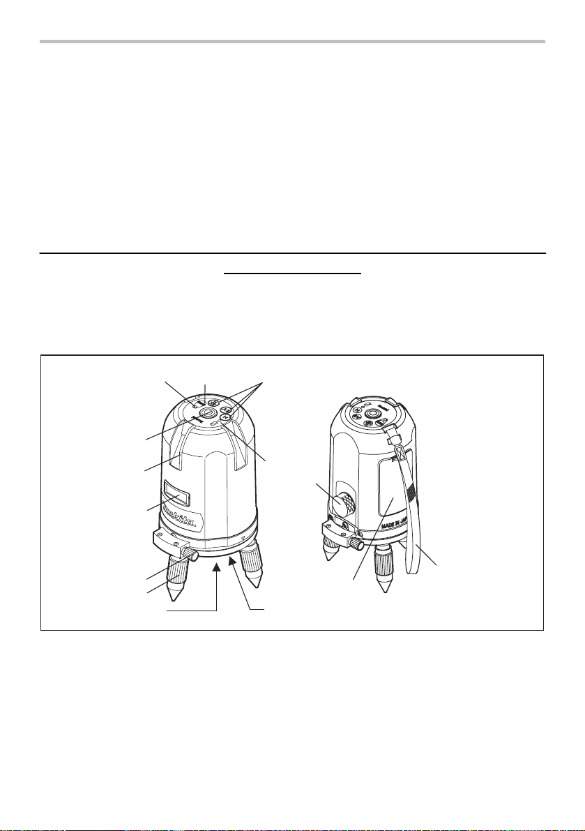
1. Operating-mode selecting buttons
(H, 2V,2V/H)
2. Interior/exterior mode change button
3. Exterior mode indicator LED (green)
4. Round vial with backlight
4
6
7
8
9
11
Explanation of general view
5. Battery life indicator LED (yellow)
6. Exit opening for vertical laser beam
7. Exit opening for horizontal laser beam
8. Fine rotation-adjusting knob
9. Level adjusting ring
123
5
12
13
10
10. Tripod connection
11. Exit opening for plumb laser beam
12. Power switch (Switch lock provided)
13. Battery cover
14. Tool-strap
14
3
Page 4

Attaching and replacing batteries (Fig.1)
Horizontal
Fig. 1
Makita SK20 exclusive
uses Elevating Tripod.
Fig. 2
OPERATION
Fig. 3
1. Turn on the power switch (12). The unit (laser
level) projects the horizontal laser- beam line.
2. If the unit is placed in a slanting position, it will not
emit any laser lines at all. Adjust the level
adjusting ring (9) so that the air-bubble in the
round vial (4) is centered. (See the Fig. 3)
3. If you work with the receiver (optional accessory),
press the interior/exterior mode change button (2).
Exterior mode indicator LED (green) (3) will light
on.
Following 3 operation modes are available. Press
the most suitable operating-mode selecting button
(1) according to your job.
Fig. 4
Press the H button. The unit projects the horizontal
laser-beam line as illustrated in Fig.4.
You can adjust the height of the horizontal laser
line by mounting the unit to Elevating tripod
provided
(See the Fig. 2)
Vertical + Right angle (Vertical) + Plumb Point (floor)
Fig. 5
Press the 2V button. The unit projects the vertical
laser-beam lines as illustrated in Fig.5.
Vertical + Right angle (Vertical) + Horizontal + Plumb
Point (floor)
Fig. 6
Press the 2V/H button. The unit projects the
laser-beam lines (2 vertical and horizontal ones) as
illustrated in Fig.6.
4. Turn off the power switch after operation. The unit
will be automatically locked.
4
Page 5

Inspection of the leveling accuracy of the
laser level
Check the leveling accuracy of the unit (laser level)
periodically in the following manners:
2) Turn on the power switch 12. Then press the
V button.
3) Direct the vertical laser line to the string of
plumb-bob. Then adjust the vertical laser line
to the lower end of the string. Make sure that
deviation from the vertical laser line to the
upper end of the string is within the leveling
accuracy specified.
Fig. 7
1. Check the leveling accuracy of horizontal
laser-beam line.
1) Place the unit on the floor of an indoor corner
at the point of 3 to 5 m from the one wall and
1 m from the another one. (See the Fig.7)
Turn the level adjusting ring (9 ) so that the
air-bubble in the round vial (4) is centered.
2) Turn on the power switch (12).
3) Turn the unit and mark both ends of laser line
projected on the both walls.
4) Then turn the unit on both sides. Make sure
that half of the deviation from laser line to the
first marked point is within the leveling
2. Check the leveling accuracy of vertical
Fig. 8
accuracy specified.
laser-beam line.
1) Hang a plumb-bob (See the figure 8) from 3
m height of the wall (the height of ceiling is
approx. 3 m).
Place the unit on the floor at the point of 2 to
5 m away from the wall. Make sure that the
air-bubble is centered in the round vial (4).
5
Page 6

6 7 8
Page 7

Page 8

Makita Corporation
 Loading...