

Makita MAC500 User guide
OWNERS MANUAL
FOR
Oil-less
Air
Compressor
MODEL
NO.
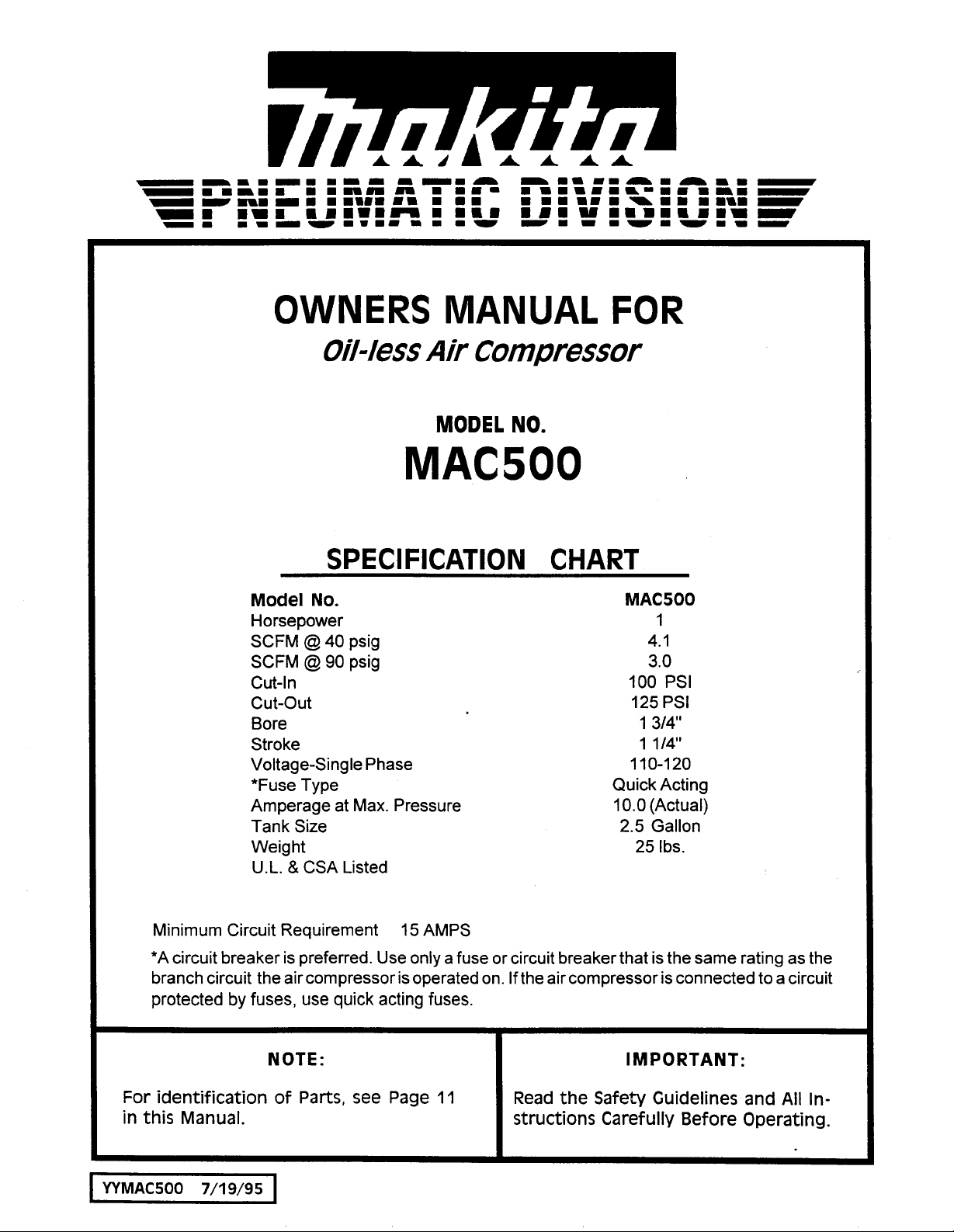
MAC500
SPECIFICATION CHART
Model
Horsepower 1
SCFM
SCFM
Cut-In
cut-out 125
Bore 1 3/4"
Stroke 1 1/4"
Voltage-Single Phase
*Fuse Type Quick Acting
Amperage at Max. Pressure
Tank Size
Weight
U.L.
No.
@
40
psig 4.1
@
90
psig 3.0
&
CSA Listed
MAC500
100
PSI
PSI
11
0-1
10.0
(Actual)
2.5
Gallon
25
Ibs.
20
Minimum Circuit Requirement
*A
circuit breaker is preferred. Use only a fuse or circuit breaker that is the same rating as the
branch circuit the air compressor is operated on. If the air compressor is connected to
I
protected
For identification of
in this Manual.
I
I
WMAC500
7/19/95
15
by
fuses, use quick acting fuses.
NOTE:
Parts,
see
Page
I
AMPS
11
IMPORTANT:
Read the Safety Guidelines and
structions Carefully
Before
I
a
circuit
All
In-
Operating.
TABLE
OF
CONTENTS
SAFETY GUIDELINES
WARNING CHART
GLOSSARY
DUTY CYCLE
STORAGE
DESCRIPTION
INSTALLATION AND BREAK-IN
PROCEDURES
Location
...........................................
........................................
..............................................
OF
..................................
of
Air Compressor
..........................
.............................
OPERATION
............ 6
Page
3-4
...........
6.7
3
5
5
5
6
Voltage and Circuit Protection
Extension Cords
Grounding Instructions
Additional Regulators and
Controls
Break-In Procedures
OPERATING PROCEDURES
TROUBLESHOOTING GUIDE
COMPRESSOR PARTS LIST
WARRANTY/FACTORY SERVICE
CENTERS
.............................................
.............................
................................
........................
..........................
...........
...............
.......
.............
Back Cover
Page
6
6
7
7
7
8
9-10
11
2
SAFETY
GUIDELINES
This manual contains information that
YOUR
following symbols. Please read the manual and pay attention to these sections.
SAFETY
and PREVENTING EQUIPMENT PROBLEMS. To help you recognize this information, we use the
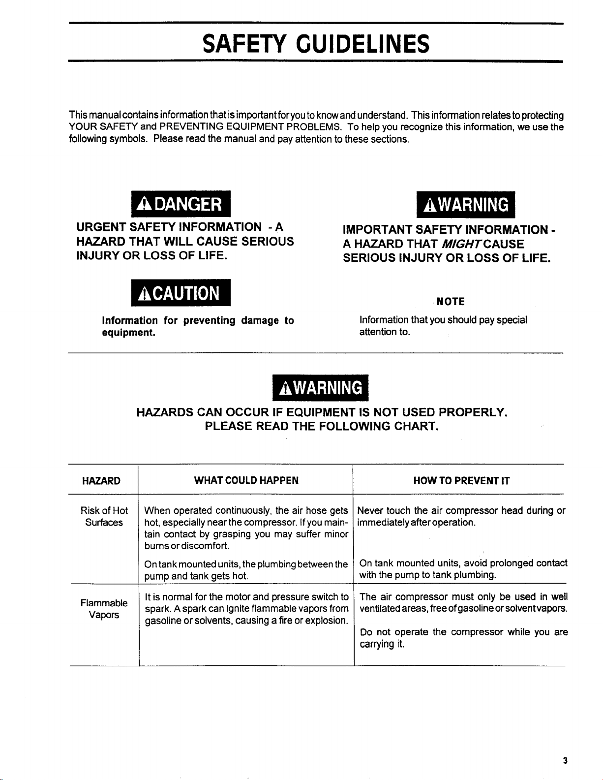
URGENT SAFETY INFORMATION -A
HAZARD THAT WILL CAUSE SERIOUS
INJURY OR LOSS OF LIFE.
Information for preventing damage to
equipment.
is
important for you
to
know and understand. This information relates to protecting
IMPORTANT SAFETY INFORMATION
A
HAZARD THAT MGHTCAUSE
SERIOUS INJURY OR LOSS OF LIFE.
Information that
attention to.
NOTE
you
should pay special
-
HAZARD
Risk
of
Hot
Surfaces
Flammable
Vapors
HAZARDS CAN OCCUR IF EQUIPMENT
PLEASE READ THE FOLLOWING CHART.
WHAT COULD HAPPEN
When operated continuously, the air hose gets
hot, especially near the compressor. If you maintain contact by grasping you may suffer minor
burns or discomfort.
On tank mounted units, the plumbing between the
pump and tank gets hot.
It is normal for the motor and pressure switch to
A
spark.
gasoline or solvents, causing a fire or explosion.
spark can ignite flammable vapors from
IS
NOT USED PROPERLY.
HOW
TO PREVENT
Never touch the air compressor head during or
immediately after operation.
On tank mounted units, avoid prolonged contact
to
with the pump
The air compressor must only be used in well
ventilated areas, free
Do
not operate the compressor while you are
carrying it.
tank plumbing.
of
gasoline or solventvapors.
IT
3
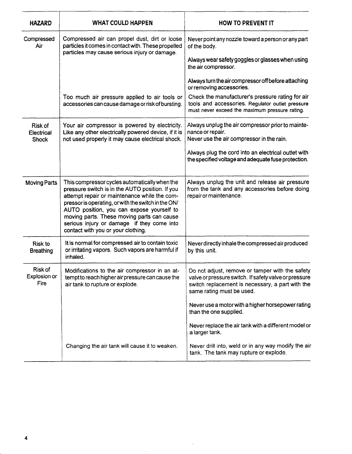
HAZARD
WHAT COULD HAPPEN
HOW TO PREVENT IT
Compressed
Air
Risk of
Electrical
Shock
Moving Parts
;ompressed air can propel dust, dirt or loose
)articles it comes in contact with. These propelled
)articles may cause serious injury or damage.
roo
much air pressure applied to air tools or
accessories can cause damage or risk of bursting.
lour air compressor is powered by electricity.
ike any other electrically powered device, if it is
lot used properly it may cause electrical shock.
This compressor cycles automatically when the
Dressure switch is in the
AUTO
position. If you
attempt repair or maintenance while the comDressor is operating, orwith the switch in the
ON/
AUTO position, you can expose yourself to
moving parts. These moving parts can cause
serious injury or damage if they come into
contact with you or your clothing.
Jever point any nozzle toward a person orany part
)f
the body.
Uways
wear
safety goggles
or
glasses
when
using
he air compressor.
Uways turn the air compressor
off
before attaching
)r removing accessories.
:heck the manufacturer's pressure rating for air
001s
and accessories. Regulator outlet pressure
nust
never exceed the maximum pressure rating.
ilways unplug the air compressor prior to maintelance or repair.
Jever use the air compressor in the rain.
ilways plug the cord into an electrical outlet with
he specified voltage and adequate fuse protection.
~~
{lways unplug the unit and release air pressure
rom the tank and any accessories before doing
epairor maintenance.
Risk to
Breathing
Risk of
Explosion or
Fire
It
is normal for compressed air to contain toxic
or irritating vapors. Such vapors are harmful if
inhaled.
Modifications to the air compressor in an atternptto reach higherairpressurecancause the
air tank to rupture or explode.
Changing the air tank will cause it to weaken.
Jeverdirectly inhale the compressed air produced
)y this unit.
Do
not adjust, remove or tamper with the safety
ialve or pressure switch. If safety valve or pressure
switch replacement is necessary, a part with the
same rating must be used.
Never use a motorwith a higher horsepower rating
than the one supplied.
Never replace the air tank with a different model or
a larger tank.
Never drill into, weld or in any way modify the air
or
tank. The tank may rupture
explode.
4
GLOSSARY
SCFM
measurement of air delivery.
PSlG
CUT-IN
pressure drops as you continue to use your accessory.
When the tank pressure drops to approximately
the motor will restart automatically. The low pressure at
which the motor automatically re-starts is called "cut-in
pressure."
or
CFM:
or
PSI:
Pounds per square inch gauge.
PRESSURE:
Standard Cubic Feet per Minute; a unit of
While the motor is
off,
air tank
100
PSI
DUN
CUT-OUT PRESSURE:
pressor and it begins to run, air pressure in the air tank
begins to build. It builds to to approximately
the motor automatically shuts
which the motor shuts
When you turn on your air com-
125
PSI
before
off
.The high pressure at
off
is called "cut-out pressure."
CYCLE
This air compressor's optimum life may be achieved by operating the unit at a
A
50%
duty cycle is considered
Should the unit operate at a greater than a
required job demand and continued operation above a
to
be
30
minutes of 'run time' in any 1 hour time period.
50%
duty cycle, then the compressor may be undersized for the
50%
duty cycle may constitute misuse of the product.
STORAGE
When
you
have finished using the air compressor:
3. Protecttheelectrical cord and air hose from damage by
1.
Setthe"0NIOFF" switch to"0FF"and unplug the cord.
2.
Relieve all pressure from the aircompressor head and
air hose by opening the regulator.
winding them loosely around the air compressor.
4.
Store the air compressor in a clean and dry location.
50
% duty cycle, or less.
5
DESCRIPTION
OF
OPERATION
Air Compressor Pump:
moves up and down in the cylinder. On the downstroke, air
isdrawn in through theairintakevalves. Theexhaustvalves
remain closed. On the upstroke of the piston, air is
compressed. The intake valves close and compressed air
is forced out through the exhaustvalves, through theoutlet
tubes, through the check valve and into the air tank.
Working air is not available until the compressor has raised
the air tank pressure above that required at the air outlet.
Check Valve:
checkvalve is’lopen”, allowing compressed air toenter the
air tank. When the air compressor reaches “cut-out”
pressure, the check valve “closes”, allowing air pressure to
remain inside the air tank.
Pressure Switch:
starts the motorwhen the air tank pressure drops below the
factory set “cut-in’’ pressure. It stops the motor when the
airtank pressure reaches the factory set”cut-out” pressure,
Regulator:
controlled by the regulator. Turn the regulator knob clockwise to increase pressure and counter-clockwise to
decrease pressure. To avoid minor readjustment after
making a change in pressure setting, always approach the
desired pressure from a lower pressure. When reducing
from a higher to a lower setting, first reduce to some
pressure less than that desired, then bring up to the desired
When the air compressor
The air pressure coming from the air tank is
To compress air, the piston
is
operating, the
The pressure switch automatically
pressure. Depending on the air requirements of each
particular accessory, the outlet regulated air pressure may
have to be adjusted while operating the accessory.
Outlet Pressure Gauge:
indicates the air pressure available at the outlet side of the
regulator. This pressure is controlled by the regulator and
is always less or equal to the tank pressure. See “Operating Procedures”.
Tank Pressure Gauge:
the reserve air pressure in the tank.
Cooling System:
design cooling system. At the heart of this cooling system
is an engineered fan.
air through the vent holes in large amounts. You know that
the cooling system is working when air is being expelled.
Air Intake Filter:
unique design of the air intake system.
Drain Valve:
air tank and is used to drain condensation at the end of each
use.
OnlAuto-Off Switch:
automatic powerto the pressure switch and
power at the end of each use.
This compressor contains an advanced
It
The unit requires
The drain valve is located at the base of the
The outlet pressure gauge
Thetank pressuregauge indicates
is perfectly normal forthis fan to blow
no
air filter due
Turn this switch
ON
OFF
to
the
to provide
to remove
INSTALLATION AND BREAK4N PROCEDURES
Location
Your compressor comes to you completely assembled
and ready for use. Operate the air compressor in a dry,
clean, cool and well ventilated area. The air compressor
pump and case are designed to allow for proper cooling.
Clean or blow
compressor. A clean air compressor runs cooler and
provides longer service. The ventilation openings on your
air compressorare necessary to maintain proper operating
temperature.
near these openings.
of
the Air Compressor
off
dust or dirt that collects on the air
Do
not place rags or other containers on or
Voltage and Circuit Protection
See front cover.
6
Extension Cords
Use extra air hose instead of an extension cord to avoid
voltage drop and power
sized cord will cause a drop in the line voltage resulting
loss
of power and overheating.
in
If an extension cord must be used, be sure it is:
a 3-wire extension cord that has a 3-blade grounding plug, and a 3-slot receptacle that will accept the
plug on the compressor
in good condition
no longer than
14 gauge (AWG) orlarger. (Wire size increases as
gaugenumberdecreases.) 12AWG, 10AWGand
8
AWG
may also be used.
AWG.
50
loss
feet
to the motor. An under-
DO
NOT
USE
16 OR
18
INSTALLATION AND BREAK-IN
PROCEDURES
GROUNDING INSTRUCTIONS
RISK
OF
ELECTRICAL SHOCK! IN THE EVENTOF A
SHORTCIRCUIT,GROUNDING REDUCESTHE RISK
OFSHOCKBY PROVlDlNG AN ESCAPEWIRE FOR
THE ELECTRICCURRENT. THISAIRCOMPRESSOR MUST BE PROPERLY GROUNDED.
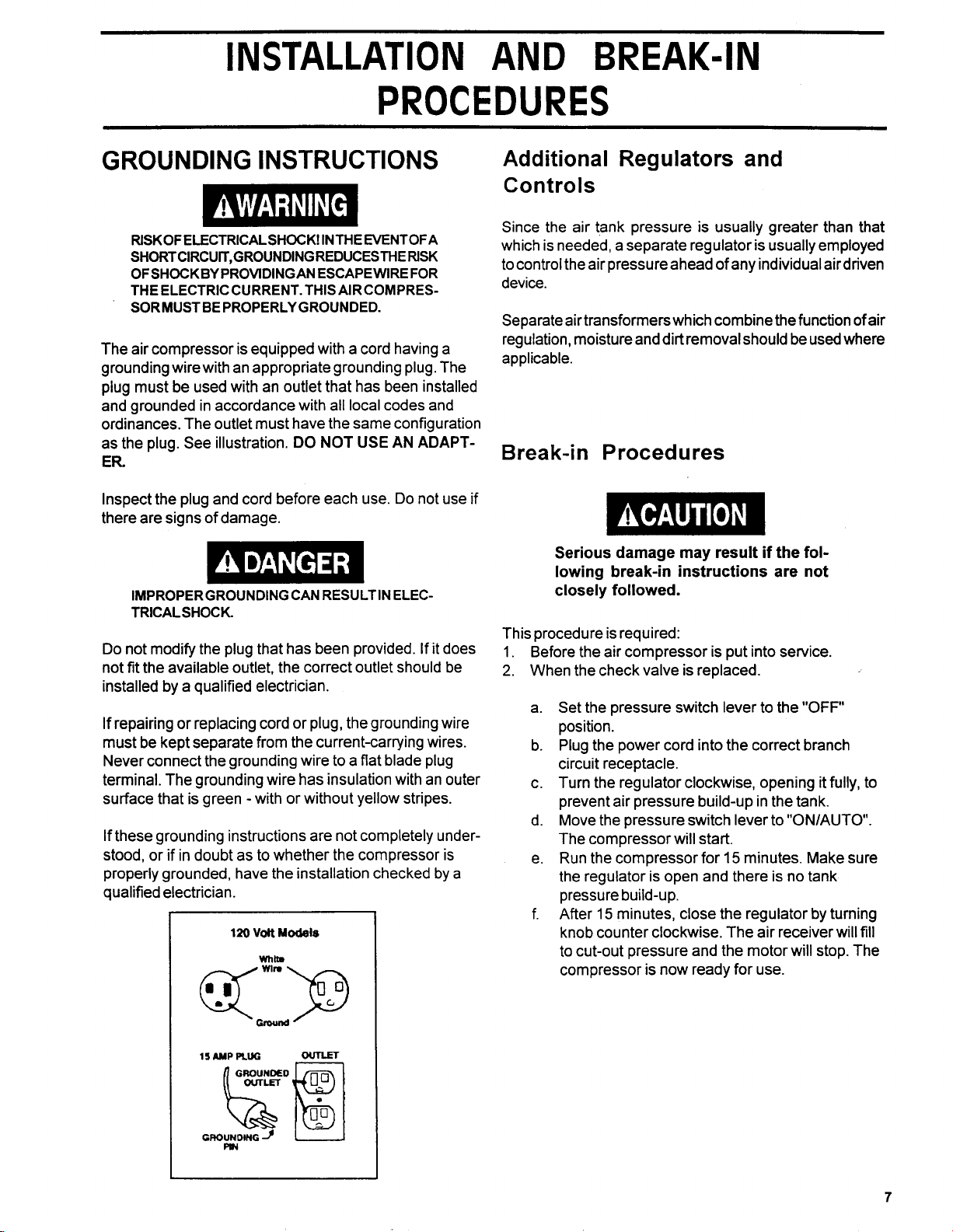
The air compressor is equipped with a cord having a
grounding wirewith an appropriate grounding plug. The
plug must be used with an outlet that has been installed
and grounded in accordance with all local codes and
ordinances. The outlet must have the same configuration
as the plug. See illustration.
ER
Inspect the plug and cord before each use.
there are signs of damage.
IMPROPERGROUNDING CAN RESULTIN ELEC-
TRICALSHOCK.
Do
not modify the plug that has been provided. If
not fit the available outlet, the correct outlet should be
installed by a qualified electrician.
If repairing or replacing cord or plug, the grounding wire
must be kept separate from the current-carrying wires.
Never connect the grounding wire to a flat blade plug
terminal. The grounding wire has insulation with an outer
surface that is green -with or without yellow stripes.
If these grounding instructions are not completely under-
stood, or if in doubt as to whether the compressor is
properly grounded, have the installation checked by a
qualified electrician.
DO
NOT
USE
AN
ADAPT-
Do
not use if
it
does
Additional Regulators and
Con
t
ro
Is
Since the air tank pressure is usually greater than that
is
which is needed, a separate regulator
to control the air pressure ahead of any individual air driven
device.
Separate air transformers which combine the function of air
regulation, moisture and dirt removal should be used where
applicable.
usually employed
Break-in Procedures
Serious damage may result if the following break-in instructions are not
closely followed.
This procedure is required:
1.
Before the air compressor is put into service.
2.
When the check valve is replaced.
Set the pressure switch lever to the
a.
position.
Plug the power cord into the correct branch
b.
circuit receptacle.
Turn the regulator clockwise, opening it fully, to
C.
prevent air pressure build-up in the tank.
d.
Move the pressure switch lever to
The compressor will start.
Run the compressor for
e.
the regulator is open and there is no tank
pressure build-u p.
After
15
f.
knob counter clockwise. The air receiver will
to cut-out pressure and the motor will stop. The
compressor is now ready for use.
minutes, close the regulator by turning
15
minutes. Make sure
"OFF"
"ONIAUTO.
fill
7
OPERATING PROCEDURES
1.
Before attaching air hose or accessories, make sure
the OFFlAUTO lever is set to "OFF" and the air
regulator or shut-off valve is closed.
2.
Attach hose and accessories. pressure to zero.
TOO MUCH AIR PRESSURE CAUSES A HAZARDOUS RISKOF BURSTING. CHECKTHE MANUFACTURERS MAXIMUM PRESSURERATING FORAIR
TOOLS AND ACCESSORIES. THE REGULATOR
OUTLET PRESSURE MUST NEVER EXCEEDTHE
MAXIMUM PRESSURE RATING. ON MODELS HAVING ONLYASHUT-OFFVALVE, YOU MUST INSTALL
A REGULATOR BEFORE USING ACCESSORIES
125
RATEDATLESSTHAN
3.
Turn the OFF/AUTO lever to "AUTO" and allow tank
PSIG.
pressure to build. Motor will stop when tank pressure
reaches"cut-out" pressure.
When youare finished:
6.
Setthe"OFF/AUTO"leverto"OFF".
7.
Tum
the
8.
Remove the air tool or accessory.
9. Open the regulator and allow the air to slowly bleed
from the tank. Close the regulatorwhen tank pressure
is approximately
10.
Drain water from air tank. By opening drain valve
underneath the tank.
WATERWILLCONDENSEIN THEAIRTANK. IF
NOTDRAINED, WATERWILLCORRODE AND
WEAKEN THE AIR TANK CAUSING A RISK OF
AIRTANK RUPTURE.
regulatorcounterclockwiseand set theoutlet
.
20
psi.
Open the regulator by turning it clockwise. Adjust the
4.
regulator to the correct pressure setting. Your compressor is ready for use.
Always operate the air compressor
5.
in
well-ventilated
areas; free of gasoline or other solvent vapors. Do not
operate the compressor near a paint spray area.
NOTE
If drain cock valve is plugged, release all air
pressure. The valve
cleaned,
11.
Afterthewater has been drained, closethedrain cock
then
can
reinstalled.
then be removed,
ordrainvalve. Theaircompressorcan now bestored.
8
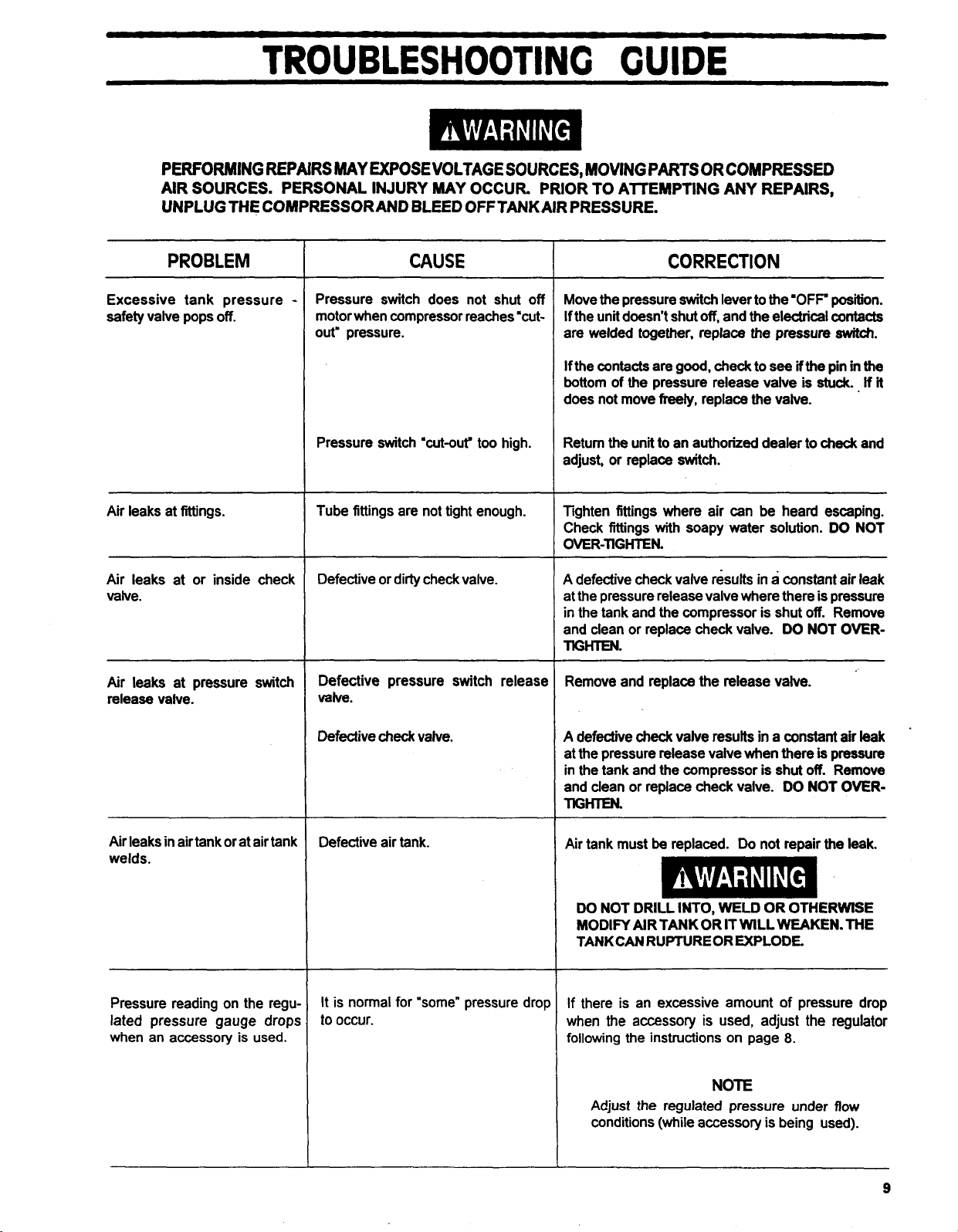
TROUBLESHOOTING
GUIDE
PERFORMING REPAIRS
AIR SOURCES. PERSONAL INJURY MAY OCCUR. PRIOR TO ATTEMPTING ANY REPAIRS,
UNPLUG THE COMPRESSOR
PROBLEM
Excessive tank pressure
safely valve pops
Air leaks at fittings.
Air leaks at or inside check
valve.
off.
MAY
EXPOSEVOLTAGE
AND
BLEED
OFFTANK
CAUSE
Pressure switch does not shut
-
motor when compressor reaches 'cut-
out,
pressure.
Pressure switch 'cut-out' too high.
Tube fittings are not tight enough.
~
Defective or dirty check valve.
SOURCES, MOVING PARTS OR COMPRESSED
AIR PRESSURE.
CORRECTION
off
Move the pressure switch lever to the
off,
f the unit doesn't shut
ore
welded
If the contacts are
mttom
joes not move
2etum the unit to an authorized dealer to
adjust, or replace
fighten fittings where air can be heard escaping.
:heck fittings
3VER-TIGHIEN.
~~ ~ ~ ~ ~~ ~
9
defective check valve results in a constant air leak
at the pressure release valve where there is pressure
n the tank and the compressor is shut
and clean or replace check valve.
ffim.
together, replace the pressure
good,
of the pressure release valve is
freely,
with
and the electrical
check to
replace the valve.
switch.
soapy water solution. DO NOT
'OFF
position.
contacts
see
if
the pin
stuck..
check and
off.
DO NOT OVER-
switch.
in
the
If
it
Remove
Air
leaks
at pressure switch
release valve.
Air leaks in air tank or at air tank
welds.
Pressure reading on the regu
lated pressure gauge drop!
when an accessory is used.
Defective pressure switch release
valve.
check
Defective
Defective air tank.
It
is
normal for "some" pressure drop
to
occur.
valve.
Remove and replace the release valve.
9
defective
nt the pressure release valve when there
n the tank and the compressor is shut
nnd clean or replace
nGm.
Air tank must
DO NOT DRILL INTO, WELD OR OTHERWE
MODIFY AIRTANKOR ITWlLLWEAKEN.THE
TANKCAN
If there
when the
following the instructions on page
check
valve results in a constant
check
valve.
DO
be
replaced. Do not repair the
RUPTUREOREXPLODE.
is
an excessive amount of pressure drop
accessory
is
used, adjust
8.
air
is
pressure
off.
Remove
NOT OVER-
the
regulator
leak.
NOTE
Adjust the regulated pressure under
conditions (while
accessory
is
being used).
flow
leak

TROUBLESHOOTING
GUIDE
(Continued)
PROBLEM
Air leak from safety valve.
Knocking Noise
Compressor is not supplying
enough air to operate accessories.
Motor will not run.
CAUSE
Possible defect in safety valve.
Defective check valve.
Prolonged excessive use of air.
Compressor is not large enough for
air requirement.
Hole in hose.
Check valve restricted.
Air leaks.
Tank pressure exceeds pressure
switch "cut-in" pressure.
Wrong gauge wire or length of exten
sion cord.
CORRECTION
Operate safety valve manually by pulling on ring.
valve still leaks, it should be replaced.
Remove and clean, or replace.
Decrease amount of air usage.
Check the accessory air requirement. If
than the SCFM or pressure supplied by your air
compressor, you need a larger compressor.
Check and replace if required.
Remove and clean, or replace.
Tighten fittings. (See Air Leaks Section of
Troubleshooting Guide.)
Motor will start automatically when tank pressure
drops below "cut-in" pressure of pressure switch.
Check for proper gauge wire and cord length.
it
If
is higher
Check valve stuck open.
Loose electrical connections.
Paint spray on internal motor parts.
Possible defective motor.
Fuse blown, circuit breaker tripped.
Pressure release valve on pressur
switch has not unloaded head prez
sure.
Remove and clean, or replace.
Check wiring connection inside pressure switch and
terminal box area.
-lave checked at an Authorized Warranty Senrice
Senter.
spray area.
iave checked at an Authorized Warranty Service
:enter.
1.
2.
3.
4.
Bleed the line by pushing the lever on the pressure
switch
replace it.
Do
not operate the compressor in the paint
See flammable vapor warning.
Check fuse box for blown fuse and replace, if
necessary. Reset circuit breaker. Do not use a
fuse or circuit breakerwith higher rating than that
specified for your particular branch circuit.
Check for proper fuse; on1y"Fusetron" typeT
equivalent) fuses are acceptable.
Check for low voltage conditions and/or proper
extension cord.
Disconnect the other electrical appliances from
circuit or operate the compressor in its own
branch circuit.
to
the
"off
position; if the valve does not open,
(or
Regulator knob continuous ai
leak. Regulator will not shut
at air outlet.
10
of
Dirty or damaged regulator internz
parts.
Clean or replace regulator, or internal parts.
PRESSURE
SAFETY VALV
R
GAUGE
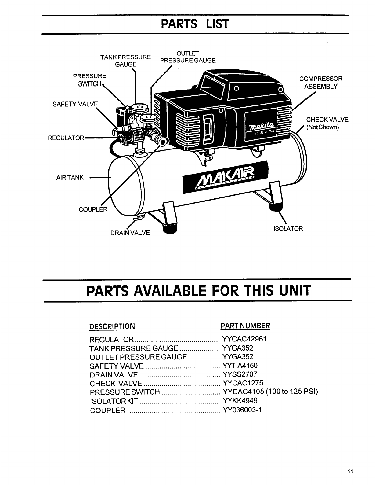
PARTS
OUTLET
PRESSURE
GAUGE
LIST
CHECKVALVE
PARTS AVAILABLE
DESCRl PTlON PART NUMBER
REGU IATOR
TANK PRESSURE GAUGE
OUTLETPRESSURE GAUGE
SAFETY VALVE
DRAIN VALVE
CHECK VALVE
PRESSURE SWITCH
ISOLATOR KIT
COUPLER
..........................................
....................
...............
.....................................
........................................
......................................
.............................
........................................
..............................................
FOR
YYCAC4296
YYGA352
YYGA352
yyTIA4150
YYSS2707
YYCAC1275
YYDAC4105 (1
YYKK4949
YYO36003-1
THIS
1
UNIT
00
to
125
PSI)
11
 Loading...