

Makita MAC1200 User Manual
.
OWNERS
MANUAL
FOR
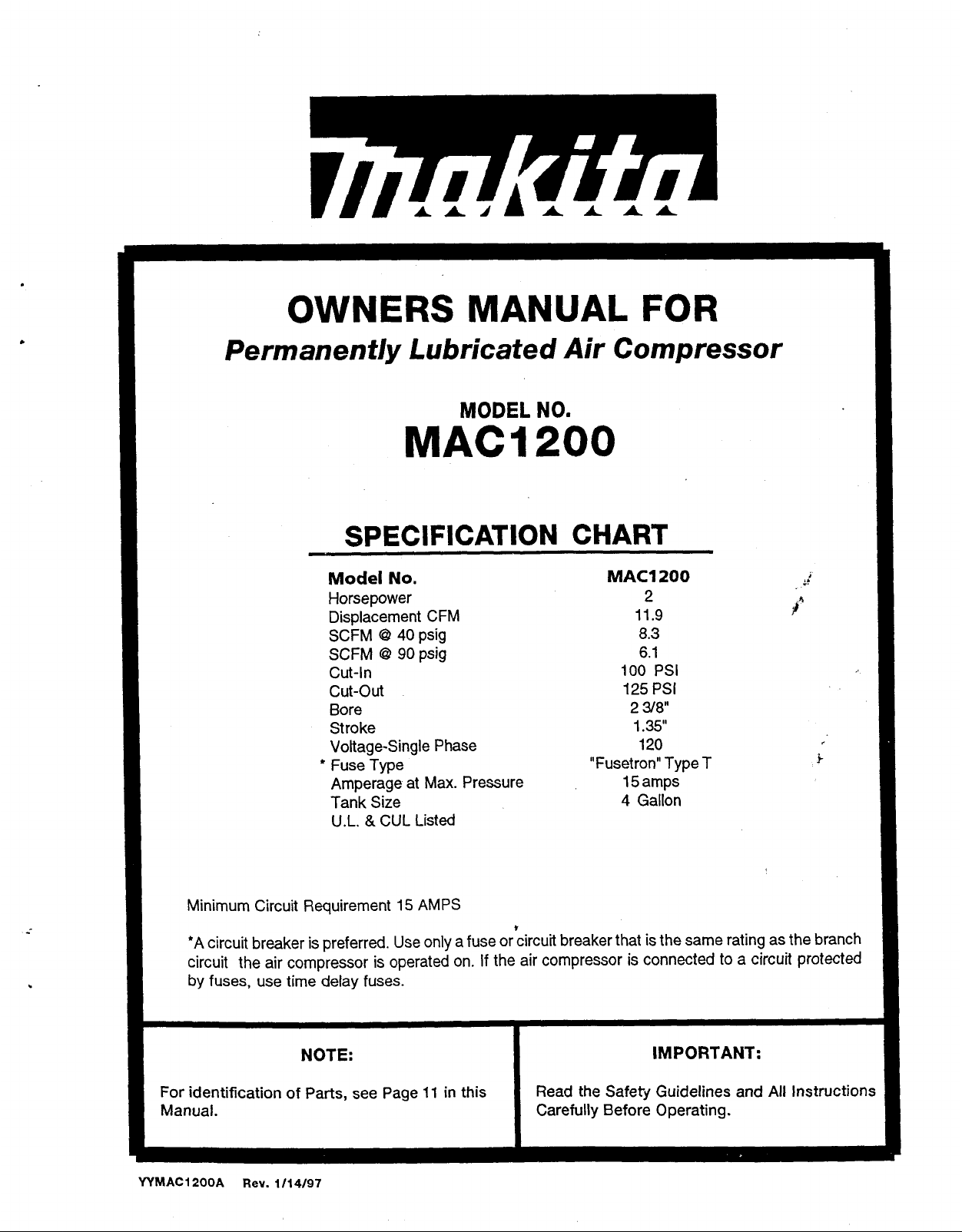
Permanently Lubricated Air Compressor
MODEL
MAC1
NO.
200
SPECIFICATION CHART
Model
Horsepower
Displacement CFM
SCFM
SCFM
Cut-In
cut-out
Bore
Stroke
Voltage-Single Phase
+
Fuse Type
Amperage
Tank Size
U.L.
No.
G2
40
G2
9Opsig
at
&
CUL Listed
psig
Max. Pressure
MAC?
"Fusetron" Type T
200
2
11.9
8.3
6.1
100
PSI
125
PSI
2
38"
1.35"
120
15 amps
4
Gallon
,
;c*
k
Minimum Circuit Requirement
+A
circuit breaker is preferred. Use only a fuse or circuit breaker that is the same rating as the branch
circuit the air compressor is operated on.
by
fuses, use time delay fuses.
NOTE: IMPORTANT:
For
identification
Manual. Carefully Before Operating.
WMAC12QQA
Rev.
of
Parts, see Page 11 in
~
1/14/97
15
AMPS
I
If
the air compressor is connected to a circuit protected
this
Read the Safety Guidelines and
All
Instructions
TABLE
OF
CONTENTS
SMETYGUIDELINES
WARNING
GLOSSARY
DUTYCYCLE
GENERAL INFORMATION
ON-RECEIPTINSPECTION
DESCRIPTION
INSTALLATION
pROCEDURES
CHART
...............................................................
.............................................................
OF
.......................................................
Location
Lubrication and Oil
Extension Cords
Piping
Grounding Instructions
Additional Regulators & Controls
Break-in Procedures
of
...............................................................
...............................................
.................................................
........................................
.........................................
OPERATION
AND
BREAK-IN
Air Compressor
...........................................
................................................
...........................................
..................................
..............................
...................................
.......................
Page
2
34
5
5
5
5
5
6-7
6
6
6
6
67
7
7
OPERATING PROCEDURES
Daily Start-up Checklist
MAINTENANCE
Air Filter . Inspection and Replacement
Safety Valve . Inspection
Check Valve Replacement
Motor
.................................................................
STORAGE
TROUBLESHOOTING GUIDE
AIR COMPRESSOR DIAGRAM
AIR COMPRESSOR PARTS LIST
AIR COMPRESSOR PUMP DIAGRAM
AIR COMPRESSOR PUMP PARTS LIST
WARRANIY
......................................................
...............................................................
STATEMENT
..................................
.....................................
...................................
.................................
.............................
.............................
..........................
.........................
Page
.............
9-10
..................
...............
Back
Cover
f
7
7
8
8
8
8
8
9
11
12
13
14
r
This manual contains information that is important for you to
know and understand
mation relates
SAFETY
MENT
recognize this information. we use
I
symbols
the
these sections
andPREVENTINGEQUIP-
PROBLEMS
SAFETY
.
This infor-
to
protecting
to
the right. Please read
and
pay
.
YOUR
.
To help you
I
GUIDELINES
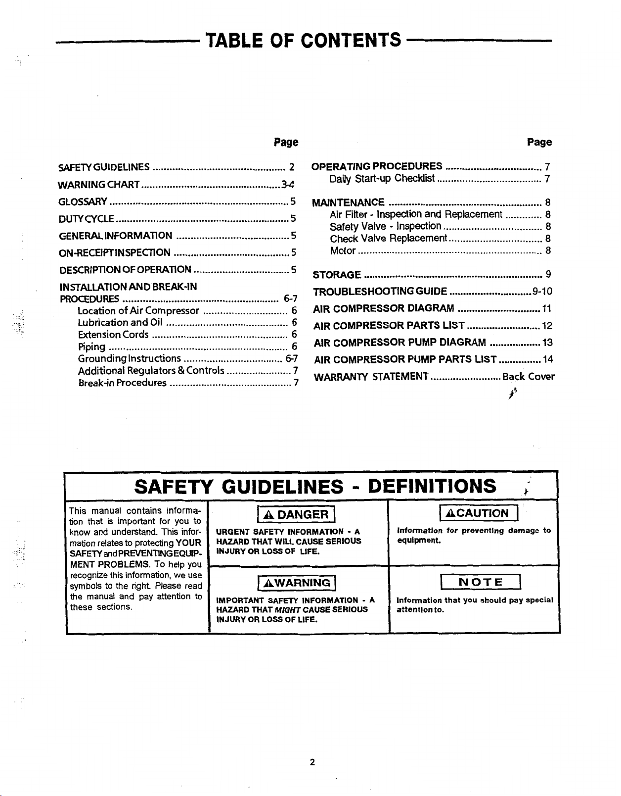
URGENT SAFETY INFORMATION
HAZARD
INJURY
I
to
IMPORTANT SAFETY INFORMATION
HAZARD
INJURY
I
THAT WILL CAUSE
OR
LOSS
OF
LIFE
1
AWARNING
THAT
MIGHT
OR
LOSS
OF
CAUSE
LIFE
SERIOUS
.
.
2
.
.
A
I
SERIOUS
DEFINITIONS
.
Information
equipment
A
Information that
attention to
for
preventing
.
1
NOTE
you should pay special
.
I
i
damage
I
to
IMPORTANT
SAVFTHESF INSTRUCTION
SAFETY
INSTRUCTIONS
s*
I=-
-
RISK
IMPROPER OPERATION
:NJURY
INSTRUCTIONS BEFORE USING THIS EQUIPMENT.
I
AND PROPERTY DAMAGE. READ AND UNDERSTAND ALL WARNINGS AND OPERATING
HAZARD
4ir
m
OF
BURSTING
1
Attachments
OR
MAINTENANCE
WHAT CAN HAPPEN
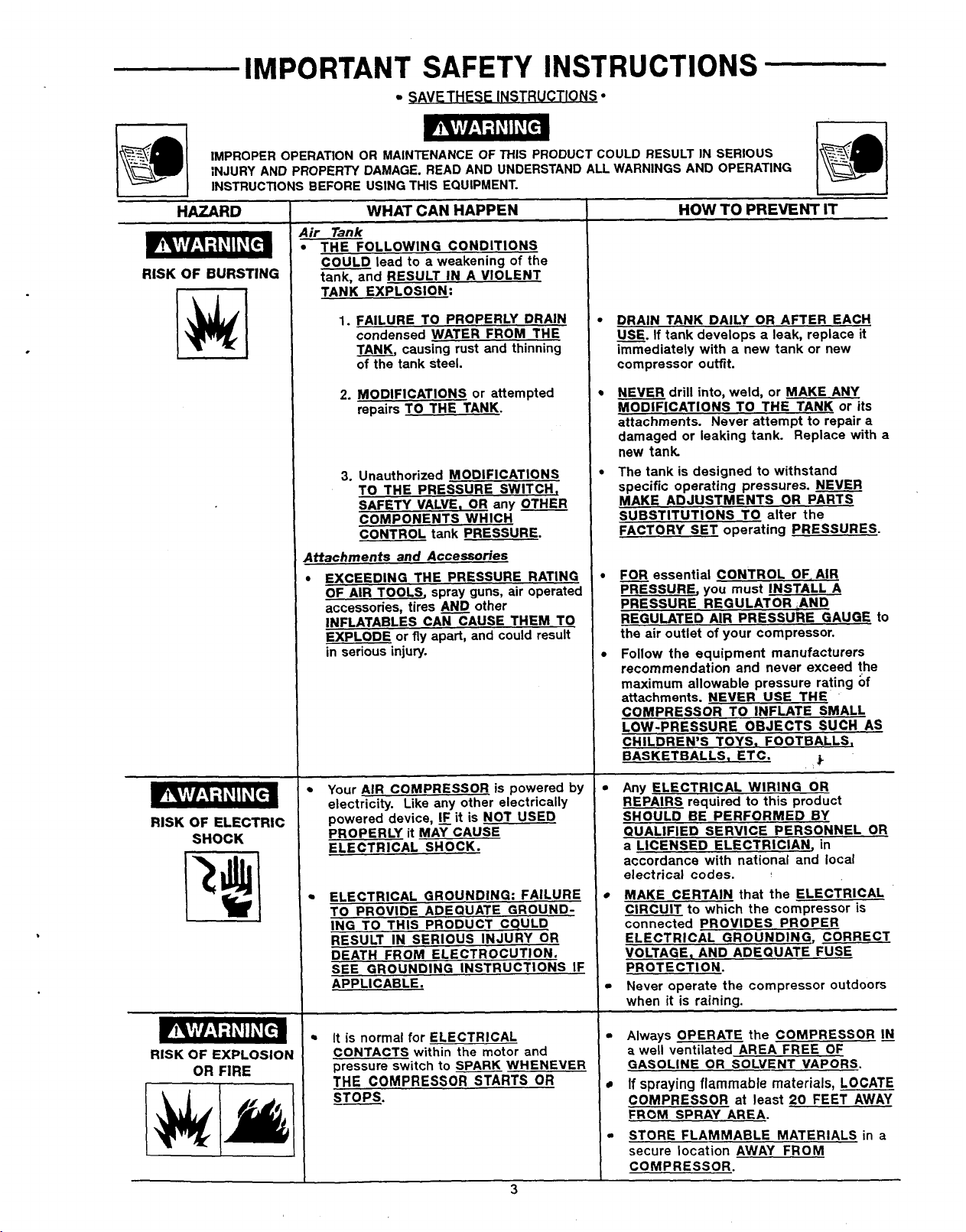
Tank
THE FOLLOWING CONDITIONS
COULD lead to a weakening of the
tank,nd RESULT IN A VIOLENT
TANK EXPLOSION:
1.
FAILURE TO PROPERLY DRAIN
condensed WATER FROM THE
TANK, causina rust and thinning
of the tank steel.
2.
MODIFICATIONS or attempted
repairs TO THE TANK.
and
Accessories
EXCEEDING THE PRESSURE RATING
OF AIR TOOLS, spray guns, air operated
accessories, tires other
INFLATABLES CAN CAUSE THEM TO
EXPLODE or fly apart, and could result
in serious injury.
OF
THIS
PRODUCT COULD RESULT
0
DRAIN TANK DAILY
-
USE.
immediately with a new tank or new
compressor outfit.
NEVER drill into, weld, or MAKE ANY
MODIFICATIONS TO THE TANK
attachments. Never attempt to repair a
damaged or leaking tank. Replace with a
new tank
1
The tank is designed to withstand
specific operating pressures. NEVER
MAKE ADJUSTMENTS
SUBSTITUTIONS TO alter the
FACTORY SET operating PRESSURES.
m
-
FOR essential CONTROL OF. AIR
PRESSURE, you must INSTALL A
PRESSURE REGULATOR .AND
REGULATED AIR PRESSURE GAUGE
the air outlet of your compressor.
Follow the equipment manufacturers
recommendation and never exceed the
maximum allowable pressure rating of
attachments. NEVER
COMPRESSOR TO INFLATE SMALL
LOW-PRESSURE OBJECTS SUCH
CHILDREN’S TOYS. FOOTBALLS,
BASKETBALLS. ETC.
IN
SERIOUS
I
HOW
TO
PREVENT
OR
If
tank develops a leak, replace it
USE
IT
AFTER EACH
OR
Pm
THE
i
or
its
to
AS
RISK
OF
ELECTRIC
SHOCK
RISK OF EXPLOSlOh
OR
FIRE
Your AIR COMPRESSOR is powered
electricity. Like anv other electricallv
powered-device,-&it is NOT USED
PROPERLY
ELECTRICAL SHOCK.
ELECTRICAL GROUNDING: FAILURE
TO PROVIDE ADEQUATE GROUND-
ING TO THIS PRODUCT CQULD
RESULT
DEATH FROM ELECTROCUTION.
SEE GROUNDING INSTRUCTIONS IF
APPLICABLE.
It
is normal
CONTACTS within the motor and
pressure switch
THE
STOPS.
it
MAY CAUSE
IN
SERIOUS INJURY
for
ELECTRICAL
to
SPARK WHENEVER
COMPRESSOR STARTS
3
b)
OR
OR
Any ELECTRICAL WIRING
REPAIRS required to this product
SHOULD
QUALIFIED SERVICE PERSONNEL
a LICENSED ELECTRICIAN, in
accordance with national and local
electrical codes.
MAKE CERTAIN that the ELECTRICAL
CIRCUIT to which the compressor is
connected PROVIDES PROPER
ELECTRICAL
VOLTAGE, AND ADEQUATE FUSE
~~~
PR OT ECTI
Never operate the compressor outdoors
when it is raining.
Always OPERATE the COMPRESSOR
a well ventilated AREA FREE OF
GASOLINE
If spraying flammable materials, LOCATE
COMPRESSOR at least
FROM SPRAY AREA.
STORE FLAMMABLE MATERIALS in
secure location AWAY FROM
COMPRESSOR.
BE
PERFORMED BY
GR
0
UN DIN G. CORRECT
0
N
.
OR
SOLVENT VAPORS.
OR
20
FEET AWAY
OR
a
IMPORTANT SAFETY INSTRUCTIONS
.
..
:.:..
,
.
..
,
":::
.?
.
::.
,
.....
.
..
RISK
RISK
RISK
HAZARD
TO
BREATHING
FROM FLYING
OBJECTS
FROM
MOVING
PARTS
WHAT CAN HAPPEN
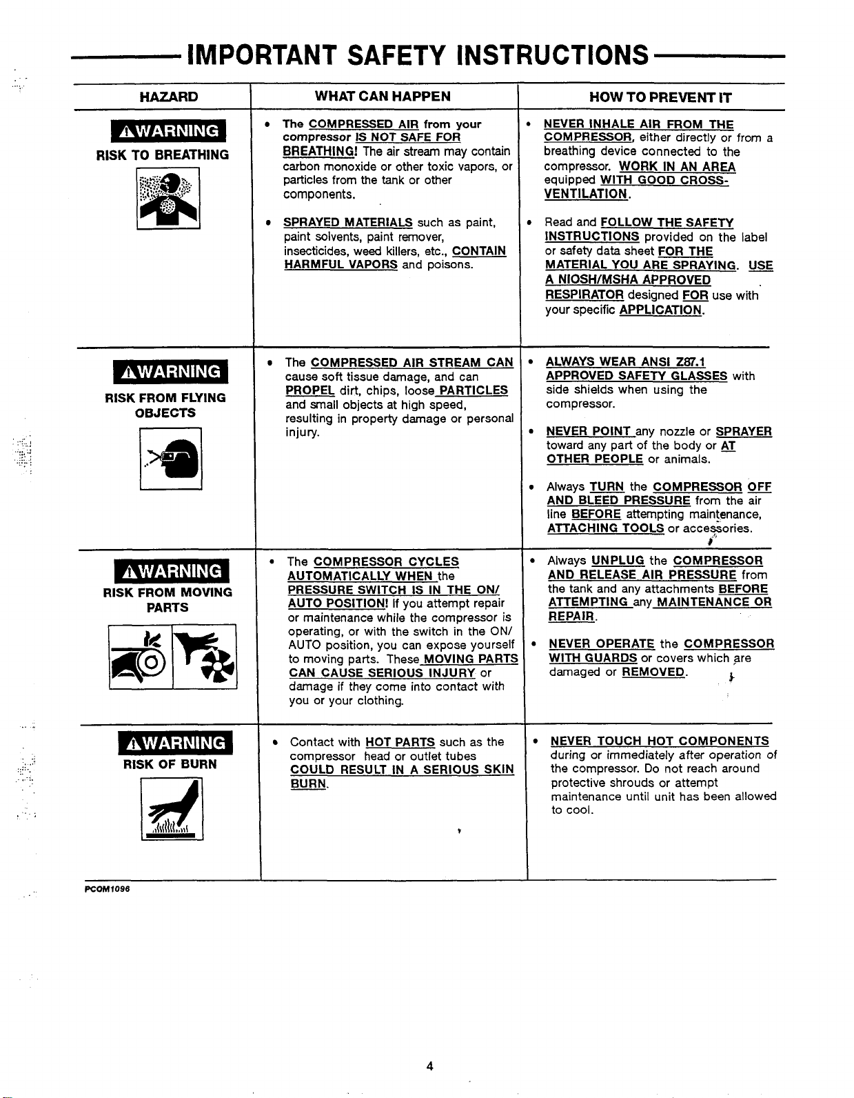
The COMPRESSED AIR
compressor
BREATHING! The air stream may contain
carbon monoxide or other toxic vapors, or
particles from the tank or other
components.
SPRAYED MATERIALS such as paint,
paint solvents, paint remover,
insecticides, weed killers, etc., CONTAIN
HARMFUL VAPORS and poisons.
The COMPRESSED AIR STREAM CAN
cause
PROPEL dirt, chips, loose PARTICLES
and small objects at high speed,
resulting in property damage or personal
injury.
The COMPRESSOR CYCLES
AUTOMATICALLY WHEN the
PRESSURE SWITCH
AUTO POSITION! If you attempt repair
l
or maintenance while the compressor is
operating, or with the switch in the
AUTO position, you can expose yourself
to moving parts. These MOVING PART:
CAN CAUSE SERIOUS INJURY or
damage
you or your clothing.
IS
NOT SAFE FOR
soft
tissue damage, and can
if
they come into contact with
from
your
IS
IN THE ON/
NEVER INHALE AIR FROM THE
COMPRESSOR, either directly or from a
breathing device connected to the
compressor. WORK
equipped WITH GOOD CROSSVENTILATION.
Read and FOLLOW THE SAFETY
INSTRUCTIONS provided on the label
or safety data sheet
MATERIAL YOU ARE SPRAYING.
A NIOSH/MSHA APPROVED
RESPIRATOR designed
your specific APPLICATION.
ALWAYS WEAR ANSI
APPROVED SAFETY GLASSES with
side shields when using the
compressor.
NEVER POINT any nozzle or SPRAYER
toward any part of the body or
OTHER PEOPLE or animals.
Always TURN the COMPRESSOR
AND BLEED PRESSURE from the air
line BEFORE attempting maintenance,
ATTACHING TOOLS or acceGories.
Always UNPLUG the COMPRESSOR
AND RELEASE AIR PRESSURE
the tank and any attachments BEFORE
ATTEMPTING any MAINTENANCE
ON/
WITH GUARDS or covers which are
HOW
TO
PREVENT
IN
FOR
IT
AN AREA
THE
USE
FOR
use with
287.1
AT
QFJ
2
from
OR
R
EPA
IR
.
NEVER OPERATE the COMPRESSOR
damaged or REMOVED.
5-
..
.,
RISK
OF
BURN
Contact with HOT PARTS such as the
compressor head or outlet tubes
COULD RESULT IN
BURN.
A
SERIOUS SKIN
t
4
NEVER TOUCH HOT COMPONENTS
during
or
the compressor. Do not reach around
protective shrouds or attempt
maintenance until unit has been allowed
to
immediately after operation
cool.
of
GLOSSARY
CFM: Cubic feet per minute.
SCFM:
Standard cubicfeet per minute; a unit of measure of
air delivery.
inch
PSIG: Pounds per square
pressure.
ASME:
tested, inspected and registered to meet
ASME.
California Code: Units comply with California Code
(Z)/(M)
tank on units that comply
Cut-In
drops as you continue to use your accessory
American Society of Mechanical Engineers; made,
(2).
Specification/model label
Pressure:
While the motor
gauge; a unit of measure
the
standards of
is
on the side of the
with
California Code.
is
off,
air tank pressure
462
of
(L)
or air tool. When the tank pressure drops
motor will restart automatically.* The pressure
motor automatically re-starts
Cut-Out Pressure: When you turn on your air compressor and
it
begins to run, air pressure in the
builds to a certain high pressure before the motor automati-
shuts
cally
than
off
U.L.
ers Laboratories, Inc. (U.L.). Samples of these products have
been evaluated by
for safety.
*See specification chart on front page.
off
its
capacity. The high pressure
is
called "cut-out pressure."
Listed: Pr0ductswiththeU.L markarelisted by Underwrit-
DUTY CYCLE
All Makita manufactured air compressors should be operated on not more than a
50%
that pumps air more than
demand. Maximum compressor pumping time per hour
of one hour
GENERAL
is
considered misuse, because the air compressor
is
30 minutes.
INFORMATION
to
a certain level the
at
which the
is
called "cut-in pressure."
air
tank begins to build.
-
protecting your air tank from pressure higher
at
which
the motor shuts
U.L.
and meet the applicable U.L standards
50%
duty cycle. This means an air compressor
is
undersized for the required air
It
This air compressor requires no oil. Now you can enjoy
purchase, add or change oil.
Your air compressor can be used for operating paint spray guns, air tools, caulking guns, grease guns, air brushy, sandblaster,
inflating tires and plastic toys, or spraying
applications.
Separate air transformers which combine the functions of air regulation and/or moisture and dirt removal should be used where
applica ble.
weed killers, insecticides, etc. An air pressure regulator
all
the benefits of having an air compressor without ever having to
-
I
is
supplied for these
ON-RECEIPT
DAMAGE: Each air compressor outfit
result in transit and cause problems
Immediately upon arrival, check equipment for both concealed and visible damages to avoid expenses being incurred to correct
such problems. This should be done regardless of any visible signs of damage to the shipping container.
shipped directly to you, report any damages to carrier and arrange for inspection of goods immediately.
DESCRIPTION
Drainvalve: Thedrainvalveis locatedatthe baseoftheair tank
and is used to drain condensation at the end of each use.
Motor Thermal Overload Protector: The electric motor has an
automatic thermal overload protector. If the motor overheats for
any
reason,thethermaloverload
The motor must be allowed to
-
ONlAUTO
automatic power to the pressure switch and
power at the end
Air Intake Filter: This filter is designed to clean air coming into
the pump. This filter must alwavs be clean and free from
obstructions. See "Maintenance".
OFF Switch: Turn this switch
of
each use.
cool
is
carefully tested and checked before shipment. With improper handling, dahage may
in
compressor operation.
protectorwillshutoff themotor.
before restarting.
ON
to provide
OFF
to
remove
L
,!
If
this
product was
OF
OPERATION
Air Compressor Pump: To compress air, the piston moves Up
and down in the cylinder. On the downstroke, air is drawn in
through the air intake valve. The exhaust valve remains closed.
On the upstrokeofthe piston, airiscompressed. Theintakevalve
closes and compressed air is forced out through the exhaust
valve, through theoutlettube, through thecheckvalve and into the
air tank. Working air
raised the airtank pressure above that required at the air outlet.
Checkvalve: When the air compressor
valve is "open", allowing compressed air to enter the air tank.
When the air compressor reaches "cut-out" pressure, the check
valve "closes", allowing air pressure to remain inside the airtank.
is
not available until the compressor has
is
operating, the check
5
continued
rt
DESCRIPTION
OF
OPERATION
(cont'd)
PreSsureReleaseValve: The pressure releasevalve locatedon
the side of the pressure switch, is designed to automatically
releasecompressed airfrom thecompressor head andtheoutlet
tube when the air compressor reaches "cut-out" pressure or is
shut
off.
If the air is not released, the motor
be unable
restart freely.
escaping from this Valve for a
heard leaking when the motor is running, or continuous leaking
after unit reaches cut-out pressure.
Pressure Switch: The pressure switch automatically starts the
motorwhen the air tank pressuredrops below the factory set"cutin" pressure.
reaches the factory set "cut-out" pressure.
Safety Valve: If the pressure switch does not shut
compressor at
protect against high pressure by "popping out" at its factory set
pressure (slightly higherthan the pressure switchcut-outsetting).
-
location
Locate the air compressor in a clean, dry and well ventilated
area. The air filter must be kept clear of obstructions which could
reduce air delivery of the air compressor. The air compressor
should be located at least
obstructions that will interfere with the flow
compressor head and shroud are designed to allow for proper
cooling. If humidity is high, an air filter can be installed on the
air outlet adapter to remove excessive moisture. Follow the
instructions packaged with the air filter for proper installation.
Lubrication and
This unit needs no lubrication or oiling.
to.
The pressure release valve allows the motor to
When
the
motor
stops
few
It
stops the motor when the air tank pressure
its
cut-out pressure setting, the safety valve will
INSTALLATION
of
the Air Compressor
12"
Oil
will
try
to start, but
running,
seconds. No air should be
air
will
AND
away from the wall or other
of
air. The air
will
be
heard
off
the air
BREAK-IN
Outlet Pressure Gauge: The outlet pressure gauge indicates
the air pressure available at the outlet side of the regulator. This
pressure is controlled bythe regulatorand is always lessorequal
to the tank pressure. See "Operating Procedures".
Tank Pressure Gauge: The tank pressure gauge indicates the
reserve air pressure in the tank.
Regulator:
trolled bythe regulatorknob.Turn the knobclockwiseto increase
pressure and counterclockwise to decrease pressure. To avoid
minor readjustment after making a change in pressure setting,
always approach the desired pressure from a lower pressure.
When reducing from a higher to a lower setting, first reduce to
some
pressure. Depending on the air requirements of each particular
accessory, the outlet regulated air pressure may have to be
adjusted while you are operating the accessory.
The air pressure coming from the air tank
pressurelessthanthatdesired,
then bring uptothedesired
PROCEDURES
is
con-
-
Piping (cont'd)
If
a pipe line is necessary, use pipe that is the same size as the
air tank outlet. Piping that is too small will restrict the flow of air.
If
piping is over
underground lines below the frost line and avoid pockets where
condensation can gather and freeze. Apply pres;ure before
underground lines are covered to make sure all pipe joints are
free of leaks.
GROUNDING INSTRUCTION
100
feet long, use the next larger size. Bury
.. ..
Extension Cords
To avoid voltage drop, power loss, and overheating of the
motor, use an extra air hose instead of an extension cord.
Low voltage can cause damage to the motor.
If
an extension cord mustbe used:
use only a 3-wire extension cord that has a 3-blade grounding plug and a 3-slot receptacle that will accept the plug on
the air compressor.
make sure the extension cord is in good condition.
the extension cord should be no longerthan 50feet.
the minimum wire size
increases as gauge number decreases.
may
also
be used.
is
12 gauge (AWG). (Wire size
DO
NOT
USE
14
AWG or
10
AWG and 8 AWG
16
AWG.)
Piping
is
Plastic or PVC pipe
compressed air. Regardless of its indicated
pressure rating, plastic pipe can burst from air
pressure, Use only metal pipe for air distribution
lines.
not designed for use with
RISK
OF
ELECTRICAL SHOCK!
shortcircuit, grounding reduces the riskof shock
by providing an escape wire for the electric
current. This air compressor must be properly
grounded.
The air compressor is equipped with a cord having a grounding
wire with an appropriate grounding plug. The plug must be used
with an outletthat has been installed and grounded in accordance
all
with
sameconfiguration astheplug. Seeillustration. DONOTUSEAN
ADAPTER.
Inspect the plug and cord before each use.
there are signs
6.
local codes and ordinances. The outlet must have the
of
damage.
IMPROPER GROUNDING CAN RESULT IN
ELECTRICAL SHOCK.
Do not modifythe plug that has been provided.
not fit the available outlet, the correct outlet should be
installed by a qualified electrician.
In
the event ota
Do
not
If
it does
continued
use if
IC
INSTALLATION AND
BREAK-IN
PROCEDURES
(cont'd)
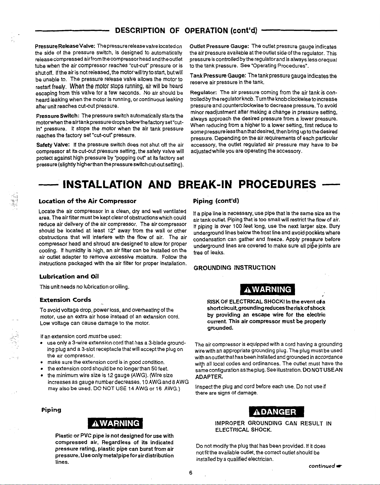
GROUNDING INSTRUCTION
If
repairing or replacing cord or plug, the grounding wire must
be kept separate from the current-carrying wires. Never connect the grounding wire to a flat blade plug terminal. The
grounding wire has insulation with an outersurface that
-
with or without yellow stripes.
If
these grounding instructions are not completely understood,
or
if
in doubt asto whetherthecompressor is properly grounded,
have the installation checked by a qualified electrician.
120
Volt
Modete
Additional Regulators and Controls
Since the air tank pressure is usually greater than that which is
needed, aseparate
pressure ahead of any individual air driven device.
Separate air transformers which combine the function
regulation, moisture and dirt removal should be used where
applicable.
regulatorisusuallyemployed
(cont'd)
240
bit
is
Models
tocontrolthe air
green
of
air
NOTE
It
is notuncommon for the airtank
water from the testing
Break4
This procedure is required:
1.
2.
3.
n
Procedures
Serious damage may result ifthe following break-
in
instructions are
Before the air compressor is put into service.
When the checkvalve is replaced.
When a complete compressor pump is replaced.
a.
Set the pressure switch lever to the
Plug the power cord into the correct branch circuit
b.
receptacle.
Turn the drain valve clockwise, opening itfully, to
c.
prevent air pressure build-up in the tank.
Move the pressure switch lever to "OWAUTO".
d.
The compressor will start.
Run the compressor for
e.
the drain valve, is open and there is
little tank pressure build-up.
After
15
f.
it
will
The compressor is now ready for use.
minutes, close the drain valve by turning
completely counterclockwise. The air rdceiver
fill
to cut-out pressure and the moty will stop.
of
the tank at the factory.
not
closely
to
contain some
followed.
15
minutes. Make sure
''OFF'' position.
OPERATING PROCEDURES
Daily
Start-up
1.
Before attaching air hose or accessories, make sure the
pressure switch lever is set to "OFF" and the air regulator
or shut-off valve is closed.
2.
Attach hose and accessories.
TOO MUCH AIR PRESSURE CAUSES A HAZARDOUS
RISK OF BURSTING. CHECK THE MANUFACTURER'S
MAXIMUM PRESSURE RATING FOR AIR TOOLS AND
ACCESSORIES. THE REGULATOR OUTLET PRES-
SURE MUST NEVER EXCEED THE MAXIMUM PRESSURE RATING.
3.
Turn the pressure switch lever to "ON/AUTO and allow
tank pressure to build. Motor will stop when tank pressure
reaches "cut-out" pressure.
4.
Open the regulator by turning it clockwise. Adjust the regulator to the correct pressure setting. Your compressor is
ready for use.
5.
Alwaysoperate the aircompressor in well-ventilated areas;
freeof gasoline orothersolventvapors. Do notoperatethe
compressor near the spray area.
Checklist
When
you
are
finished:
6.
Set the pressure switch lever
7.
Using the air
down
8.
Remove the air tool or accessory.
Drain water from air tank by opening drain valve on bottom
9.
of
tank.
WATER
IF
AND WEAKEN THE AIR TANK CAUSING A
RISK
tool
or accessory, bleed the tank pressure
to
approximately
WILL
CONDENSE IN THE AIRTANK.
NOT DRAINED, WATER WILL CORRODE
OF AIR TANK RUPTURE.
20
psi.
to
"OFF.
#
J.
NOTE
If
drain cockvalve is plugged, release all air
pressure. The valve can then be removed,
cleaned, then reinstalled.
10.
After the water has been drained, close the drain cock or
drain valve. The air compressor can now be stored.
7

MAINTENANCE
..
...
.
.
...
..
.-,
..
.
..
....
..
,:.
,
.:
.
...
.....
.
.. ..
UNIT CYCLES AUTOMATICALLY WHEN POWER
VOLTAGE SOURCES, COMPRESSED AIR OR MOVING PARTS.
PERFORMING ANY MAINTENANCE OR REPAIR, UNPLUG THE COMPRESSOR AND BLEED
SURE.
To
ensure efficient operation
followed.Thefolbwing routine
If
necessary, the schedule should be modified to suit the conditions under which your compressor is used. The modifications will
depend uponthe hours of operation and the working environment. Compressoroutfiks in an extremely dirty and/or hostile environment
will require a greater frequency of all maintenance checks. Lubricate compressor motor (if required) according
instructions, which are attached to your motor.
and
longer
lie
of
the
maintenancescheduleisgearedto
IS
ON. WHEN DOING MAINTENANCE, YOU MAY BE EXPOSED TO
air
compressor outfii, a routine maintenance schedule should be prepared and
an outfiit in a normalworking environmentoperating on adaily basis.
PERSONAL INJURIES CAN OCCUR. BEFORE
OFF
ALL AIR PRES-
to
manufacturer's
ROUTINE MAINTENANCE SCHEDULE
Daily:
1.
Drain water from the air tank, any moisture separators
or transformers.
2.
Check for any unusual noise and/or vibration. valves.
3. Manually check all safety valves
operating properly.
4.
Inspect air filter, replace
5.
Inspect air linesand fittings for leaks; correct as necessary.
if
to
make sure they are
necessary. out.
Each Year
is
Suspected:
Check condition
Check condition of check valve. Replace if damaged or worn
of
Operation or ifa Problem
of
air compressor pump intake and exhaust
SERVICE INSTRUCTIONS
Air Filter -Inspection and Replacement
Keep the air filter clean at all times.
compressor with the air filter removed.
A dirty air filter will not allow the compressor
capacity. Before you use the compressor, check the air filter to
it
is
be sure
If
it
is dirty, simply pull
Safety Valve - Inspection
IF THE SAFETY VALVE DOES NOT WORK PROP-
ERLY, OVER-PRESSURIZATION MAY OCCUR,
CAUSING AIR TANK RUPTURE OR AN EXPLOSION.
OCCASIONALLY PULL THE RING
VALVE TO MAKE SURE THAT THE SAFETY VALVE
OPERATES FREELY.
DOES NOT OPERATE SMOOTHLY, IT MUST BE
PLACED WITH THE SAME TYPE
Units
Replacement
1.
2.
3.
clean.
it
out and replace.
IF THE VALVE
With
External
Release all air pressure from air tank and unplug outfit.
Removeshroud.
Loosenthetopandbottomnutoftheoutlettubeand remove.
Brass
Do
not operate the
ON
OF
Check
to
operate at full
THE SAFETY
IS
STUCK OR
VALVE.
Valve
RE-
4.
Remove the pressure release tube and fitting.
Unscrew the check valve (turn counterclockw$e) using a
5.
socket wrench.
Check thatthe valve disc movesfreely inside the
6.
checkvalve and that the spring holds the disc in the
upper, closed position. The check valve may be cleaned
with a strong solvent.
Apply sealant to the check valve threads. Reinstall the
7.
check valve (turn clockwise).
Replace the pressure release tube and fitting.
8.
Replace the outlettube and tighten top and bottomputs.
9.
10.
Replacetheshroud.
-'
Motor
The motor has an automatic reset thermal overload protector.
the motor overheats for any reason, the overload protector will
shutoffthe motor.Themotormustbe allowedtocooldown before
restarting. The compressor will automatically restart after the
motprcoo~s.
If
the overload protector shuts the motor
for a possible voltage problem. Low voltage can
pected when:
The motor does not get up to full power or speed.
1.
Fuses blow out when starting the
2.
and remain dim when motor is started and is running.
off
frequently, check
motor;
lights dim
also
be
SUS-
If
8
STORAGE
Before you store the air compressor, make sure you do the
following:
1.
Review the “Maintenance” and ”Operating Procedures”
sections and perform maintenance as necessary. Be sure
to drain water from the air tank.
Protect the electrical cord and air hose from damage (such
2.
as being stepped on or run over), Wind them loosely around
the compressor handle.
Store the air compressor in a clean and dry location.
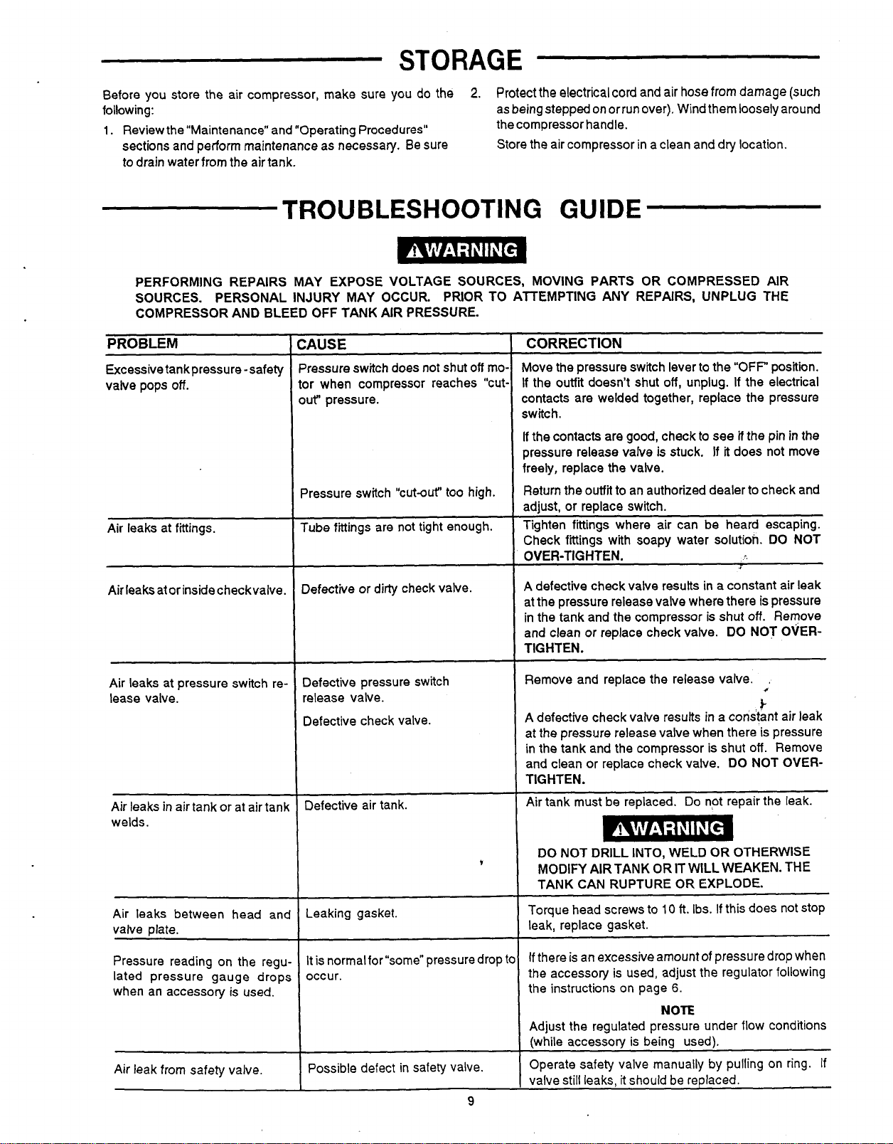
TROUBLESHOOTING
PERFORMING REPAIRS MAY EXPOSE VOLTAGE SOURCES, MOVING PARTS OR COMPRESSED AIR
SOURCES. PRIOR TO AlTEMPTING ANY REPAIRS, UNPLUG THE
COMPRESSOR AND BLEED OFF TANK AIR PRESSURE.
PROBLEM
Excessive tank pressure -safety
valve pops
Air leaks at fittings.
Air leaks ator inside checkvalve.
off.
PERSONAL INJURY MAY OCCUR.
:AWE
’ressure switch does not shut
or when compressor reaches “cut,
~t“ pressure.
Pressure switch “cut-out” too high.
Tube fittings are not tight enough.
~~ ~
lefective or dirty check valve.
off
mo.
GUIDE
CORRECTION
Move the pressure switch lever to the
If
the outfit doesn’t shut
contacts are welded together, replace the pressure
switch.
If the contacts are good, check
pressure release valve is stuck.
freely, replace the vaive.
Return the outfii to an authorized dealer to check and
adjust, or replace switch.
Tighten fittings where air can be heard escaping.
Check fittinas with soaw water solution.
OVER-TIGHTEN.
A
defective check valve resutts in a constant air leak
at the pressure release valve where there
in the tank and the compressor is shut
and clean or replace check valve.
TIGHTEN.
off,
unplug.
to
see
If
“OFF“
position.
If
the electrical
if
the pin in the
it
does not move
DO
NOT
J
is
pressure
off.
Remove
DO NOT OVER-
Air leaks at pressure switch re-
lease valve.
Air leaks in air tank or at air tank
welds.
Air leaks between head anc
valve plate.
Pressure reading on the regu
lated pressure gauge dropc
when an accessory is used.
Air leak from safety valve.
3efective pressure switch
release valve.
Defective check valve.
Defective air tank.
Leaking gasket.
is
normal for “some” pressure drop t’
It
occur.
Possible defect in safety valve.
9
Remove and replace the release valve.
.
c
&
A
defective check valve results in a constant air leak
at the pressure release valve when there is pressure
in the tank and the compressor
and clean or replace check valve.
TIGHTEN.
Air tank must be replaced.
DO
NOT DRILL INTO, WELD OR OTHERWISE
MODIFY AIR TANK OR IT WILL WEAKEN. THE
TANK CAN RUPTURE OR EXPLODE.
Torque head screws to
leak, replace gasket.
If there is an excessive amount
the accessory is used, adjust the regulator following
the instructions on page 6.
Adjust the regulated pressure under flow conditions
(while accessory is being used).
Operate safety valve manually by pulling on ring. If
valve still leaks, it should be replaced.
10
NOTE
is
shut
off.
DO NOT OVER-
Do
not repair the leak.
ft.
Ibs.
If
this does not stop
of
pressure drop when
Remove
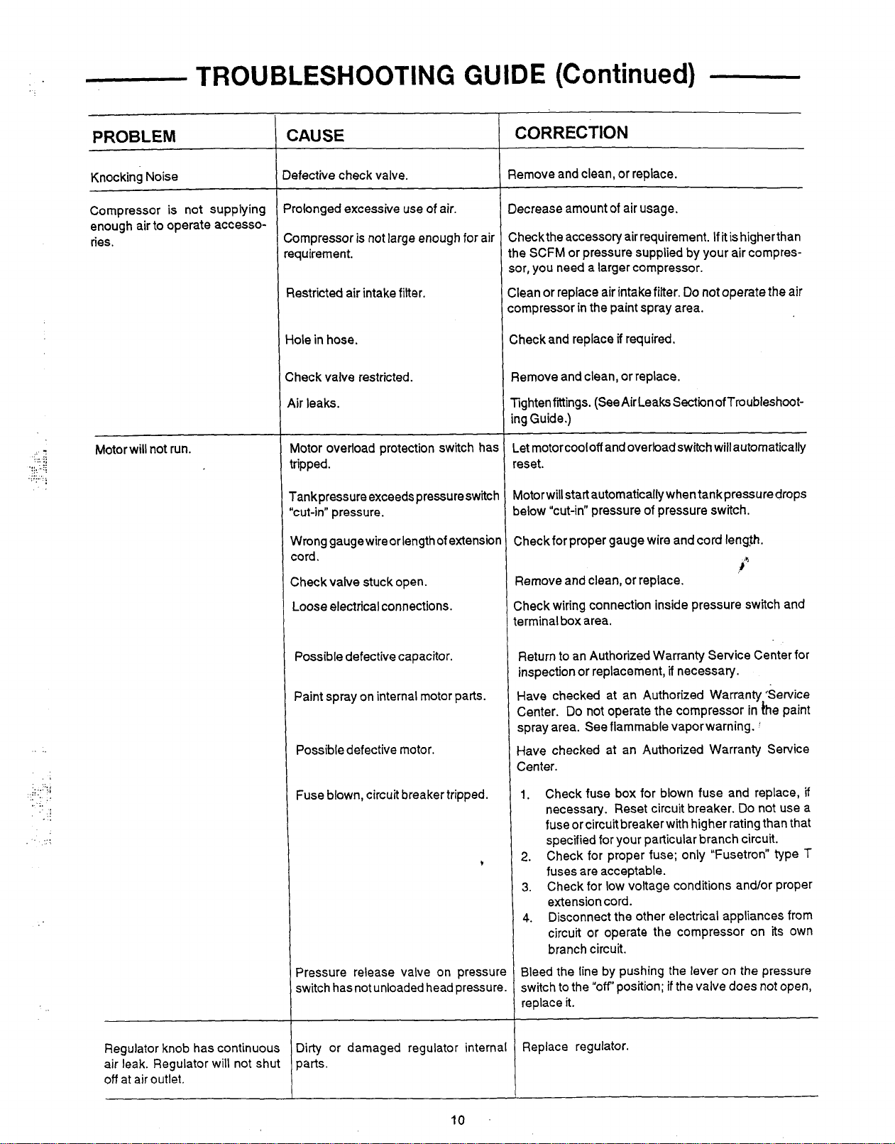
TROUBLESHOOTING
GUIDE
(Continued)
X..'
. . .
PROBLEM
Knocking Noise
Compressor is not supplying
enough air
ries.
to
operate accesso-
CAUSE
tefective check valve.
Volonged excessive use of air.
:ompressor is not large enough for air
equirement.
CORRECTION
Remove and clean, or replace.
-~
Decrease amount
of
air usage.
Checkthe accessory airrequirement.
the SCFM or pressure supplied by your air compres-
~~
If
it
is higherthan
sor, you need a larger compressor.
estricted air intake filter.
Clean or replace air intake filter.
Do
not
operate the air
compressor in the paint spray area.
ole in hose.
heck valve restricted.
,ir leaks.
Check and replace
Remove and clean, or replace.
Tightenfittings. (See Air Leaks Section ofTroubleshoot-
if required.
ing Guide.)
__
~
..
,
.
.I
...
..
..
.,
::
...
.
..
.
,
.
..
Motor will not run.
Aotor overload protection switch ha:
ripped.
'ank pressure exceeds pressure switc!
cut-in" pressure.
Nrong gaugewireorlengthof extensioi
:ord.
;heck valve stuck open.
-oose electrical connections.
Let motorcooloff and overload switch will automatically
eset.
hotorwill start automatically when tank pressure drops
ielow "cut-in" pressure of pressure switch.
;heck for proper gauge wire and cord lenah.
a"
?emove and clean, or replace.
;heck wiring connection inside pressure switch and
erminal box area.
'..,,':,[
....
..
..
1
..
..
..
Regulator knob has continuou!
will
air leak. Regulator
not shu
off at air outlet.
Possible defective capacitor.
Paint spray on internal motor parts.
Possible defective motor.
Fuse blown, circuit breaker tripped.
hessure release valve on pressur
switch has not unloaded head pressurc
Dirty or damaged regulator intern;
parts.
Return
to
an Authorized Warranty Service Center for
inspection or replacement,
if
necessary.
Have checked at an Authorized Warranty 'Service
Center.
spray area. See flammable vapor warning.
Do
not operate the compressor
in
he paint
'
Have checked at an Authorized Warranty Service
Center.
Check fuse box for blown fuse and replace,
1.
necessary. Reset circuit breaker. Do not use a
fuse or circuit breaker with higher rating than that
specified for your particular branch circuit.
Check for proper fuse; only "Fusetron" type
2.
fuses are acceptable.
Check for low voltage conditions and/or proper
3.
extension cord.
Disconnect the other electrical appliances from
4.
circuit or operate the compressor on its own
branch circuit.
Bleed the line by pushing the lever on the pressure
switch to the
"off"
position;
if
the valve does not open,
replace it.
Replace regulator.
if
T
10
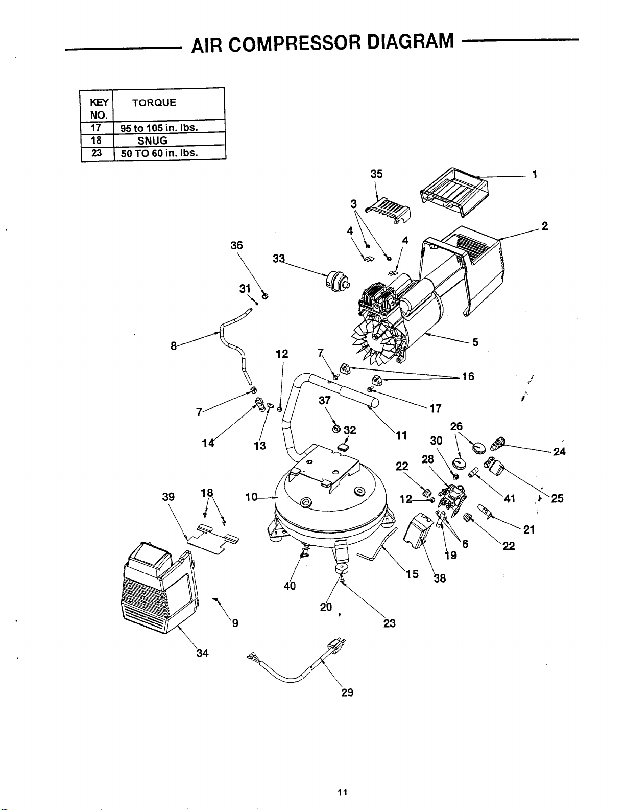
AIR
COMPRESSOR
DIAGRAM
Kf/
NO.
17
18
23
TORQUE
95
to
105
SNUG
50
TO
60
in.
in.
Ibs.
Ibs.
\
34
29
23
-
24
25
11
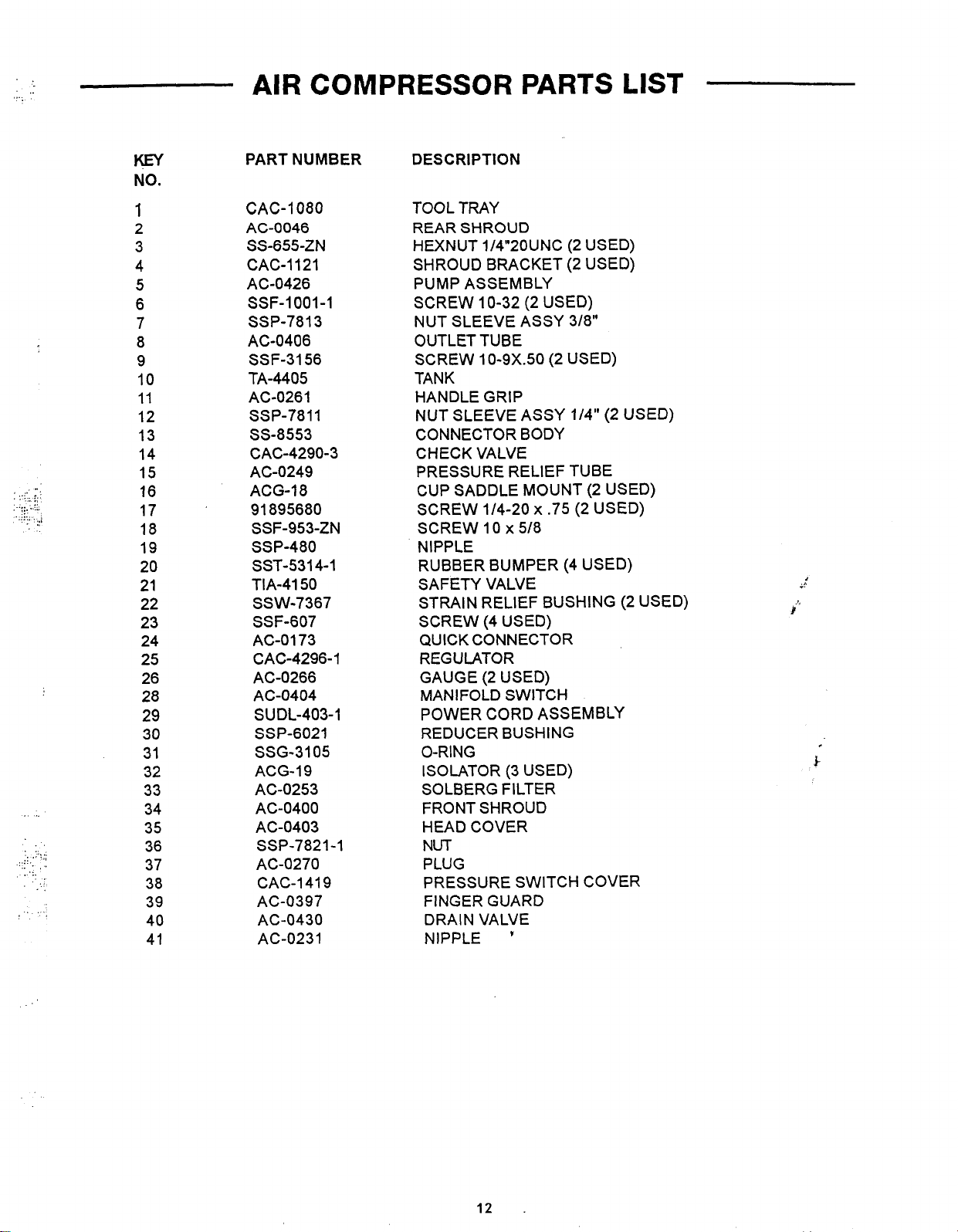
KEY
NO.
PART NUMBER DESCRIPTION
.-
,
..
.
...
..
.
.
...
...
./
_.,.
..
.
,
:.,
.....
.
.....
..... .
..
.
,.
..
1
2
3
4
5
6
7
8
9
10
11
12
13
14
15
16
17
18
19
20
21
22
23
24
25
26
28
29
30
31
32
33
34
35
36
37
38
39
40
41
CAC-1080
AC-0046
SS-655-ZN
CAC-1121
AC-0426
SSF-1001-1
SSP-7813
AC-0406
SSF-3156
TA-4405
AC-0261
SSP-7811
SS-8553
CAC-4290-3
AC-0249
ACG-18
91 895680
SSF-953-ZN
SSP-480
SST-5314-1
TIA-4150
SSW-7367
SSF-607
AGO1 73
CAC-4296-1
AC-0266
AC-0404
SUDL-403-1
SSP-6021
SSG-3105
ACG-19
AC-0253
AC-0400
AC-0403
SSP-7821-1
AC-0270
CAC-1419
AC-0397
AC-0430
AC-0231
TOOL TRAY
REAR SHROUD
HEXNUT 1/4"20UNC (2 USED)
SHROUD BRACKET (2 USED)
PUMP ASSEMBLY
SCREW 10-32 (2 USED)
NUT SLEEVE ASSY 3/8"
OUTLET TUBE
SCREW 10-9X.50 (2 USED)
TANK
HANDLE GRIP
NUT SLEEVE ASSY 1/4" (2 USED)
CONNECTOR BODY
CHECK VALVE
PRESSURE RELIEF TUBE
CUP SADDLE MOUNT (2 USED)
x
SCREW 1/4-20
SCREW 10
.75 (2 USED)
x
5/8
NIPPLE
(4
RUBBER BUMPER
USED)
SAFETY VALVE
STRAIN RELIEF BUSHING (2 USED)
SCREW (4 USED)
QUICK CONNECTOR
REGULATOR
GAUGE
(2
USED)
MANIFOLD SWITCH
POWER CORD ASSEMBLY
REDUCER BUSHING
O-RING
ISOLATOR (3 USED)
SOLBERG FILTER
FRONT SHROUD
HEAD COVER
NUT
PLUG
PRESSURE SWITCH COVER
FINGER GUARD
DRAIN VALVE
NIPPLE
'
12
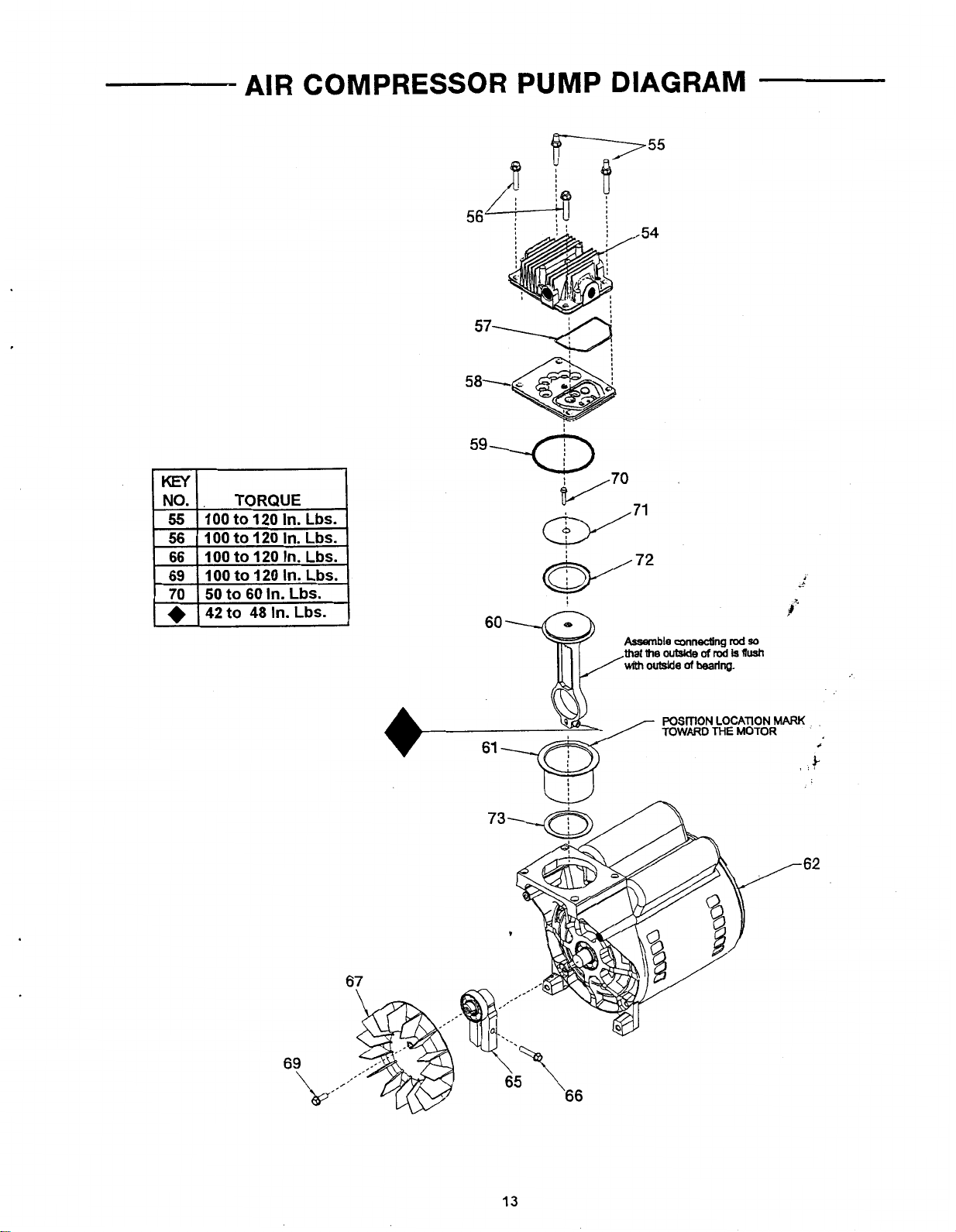
AIR
COMPRESSOR PUMP
58-
DIAGRAM
lwl
I
66 I 100
to
120
In.
Lbs.
I
59uz>
$/70
w7’
I
v7*
-62
69
67
,
65
13
\
66
..
.
..
..
....
,:.,
..... . .
.
.
,
."
AIR
COMPRESSOR
PUMP
PARTS
LIST
KEY
NO.
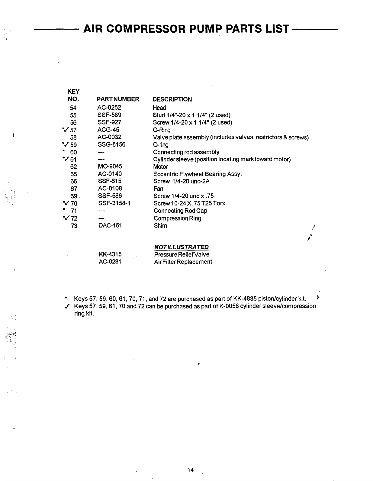
54
55
56
*J
57
58
8J
59
.'
60
*J
61
62
65
66
*J
*J
67
69,
70
71
72
73
.
,
. . .
,
..
,
.
..
.
PARTNUMBER
AC-0252
SSF-589
SSF-927
ACG-45
AC-0032
SSG-8156
---
---
Ma9045
AC-0140
SSF-615
AC-0108
SSF-586
SSF-3158-1
---
-
DAC-161
D
ESCRl
PTlO
N
Head
x
Stud 1/4"-20
Screw 1/4-20
1 1/4" (2 used)
x
1 1/4" (2 used)
CLRing
Valve plate assembly (includes valves, restrictors
&
oring
Connecting rod assembly
Cylindersleeve (position locating marktoward motor)
Motor
Eccentric Flywheel Bearing Assy.
Screw 1/4-20 unc-2A
Fan
Screw 1/4-20 unc
Screw 10-24
x
.75
X
.75 T25 Tom
Connecting Rod Cap
Compression Ring
Shim
screws)
1
..
..
...
.
..
..
.
..
.
..
..
.....
..
.
..
..
.
..
..
.
.,
. ..
..
NOTILLUSTRATED
KK-4315
AGO281
*
Keys 57,59,60,61,70,71, and 72 are purchased as part of KK-4835 piston/cylinder kit.
J
Keys 57,59,61,70 and 72 can be purchased as part of K-0058 cylinder sleeve/compression
Pressure Relief Valve
Air Filter Replacement
ring kit.
/6
14
SERVICE
NOTES
,
-
i
15
 Loading...