

Page 1
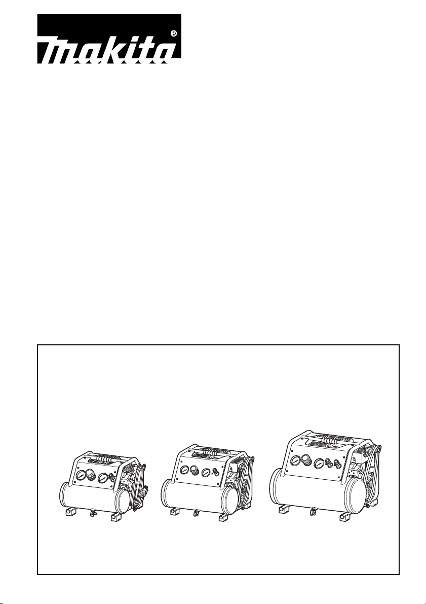
Air Compressor
Compresseur d’air
Manuel d’instructions
Compresor de aire
Manual de instrucciones
MAC100Q
MAC210Q
MAC320Q
Instruction Manual
Page 2

ENGLISH
2
1
3
6
5
7
8
9 10
11
1312
14
4
MAC100Q, MAC210Q
2
1
3
6
5
7
9 10
11
1312
14
8
4
MAC320Q
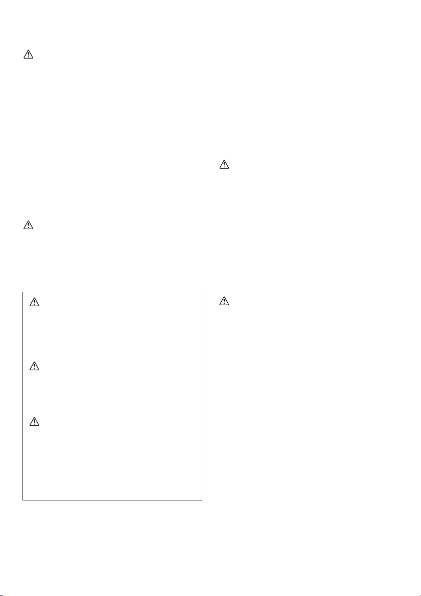
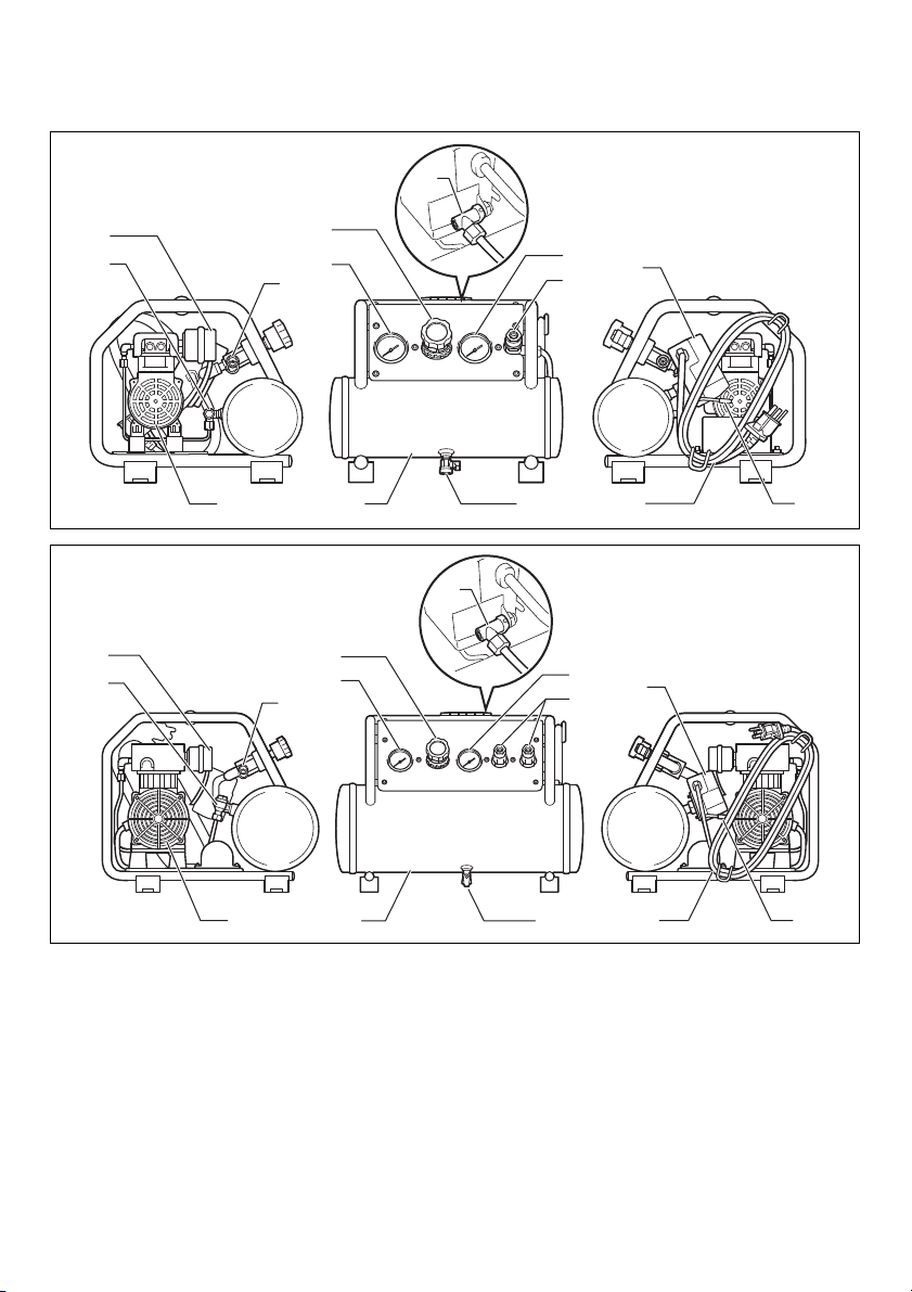
Parts description
1. Air filter (Air intake)
2. Check valve
3. Safety valve
4. Air compressor pump
5. Regulator
6. Tank pressure gauge
7. Outlet pressure gauge
Note:
The shape of the drain valve differs between MAC100Q and MAC210Q.
2
8. Quick coupler
9. Air tank
10. Drain valve
11. Pressure switch
12. Power cord
13. ON/AUTO-OFF switch
14. Pressure switch unloading valve
Page 3

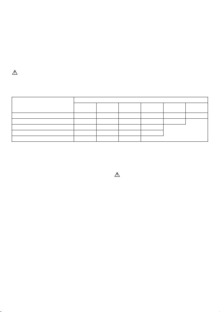
SPECIFICATIONS
Model MAC100Q MAC210Q MAC320Q
MAX Output Power 350 W 800 W 1100 W
SCFM @ 90 PSIG 0.7 2.0 2.6
Cut-In Pressure 105 PSIG (0.72 MPa)
Cut-Out Pressure 135 PSIG (0.93 MPa)
Bore x Stroke x Qty 51 mm x 8 mm x 2 64 mm x 14 mm x 2 64 mm x 17 mm x 2
Voltage -Single Phase 120 V AC
Hz 60 Hz
Motor RPM 1,750 min
Lubrication Oil-Less
Tank Size 1 gal (3.8 L) 2 gal (7.6 L) 3 gal (11.4 L)
Weight 12.5 kg (27.6 lbs) 20.5 kg (45.2 lbs) 23.8 kg (52.5 lbs)
Dimensions (L x H x W)
Outlet Max Pressure 135 PSIG (0.93 MPa)
CSA/US Listed Yes
• Due to our continuing program of research and development, the specifications herein are subject to change without
notice.
• Note: Specifications may differ from country to country.
Minimum Circuit Requirement: 15 AMPS
* A circuit breaker is preferred. Use only a fuse or circuit breaker that is the same rating as the branch circuit the air
compressor is operated on. If the air compressor is connected to a circuit protected by fuses, use time delay fuses.
L: 328 mm (12-7/8”)
W: 370 mm (14-1/2”)
H: 282 mm (11-1/8”)
L: 441 mm (17-3/8”)
W: 429 mm (16-7/8”)
H: 347 mm (13-5/8”)
IMPORTANT
Read the Safety Guidelines and ALL instructions carefully before operating.
www.makitatools.com
www.makita.ca
-1
L: 456 mm (18”)
W: 481 mm (19”)
H: 348 mm (13-3/4”)
3
Page 4
IMPORTANT SAFETY
INSTRUCTIONS
SAVE THESE INSTRUCTIONS.
WARNING
IMPROPER OPERATION OR MAINTENANCE OF THIS
PRODUCT COULD RESULT IN SERIOUS INJURY AND
PROPERTY DAMAGE.
READ AND UNDERSTAND ALL WARNINGS AND
OPERATING INSTRUCTIONS BEFORE USING THIS
EQUIPMENT.
WARNING
Risk of Unsafe Operation
WHAT CAN HAPPEN
Unsafe operation of your air compressor could lead to
serious injury to you or others.
HOW TO PREVENT IT
• Review and understand all instructions and warnings in
this manual.
• Become familiar with the operation and controls of the
air compressor.
• Keep operating area clear of all persons, pets, and
obstacles.
• Keep children away from the air compressor at all
times.
• Do not operate the product when fatigued or under the
influence of alcohol or drugs. Stay alert at all times.
• Never defeat the safety features of this product.
• Equip area of operation with a fire extinguisher.
• Do not operate machine with missing, broken, or
unauthorized parts.
WARNING
Risk of Attachments and Accessories
Bursting
WHAT CAN HAPPEN
Exceeding the pressure rating of air tools, spray guns, air
operated accessories, tires AND other inflatables can
cause them to explode or fly apart, and could result in
serious injury to you and others.
WARNING
Risk of Electric Shock
WHAT CAN HAPPEN
• Your air compressor is powered by electricity. Like any
other electrically powered device, if it is not used
properly, it may cause electrical shock.
• Electrical grounding: failure to provide adequate
grounding to this product could increase the risk of
electric shock.
HOW TO PREVENT IT
• Any electrical wiring or repairs required to this product
should be performed by qualified service personnel or
a licensed electrician, in accordance with national and
local electrical codes.
• Make certain that the electrical circuit to which the
compressor is connected provides proper electrical
grounding, correct voltage, and adequate fuse
protection.
• Never operate the compressor outdoors when it is
raining, or in a wet environment.
• Never operate the compressor with guards or covers
which are damaged or removed.
WARNING
Risk of Air Tank Bursting
WHAT CAN HAPPEN
The following conditions could lead to a weakening of the
tank, and RESULT IN A VIOLENT TANK EXPLOSION
RESULTING IN SERIOUS INJURY TO YOU OR
OTHERS:
• Failure to properly drain condensed water from the
tank, causing rust and thinning of the tank wall.
• Modifications or attempted repairs to the tank.
• Unauthorized modifications to the pressure switch,
safety valve, or any other components, which control
tank pressure.
HOW TO PREVENT IT
• Drain air tank daily or after each use. If air tank
develops a leak, replace it immediately with a new tank
or replace the entire compressor.
• Do not drill into, weld or otherwise modify air tank or it
will weaken. The tank can rupture or explode. Replace
with a new air tank.
• Follow the equipment manufacturers recommendation
and never exceed the maximum allowable pressure
rating of attachments. Never use the compressor to
inflate small low-pressure objects such as children’s
toys, footballs, basketballs, etc.
4
WARNING
Risk of Explosion or Fire
WHAT CAN HAPPEN
It is normal for electrical contacts within the motor and
pressure switch to spark, whenever the compressor starts
or stops. Never operate the compressor in an atmosphere
where flammable vapors are present. Doing so can result
in serious injury to you or others.
HOW TO PREVENT IT
• Always operate the compressor in a well-ventilated
area, free of gasoline or solvent vapors.
• If spraying flammable materials, locate compressor at
least 20 feet away from spray area.
• Store flammable materials in a secure location away
from compressor.
WARNING
Risk to Breathing
WHAT CAN HAPPEN
• The compressed air from your compressor is not safe
for breathing.
Page 5
The air stream may contain carbon monoxide or other
vapors, or particles from the tank or other components.
• Sprayed materials such as paint, paint solvents, paint
remover, insecticides, weed killers, etc., contain
harmful vapors and poisons.
• Breathing compressor or sprayed materials vapor can
result in serious injury.
HOW TO PREVENT IT
• Never inhale air from the compressor, either directly or
from a breathing device connected to the compressor.
Work in an area equipped with good cross ventilation.
• Read and follow the safety instructions provided on the
label or safety data sheet for the material you are
spraying.
Use an approved respirator designed for use with your
specific application.
WARNING: Risk from noise
Wear hearing protection to protect your ears against
exhaust noise and noise during operation.
WARNING
Risk from Compressed Air
WHAT CAN HAPPEN
The compressed air stream can cause soft tissue
damage, and can propel dirt, chips, loose particles and
small objects at high speed, resulting in property damage
or personal injury.
HOW TO PREVENT IT
• Always wear approved safety glasses with side shields
when using or maintaining the compressor.
• Never point any nozzle or sprayer toward any part of
the body or at other people or animals.
• Always turn the compressor off and bleed pressure
from the air line before attempting maintenance,
attaching tools or accessories.
WARNING
Risk from Moving Parts
WHAT CAN HAPPEN
The compressor cycles automatically when the pressure
switch is in the on/auto position. If you attempt repair or
maintenance while the compressor is operating or
plugged in, you can expose yourself to moving parts.
These moving parts can cause serious injury.
HOW TO PREVENT IT
• Always unplug the compressor and release air
pressure from the tank and any attachments before
attempting any maintenance or repair.
• Never operate the compressor with guards or covers
which are damaged or removed.
• Keep your hair, clothing, and gloves away from moving
parts. Loose clothes, jewelry, or long hair can be
caught in moving parts.
• Air vents may cover moving parts and should be
avoided as well.
WARNING
Risk of Burn
WHAT CAN HAPPEN
Contact with hot parts such as the compressor head or
outlet tubes could result in a serious skin burn.
HOW TO PREVENT IT
• Never touch hot components during or immediately
after operation of the compressor. Do not reach around
protective shrouds or attempt maintenance until unit
has been allowed to cool.
GLOSSARY
CFM: Cubic feet per minute.
SCFM: Standard cubic feet per minute; a unit of measure
of air delivery.
PSIG: Pounds per square inch gauge; a unit of measure
of pressure.
CUT-IN PRESSURE: While the motor is off, air tank
pressure drops as you continue to use your accessory or
air tool. When the tank pressure drops to a certain level
the motor will restart automatically re-started is called
“cut-in pressure”.
CUT-OUT PRESSURE: When you turn on your air
compressor, it begins to run, air pressure in the air tank
begins to build. It builds to a certain pressure before the
motor automatically shuts off - protecting your air tank
from pressure higher than its design rating. The pressure
at which the motor shuts off is called “cut-out pressure”.
DUTY CYCLE
All Makita manufactured air compressors are
recommended to be operated on not more than a 50%
duty cycle. This means an air compressor that pumps air
more than 50% in one hour is considered misuse because
the air compressor is undersized for the required air
demand.
GENERAL INFORMATION
This air compressor is equipped with an Oil-Less pump
designed for durability and no maintenance.
The compressor can be used for properly rated pneumatic
nailers and staplers. An air pressure regulator is supplied
for these applications.
WARNING
Never use compressor for applications other than to
operate a properly rated nailer or stapler. Use of the
compressor for other applications could result in property
damage and personal injury.
Separate air transformers which combine the functions of
air regulation and/or moisture and dirt removal should be
used where applicable.
ON-RECEIPT INSPECTION
DAMAGE: Each air compressor outfit is carefully tested
and checked before shipment. With improper handling,
damage may result in transit and cause problems with
compressor operation.
5
Page 6

Immediately upon arrival, check equipment for both
concealed and visible damages to avoid expenses being
incurred to correct such problems. This should be done
regardless of any visible signs of damage to the shipping
container. If this product was shipped directly to you,
report any damages to the carrier and arrange for
inspection of goods immediately.
STORAGE
Before you store the air compressor, make sure you do
the following:
1. Review the “Maintenance” and “Operating
Procedures” sections and perform maintenance as
necessary. Be sure to drain water from the air tank.
2. Protect the electrical cord and air hose from damage
(such as being stepped on or run over).
Store the air compressor in a clean and dry location.
DESCRIPTION OF OPERATION
DRAIN VALVE:
The drain valve is located at the bottom of the air tank and
is used to drain condensation at the end of each use.
AUTOMATIC SHUT OFF SYSTEM:
If the compressor automatically shuts off before reaching
its normal cutoff pressure :
1. Shut off all tools.
2. Unplug the compressor or turn off the pressure switch.
3. Wait until the compressor cools down. (about 10 min.)
4. Replug the compressor or turn on the pressure switch
to start the compressor.
5. Resume operation.
If you are using an extension cord, the compressor shuts
off even after performing above procedures. In this case,
the extension cord is too long or narrow. Replace the
extension cord with proper length and width.
ON/AUTO - OFF SWITCH:
Turn this switch to “on” to provide automatic power to the
pressure switch and to “off” to remove power when
finished using the compressor or when compressor will be
left unattended.
AIR FILTER (AIR INTAKE):
Keep the air filter clean at all times. Do not operate the
compressor with the air filter removed. The compressor
does not operate at full capacity if the air filter is dirty.
Before using the compressor, always check the air filter if
it is clean. If not, clean the air filter or replace the filter
element.
AIR COMPRESSOR PUMP:
To compress air, the piston moves up and down in the
cylinder. On the down stroke, air is drawn in through the
air intake valve. The exhaust valve remains closed.
On the upstroke of the piston, air is compressed. The
intake valve closes and compressed air is forced out
through the exhaust valve, through the outlet tube,
through the check valve and into the air tank. Useable air
is not available until the compressor has raised the air
tank pressure above that required at the air outlet.
CHECK VALVE:
When the air compressor is operating, the check valve is
“open”, allowing compressed air to enter the air tank.
When the air compressor reaches “cut-out” pressure, the
check valve “closes”, allowing air pressure to remain
inside the air tank.
PRESSURE SWITCH UNLOADING VALVE:
The pressure switch unloading valve located on the side
of the pressure switch, is designed to automatically
release compressed air from the compressor head and
the outlet tube when the air compressor reaches “cut-out”
pressure.
PRESSURE SWITCH:
The pressure switch automatically starts the motor when
the air tank pressure drops to the factory set “cut-in”
pressure. It stops the motor when the air tank pressure
reaches the factory set “cut-out” pressure.
SAFETY VALVE:
If the pressure switch does not shut off the air compressor
at its “cut-out” pressure setting, the safety valve will
protect against high pressure by “popping out” at its
factory set pressure which is slightly higher than the
pressure switch “cut-out” setting.
OUTLET PRESSURE GAUGE:
The outlet pressure gauge indicates the air pressure
available at the outlet side of the regulator. This pressure
is controlled by the regulator and is always less or equal
to the tank pressure. See “Operating Procedures”.
TANK PRESSURE GAUGE:
The tank pressure gauge indicates the air pressure in the
tank.
REGULATOR:
The air pressure coming from the air tank is controlled by
the regulator knob. Turn the knob clockwise to increase
pressure and counter-clockwise to decrease pressure. To
avoid minor re-adjustment after making a change in
pressure setting, always approach the desired pressure
from a lower pressure. When reducing from a higher to a
lower setting, first reduce to some pressure less than
desired pressure. Depending on the air requirements of
each particular accessory, the outlet regulated air
pressure may have to be adjusted while you are operating
the accessory.
COMPRESSED AIR OUTLET;
For Regular Pressure Pneumatic Tool Use
Outlet Max Pressure; 135 PSIG (0.93 MPa)
INSTALLATION AND BREAK-IN
PROCEDURES
LOCATION OF THE AIR COMPRESSOR
Locate the air compressor in a clean, dry and wellventilated area. The air filter must be kept clear of
obstructions, which could reduce air delivery of the air
compressor. The air compressor should be located at
least 12 inches away from the wall or other obstructions
6
Page 7
that will interfere with the flow of air. The air compressor
head and shroud are designed to allow for proper cooling.
If humidity is high, an air filter can be installed on the air
outlet adapter to remove excessive moisture. Follow the
instructions packaged with the air filter for proper
installation.
Place the air compressor on a flat surface so that it is
resting securely on the rubber feet.
OPERATING TEMPERATURE
The operating temperature of this compressor is between
0°C and 40°C (32°F and 104°F).
CAUTION
Never operate the compressor in the temperatures below
0°C (32°F) and above 40°C (104°F).
Please see the chart below for the MINIMUM extension cord gauge requirements:
Amp Rating Range (120 V)
0 - 5 A 161616141212
5 - 8 A 16 16 14 12 10
8 - 12 A 14 14 12 10
15 - 20 A 10 10 10
10 m
25 ft.
LUBRICATION
This air compressor is equipped with an Oil-Less pump
designed for durability and no maintenance.
Extension Cords
To avoid voltage drop, power loss, and overheating of the
motor, use extra air hose instead of an extension cord.
Low voltage can cause damage to the motor.
If an extension cord must be used:
• Use only an approved 3-wire extension cord that has a
3- blade grounding plug and a 3- slot receptacle that
will accept the plug on the air compressor.
• Make sure the extension cord is in good condition.
Total Length of Cord in Meter
15 m
50 ft.
20 m
75 ft.
30 m
100 ft.
50 m
150 ft.
Not Recommended12 - 15 A 12 12 10 10
60 m
200 ft.
Piping
Plastic or PVC pipe is not designed for use with
compressed air. Regardless of its indicated pressure
rating, plastic pipe can burst from air pressure. Use only
metal pipe for air distribution lines. If a pipe line is
necessary, use pipe that is the same size, or larger than,
the air tank outlet. Piping that is too small will restrict the
flow of air. If piping is over 100 feet long, use the next
larger size. Bury underground lines below the frost line
and avoid pockets where condensation can gather and
freeze. Apply pressure before underground lines are
covered to make sure all pipe joints are free of leaks.
Grounding Instruction
WARNING: Risk of electric shock! In the event of a short
circuit, grounding reduces the risk of shock by providing
an escape wire for the electric current. This air
compressor must be properly grounded.
The air compressor is equipped with a cord having a
grounding wire with an appropriate grounding plug. The
plug must be used with an outlet that has been installed
and grounded in accordance with all local codes and
ordinances. The outlet must have the same configuration
as the plug. DO NOT USE AN ADAPTER.
Inspect the plug and cord before each use. Do not use if
there are signs of damage.
DANGER:
Improper grounding can result in electrical shock. Do not
modify the plug that has been provided. If it does not fit
the available outlet, the correct outlet should be installed
by a qualified electrician.
OPERATING PROCEDURES
Daily Start-up Checklist
INSTALLING HOSES
WARNING
Risk of unsafe operation. Firmly grasp hose in hand
when installing or disconnecting to prevent hose
whip. Losing control of the hose may result in
personal injury and property damage.
1. Before attaching air hose or accessories, make sure
the pressure switch lever is set to “OFF” and the air
regulator or shut-off valve is closed.
2. Attach hose and accessories. Too much air pressure
causes a hazardous risk of bursting. Check the
manufacturer’s maximum pressure rating for air tools
and accessories. The regulator outlet pressure must
never exceed the maximum pressure rating.
3. Turn the pressure switch lever to “ON/AUTO” and
allow tank pressure to build. Motor will stop when tank
pressure reaches “cut-out” pressure.
4. Open the regulator by turning it clockwise. Adjust the
regulator to the correct pressure setting. Your
compressor is ready for use.
5. Always operate the air compressor in well-ventilated
areas; free of gasoline or other solvent vapors. Do not
operate the compressor near the spray area.
7
Page 8
When you are finished:
DISCONNECTING HOSES
WARNING
Risk of unsafe operation. Firmly grasp hose in hand
when installing or disconnecting to prevent hose
whip. Losing control of the hose may result in
personal injury and property damage.
6. Set the pressure switch lever to “OFF”.
7. Using the air tool or accessory, bleed the tank
pressure down to zero.
8. Remove the air tool or accessory.
9. Drain water from air tank by opening drain cock valve
on bottom of tank. WATER WILL CONDENSE IN THE
AIR TANK. IF NOT DRAINED, WATER WILL
CORRODE AND WEAKEN THE AIR TANK CAUSING
A RISK OF AIR TANK RUPTURE.
Note:
If drain valve is plugged, release all air pressure. The
valve can then be removed, cleaned, then reinstalled.
10. After the water has been drained, close the drain
valve. The air compressor can now be stored.
WARNING
Drain Air Tank Properly. Improper draining of the air
tank can result in corrosion and possible bursting of
the tank. Tank bursting could lead to personal injury
and property damage.
MAINTENANCE
WARNING:
Never use the air compressor which is operating
abnormally.
If the air compressor appears to be operating
unusually, making strange noises or vibration,
stop using it immediately and arrange for repairs
by a Makita authorized service center.
WARNING:
Use only genuine Makita replacement parts.
Replacement parts not manufactured by Makita
may void your warranty and can lead to
malfunction and result in injuries. Genuine Makita
parts are available from an authorized dealer.
WARNING:
UNIT CYCLES AUTOMATICALLY WHEN
POWER IS ON. WHEN DOING MAINTENANCE,
YOU MAY BE EXPOSED TO VOLTAGE SOURCES,
COMPRESSED AIR OR MOVING PARTS.
PERSONAL INJURIES CAN OCCUR. BEFORE
PERFORMING ANY MAINTENANCE OR REPAIR,
UNPLUG THE COMPRESSOR AND BLEED OFF
ALL AIR PRESSURE.
be prepared and followed. The following routine
maintenance schedule is geared to a unit in a normal
working environment operating on a daily basis. If
necessary, the schedule should be modified to suit the
conditions under which your compressor is used. The
modifications will depend upon the hours of operation and
the working environment. Compressor units in an
extremely dirty and/or hostile environment will require a
greater frequency of all maintenance checks.
ROUTINE MAINTENANCE SCHEDULE
1. Drain water from the air tank, any moisture separators
or transformers.
2. Check for any unusual noise and/or vibration.
3. Manually check all safety valves to make sure they are
operating properly.
WARNING: Risk of bursting.
Check Safety Valve. If safety valve does not operate
properly over pressurization of the air tank may result
in rupture or explosion causing personal injury and
property damage.
4. Inspect air filter, replace if necessary.
5. Inspect air lines and fittings for leaks; correct as
necessary.
Each year of operation or if a problem is suspected:
• Check condition of air compressor pump intake and
exhaust valves.
• Check condition of check valve. Replace if
damaged or worn out.
6. Keep all screws, bolts, and covers tightly mounted.
Check their conditions periodically.
WARNING
Keep All Screws, Bolts and Covers Properly
Tightened. If screws plates or covers become loose
personal injury or property damage may occur.
MAKITA LIMITED WARRANTY
Please refer to the annexed warranty sheet for the most
current warranty terms applicable to this product. If
annexed warranty sheet is not available, refer to the
warranty details set forth at below website for your
respective country.
United States of America: www.makitatools.com
Canada: www.makita.ca
Other countries: www.makita.com
NOTICE:
Never use gasoline, benzine, thinner, alcohol or the like.
Discoloration, deformation or cracks may result.
To ensure efficient operation and longer life of the air
compressor unit, a routine maintenance schedule should
8
Page 9
FRANÇAIS
2
1
3
6
5
7
8
9 10
11
1312
14
4
MAC100Q, MAC210Q
2
1
3
6
5
7
9 10
11
1312
14
8
4
MAC320Q
Description des pièces
1. Filtre à air (admission d’air)
2. Clapet antiretour
3. Soupape de sécurité
4. Pompe de compression d’air
5. Régulateur
6. Manomètre de réservoir
7. Manomètre de sortie
8. Raccord rapide
9. Réservoir d’air
10. Robinet de vidange
11. Manostat
12. Cordon d’alimentation
13. Interrupteur MARCHE/AUTOMATIQUE - ARRÊT
14. Valve de décompression de manostat
Remarque :
La forme du robinet de vidange des modèles MAC100Q et MAC210Q n’est pas la même.
9
Page 10

CARACTÉRISTIQUES TECHNIQUES
Modèle MAC100Q MAC210Q MAC320Q
Puissance de sortie MAX 350 W 800 W 1 100 W
3
Pi
/min std @ 90 PSIG 0,7 2,0 2,6
Pression d’enclenchement 105 PSIG (0,72 MPa)
Pression de déclenchement 135 PSIG (0,93 MPa)
Alésage x Course x Qté 51 mm x 8 mm x 2 64 mm x 14 mm x 2 64 mm x 17 mm x 2
Tension - monophasée 120 V CA
Hz 60 Hz
Régime du moteur 1 750 min
Lubrification Sans huile
Dimension du réservoir 1 gal (3,8 L) 2 gal (7,6 L) 3 gal (11,4 L)
Poids 12,5 kg (27,6 livres) 20,5 kg (45,2 livres) 23,8 kg (52,5 livres)
Dimensions (L x H x P)
Pression maximale de la sortie 135 PSIG (0,93 MPa)
Répertorié par CSA/US Oui
• Étant donné l’évolution constante de notre programme de recherche et de développement, les caractéristiques
techniques contenues dans ce manuel sont modifiables sans préavis.
• Remarque : Les caractéristiques techniques peuvent varier suivant les pays.
Exigences minimales pour le circuit : 15 ampères
* La présence d’un disjoncteur est recommandée. Utiliser uniquement un fusible ou un disjoncteur ayant la même valeur
nominale que celle du circuit de dérivation avec lequel le compresseur d’air est alimenté. Si le compresseur d’air est
branché à un circuit protégé par des fusibles, utiliser des fusibles temporisés.
L : 328 mm (12-7/8 po)
P : 370 mm (14-1/2 po)
H : 282 mm (11-1/8 po)
L : 441 mm (17-3/8 po)
P : 429 mm (16-7/8 po)
H : 347 mm (13-5/8 po)
IMPORTANT
Lire attentivement les recommandations de sécurité et TOUTES les instructions avant d’utiliser l’appareil.
www.makitatools.com
www.makita.ca
-1
L : 456 mm (18 po)
P : 481 mm (19 po)
H : 348 mm (13-3/4 po)
10
Page 11

CONSIGNES DE SÉCURITÉ
IMPORTANTES
CONSERVEZ LES PRÉSENTES
INSTRUCTIONS.
AVERTISSEMENT
UNE UTILISATION OU UN ENTRETIEN INADÉQUAT
DE CE PRODUIT PEUT ENTRAÎNER DES BLESSURES
GRAVES ET DES DOMMAGES MATÉRIELS.
S’ASSURER DE LIRE ET DE COMPRENDRE
L’ENSEMBLE DES AVERTISSEMENTS ET DES
INSTRUCTIONS D’UTILISATION AVANT D’UTILISER
CET ÉQUIPEMENT.
AVERTISSEMENT
Risques associés à une utilisation non
sécuritaire
CE QUI PEUT SE PRODUIRE
Une utilisation non sécuritaire de votre compresseur d’air
peut entraîner des blessures graves.
COMMENT L’ÉVITER
• S’assurer de consulter et de comprendre l’ensemble
des instructions et des avertissements contenus dans
le présent manuel.
• Se familiariser avec le fonctionnement et les
commandes du compresseur d’air.
• S’assurer que toute personne, tout animal ou tout
obstacle se trouve à l’écart de la zone de travail.
• Les enfants doivent se tenir à l’écart du compresseur
d’air en tout temps.
• Ne pas utiliser ce produit lorsque vous êtes fatigué ou
sous l’influence de l’alcool ou de la drogue. Toujours
rester vigilant.
• Ne jamais contourner les dispositifs de sécurité de ce
produit.
• Un extincteur doit être installé dans la zone
d’utilisation.
• Ne pas utiliser l’appareil si des pièces sont
manquantes, brisées, ou en présence de pièces non
homologuées.
AVERTISSEMENT
Risque d’éclatement du réservoir d’air
comprimé
CE QUI PEUT SE PRODUIRE
Les situations suivantes peuvent mener à un
affaiblissement du réservoir et PROVOQUER UNE
VIOLENTE EXPLOSION DU RÉSERVOIR, CE QUI
ENTRAÎNERAIT DES BLESSURES GRAVES :
• Ne pas vidanger correctement l’eau condensée dans le
réservoir, ce qui cause la corrosion et l’amincissement
de la paroi du réservoir.
• Toute modification ou tentative de réparations
effectuées sur le réservoir.
• Toute modification non autorisée du manostat, de la
soupape de sécurité ou de tout autre composant qui
contrôle la pression du réservoir.
COMMENT L’ÉVITER
• Vidanger le réservoir d’air quotidiennement ou après
chaque utilisation. Si le réservoir d’air présente une
fuite, le remplacer immédiatement par un nouveau
réservoir ou remplacer le compresseur au complet.
• S’abstenir de percer un trou dans le réservoir d’air, de
souder ce dernier ou de le modifier de quelque façon
que ce soit; cela l’affaiblirait. Le réservoir pourrait se
rompre ou exploser. Remplacer par un nouveau
réservoir d’air.
• Suivre les recommandations du fabricant des appareils
et ne jamais excéder la pression nominale maximale
autorisée pour les accessoires. Ne jamais utiliser le
compresseur pour gonfler de petits objets ayant une
faible pression comme les jouets pour enfants, les
ballons de soccer, les ballons de basketball, etc.
AVERTISSEMENT
Risque d’éclatement de l’équipement
et des accessoires
CE QUI PEUT SE PRODUIRE
Si la pression nominale des outils pneumatiques, pistolets
de pulvérisation, accessoires à commande pneumatique,
pneus ET autres objets gonflables est dépassée, il est
possible qu’ils explosent ou volent en éclats, ce qui peut
entraîner des blessures graves.
AVERTISSEMENT
Risque de décharge électrique
CE QUI PEUT SE PRODUIRE
• Votre compresseur d’air est alimenté par de
l’électricité. Comme tout autre appareil électrique, s’il
n’est pas utilisé correctement, il peut causer une
décharge électrique.
• Mise à la terre : si une mise à la terre adéquate n’est
pas réalisée, le risque de décharge électrique est
accru.
COMMENT L’ÉVITER
• Tout câblage électrique ou toute réparation pour ce
produit doit être réalisé par un technicien qualifié ou un
électricien agréé, conformément aux codes électriques
nationaux et locaux.
• S’assurer que le circuit électrique auquel le
compresseur est branché offre une mise à la terre
électrique correcte, une tension appropriée et une
protection par fusible adéquate.
• Ne jamais faire fonctionner le compresseur à l’extérieur
lorsqu’il pleut, ou dans un environnement humide.
• Ne jamais faire fonctionner le compresseur si les
dispositifs de protection ou les couvercles sont enlevés
ou endommagés.
AVERTISSEMENT
Risque d’explosion ou
d’incendie
CE QUI PEUT SE PRODUIRE
Il est normal que des contacts électriques dans le moteur
et le manostat produisent une étincelle lorsque le
11
Page 12

compresseur démarre ou s’arrête. Ne jamais faire
fonctionner le compresseur dans une atmosphère où sont
présentes des vapeurs inflammables. Cela pourrait
entraîner des blessures graves.
COMMENT L’ÉVITER
• Toujours utiliser le compresseur dans une zone bien
aérée, sans essence ou vapeurs de solvants.
• Si des matières inflammables sont pulvérisées, placer
le compresseur à une distance d’au moins 6,1 m
(20 pi) de la zone de projection.
• Entreposer les matières inflammables en lieu sûr, à
l’écart du compresseur.
AVERTISSEMENT
Risques respiratoires
CE QUI PEUT SE PRODUIRE
• Il est dangereux de respirer l’air comprimé sortant du
compresseur.
Le flux d’air peut contenir du monoxyde de carbone,
d’autres gaz ou des particules provenant du réservoir
ou d’autres composants.
• Les matériaux vaporisés comme la peinture, les
solvants de peinture, les décapants, les insecticides,
les herbicides, etc. contiennent des vapeurs nocives et
sont toxiques.
• L’inhalation du flux du compresseur ou des vapeurs
des matières pulvérisées peut entraîner des blessures
graves.
COMMENT L’ÉVITER
• Ne jamais inhaler l’air provenant du compresseur, que
ce soit directement ou par l’entremise d’un appareil de
ventilation branché au compresseur. Travailler dans un
endroit doté d’une bonne aération transversale.
• Lire et respecter les instructions de sécurité fournies
sur l’étiquette ou la fiche technique santé-sécurité du
produit pulvérisé.
Utiliser un respirateur homologué et conçu pour cette
application en particulier.
AVERTISSEMENT: Risques associés au
bruit
Porter un dispositif de protection de l’ouïe pour protéger
vos oreilles contre le bruit de l’échappement et le bruit
durant le fonctionnement.
AVERTISSEMENT
Risques associés à l’air comprimé
CE QUI PEUT SE PRODUIRE
Le flux d’air comprimé peut endommager les tissus mous
de la peau et peut projeter de la poussière, des
fragments, des particules détachées et des petits objets à
haute vitesse, ce qui pourrait entraîner des dommages
matériels ou des blessures.
COMMENT L’ÉVITER
• Toujours utiliser des lunettes de sécurité homologuées
munies d’écrans latéraux durant l’utilisation ou
l’entretien du compresseur.
• Ne jamais diriger la buse ou le pulvérisateur vers une
partie du corps ou vers une autre personne ou un
animal.
• Toujours mettre le compresseur hors tension et
évacuer la pression de la canalisation d’air avant
d’effectuer l’entretien ou encore de fixer des outils ou
des accessoires.
AVERTISSEMENT
Risques associés aux pièces
mobiles
CE QUI PEUT SE PRODUIRE
Le compresseur se met automatiquement en marche
lorsque le manostat est à la position marche/automatique.
S’il tente de réaliser une réparation ou un entretien
pendant que le compresseur fonctionne ou qu’il est
branché, l’utilisateur risque de s’exposer aux pièces
mobiles. Ces pièces mobiles peuvent causer des
blessures graves.
COMMENT L’ÉVITER
• Toujours débrancher le compresseur et évacuer la
pression d’air du réservoir et de tout équipement avant
d’effectuer l’entretien ou la réparation.
• Ne jamais faire fonctionner le compresseur si les
dispositifs de protection ou les couvercles sont enlevés
ou endommagés.
• Gardez vos cheveux, vos vêtements et vos gants à
distance des pièces mobiles. Des vêtements amples,
des bijoux ou de longs cheveux peuvent se prendre
dans les pièces mobiles.
• Les évents peuvent camoufler des pièces mobiles; il
convient donc de s’en tenir à l’écart aussi.
AVERTISSEMENT
Risque de brûlure
CE QUI PEUT SE PRODUIRE
Tout contact avec les pièces chaudes, comme la tête du
compresseur ou la tubulure d’échappement, peut
entraîner de graves brûlures.
COMMENT L’ÉVITER
• Ne jamais toucher les pièces chaudes pendant ou
immédiatement après l’utilisation du compresseur. Ne
pas toucher aux déflecteurs de protection ni effectuer
des réparations avant le refroidissement de l’appareil.
GLOSSAIRE
Pi³/min : pied cube par minute.
Pi³/min standard : pied cube standard par minute; une
unité de mesure du débit de l’air.
PSIG : Pression manométrique en livres par pouce carré;
une unité de mesure de la pression.
PRESSION DE RÉALIMENTATION : Quand le moteur est
arrêté, la pression du réservoir d’air chute pendant que
vous continuez à utiliser votre accessoire ou outil
pneumatique. Lorsque la pression du réservoir d’air chute
sous un certain niveau, le moteur redémarre
12
Page 13

automatiquement. C’est ce qu’on appelle la « pression de
réalimentation ».
PRESSION DE COUPURE : Lorsque vous démarrez le
compresseur d’air, il commence à fonctionner et la
pression du réservoir d’air commence à augmenter. Elle
augmente jusqu’à un certain niveau, puis le moteur
s’arrête automatiquement - ce qui évite que le réservoir
d’air soit soumis à une pression supérieure à celle pour
laquelle il a été conçu. La pression à laquelle le moteur
s’arrête est appelée « pression de coupure ».
CYCLE DE TRAVAIL
Tout compresseur fabriqué par Makita devrait être utilisé à
moins de 50 % du cycle de travail. Ainsi, si le
compresseur d’air pompe l’air pendant plus de 50 % du
temps pendant une heure d’utilisation, on considère qu’il
s’agit d’une mauvaise utilisation; le compresseur d’air est
insuffisant pour la demande d’air requise.
INFORMATIONS GÉNÉRALES
Ce compresseur d’air est doté d’une pompe sans huile,
conçue pour être durable sans nécessiter d’entretien.
Le compresseur peut être utilisé avec des cloueuses et
agrafeuses pneumatiques correctement calibrées. Un
régulateur de pression d’air est fourni pour ces
applications.
AVERTISSEMENT
Ne jamais utiliser un compresseur pour des applications
autres que l’utilisation de cloueuses ou agrafeuses
correctement calibrées. L’utilisation du compresseur pour
d’autres applications peut entraîner des dommages
matériels et des blessures.
Des transformateurs d’air distincts combinant des
fonctions de réglage d’air et/ou d’enlèvement de la saleté
et de l’humidité peuvent être utilisés le cas échéant.
INSPECTION À LA RÉCEPTION
DOMMAGES : Chaque ensemble compresseur d’air est
soigneusement testé et vérifié avant l’expédition. Il est
toutefois possible qu’une manutention incorrecte
provoque des dommages durant le transport et entraîne
des problèmes de fonctionnement du compresseur.
Dès l’arrivée de l’équipement, vérifier la présence de
dommages cachés ou visibles, afin d’éviter les dépenses
associées à la correction de tels problèmes. Cette
opération doit être effectuée même si l’emballage de
l’expédition ne présente aucun signe visible de
dommages. Si ce produit a été envoyé directement,
signaler les dommages au transporteur et prévoir
immédiatement une inspection du produit.
ENTREPOSAGE
Avant l’entreposage du compresseur d’air, s’assurer de
prendre les mesures suivantes :
1. Passer en revue les sections « Entretien » et
« Consignes d’utilisation » et réaliser les opérations
d’entretien nécessaires. Bien s’assurer de vidanger
l’eau du réservoir d’air.
2. Protéger le cordon électrique et le tuyau à air contre
les dommages (pour éviter qu’on y trébuche ou qu’on
marche dessus).
Entreposer le compresseur d’air dans un endroit propre et
sec.
DESCRIPTION DU FONCTIONNEMENT
ROBINET DE VIDANGE :
Le robinet de vidange est situé au bas du réservoir d’air. Il
est utilisé pour vidanger la condensation après chaque
utilisation.
SYSTÈME D’ARRÊT AUTOMATIQUE :
Si le compresseur s’arrête automatiquement avant
d’atteindre sa pression de coupure normale :
1. Éteindre l’ensemble des outils.
2. Débrancher le compresseur ou désactiver le
manostat.
3. Laisser le compresseur se refroidir (environ 10 min.)
4. Rebrancher le compresseur ou activer le manostat
pour faire démarrer le compresseur.
5. Reprendre le travail.
Si vous utilisez un cordon prolongateur, le compresseur
peut s’éteindre même après la réalisation des procédures
ci-dessus. Si tel est le cas, le cordon prolongateur est trop
long ou trop étroit. Remplacer le cordon prolongateur
avec un autre, de la longueur et largeur adéquate.
INTERRUPTEUR MARCHE/
AUTOMATIQUE - ARRÊT :
Mettre cet interrupteur à la position Marche (On) afin de
fournir automatiquement l’alimentation au manostat et à
Arrêt (Off) pour retirer l’alimentation lorsque vous avez
terminé d’utiliser le compresseur ou lorsque le
compresseur sera laissé sans surveillance.
FILTRE À AIR (ADMISSION D’AIR) :
Le filtre à air doit être propre en tout temps. Ne pas mettre
le compresseur en marche quand le filtre à air n’est pas
en place. Le compresseur ne fonctionne pas au maximum
de sa capacité si le filtre à air est sale. Avant d’utiliser le
compresseur, vérifier toujours si le filtre à air est propre.
Dans le cas contraire, nettoyer le filtre à air ou remplacer
l’élément filtrant.
POMPE DE COMPRESSION D’AIR :
Pour comprimer l’air, le piston se déplace vers le haut et
vers le bas du cylindre. Dans la course vers le bas, l’air
est aspiré par la soupape d’admission d’air. La soupape
d’échappement demeure fermée.
Dans la course du piston vers le haut, l’air est comprimé.
La soupape d’admission se ferme et l’air comprimé est
poussé à travers la soupape d’échappement, dans la
tubulure d’échappement jusqu’au clapet antiretour et
enfin dans le réservoir d’air. L’air utilisable n’est pas
disponible tant que le compresseur n’a pas augmenté la
pression du réservoir d’air au-delà de la pression requise
à la sortie d’air.
CLAPET ANTIRETOUR :
Quand le compresseur d’air est en fonction, le clapet
antiretour est « ouvert » et permet à l’air compressé de
13
Page 14

pénétrer dans le réservoir d’air. Lorsque le compresseur
d’air atteint la pression de « coupure », le clapet antiretour
se « ferme», ce qui permet à la pression d’air de
demeurer à l’intérieur du réservoir d’air.
VALVE DE DÉCOMPRESSION DE
MANOSTAT:
La valve de décompression de manostat, située sur le
côté du manostat, est conçue pour libérer
automatiquement l’air comprimé de la tête du
compresseur et de la tubulure d’échappement lorsque l’air
comprimé atteint la pression de « coupure ».
MANOSTAT:
Le manostat démarre automatiquement le moteur lorsque
la pression du réservoir d’air descend au-dessous de la
« pression de réalimentation ». Il arrête le moteur lorsque
la pression du réservoir d’air atteint la pression de
« coupure ».
SOUPAPE DE SÉCURITÉ :
Si le manostat n’arrête pas le compresseur d’air lorsque la
pression de « coupure » réglée est atteinte, la soupape
de sécurité protègera le réservoir contre la haute pression
en se « déclenchant » quand la pression définie en usine
sera atteinte (cette pression est légèrement supérieure à
la pression de « coupure » du manostat).
MANOMÈTRE DE SORTIE :
Le manomètre de sortie indique la pression d’air
disponible du côté de la sortie du régulateur. Cette
pression est contrôlée par le régulateur et est toujours
inférieure ou égale à la pression du réservoir. Consulter la
section « Consignes d’utilisation ».
MANOMÈTRE DE RÉSERVOIR :
Le manomètre de réservoir indique la pression de l’air
dans le réservoir.
RÉGULATEUR :
La pression de l’air provenant du réservoir d’air est réglée
à l’aide du bouton du régulateur. Tourner le bouton dans
le sens des aiguilles d’une montre pour augmenter la
pression, et dans le sens inverse pour la diminuer. Afin
d’éviter de devoir procéder à des réajustements mineurs
après avoir effectué un changement du réglage de la
pression, il faut toujours approcher la pression souhaitée
à partir d’une pression inférieure. Pour diminuer le réglage
de la pression, depuis un réglage supérieur vers un
réglage inférieur, commencer par réduire la valeur à une
pression inférieure à celle souhaitée. Selon les exigences
de chaque accessoire particulier, la pression d’air réglée à
la sortie pourrait devoir être ajustée pendant que
l’accessoire est en fonction.
SORTIE D’AIR COMPRIMÉ;
À utiliser avec les outils pneumatiques à pression
régulière
Pression maximale de la sortie; 135 PSIG (0,93 MPa)
PROCÉDURES D’INSTALLATION
ET DE RODAGE
EMPLACEMENT DU COMPRESSEUR
D’AIR
Placer le compresseur dans un endroit propre, sec et bien
aéré. Le filtre à air doit être libre d’obstruction pouvant
réduire l’approvisionnement de l’air dans le compresseur
d’air. Le compresseur d’air doit être placé à une distance
d’au moins 12 po (30,4 cm) du mur ou d’autres
obstructions qui pourraient entraver le débit de l’air. La
tête et le déflecteur du compresseur d’air sont conçus
pour permettre un refroidissement adéquat. Si le taux
d’humidité est élevé, il est possible d’installer un filtre à air
sur l’adaptateur de sortie d’air pour éliminer l’humidité
excessive. Suivre les instructions incluses dans
l’emballage du filtre à air pour une installation adéquate.
Placer le compresseur d’air sur une surface plane afin
qu’il soit solidement installé sur ses pieds de caoutchouc.
TEMPÉRATURE DE
FONCTIONNEMENT
Ce compresseur a une température de fonctionnement de
0 °C à 40 °C (32 °F à 104 °F).
ATT ENTI ON
Ne jamais faire fonctionner le compresseur si la
température est inférieure à 0 °C (32 °F) ou supérieure à
40 °C (104 °F).
LUBRIFICATION
Ce compresseur d’air est doté d’une pompe sans huile,
conçue pour être durable sans nécessiter d’entretien.
Cordons prolongateurs
Pour éviter les chutes de tension, pertes de puissance ou
surchauffes du moteur, utiliser un tuyau à air
supplémentaire au lieu d’un cordon prolongateur. Une
basse tension peut endommager le moteur.
Si l’utilisation d’un cordon prolongateur est requise :
• Utiliser uniquement un cordon prolongateur homologué
à trois fils, doté d’une fiche de mise à la terre à trois
broches, ainsi qu’une prise de courant à trois
ouvertures dans laquelle brancher cette fiche.
• S’assurer que le cordon prolongateur est en bon état.
14
Page 15

Consulter le tableau ci-dessous pour connaître les exigences MINIMALES relatives au cordon prolongateur :
Valeurs nominales en ampères -
plage (120 V)
0 à 5 A 16 16 16 14 12 12
5 à 8 A 16 16 14 12 10
8 à 12 A 14 14 12 10
15 à 20 A 10 10 10
10 m
25 pi
Longueur totale du cordon en mètres
15 m
50 pi
20 m
75 pi
30 m
100 pi
50 m
150 pi
Non recommandé12 à 15 A 12 12 10 10
60 m
200 pi
Tuyauterie
Les tuyaux de plastique ou de PVC ne sont pas conçus
pour être utilisés avec l’air comprimé. Quelle que soit la
pression nominale indiquée, les tuyaux de plastique
peuvent éclater sous la pression de l’air. Utiliser
uniquement des tuyaux métalliques pour les conduites de
distribution d’air. Si une conduite est nécessaire, utiliser
un tuyau de la même dimension que la sortie du réservoir
d’air, ou d’une dimension supérieure. Si la canalisation est
trop petite, le flux de l’air sera entravé. Si la longueur de la
canalisation est supérieure à 100 pieds (30,5 m), utiliser
la grandeur immédiatement supérieure. Enterrer les
conduites souterraines sous la profondeur de pénétration
du gel et éviter les poches où la condensation peut
s’accumuler et geler. Exercer une pression avant
d’enterrer les conduites pour s’assurer que les joints ne
présentent aucune fuite.
Instructions de mise à la terre
AVERTISSEMENT : Risque de décharge électrique! Au
cas où un court-circuit se produirait, la mise à la terre
réduit le risque de décharge électrique en fournissant un
fil d’échappement pour le courant électrique. Le
compresseur d’air doit être correctement mis à la terre.
Le compresseur d’air est équipé d’un cordon muni d’un fil
de mise à la terre et d’une fiche de mise à la terre. Cette
fiche doit être branchée dans une prise installée
correctement et mise à la terre conformément à tous les
codes et règlements en vigueur. La prise doit avoir la
même configuration que la fiche. NE PAS UTILISER UN
ADAPTATEUR.
Inspecter la fiche et le cordon avant chaque utilisation. Ne
pas les utiliser en présence de signes de dommages.
DANGER :
Une mise à la terre incorrecte peut provoquer une
décharge électrique. Ne pas modifier la fiche fournie. Si
elle ne s’insère pas dans la prise disponible, une prise
adéquate doit être installée par un électricien qualifié.
CONSIGNES D’UTILISATION
Liste de vérification quotidienne au
démarrage
INSTALLATION DES TUYAUX
AVERTISSEMENT
Risques associés à une utilisation non sécuritaire.
Saisir fermement le tuyau dans la main lors de son
installation ou de son débranchement, pour éviter
tout « coup de fouet ». Perdre le contrôle du tuyau
peut entraîner des blessures et des dommages
matériels.
1. Avant de raccorder un tuyau à air ou des accessoires,
s’assurer que le levier du manostat est à la position
Arrêt (« OFF ») et que le régulateur d’air ou la
soupape d’arrêt est fermé.
2. Raccorder le tuyau et les accessoires. Une pression
d’air excessive peut entraîner un danger d’éclatement.
Vérifier la pression nominale maximale spécifiée par
le fabricant des outils pneumatiques et des
accessoires. La pression de sortie du régulateur ne
doit jamais excéder la pression nominale maximale.
3. Mettre le levier du manostat à la position Marche/Auto
(« ON/AUTO ») et laisser à la pression du réservoir le
temps de monter. Le moteur s’arrêtera lorsque la
pression du réservoir atteindra la pression de
« coupure ».
4. Ouvrir le régulateur en le tournant dans le sens des
aiguilles d’une montre. Régler le régulateur jusqu’à la
configuration de pression requise. Le compresseur est
prêt à être utilisé.
5. Toujours utiliser le compresseur d’air dans des zones
bien aérées, sans essence ou vapeurs de solvants.
Ne pas utiliser le compresseur près de la zone de
projection.
Lorsque vous avez terminé :
DÉBRANCHEMENT DES TUYAUX
AVERTISSEMENT
Risques associés à une utilisation non sécuritaire.
Saisir fermement le tuyau dans les mains lors de son
installation ou de son débranchement pour éviter tout
« coup de fouet ». Perdre le contrôle du tuyau peut
entraîner des blessures et des dommages matériels.
6. Régler le levier du manostat à la position Arrêt
(« OFF »).
7. En utilisant l’outil pneumatique ou l’accessoire, porter
la pression du réservoir à zéro.
8. Retirer l’outil pneumatique ou l’accessoire.
9. Vidanger l’eau du réservoir d’air en ouvrant le robinet
de vidange au bas du réservoir. DE L’EAU SE
CONDENSE DANS LE RÉSERVOIR D’AIR. SI ELLE
N’EST PAS VIDANGÉE, CETTE EAU ENTRAÎNERA
LA CORROSION ET UN AFFAIBLISSEMENT DU
RÉSERVOIR D’AIR, CE QUI PEUT CAUSER UN
RISQUE DE RUPTURE DU RÉSERVOIR D’AIR.
15
Page 16

Remarque :
Si le robinet de vidange est obstrué, évacuer toute la
pression d’air. Le robinet peut ensuite être enlevé, nettoyé
et réinstallé.
10. Lorsque l’eau a été vidangée, refermer le robinet de
vidange. Le compresseur d’air peut alors être rangé.
AVERTISSEMENT
Vidanger le réservoir d’air correctement. Une vidange
inadéquate du réservoir d’air peut entraîner de la
corrosion et un éclatement du réservoir est possible.
L’éclatement du réservoir peut entraîner des
blessures et des dommages matériels.
ENTRETIEN
AVERTISSEMENT:
Ne jamais utiliser le compresseur d’air s’il
fonctionne de manière anormale.
Si le compresseur d’air semble fonctionner de
manière inhabituelle, ou qu’il émet un bruit ou des
vibrations étranges, cesser de l’utiliser
immédiatement et programmer sa réparation dans
un centre de service Makita agréé.
AVERTISSEMENT:
Utilisez uniquement des pièces de rechange
Makita authentiques. Le remplacement par des
pièces non fabriquées par Makita peut annuler
votre garantie et entraîner un mauvais
fonctionnement pouvant provoquer des
blessures. Les pièces Makita authentiques sont
disponibles auprès de revendeurs autorisés.
AVERTISSEMENT:
L’APPAREIL SE MET AUTOMATIQUEMENT EN
MARCHE QUAND
L’ALIMENTATION EST ACTIVÉE (ON). LORSQUE
L’ENTRETIEN EST RÉALISÉ, L’UTILISATEUR
PEUT ÊTRE EXPOSÉ À DES SOURCES DE
TENSION ÉLECTRIQUE, À DE L’AIR COMPRIMÉ
OU À DES PIÈCES MOBILES. CELA PEUT
ENTRAÎNER DES BLESSURES. AVANT DE
RÉALISER TOUT TRAVAIL D’ENTRETIEN OU DE
RÉPARATION, DÉBRANCHER LE COMPRESSEUR
ET ÉVACUER TOUTE LA PRESSION D’AIR.
REMARQUE :
N’utilisez jamais d’essence, de benzine, de solvant,
d’alcool ou tout autre produit similaire. Cela pourrait
provoquer une décoloration, une déformation ou la
formation de fissures.
d’entretien visant les compresseurs se trouvant dans un
environnement extrêmement sale et/ou rude devront être
plus fréquentes.
CALENDRIER D’ENTRETIEN RÉGULIER
1. Vidanger l’eau du réservoir d’air, des séparateurs
d’humidité ou des transformateurs.
2. Vérifier la présence de tout bruit inhabituel et/ou
vibration.
3. Vérifier manuellement le bon fonctionnement de
toutes les soupapes de sécurité.
AVERTISSEMENT: Risque d’éclatement.
Vérifier la soupape de sécurité. Si la soupape de
sécurité ne fonctionne pas correctement, une
pressurisation excessive du réservoir d’air peut
entraîner la rupture du réservoir ou son explosion, et
provoquer des blessures ou d’autres dommages
matériels.
4. Inspecter le filtre à air et le remplacer au besoin.
5. Inspecter les conduites d’air et les raccords pour
s’assurer qu’il n’y a pas de fuite; apporter les
corrections au besoin.
Après chaque année d’utilisation, ou encore si on
soupçonne la présence d’un problème :
• Vérifier les conditions d’entrée de la pompe de
compression d’air et des soupapes d’échappement.
• Vérifier l’état du clapet antiretour. Le remplacer s’il
est endommagé ou trop usé.
6. Maintenir l’ensemble des vis, boulons et couvercles
fermement en place. Vérifier périodiquement leur état.
AVERTISSEMENT
Maintenir l’ensemble des vis, boulons et couvercles
fermement en place. Si des vis ou couvercles se
desserrent, cela pourrait entraîner des blessures ou
des dommages matériels.
GARANTIE LIMITÉE MAKITA
Consulter le certificat de garantie joint pour connaître les
plus récentes conditions de la garantie applicable à ce
produit. Si le certificat de garantie n’est pas disponible, se
reporter aux détails de la garantie énoncés sur le site Web
ci-dessous et applicable à votre pays.
États-Unis : www.makitatools.com
Canada : www.makita.ca
Autres pays : www.makita.com
Pour assurer un fonctionnement efficace et une durée de
vie prolongée du compresseur d’air, il convient de
préparer et de suivre un calendrier d’entretien courant. Le
calendrier d’entretien suivant est conçu pour un appareil
dans un environnement de fonctionnement normal, utilisé
quotidiennement. Au besoin, le calendrier devrait être
modifié pour répondre aux conditions réelles dans
lesquelles le compresseur est utilisé. Les modifications
dépendront du nombre d’heures d’utilisation, et de
l’environnement de travail. Toutes les vérifications
16
Page 17

ESPAÑOL
2
1
3
6
5
7
8
9 10
11
1312
14
4
MAC100Q, MAC210Q
2
1
3
6
5
7
9 10
11
1312
14
8
4
MAC320Q
Descripción de las piezas
1. Filtro de aire (admisión de aire)
2. Válvula de retención
3. Válvula de seguridad
4. Bomba del compresor de aire
5. Regulador
6. Manómetro del tanque
7. Manómetro de la toma
Nota:
La forma de la válvula de drenado es diferente entre MAC100Q y MAC210Q.
8. Acople rápido
9. Tanque de aire
10. Válvula de drenado
11. Interruptor de presión
12. Cable eléctrico
13. Interruptor de Encendido/Auto/Apagado
14. Válvula de descarga del interruptor de presión
17
Page 18

ESPECIFICACIONES
Modelo MAC100Q MAC210Q MAC320Q
Producción máxima de energía 350 W 800 W 1 100 W
SCFM @ 90 PSIG 0,7 2,0 2,6
Presión de activación 105 PSIG (0,72 MPa)
Presión de desactivación 135 PSIG (0,93 MPa)
Calibre x Ciclo x Cantidad 51 mm x 8 mm x 2 64 mm x 14 mm x 2 64 mm x 17 mm x 2
Voltaje - Monofásico 120 V CA
Hz 60 Hz
RPM - Motor 1.750 min
Lubricación Sin aceite
Capacidad del tanque 1 gal (3,8 L) 2 gal (7,6 L) 3 gal (11,4 L)
Peso 12,5 kg (27,6 lb) 20,5 kg (45,2 lb) 23,8 kg (52,5 lb)
Dimensiones (La x An x Al)
Presión máxima de la toma 135 PSIG (0,93 MPa)
Clasificación CSA/US Sí
• Debido a nuestro programa continuo de investigación y desarrollo, las especificaciones aquí dadas están sujetas a
cambios sin previo aviso.
• Nota: Las especificaciones pueden ser diferentes de país a país.
Requisito mínimo del circuito: 15 amperes
* Se prefiere el uso de un cortacircuitos (“breaker”). Utilice solamente un fusible o cortacircuitos que sea de la misma
clasificación que el circuito en el que opera el módulo del compresor de aire. Si el compresor de aire está conectado a
un circuito protegido por fusibles, utilice fusibles con retardo de tiempo.
Largo: 328 mm (12-7/8”)
Ancho: 370 mm (14-1/2”)
Alto: 282 mm (11-1/8”)
Largo: 441 mm (17-3/8”)
Ancho: 429 mm (16-7/8”)
Alto: 347 mm (13-5/8”)
IMPORTANTE
Lea con atención las Normas de Seguridad, así como TODAS las instrucciones antes de utilizar el equipo.
www.makitatools.com
www.makita.ca
-1
Largo: 456 mm (18”)
Ancho: 481 mm (19”)
Alto: 348 mm (13-3/4”)
18
Page 19

INSTRUCCIONES IMPORTANTES
DE SEGURIDAD
CONSERVE ESTAS
INSTRUCCIONES.
ADVERTENCIA
LA OPERACIÓN Y EL MANTENIMIENTO
INCORRECTOS DE ESTE PRODUCTO PUEDE
GENERAR LESIONES GRAVES A LA PERSONA O
DAÑOS AL EQUIPO.
LEA Y COMPRENDA TODAS LAS ADVERTENCIAS E
INSTRUCCIONES DE OPERACIÓN ANTES DE USAR
ESTE EQUIPO.
ADVERTENCIA
Riesgo de operación insegura
LO QUE PUEDE PASAR
La operación insegura de su compresor de aire puede
generar graves lesiones hacia usted u otras personas.
CÓMO PUEDE PREVENIR ESTO
• Revise y comprenda todas las instrucciones y
advertencias que se indican en este manual.
• Familiarícese con la operación y los controles del
compresor de aire.
• Mantenga el área de operación despejada de
personas, mascotas y obstáculos.
• Mantenga a los niños alejados del compresor de aire
en todo momento.
• No opere el equipo si está cansado o bajo la influencia
los efectos del alcohol, medicinas u otras sustancias.
Manténgase alerta en todo momento.
• Nunca anule la funcionalidad de seguridad que ofrece
el producto.
• Equipe el área de operación con un extintor de
incendios.
• No opere el equipo si nota que faltan piezas, si alguna
pieza está dañada, ni con piezas no autorizadas.
ADVERTENCIA
Riesgo de que el tanque de aire
explote
LO QUE PUEDE PASAR
Las siguientes condiciones podrían originar un
debilitamiento del tanque, lo cual GENERARÁ UNA
EXPLOSIÓN VIOLENTA DEL TANQUE OCASIONANDO
GRAVES LESIONES A USTED Y A OTRAS PERSONAS:
• Negligencia por no drenar el agua condensada del
tanque, ocasionando oxidación y adelgazamiento de la
pared del tanque.
• Alteraciones o intentos de reparar el tanque.
• Alteraciones no autorizadas al interruptor de presión,
válvula de seguridad o de cualquier otro componente
que controle la presión del tanque.
CÓMO PUEDE PREVENIR ESTO
• Drene el tanque de aire diariamente o después de
cada uso. Si se origina una fuga en el tanque, cambie
de inmediato el tanque con un nuevo, o reemplace el
compresor de aire por completo.
• No taladre, suelde ni modifique en alguna forma el
tanque de aire o este se debilitará. El tanque podrá
romperse o explotar. Cambie el tanque por uno nuevo.
• Siga las recomendaciones del fabricante del equipo y
nunca exceda la clasificación de la presión máxima
permitida de los aditamentos. No use nunca un
compresor para inflar objetos de baja presión como
juguetes para niños, pelotas o balones, etc.
ADVERTENCIA
Riesgo de que los aditamentos o
accesorios exploten
LO QUE PUEDE PASAR
Exceder la clasificación de presión para herramientas de
aire, pistolas de aire (o atomizadores), accesorios que
funcionan a base de presión de aire, neumáticos Y de
cualquier otro objeto inflable puede ocasionar que se
revienten o salgan proyectados lo cual podría generar
graves lesiones para usted y otras personas.
ADVERTENCIA
Riesgo de descarga eléctrica
LO QUE PUEDE PASAR
• Su compresor de aire funciona con electricidad. Así
como con cualquier otro dispositivo eléctrico, si no se
usa correctamente, puede ocasionarse una descarga
eléctrica.
• Conexión a tierra: si no se proporciona una conexión a
tierra adecuada para este producto, se podría
aumentar el riesgo de descargas eléctricas.
CÓMO PUEDE PREVENIR ESTO
• Cualquier cableado eléctrico o reparación requerida
para este equipo deberá realizarse por personal de
servicio calificado o electricista con licencia, de
acuerdo a los criterios eléctricos nacionales y locales.
• Cerciórese de que el circuito eléctrico al cual está
conectado el compresor proporciona una conexión
eléctrica a tierra adecuada, el voltaje correcto y la
protección que corresponda mediante fusibles.
• Nunca opere el compresor al aire libre si está
lloviendo, ni en un entorno mojado.
• Nunca opere el compresor con protectores o cubiertas
que tengan daños o que hayan sido quitados del
equipo.
ADVERTENCIA
Riesgo de explosión o incendio
LO QUE PUEDE PASAR
Es normal que haya un chispazo debido a los contactos
eléctricos dentro del motor y el interruptor de presión
cada vez que se prenda o apague el compresor. Nunca
opere el compresor ante entornos donde haya presencia
de gases inflamables. Hacer esto puede generar graves
lesiones hacia usted u otras personas.
CÓMO PUEDE PREVENIR ESTO
• Siempre opere el compresor en un área bien ventilada
donde no haya gasolina ni otros gases solventes.
19
Page 20

• Si se está rociando material inflamable, coloque el
compresor a una distancia de al menos 6 metros (20
pies) de donde haciendo el rociado.
• Almacene los materiales inflamables en un lugar
seguro alejado del compresor.
ADVERTENCIA
Riesgo de inhalación
LO QUE PUEDE PASAR
• El aire comprimido de su compresor no es seguro para
ser respirado.
Puede que dicho torrente de aire contenga monóxido
de carbono, otros vapores o partículas del tanque u
otros componentes.
• Los materiales rociados como pintura, solventes de
pintura, eliminadores de pintura, insecticidas,
eliminadores de maleza, etc. contienen gases dañinos
y venenosos.
• La inhalación de los materiales usados con el
compresor o gases expedidos puede generar graves
lesiones.
CÓMO PUEDE PREVENIR ESTO
• Nunca respire el aire desde el compresor, ya sea de
forma directa o de algún dispositivo de ventilación
conectado al compresor. Trabaje en un lugar que
cuente con buenos puntos de ventilación.
• Lea y siga las instrucciones de seguridad que se
incluyen en la etiqueta o en la hoja de datos de
seguridad para el material a ser rociado.
Use un respirador aprobado diseñado para usarse con
la aplicación específica.
ADVERTENCIA: Riesgo de ruidos
Use protección auditiva para proteger sus oídos contra el
ruido del escape y el ruido durante la operación.
ADVERTENCIA
Riesgo debido al aire comprimido
LO QUE PUEDE PASAR
La corriente de aire comprimido puede causar daño a los
tejidos suaves, así como proyectar partículas, astillas y
pequeños objetos con gran fuerza.
CÓMO PUEDE PREVENIR ESTO
• Use siempre gafas protectoras aprobadas con
cubiertas laterales cuando use o realice mantenimiento
al compresor.
• Nunca apunte la boquilla o el rociador hacia ninguna
parte del cuerpo, ni hacia otra persona o animal.
• Apague siempre el compresor y drene la presión del
conducto de aire antes de realizar algún servicio de
mantenimiento, colocar aditamentos o accesorios.
ADVERTENCIA
Riesgo debido a las piezas
móviles
LO QUE PUEDE PASAR
El compresor se alterna automáticamente cuando el
interruptor de la presión está en la posición de encendido
20
o en la posición automática. Si va a hacer algún servicio
de reparación o mantenimientos mientras el compresor
está siendo utilizado o está conectado, puede exponerse
a las piezas móviles. Estas piezas móviles pueden causar
graves lesiones.
CÓMO PUEDE PREVENIR ESTO
• Desconecte siempre el compresor y libere la presión
de aire del tanque y de cualquier aditamento antes de
realizar cualquier servicio de mantenimiento o
reparación.
• Nunca opere el compresor con protectores o cubiertas
que tengan daños o que hayan sido quitados del
equipo.
• Mantenga su cabello, prendas de vestir y guantes
alejados de las piezas móviles. Las ropas sueltas, al
igual que las alhajas y el cabello largo, pueden
engancharse en las piezas móviles.
• Las aberturas para la ventilación puede que encubran
las piezas móviles, por lo que deberá evitar exponerse
a ellas también.
ADVERTENCIA
Riesgo de quemaduras
LO QUE PUEDE PASAR
El contacto con piezas calientes como la cabeza del
compresor o los tubos de la toma podría generar
quemaduras graves de la piel.
CÓMO PUEDE PREVENIR ESTO
• Nunca toque los componentes calientes durante o
inmediatamente tras la operación del compresor. No
trate de alcanzar las piezas que quedan más allá de
las cubiertas o protectores, ni realice servicio de
mantenimiento hasta que el equipo se haya enfriado.
GLOSARIO
CFM: pies cúbicos por minuto.
SCFM: pies cúbicos por minuto estándar; una unidad de
medición en el suministro de aire.
PSIG: libras por pulgada cuadrada de presión de
manómetro.
PRESIÓN DE ACTIVACIÓN: mientras el motor está
apagado, la presión del aire en el tanque baja a medida
que continúa utilizando el equipo. Cuando la presión baja
alcanzando cierto nivel, el motor se reactivará
automáticamente. A esta activación se le conoce como
“presión de activación”.
PRESIÓN DE DESACTIVACIÓN: Al encender el
compresor de aire, éste comenzará a funcionar y la
presión en el tanque de aire comenzará a acumularse. La
presión se acumulará hasta cierto punto antes de que el
motor se apague automáticamente con el fin de proteger
el tanque de aire contra una mayor presión para el cual
está diseñado. La presión en la cual el motor se apaga se
le conoce como “presión de desactivación”.
CICLO DE SERVICIO
Se recomienda que todos los compresores de aire
fabricados por MAKITA sean utilizados sobre un ciclo de
Page 21

servicio a no más del 50% del mismo. Esto significa que
un compresor de aire que bombea más del 50% del aire
en una hora se consideraría como uso indebido ya que el
compresor de aire estaría subdimensionado para la
demanda de aire requerida.
INFORMACIÓN GENERAL
Este compresor de aire está equipado para usarse con
una bomba sin aceite para su durabilidad y para que esta
no requiera mantenimiento.
Puede usar el compresor con clavadoras y grapadoras
neumáticas que cuenten con la clasificación
correspondiente. Se proporciona un regulador de presión
para el uso de estas aplicaciones.
ADVERTENCIA
Nunca use el compresor para aplicaciones distintas a las
del compresor para hacer funcionar clavadoras y
grapadoras neumáticas con la clasificación
correspondiente. Usar el compresor para otras
aplicaciones puede generar daños a la propiedad y
lesiones personales.
Se deberán usar transformadores de aire por separado
los cuales combinen las funciones de regulación de aire
y/o humedad y eliminación de residuos en los casos en
los que corresponda.
INSPECCIÓN DURANTE LA RECEPCIÓN
DAÑOS: cada artefacto del compresor de aire es
sometido a pruebas y revisiones exhaustivas antes de su
envío. Con un manejo inapropiado durante el envío del
equipo, puede que se generen daños que podrían causar
problemas en la operación.
Al recibir el equipo, compruebe inmediatamente si hay
daños ocultos o visibles para evitar los gatos que se
incurren para corregir dichos problemas. Esto deberá
hacerse desde el contenedor en donde viene el equipo,
independientemente de cualquier signo visible de daños.
Si el producto le fue enviado directamente, reporte
cualquier daño al transportador y coordine una inspección
de los bienes inmediatamente.
ALMACENAMIENTO
Antes de almacenar su compresor de aire, asegúrese de
hacer lo siguiente:
1. Revise las secciones de “Mantenimiento” y
“Procedimientos de operación” y realice el
mantenimiento según sea necesario. Asegúrese de
drenar el agua del tanque de aire.
2. Proteja el cable eléctrico y la manguera de aire contra
daños (como el evitar que alguien los pise o aplaste).
Almacene el compresor de aire en un lugar limpio y seco.
DESCRIPCIÓN DE LA OPERACIÓN
VÁLVULA DE DRENADO:
La válvula de drenado se ubica en la parte inferior del
tanque de aire y se utiliza para drenar la condensación al
final de cada uso.
SISTEMA DE APAGADO AUTOMÁTICO:
Si el compresor se apaga automáticamente antes de
alcanzar la presión de desactivación normal:
1. Apague todas las herramientas.
2. Desconecte el compresor o apague el interruptor de
presión.
3. Espere hasta que el compresor se enfríe. (Cerca de
10 min.)
4. Vuelva a conectar el compresor o encienda el
interruptor de presión para arrancar el compresor.
5. Reanude la operación.
Si utiliza un cable de extensión, el compresor se apagará
incluso después de realizar los procedimientos
anteriores. En este caso, el cable de extensión es
demasiado largo o angosto. Cambie el cable de extensión
por uno del ancho y largo adecuados.
INTERRUPTOR DE ENCENDIDO / AUTO /
APAGADO:
Ponga este interruptor en la posición de encendido (“on”)
para suministrar energía automática al interruptor de la
presión, y póngalo en la posición de apagado (“off”) para
eliminar el suministro al terminar de usar el compresor o
cuando no esté bajo su completa atención.
FILTRO DE AIRE (ADMISIÓN DE AIRE):
Mantenga limpio el filtro de aire en todo momento. No
haga funcionar el compresor sin el filtro de aire. El
compresor no funciona a la máxima capacidad si el filtro
de aire está sucio. Antes de usar el compresor, revise
siempre si el filtro de aire está limpio. Si no lo está, limpie
el filtro de aire o cambie el elemento del filtro.
BOMBA DEL COMPRESOR DE AIRE:
Para comprimir el aire, el pistón se mueve de arriba para
abajo en el cilindro. Estando en la posición baja del ciclo,
el aire es absorbido a través de la válvula de entrada de
aire. La válvula de escape permanece cerrada.
Estando en la posición elevada del pistón, el aire es
comprimido. La válvula de entrada se cierra y el aire
comprimido es forzado a través de la válvula de escape, a
través del tubo de la toma, a través de la válvula de
retención y hacia el tanque de aire. El aire utilizable no
está disponible hasta que el compresor ha elevado la
presión del tanque de aire por encima del requerido en la
toma de aire.
VÁLVULA DE RETENCIÓN:
Cuando el compresor de aire está funcionando, la válvula
de retención se “abre”, permitiendo el paso del aire
comprimido hacia el tanque de aire. Cuando el compresor
alcanza la presión de “desactivación”, la válvula de
retención se “cierra”, permitiendo que la presión de aire
permanezca dentro del tanque de aire.
VÁLVULA DEL INTERRUPTOR DE
DESCARGA DE PRESIÓN:
La válvula del interruptor de descarga de la presión, que
se encuentra sobre el costado del interruptor de la
presión, está diseñada para liberar automáticamente el
aire desde la cabeza del compresor y de la toma del tubo
cuando el compresor de aire alcance presión de
“desactivación”.
21
Page 22

INTERRUPTOR DE LA PRESIÓN:
El interruptor de la presión activa automáticamente el
motor cuando la presión del tanque de aire baja a presión
de “activación” establecida de fábrica. Detiene el motor
cuando la presión del tanque de aire alcanza la presión
de “desactivación” establecida de fábrica.
VÁLVULA DE SEGURIDAD:
Si el interruptor de la presión no apaga el compresor de
aire en su ajuste de presión de “desactivación”, la válvula
de seguridad ofrecerá protección contra la presión
elevada al “salirse” en su ajuste de presión de fábrica
(levemente mayor al ajuste de “desactivación” del
interruptor de presión).
MANÓMETRO DE LA TOMA:
El manómetro de la toma indica la presión de aire
disponible en el lado de la toma del regulador. Esta
presión es controlada por el regulador y siempre es
menor o igual a la presión del tanque. Consulte
“Procedimientos de operación”.
MANÓMETRO DEL TANQUE:
El manómetro del tanque indica la presión de aire en el
tanque.
REGULADOR:
La presión de aire que viene del tanque de aire es
controlada por la perilla del regulador. Gírela en dirección
de las manijas del reloj para incrementar la presión, y en
dirección contraria para reducirla. Para evitar tener que
hacer reajustes menores tras hacer un cambio en el
ajuste de la presión, siempre alcance la presión deseada
partiendo de un punto bajo de presión y vaya subiendo
hasta alcanzar el punto deseado. Al tener que reducir de
un ajuste mayor, primero reduzca a un punto un tanto
inferior al punto deseado. Dependiendo de los requisitos
de aire de cada accesorio particular, puede que la presión
de aire de la toma regulada tenga que ser ajustada
mientras está operando con el accesorio.
TOMA DE AIRE COMPRIMIDO;
Para uso normal de la herramienta de presión neumática
Presión máxima de la toma; 135 PSIG (0,93 MPa)
Consulte la tabla a continuación para conocer los requisitos MÍNIMOS del calibre del cable de extensión:
Rango de la clasificación de
amperaje (120 V)
0 - 5 A 16 16 16 14 12 12
5 - 8 A 16 16 14 12 10
8 - 12 A 14 14 12 10
15 - 20 A 10 10 10
10 m
25 pies
INSTALACIÓN Y
PROCEDIMIENTOS DE
ACTIVACIÓN
UBICACIÓN DEL COMPRESOR DE AIRE
Sitúe el compresor de aire en un lugar limpio, seco y bien
ventilado. El filtro del aire debe mantenerse sin
obstrucciones que podrían reducir el suministro de aire
del compresor de aire. El compresor de aire deberá
situarse al menos 30 centímetros (12 pulgadas) de la
pared o de cualquier otra obstrucción que interfiera con el
flujo de aire. La cabeza y cubierta del compresor de aire
están diseñadas para permitir un enfriamiento adecuado.
Si la humedad es elevada, se puede instalar un filtro de
aire sobre el adaptador de la toma de aire para eliminar el
exceso de humedad. Siga las instrucciones incluidas con
el filtro de aire para una instalación correcta.
Sitúe el compresor de aire sobre una superficie plana, de
modo que repose seguro sobre sus patas de hule.
TEMPERATURA DE OPERACIÓN
La temperatura de operación de este compresor se
encuentra entre 0 °C y 40 °C (32 °F y 104 °F).
PRECAUCIÓN
Nunca haga funcionar el compresor a temperaturas
inferiores a 0 °C (32 °F) y superiores a 40 °C (104 °F).
LUBRICACIÓN
Este compresor de aire está equipado para usarse con
una bomba sin aceite para su durabilidad y para que esta
no requiera mantenimiento.
Cables de extensión
Para evitar una baja en el voltaje, pérdida de suministro
eléctrico y sobrecalentamiento del motor, utilice una
manguera de aire adicional en lugar de usar una
extensión eléctrica. Un bajo voltaje puede causar daños
al motor.
Cuando sea necesario el uso de una extensión eléctrica:
• Use solo cables de extensión trifásicas (de tres
clavijas) las cuales incluyen clavija de aterrizado y
enchúfelas en tomas trifásicas correspondientes
admisibles para el equipo.
• Asegúrese de que el cable de extensión esté en
buenas condiciones.
Longitud total en metros pies
15 m
50 pies
20 m
75 pies
30 m
100 pies
50 m
150 pies
No se recomienda12 - 15 A 12 12 10 10
60 m
200 pies
22
Page 23

Tubería
Los tubos de plástico o PVC no están diseñados para ser
usados con el compresor de aire. Independientemente de
su clasificación de presión indicada, los tubos de plástico
pueden reventarse por la presión de aire. Use solo tubos
de metal para las líneas de distribución de aire. Cuando
sea necesaria una línea de tubería, utilice tubos del
mismo tamaño y no mayores que la toma de aire en el
tanque. La tubería que sea demasiado pequeña
restringirá el flujo de aire. Si la longitud de la tubería es
mayor a cien pies (30 metros y medio), use el tamaño
inmediato superior. Entierre las líneas subterráneas por
debajo del nivel respectivo para evitar congelamiento y
evite lugares donde la condensación puede acumularse y
congelarse. Aplique presión antes de cubrir las líneas
subterráneas para asegurarse que todas las coyunturas
de los tubos no tienen fugas.
Instrucción de aterrizado
ADVERTENCIA: ¡riesgo de descarga eléctrica! En el
evento de un corto circuito, la conexión a tierra reduce el
riesgo de una descarga al ofrecer un cable de escape
para la corriente eléctrica. Este compresor de aire debe
aterrizarse correctamente.
El compresor de aire está equipado con un cable eléctrico
y enchufe aterrizados. El enchufe debe usarse en una
toma que haya sido instalada y aterrizada en
cumplimiento con todas las reglamentaciones locales. La
toma debe contar con la misma configuración que el
enchufe. NO USE UN ADAPTADOR.
Inspeccione el enchufe y el cable antes de cada uso. No
use el equipo si observa algún daño.
PELIGRO:
Un aterrizado incorrecto puede generar descarga
eléctrica. No haga alternaciones en el enchufe
proporcionado. Si no encaja con la toma disponible, se
deberá instalar una toma adecuada por un electricista
calificado.
PROCEDIMIENTOS DE
OPERACIÓN
Lisa de comprobación diaria antes del
encendido
INSTALACIÓN DE MANGUERAS
ADVERTENCIA
Riesgo de operación insegura. Sujete con la
manguera con firmeza al conectar o desconectar para
prevenir que ésta se flagele violentamente. Perder el
control de la manguera puede generar lesiones
personales y daños a la propiedad.
1. Antes de conectar la manguera de aire o los
accesorios, asegúrese que la palanca del interruptor
de la presión está en la posición de apagado (“OFF”)
y que la válvula de cierre del regulador de aire está
cerrada.
2. Coloque la manguera y los accesorios. Una presión
excesiva de aire implica un peligroso riesgo de
explotación. Compruebe la clasificación de presión
máxima del fabricante para las herramientas y
accesorios para equipos de aire. La presión de la
toma del regulador nunca deberá exceder la
clasificación de presión máxima.
3. Ponga la palanca del interruptor de la presión a la
posición de encendido (“ON/AUTO”) y permita que se
acumule presión en el tanque. El motor se detendrá
cuando la presión en el tanque alcance la presión de
“desactivación”.
4. Abra el regulador al girarlo en dirección de las agujas
del reloj. Establezca el regulador al ajuste adecuado
de la presión. Su compresor está listo para ser usado.
5. Siempre opere el compresor de aire en lugares bien
ventilados donde no haya gasolina ni otros gases
solventes. No sitúe el compresor cerca del área que
está siendo rociada.
Al terminar:
DESCONEXIÓN DE MANGUERAS
ADVERTENCIA
Riesgo de operación insegura. Sujete con la
manguera con firmeza al conectar o desconectar para
prevenir que ésta se flagele violentamente. Perder el
control de la manguera puede generar lesiones
personales y daños a la propiedad.
6. Ajuste la palanca del interruptor de la presión a la
posición de apagado (“OFF”).
7. Mediante el accesorio o herramienta para equipos de
aire drene la presión del tanque hasta cero.
8. Quite el accesorio o herramienta para el equipo de
aire.
9. Drene el agua del tanque de aire al abrir la llave de
válvula de drenado sobre la parte inferior del tanque.
HABRÁ CONDENSACIÓN DE AGUA EN EL
TANQUE DE AIRE. SI NO SE DRENA, EL AGUA
CORROERÁ Y DEBILITARÁ EL TANQUE DE AIRE
PROVOCANDO UN RIESGO DE RUPTURA DEL
TANQUE.
Nota:
Si la válvula de drenado está enchufada, libere toda la
presión de aire y luego quite la válvula, límpiela y vuélvala
a colocar.
10. Tras haber drenado el agua, cierre la válvula de
drenado. El compresor de aire podrá ahora
almacenarse.
ADVERTENCIA
Drene correctamente el tanque de aire. Un drenado
inadecuado del tanque de aire puede generar
corrosión y el posible estallido del tanque. El estallido
del tanque puede generar lesiones personales y
daños a la propiedad.
23
Page 24

MANTENIMIENTO
ADVERTENCIA:
Nunca use el compresor de aire con anomalías en
su funcionamiento.
Si parece haber anomalías de funcionamiento con
el compresor, o si se escucha algún ruido extraño
o si se observa vibración, detenga la operación de
inmediato y coordine un servicio de reparación en
un centro autorizado de Makita.
ADVERTENCIA:
Use solo piezas de repuesto originales de Makita.
Las piezas de repuesto que no son fabricadas por
Maquita anularán su garantía y puede que
ocasionen una operación defectuosa que genere
lesiones. Las piezas originales de Makita están
disponibles en un distribuidor autorizado.
ADVERTENCIA:
EL EQUIPO REALIZA UN CICLO AUTOMÁTICO
CUANDO
ESTÁ ENCENDIDO. AL HACER SERVICIO DE
MANTENIMIENTO, PUEDE QUE SE EXPONGA A
FUENTES DE VOLTAJE, AIRE COMPRIMIDO O
PIEZAS MÓVILES. PUDEN OCURRIR LESIONES A
LA PERSONA. ANTES DE REALIZAR CUALQUIE
SERVICIO DE MANTENIMIENTO O REPARACIÓN,
DESCONECTE EL COMPRESOR Y DRENE TODA
LA PRESIÓN DE AIRE.
AVI SO:
Nunca use gasolina, bencina, diluyentes (tíner), alcohol o
alguna sustancia similar. El uso de estas sustancias
podría generar decoloraciones, deformaciones o grietas.
Para asegurar una operación eficiente y una vida útil
mayor del equipo, deberá planear y seguir un programa
de mantenimiento de rutina. El siguiente programa de
mantenimiento de rutina está diseñado para un equipo
bajo un entorno de operación normal bajo un uso diario.
De ser necesario, el programa deberá modificarse para
que se adapte a las condiciones bajo las cuales su
compresor es utilizado. Las modificaciones dependerán
de las horas de operación y el entorno de trabajo. Los
equipos de compresión en entornos excesivamente
sucios u hostiles requerirán de servicios de
mantenimiento más frecuentes.
PROGRAMA DE SERVICIO DE
MANTENIMIENTO DE RUTINA
1. Drene el agua del tanque de aire, así como de los
separadores de humedad o los transformadores.
2. Compruebe si hay cualquier ruido y/o vibración
inusual.
3. Revise manualmente todas las válvulas de seguridad
para asegurarse que funcionan correctamente.
ADVERTENCIA: Riesgo de explosión.
Revise la válvula de seguridad. Si la válvula de
seguridad no funciona correctamente con la
presurización del tanque de aire, se puede generar
una ruptura o explosión provocando lesiones
personales y daños a la propiedad.
4. Revise el filtro de aire y reemplácelo de ser necesario.
5. Revise las vías de aire y las uniones para ver si hay
fugas, y repárelas de ser necesario.
Por cada año de operación o si se sospecha un
problema:
• Revise la condición de la bomba de consumo y las
válvulas de escape del compresor de aire.
• Revise la condición de la válvula de escape y
reemplácela si está dañada o gastada.
6. Asegúrese de que todos los tornillos, pernos y
cubiertas estén bien apretados. Revise sus
condiciones de forma periódica.
ADVERTENCIA
Asegúrese de que todos los tornillos, pernos y
cubiertas estén bien apretados firmemente. Si las
placas de tornillos o las cubiertas se sueltan, se
pueden generar lesiones personales o daños a la
propiedad.
GARANTÍA LIMITADA MAKITA
Consulte la hoja de garantía anexa para conocer los
términos más actuales de la garantía aplicables a este
producto. Si la hoja de garantía anexa no está disponible,
consulte los detalles de la garantía establecidos en el sitio
web siguiente para su país correspondiente.
Estados Unidos de América: www.makitatools.com
Canadá: www.makita.ca
Otros países: www.makita.com
24
Page 25

252627
Page 26

Page 27

Page 28

<USA only>
WARNING
Some dust created by power sanding, sawing, grinding, drilling, and other
construction activities contains chemicals known to the State of California to
cause cancer, birth defects or other reproductive harm. Some examples of
these chemicals are:
• lead from lead-based paints,
• crystalline silica from bricks and cement and other masonry products, and
• arsenic and chromium from chemically-treated lumber.
Your risk from these exposures varies, depending on how often you do this
type of work. To reduce your exposure to these chemicals: work in a well
ventilated area, and work with approved safety equipment, such as those dust
masks that are specially designed to filter out microscopic particles.
<USA solamente>
ADVERTENCIA
Algunos tipos de polvo creados por el lijado, serrado, amolado, taladrado, y
otras actividades de la construccion contienen sustancias quimicas
reconocidas por el Estado de California como causantes de cancer, defectos
de nacimiento y otros peligros de reproduccion. Algunos ejemplos de estos
productos quimicos son:
• plomo de pinturas a base de plomo,
• silice cristalino de ladrillos y cemento y otros productos de albanileria, y
• arsenico y cromo de maderas tratadas quimicamente.
El riesgo al que se expone variara, dependiendo de la frecuencia con la que
realice este tipo de trabajo. Para reducir la exposicion a estos productos
quimicos: trabaje en un area bien ventilada, y pongase el equipo de seguridad
indicado, tal como esas mascaras contra el polvo que estan especialmente
disenadas para filtrar particulas microscopicas.
Makita Corporation
3-11-8, Sumiyoshi-cho,
Anjo, Aichi 446-8502 Japan
MAC100Q-NA3-1909
ALA
 Loading...