

Page 1

GB Angle Grinder Instruction manual
F Meuleuse d’Angle Manuel d’instructions
D Winkelschleifer Betriebsanleitung
I Smerigliatrice angolare Istruzioni per l’uso
NL Haakse slijpmachine Gebruiksaanwijzing
E Esmeriladora Angular Manual de instrucciones
P Esmerilhadeira Angular Manual de instruções
DK Vinkelsliber Brugsanvisning
GR Γωνιακός Τροχός Οδηγίες χρήσης
TR Taşlama Makinası Kullanım kılavuzu
M9002
M9003
015065
Page 2
1
2
4
5
6
7
8
9
10
1
3
1 015066 2 015067
3 015068 4 015069
5 015048 6 015049
11
A
7 015050 8 015071
2
15
B
12
Page 3
13
14
15
9 001145 10 015051
3
Page 4

ENGLISH (Original instructions)
Explanation of general view
1. Shaft lock
2. Lock button
3. Switch trigger
4. Wheel guard
5. Screw
6. Bearing box
7. Lock nut
8. Depressed center grinding wheel/
Multi-disc
9. Inner flange
10. Lock nut wrench
11. Exhaust vent
12. Inhalation vent
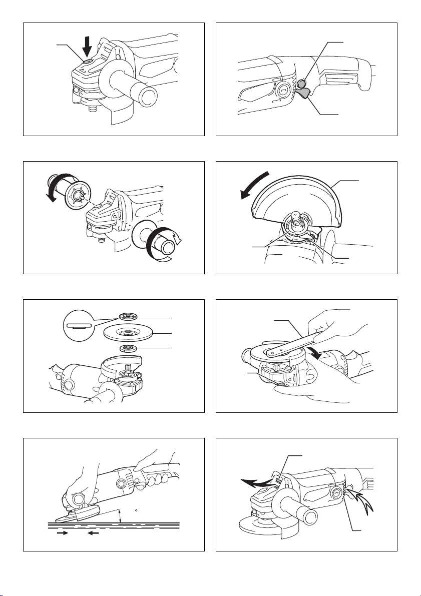
13. Limit mark
14. Brush holder cap
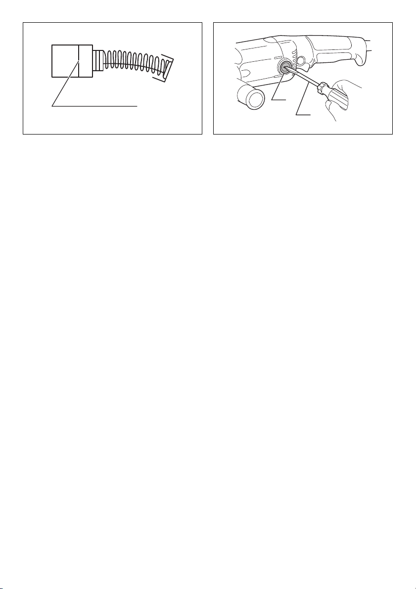
15. Screwdriver
SPECIFICATIONS
Model M9002 M9003
Depressed center wheel diameter 125 mm 150 mm
Max. wheel thickness 6 mm
Spindle thread M14 or 5/8” (country specific)
Rated speed (n)/No load speed (n
Overall length 361 mm 361 mm
Net weight 2.8 kg 2.8 kg
Safety class /II
• Due to our continuing program of research and development, the specifications herein are subject to change without
notice.
• Specifications may differ from country to country.
• Weight according to EPTA-Procedure 01/2003
Intended use
The tool is intended for grinding of metal and stone
materials without the use of water.
Power supply
The tool should be connected only to a power supply of
the same voltage as indicated on the nameplate, and can
only be operated on single-phase AC supply. They are
double-insulated and can, therefore, also be used from
sockets without earth wire.
For public low-voltage distribution systems of
between 220 V and 250 V.
Switching operations of electric apparatus cause voltage
fluctuations. The operation of this device under
unfavorable mains conditions can have adverse effects to
the operation of other equipment. With a mains
impedance equal or less than 0.44 Ohms it can be
presumed that there will be no negative effects. The
mains socket used for this device must be protected with
a fuse or protective circuit breaker having slow tripping
characteristics.
) 11,000 min
0
ENE077-2
ENF002-2
ENF100-1
General Power Tool Safety
Warnings GEA010-1
WARNING Read all safety warnings and all
instructions. Failure to follow the warnings and
instructions may result in electric shock, fire and/or
serious injury.
Save all warnings and
instructions for future reference.
-1
10,000 min
-1
GRINDER SAFETY WARNINGS
GEB110-3
Safety Warnings Common for Grinding Operations:
1. This power tool is intended to function as a
grinder. Read all safety warnings, instructions,
illustrations and specifications provided with this
power tool. Failure to follow all instructions listed
below may result in electric shock, fire and/or serious
injury.
2. Operations such as sanding, wire brushing,
polishing or cutting-off are not recommended to
be performed with this power tool. Operations for
which the power tool was not designed may create a
hazard and cause personal injury.
3. Do not use accessories which are not specifically
designed and recommended by the tool
manufacturer. Just because the accessory can be
attached to your power tool, it does not assure safe
operation.
4. The rated speed of the accessory must be at least
equal to the maximum speed marked on the power
tool. Accessories running faster than their rated
speed can break and fly apart.
5. The outside diameter and the thickness of your
accessory must be within the capacity rating of
your power tool. Incorrectly sized accessories
cannot be adequately guarded or controlled.
6. Threaded mounting of accessories must match
the grinder spindle thread. For accessories
mounted by flanges, the arbour hole of the
accessory must fit the locating diameter of the
flange. Accessories that do not match the mounting
hardware of the power tool will run out of balance,
vibrate excessively and may cause loss of control.
4
Page 5

7. Do not use a damaged accessory. Before each use
inspect the accessory such as abrasive wheels for
chips and cracks, backing pad for cracks, tear or
excess wear. If power tool or accessory is
dropped, inspect for damage or install an
undamaged accessory. After inspecting and
installing an accessory, position yourself and
bystanders away from the plane of the rotating
accessory and run the power tool at maximum noload speed for one minute. Damaged accessories
will normally break apart during this test time.
8. Wear personal protective equipment. Depending
on application, use face shield, safety goggles or
safety glasses. As appropriate, wear dust mask,
hearing protectors, gloves and workshop apron
capable of stopping small abrasive or workpiece
fragments. The eye protection must be capable of
stopping flying debris generated by various
operations. The dust mask or respirator must be
capable of filtrating particles generated by your
operation. Prolonged exposure to high intensity noise
may cause hearing loss.
9. Keep bystanders a safe distance away from work
area. Anyone entering the work area must wear
personal protective equipment. Fragments of
workpiece or of a broken accessory may fly away and
cause injury beyond immediate area of operation.
10. Hold the power tool by insulated gripping surfaces
only, when performing an operation where the
cutting accessory may contact hidden wiring or its
own cord. Cutting accessory contacting a “live” wire
may make exposed metal parts of the power tool “live”
and could give the operator an electric shock.
11. Position the cord clear of the spinning accessory.
If you lose control, the cord may be cut or snagged
and your hand or arm may be pulled into the spinning
accessory.
12. Never lay the power tool down until the accessory
has come to a complete stop. The spinning
accessory may grab the surface and pull the power
tool out of your control.
13. Do not run the power tool while carrying it at your
side. Accidental contact with the spinning accessory
could snag your clothing, pulling the accessory into
your body.
14. Regularly clean the power tool’s air vents. The
motor’s fan will draw the dust inside the housing and
excessive accumulation of powdered metal may
cause electrical hazards.
15. Do not operate the power tool near flammable
materials. Sparks could ignite these materials.
16. Do not use accessories that require liquid
coolants. Using water or other liquid coolants may
result in electrocution or shock.
Kickback and Related Warnings
Kickback is a sudden reaction to a pinched or snagged
rotating wheel, backing pad, brush or any other
accessory. Pinching or snagging causes rapid stalling of
the rotating accessory which in turn causes the
uncontrolled power tool to be forced in the direction
opposite of the accessory’s rotation at the point of the
binding.
For example, if an abrasive wheel is snagged or pinched
by the workpiece, the edge of the wheel that is entering
into the pinch point can dig into the surface of the material
causing the wheel to climb out or kick out. The wheel may
either jump toward or away from the operator, depending
on direction of the wheel’s movement at the point of
pinching. Abrasive wheels may also break under these
conditions.
Kickback is the result of power tool misuse and/or
incorrect operating procedures or conditions and can be
avoided by taking proper precautions as given below.
a) Maintain a firm grip on the power tool and
position your body and arm to allow you to resist
kickback forces. Always use auxiliary handle, if
provided, for maximum control over kickback or
torque reaction during start-up. The operator can
control torque reactions or kickback forces, if proper
precautions are taken.
b) Never place your hand near the rotating
accessory. Accessory may kickback over your hand.
c) Do not position your body in the area where
power tool will move if kickback occurs. Kickback
will propel the tool in direction opposite to the wheel’s
movement at the point of snagging.
d) Use special care when working corners, sharp
edges etc. Avoid bouncing and snagging the
accessory. Corners, sharp edges or bouncing have
a tendency to snag the rotating accessory and cause
loss of control or kickback.
e) Do not attach a saw chain woodcarving blade
or toothed saw blade. Such blades create frequent
kickback and loss of control.
Safety Warnings Specific for Grinding Operation:
a) Use only wheel types that are recommended
for your power tool and the specific guard
designed for the selected wheel. Wheels for which
the power tool was not designed cannot be
adequately guarded and are unsafe.
b) The grinding surface of centre depressed
wheels must be mounted below the plane of the
guard lip. An improperly mounted wheel that projects
through the plane of the guard lip cannot be
adequately protected.
c) The guard must be securely attached to the
power tool and positioned for maximum safety,
so the least amount of wheel is exposed towards
the operator. The guard helps to protect the operator
from broken wheel fragments, accidental contact with
wheel and sparks that could ignite clothing.
d) Wheels must be used only for recommended
applications. For example: do not grind with the
side of cut-off wheel. Abrasive cut-off wheels are
intended for peripheral grinding, side forces applied
to these wheels may cause them to shatter.
e) Always use undamaged wheel flanges that are
of correct size and shape for your selected wheel.
Proper wheel flanges support the wheel thus
reducing the possibility of wheel breakage. Flanges
for cut-off wheels may be different from grinding
wheel flanges.
f) Do not use worn down wheels from larger
power tools. Wheel intended for larger power tool is
not suitable for the higher speed of a smaller tool and
may burst.
5
Page 6

Additional Safety Warnings:
17. When using depressed centre grinding wheels, be
sure to use only fiberglass-reinforced wheels.
18. NEVER USE Stone Cup type wheels with this
grinder. This grinder is not designed for these types of
wheels and the use of such a product may result in
serious personal injury.
19. Be careful not to damage the spindle, the flange
(especially the installing surface) or the lock nut.
Damage to these parts could result in wheel
breakage.
20. Make sure the wheel is not contacting the
workpiece before the switch is turned on.
21. Before using the tool on an actual workpiece, let it
run for a while. Watch for vibration or wobbling
that could indicate poor installation or a poorly
balanced wheel.
22. Use the specified surface of the wheel to perform
the grinding.
23. Do not leave the tool running. Operate the tool
only when hand-held.
24. Do not touch the workpiece immediately after
operation; it may be extremely hot and could burn
your skin.
25. Observe the instructions of the manufacturer for
correct mounting and use of wheels. Handle and
store wheels with care.
26. Do not use separate reducing bushings or
adaptors to adapt large hole abrasive wheels.
27. Use only flanges specified for this tool.
28. For tools intended to be fitted with threaded hole
wheel, ensure that the thread in the wheel is long
enough to accept the spindle length.
29. Check that the workpiece is properly supported.
30. Pay attention that the wheel continues to rotate
after the tool is switched off.
31. If working place is extremely hot and humid, or
badly polluted by conductive dust, use a shortcircuit breaker (30 mA) to assure operator safety.
32. Do not use the tool on any materials containing
asbestos.
33. Do not use cloth work gloves during operation.
Fibers from cloth gloves may enter the tool, which
causes tool breakage.
SAVE THESE INSTRUCTIONS.
WARNING:
DO NOT let comfort or familiarity with product (gained
from repeated use) replace strict adherence to safety
rules for the subject product. MISUSE or failure to
follow the safety rules stated in this instruction
manual may cause serious personal injury.
FUNCTIONAL DESCRIPTION
CAUTION:
• Always be sure that the tool is switched off and
unplugged before adjusting or checking function on the
tool.
Shaft lock
CAUTION:
• Never actuate the shaft lock when the spindle is
moving. The tool may be damaged.
Press the shaft lock to prevent spindle rotation when
installing or removing accessories. (Fig. 1)
Switch action
CAUTION:
• Before plugging in the tool, always check to see that
the switch trigger actuates properly and returns to the
“OFF” position when released. (Fig. 2)
For tool without lock button
To start the tool, simply pull the switch trigger. Release
the switch trigger to stop.
For tool with lock button
CAUTION:
• Switch can be locked in “ON” position for ease of
operator comfort during extended use. Apply caution
when locking tool in “ON” position and maintain firm
grasp on tool.
To start the tool, simply pull the switch trigger. Release
the switch trigger to stop.
For continuous operation, pull the switch trigger and then
push in the lock button.
To stop the tool from the locked position, pull the switch
trigger fully, and then release it.
ASSEMBLY
CAUTION:
• Always be sure that the tool is switched off and
unplugged before carrying out any work on the tool.
Installing side grip (handle)
CAUTION:
• Always be sure that the side grip is installed securely
before operation.
Screw the side grip securely on the position of the tool as
shown in the figure. (Fig. 3)
Installing or removing wheel guard (For
depressed center wheel/Multi disc)
CAUTION:
• When using a depressed center grinding wheel/Multidisc, the wheel guard must be fitted on the tool so that
the closed side of the guard always points toward the
operator.
Mount the wheel guard with the protrusion on the wheel
guard band aligned with the notch on the bearing box.
Then rotate the wheel guard to such an angle that it can
protect the operator according to work. Be sure to tighten
the screw securely. (Fig. 4)
To remove wheel guard, follow the installation procedure
in reverse.
6
Page 7

Installing or removing depressed center
grinding wheel/Multi-disc (optional
accessory)
WARNING:
• Always use supplied guard when depressed center
grinding wheel/Multi-disc is on tool. Wheel can shatter
during use and guard helps to reduce chances of
personal injury.
Mount the inner flange onto the spindle. Fit the wheel/disc
on the inner flange and screw the lock nut onto the
spindle. (Fig. 5)
To tighten the lock nut, press the shaft lock firmly so that
the spindle cannot revolve, then use the lock nut wrench
and securely tighten clockwise. (Fig. 6)
To remove the wheel, follow the installation procedure in
reverse.
OPERATION
WARNING:
• It should never be necessary to force the tool. The
weight of the tool applies adequate pressure. Forcing
and excessive pressure could cause dangerous wheel
breakage.
• ALWAYS replace wheel if tool is dropped while
grinding.
• NEVER bang or hit grinding disc or wheel onto work.
• Avoid bouncing and snagging the wheel, especially
when working corners, sharp edges etc. This can
cause loss of control and kickback.
• NEVER use tool with wood cutting blades and other
sawblades. Such blades when used on a grinder
frequently kick and cause loss of control leading to
personal injury.
CAUTION:
• Never switch on the tool when it is in contact with the
workpiece, it may cause an injury to operator.
• Always wear safety goggles or a face shield during
operation.
• After operation, always switch off the tool and wait until
the wheel has come to a complete stop before putting
the tool down.
Grinding operation (Fig. 7)
ALWAYS hold the tool firmly with one hand on rear handle
and the other on the side handle. Turn the tool on and
then apply the wheel or disc to the workpiece.
In general, keep the edge of the wheel or disc at an angle
of about 15 degrees to the workpiece surface.
During the break-in period with a new wheel, do not work
the grinder in the B direction or it will cut into the
workpiece. Once the edge of the wheel has been rounded
off by use, the wheel may be worked in both A and B
direction.
MAINTENANCE
CAUTION:
• Always be sure that the tool is switched off and
unplugged before attempting to perform inspection or
maintenance.
• Never use gasoline, benzine, thinner, alcohol or the
like. Discoloration, deformation or cracks may result.
The tool and its air vents have to be kept clean. Regularly
clean the tool’s air vents or whenever the vents start to
become obstructed. (Fig. 8)
Replacing carbon brushes (Fig. 9)
Remove and check the carbon brushes regularly. Replace
when they wear down to the limit mark. Keep the carbon
brushes clean and free to slip in the holders. Both carbon
brushes should be replaced at the same time. Use only
identical carbon brushes.
Use a screwdriver to remove the brush holder caps. Take
out the worn carbon brushes, insert the new ones and
secure the brush holder caps. (Fig. 10)
To maintain product SAFETY and RELIABILITY, repairs,
any other maintenance or adjustment should be
performed by Makita Authorized Service Centers, always
using Makita replacement parts.
Noise
The typical A-weighted noise level determined according
to EN60745:
Model M9002
Sound pressure level (L
Sound power level (L
Uncertainty (K): 3 dB (A)
Model M9003
Sound pressure level (L
Sound power level (L
Uncertainty (K): 3 dB (A)
Wear ear protection.
Vibration
The vibration total value (tri-axial vector sum) determined
according to EN60745:
Work mode: surface grinding
Vibration emission (a
Uncertainty (K): 1.5 m/s
• The declared vibration emission value has been
measured in accordance with the standard test method
and may be used for comparing one tool with another.
• The declared vibration emission value may also be
used in a preliminary assessment of exposure.
• The declared vibration emission value is used for main
applications of the power tool. However if the power
tool is used for other applications, the vibration
emission value may be different.
WARNING:
• The vibration emission during actual use of the power
tool can differ from the declared emission value
depending on the ways in which the tool is used.
• Be sure to identify safety measures to protect the
operator that are based on an estimation of exposure in
the actual conditions of use (taking account of all parts
of the operating cycle such as the times when the tool
is switched off and when it is running idle in addition to
the trigger time).
): 91 dB (A)
pA
): 102 dB (A)
WA
): 90 dB (A)
pA
): 101 dB (A)
WA
): 9.0 m/s
h,AG
2
2
ENG905-1
ENG900-1
ENG902-1
7
Page 8

For European countries only
ENH101-18
EC Declaration of Conformity
Makita declares that the following Machine(s):
Designation of Machine:
Angle Grinder
Model No./Type: M9002, M9003
Conforms to the following European Directives:
2006/42/EC
They are manufactured in accordance with the following
standard or standardized documents:
EN60745
The Technical file in accordance with 2006/42/EC is
available from:
Makita, Jan-Baptist Vinkstraat 2, 3070, Belgium
2. 1. 2015
Yasushi Fukaya
Director
Makita, Jan-Baptist Vinkstraat 2, 3070, Belgium
8
Page 9

FRANÇAIS (Instructions d’origine)
Descriptif
1. Blocage de l’arbre
2. Bouton de verrouillage
3. Gâchette
4. Carter de meule
5. Vis
6. Boîtier d’engrenage
7. Contre-écrou
8. Meule à moyeu déporté
/multidisque
9. Flasque intérieur
10. Clé à contre-écrou
11. Sortie d’air
12. Entrée d’air
13. Repère d’usure
14. Bouchon de porte-charbon
15. Tournevis
SPÉCIFICATIONS
Modèle M9002 M9003
Diamètre de la meule à moyeu déporté 125 mm 150 mm
Épaisseur maximale de la meule 6 mm
Filetage de l’axe M14 ou 5/8” (selon le pays)
Vitesse nominale (n)/Vitesse à vide (n
Longueur totale 361 mm 361 mm
Poids net 2,8 kg 2,8 kg
Niveau de sécurité /II
• Étant donné l’évolution constante de notre programme de recherche et de développement, les spécifications
contenues dans ce manuel sont sujettes à des modifications sans préavis.
• Les spécifications peuvent varier suivant les pays.
• Poids conforme à la procédure EPTA 01/2003
Utilisations
L’outil est conçu pour le meulage des métaux et pierres
sans utilisation d’eau.
Alimentation
L’outil ne doit être raccordé qu’à une alimentation de la
même tension que celle qui figure sur la plaque
signalétique, et il ne peut fonctionner que sur un courant
secteur monophasé. Réalisé avec une double isolation, il
peut de ce fait être alimenté sans mise à la terre.
Pour les systèmes d’alimentation électrique publics à
basse tension compris entre 220 et 250 V.
La mise sous/hors tension des appareils électriques
entraîne des fluctuations de la tension. L’utilisation de cet
appareil sur une source d’alimentation inadéquate peut
affecter le fonctionnement d’autres appareils. On peut
considérer qu’il n’y aura pas d’effets négatifs si
l’impédance de la source d’alimentation est inférieure ou
égale à 0,44 Ohms. La prise de courant utilisée pour cet
appareil doit être protégée par un fusible ou un
disjoncteur de protection à déclenchement lent.
)11000 min
0
ENE077-2
ENF002-2
ENF100-1
Consignes de sécurité générales
des outils électriques GEA010-1
AVERTISSEMENT Veuillez lire toutes les
consignes de sécurité et les instructions. Il y a un
risque de choc électrique, d’incendie et/ou de blessure
grave si les consignes et les instructions ne sont pas
toutes respectées.
Conservez toutes les consignes
et instructions pour référence
ultérieure.
-1
10 000 min
-1
AVERTISSEMENTS DE SÉCURITÉ
RELATIFS À LA MEULEUSE
Consignes de sécurité courantes pour les opérations
de meulage :
1. Cet outil électrique est conçu pour fonctionner
comme une meuleuse. Lisez tous les
avertissements concernant la sécurité, les
instructions, les illustrations et les
caractéristiques fournis avec cet outil électrique. Il
y a risque d’électrocution, d’incendie et/ou de
blessures graves si les instructions énumérées cidessous ne sont pas respectées.
2. Les opérations comme le ponçage, le brossage à
brosse métallique, le polissage ou le tronçonnage
sont déconseillées avec cet outil électrique. Les
opérations pour lesquelles l’outil électrique n’a pas été
conçu peuvent générer un danger et occasionner des
blessures.
3. N’utilisez pas d’accessoires qui ne sont pas
spécifiquement conçus et recommandés par le
fabricant de l’outil. Le simple fait que l’accessoire
puisse être fixé à votre outil électrique ne signifie pas
que le fonctionnement sera sécurisé.
4. La vitesse nominale de l’accessoire doit être au
moins égale à la vitesse maximale indiquée sur
l’outil électrique. Les accessoires fonctionnant plus
rapidement que leur vitesse nominale risquent de se
casser et de voler en éclats.
5. Le diamètre externe et l’épaisseur de votre
accessoire doivent correspondre à la puissance
nominale de votre outil électrique. Des accessoires
aux dimensions inappropriées ne peuvent pas être
protégés ou contrôlés correctement.
6. Le montage fileté d’accessoires doit correspondre
au filetage de la broche de la meuleuse. Pour les
GEB110-3
9
Page 10

accessoires montés à l’aide de flasques, l’orifice
de l’accessoire doit correspondre au diamètre du
flasque. Les accessoires qui ne correspondent pas
au matériel de montage de l’outil électrique seront
déséquilibrés et subiront des vibrations excessives,
susceptibles d’occasionner une perte de contrôle.
7. N’utilisez pas d’accessoire endommagé. Avant
chaque utilisation, vérifiez que les accessoires,
tels que les meules, ne sont pas écaillés et
craquelés, que les patins de renfort ne sont pas
fissurés, déchirés ou excessivement usés. En cas
de chute de l’outil électrique ou d’un accessoire,
assurez-vous qu’il n’est pas endommagé et
remplacez-le au besoin par un accessoire en bon
état. Après avoir inspecté et installé un
accessoire, positionnez-vous ainsi que les
spectateurs à distance de l’accessoire en rotation
et faites fonctionner l’outil électrique à la vitesse
maximale à vide pendant une minute.
Normalement, tout accessoire endommagé se brisera
au cours de ce temps d’essai.
8. Portez un équipement de protection corporelle. En
fonction du type de travail à effectuer, utilisez un
écran facial, des lunettes étanches ou des lunettes
de protection. Au besoin, portez un masque antipoussières, des protège-tympans, des gants et un
tablier d’atelier capable d’arrêter les petits
fragments abrasifs ou des morceaux de la pièce à
travailler. La protection pour les yeux doit pouvoir
stopper les projections de débris générées par
diverses opérations. Le masque anti-poussières ou le
masque filtrant doit pouvoir filtrer les particules
générées lors des travaux. L’exposition prolongée à
un bruit d’intensité élevée peut entraîner la surdité.
9. Gardez les spectateurs à une distance de sécurité
de la zone de travail. Quiconque pénètre dans la
zone de travail doit porter un équipement de
protection corporelle. Des fragments de la pièce à
travailler ou d’un accessoire cassé peuvent être
projetés hors de la zone de travail immédiate et
entraîner des blessures.
10. Ne tenez l’outil électrique que par ses surfaces de
poigne isolées lorsque vous effectuez une
opération au cours de laquelle l’accessoire de
coupe peut entrer en contact avec des fils
dissimulés ou avec le cordon de l’outil. Il est
possible que le contact de l’accessoire tranchant avec
un fil sous tension mette les parties métalliques
exposées de l’outil sous tension, risquant ainsi de
provoquer un choc électrique chez l’utilisateur.
11. Éloignez le cordon de l’accessoire rotatif. En cas
de perte de contrôle, le cordon risque d’être coupé ou
accroché et votre main ou votre bras happé(e) par
l’accessoire rotatif.
12. Ne posez jamais l’outil électrique à terre tant que
l’accessoire ne s’est pas complètement arrêté.
L’accessoire rotatif peut accrocher la surface et vous
risquez de perdre le contrôle de l’outil électrique.
13. Ne faites pas tourner l’outil électrique si vous le
transportez à côté de vous. Un contact accidentel
avec l’accessoire rotatif pourrait accrocher vos
vêtements et attirer l’accessoire vers votre corps.
14. Nettoyez régulièrement les aérations de l’outil
électrique. Le ventilateur du moteur tire la poussière
à l’intérieur du boîtier et une accumulation excessive
de poudre métallique peut entraîner des chocs
électriques.
15. Ne faites pas fonctionner l’outil électrique à
proximité de matériaux inflammables. Les
étincelles risquent d’enflammer ces matériaux.
16. N’utilisez pas d’accessoires qui nécessitent des
liquides de refroidissement. L’utilisation d’eau ou de
liquides de refroidissement peut entraîner une
électrocution ou un choc électrique.
Rebond et avertissements afférents
Le rebond est une réaction soudaine suite à un pincement
ou accrochage d’une meule en rotation, d’un patin de
renfort, d’une brosse ou d’un autre accessoire. Un
pincement ou un accrochage peut entraîner le calage
rapide de l’accessoire rotatif, ce qui peut alors forcer l’outil
électrique hors de contrôle à tourner dans la direction
opposée au sens de rotation de l’accessoire, jusqu’à ce
qu'il se bloque.
Par exemple, si une meule est accrochée ou pincée par la
pièce à travailler, le rebord de la meule qui pénètre dans
le point de pincement risque de creuser dans la surface
du matériau, ce qui peut faire sortir la meule. La meule
risque de sauter dans votre direction ou dans la direction
opposée, en fonction du sens de rotation de la meule au
niveau du point de pincement. Les meules peuvent
également se casser dans ces conditions.
Le rebond est dû à une mauvaise utilisation de l’outil et/ou
à des procédures ou conditions de travail inappropriées. Il
peut être évité en prenant les mesures appropriées, telles
que celles indiquées ci-dessous.
a) Maintenez une prise ferme sur l’outil électrique
et positionnez votre corps et vos bras de façon à
pouvoir résister aux forces du rebond. Utilisez
toujours une poignée auxiliaire, le cas échéant,
pour contrôler au maximum les rebonds ou la
réaction du couple au démarrage. Vous pouvez
contrôler les réactions du couple ou les forces du
rebond si vous prenez les précautions nécessaires.
b) Ne placez jamais la main à proximité de
l’accessoire rotatif. L’accessoire risque de rebondir
sur votre main.
c) Ne positionnez pas votre corps dans la zone où
l’outil électrique se déplacera en cas de rebond.
Le rebond va propulser l’outil dans la direction
opposée au mouvement de la meule, au point
d’accrochage.
d) Soyez particulièrement prudent lorsque vous
travaillez dans des recoins, sur des rebords
tranchants, etc. Évitez de faire rebondir ou
d’accrocher l’accessoire. Les recoins, les rebords
tranchants ou les rebonds ont tendance à accrocher
l’accessoire rotatif et à provoquer une perte de
contrôle ou un rebond.
e) Ne fixez pas une lame de sculpteur à chaîne
coupante ou une lame de scie dentée. De telles
lames peuvent créer de fréquents rebonds et pertes
de contrôle.
Consignes de sécurité spécifiques pour l’opération
de meulage :
a) N’utilisez que les types de meules qui sont
recommandées pour votre outil électrique et le
carter spécifique conçu pour la meule
10
Page 11

sélectionnée. Les meules pour lesquelles l’outil
électrique n’a pas été conçu ne peuvent pas être
protégées de manière adéquate et ne sont pas sûres.
b) La surface de meulage des meules à moyeu
déporté doit être installée sous le plateau de la
lèvre du carter. Une meule mal montée qui est
projetée à travers le plateau de la lèvre du carter ne
peut pas être correctement protégée.
c) Pour une sécurité maximale, le carter doit être
solidement fixé à l’outil électrique et positionné
pour une sécurité optimale, de manière à exposer
la meule au minimum dans votre direction. Le
carter contribue à vous protéger des fragments de
meule brisée, du contact accidentel avec la meule et
des étincelles susceptibles d’enflammer les
vêtements.
d) Les meules doivent être utilisées uniquement
pour les applications recommandées. Par
exemple : ne meulez pas avec la face latérale de
la meule à tronçonner. Les meules à tronçonner
sont conçues pour un meulage périphérique, les
forces latérales appliquées à ces meules peuvent les
briser.
e) Utilisez toujours des flasques de meule en bon
état dont la taille et la forme sont adaptées à la
meule que vous avez choisie. Des flasques de
meule appropriés soutiennent la meule, réduisant
ainsi le risque de cassure de celle-ci. Les flasques
pour les meules tronçonneuses peuvent être
différents des flasques de meule ordinaire.
f) N’utilisez pas de meules usées issues d’outils
électriques plus grands. Les meules conçues pour
de grands outils électriques ne conviennent pas en
cas de vitesse élevée d’un outil plus petit et elles
risquent d’exploser.
Autres avertissements de sécurité :
17. Lors de l’utilisation de meules à moyeu déporté,
assurez-vous d’utiliser exclusivement des meules
renforcées de fibre de verre.
18. N’UTILISEZ JAMAIS de meule pour couper la
pierre avec cette meuleuse. Cette meuleuse n’est
pas destinée à ce type de meule et l’utilisation de ce
genre de produit peut entraîner de graves blessures
corporelles.
19. Prenez garde de ne pas endommager l’axe, le
flasque (tout particulièrement la surface
d’installation) ou le contre-écrou. La meule risque
de casser si ces pièces sont endommagées.
20. Assurez-vous que la meule n’entre pas en contact
avec la pièce à travailler avant de mettre l’outil
sous tension.
21. Avant d’utiliser l’outil sur la pièce elle-même,
laissez-le tourner un instant. Soyez attentif à toute
vibration ou sautillement pouvant indiquer que la
meule n’est pas bien installée ou qu’elle est mal
équilibrée.
22. Utilisez la face spécifiée de la meule pour meuler.
23. N’abandonnez pas l’outil alors qu’il tourne. Ne
faites fonctionner l’outil qu’une fois que vous
l’avez bien en main.
24. Ne touchez jamais la pièce à travailler juste après
l’opération ; elle peut être extrêmement chaude et
vous risquez de vous brûler.
25. Pour installer et utiliser correctement la meule,
veuillez suivre les instructions du fabricant.
Manipulez les meules avec soin et rangez-les en
lieu sûr.
26. N’utilisez aucun raccord de réduction ou
adaptateur séparé pour adapter un trou de meule
trop grand.
27. Utilisez exclusivement les flasques spécifiés pour
cet outil.
28. Dans le cas des outils conçus pour l’utilisation
avec une meule à trou fileté, assurez-vous que la
longueur du filetage de la meule convient à la
longueur de l’axe.
29. Assurez-vous que la pièce à travailler est
correctement soutenue.
30. Gardez à l’esprit que la meule continue de tourner
même une fois le contact coupé sur l’outil.
31. Si le site de travail est extrêmement chaud et
humide ou s’il y a beaucoup de poussières
conductrices dans l’air, utilisez un coupe-circuit
(30 mA) pour assurer votre sécurité.
32. N’utilisez l’outil sur aucun matériau contenant de
l’amiante.
33. N’utilisez pas de gants de travail en tissu pendant
l’utilisation. Les fibres des gants en tissu pourraient
pénétrer dans l’outil et l’endommager.
CONSERVEZ CES
INSTRUCTIONS.
AVERTISSEMENT :
NE vous laissez PAS tromper (au fil d’une utilisation
répétée) par un sentiment d’aisance et de familiarité
avec le produit, en négligeant le respect rigoureux
des consignes de sécurité qui accompagnent l’outil.
Une UTILISATION INCORRECTE de l’outil ou le nonrespect des consignes de sécurité indiquées dans ce
manuel d’instructions peuvent causer de graves
blessures corporelles.
DESCRIPTION DU
FONCTIONNEMENT
ATTENTION :
• Assurez-vous toujours que l’outil est éteint et
débranché avant de le régler ou vérifier son
fonctionnement.
Blocage de l’arbre
ATTENTION :
• N’activez jamais le blocage de l’arbre alors que l’axe
bouge. Vous pourriez endommager l’outil.
Appuyez sur le blocage de l’arbre pour empêcher l’axe de
tourner lors de l’installation ou du retrait des accessoires.
(Fig. 1)
Interrupteurs
ATTENTION :
• Avant de brancher l’outil, vérifiez toujours que la
gâchette fonctionne correctement et revient en position
d’arrêt « OFF » lorsqu’elle est relâchée. (Fig. 2)
11
Page 12

Pour les outils sans bouton de verrouillage
Pour mettre l’outil en marche, appuyez simplement sur la
gâchette. Pour l’arrêter, relâchez la gâchette.
Pour les outils avec bouton de verrouillage
ATTENTION :
• Pour votre confort, vous pouvez verrouiller le
commutateur en position de MARCHE en cas d’usage
prolongé. Soyez vigilant lorsque vous verrouillez l’outil
en position de MARCHE et gardez-le bien en main.
Pour mettre l’outil en marche, appuyez simplement sur la
gâchette. Pour l’arrêter, relâchez la gâchette.
Pour un fonctionnement continu, appuyez sur la gâchette
puis enfoncez le bouton de verrouillage.
Pour arrêter l’outil alors qu’il est en position verrouillée,
appuyez à fond sur la gâchette puis relâchez-la.
MONTAGE
ATTENTION :
• Avant d’effectuer toute intervention sur l’outil, assurezvous toujours qu’il est hors tension et débranché.
Installation de la poignée latérale
(manche)
ATTENTION :
• Avant d’utiliser l’outil, assurez-vous toujours que la
poignée latérale est installée de façon sûre.
Vissez la poignée latérale à fond sur la position prévue à
cet effet sur l’outil, comme illustré sur la figure. (Fig. 3)
Installation ou retrait du carter de meule
(pour les meules à moyeu déporté/
multidisques)
ATTENTION :
• Lors de l’utilisation d’une meule à moyeu déporté/d’un
multidisque, vous devez ajuster le carter de meule sur
l’outil, de sorte que la partie fermée du carter soit
toujours orientée vers vous.
Montez le carter de meule en alignant la partie saillante
de la bande du carter sur l’entaille du boîtier d’engrenage.
Faites ensuite pivoter le carter de meule selon un angle
qui permette de vous protéger selon le travail à exécuter.
Assurez-vous d’avoir serré la vis à fond. (Fig. 4)
Pour retirer le carter de meule, suivez la procédure
d’installation en sens inverse.
Installation ou retrait de la meule à moyeu
déporté/du multidisque (accessoire fourni
en option)
AVERTISSEMENT :
• Utilisez toujours le carter de meule fourni lorsque la
meule à moyeu déporté/le multidisque est installé(e)
sur l’outil. Comme la meule peut se rompre pendant
l’utilisation, le carter de meule réduit les risques de
blessure corporelle.
Montez le flasque intérieur sur l’axe. Ajustez la meule/le
disque sur le flasque intérieur et vissez le contre-écrou
sur l’axe. (Fig. 5)
Pour serrer le contre-écrou, appuyez fermement sur le
blocage de l’arbre pour empêcher l’axe de tourner, puis
12
utilisez la clé à contre-écrou pour serrer fermement dans
le sens des aiguilles d’une montre. (Fig. 6)
Pour retirer la meule, suivez la procédure d’installation en
sens inverse.
FONCTIONNEMENT
AVERTISSEMENT :
• Il ne doit jamais être nécessaire de forcer l’outil. Le
poids de l’outil lui-même suffit à assurer une pression
adéquate. Si vous forcez l’outil ou appliquez une
pression excessive sur celui-ci, vous risquez de casser
la meule, ce qui est dangereux.
• Remplacez TOUJOURS la meule si vous laissez
tomber l’outil pendant le meulage.
• Ne frappez JAMAIS le disque de meulage ou la meule
contre la pièce à travailler.
• Évitez de laisser la meule sautiller ou accrocher, tout
spécialement lorsque vous travaillez dans les coins,
sur les bords tranchants, etc. Cela peut causer une
perte de contrôle et un choc en retour.
• N’utilisez JAMAIS cet outil avec des lames à bois et
autres lames de scie. Les lames de ce type sautent
fréquemment lorsqu’elles sont utilisées sur une
meuleuse et risquent d’entraîner une perte de contrôle
pouvant causer des blessures corporelles.
ATTENTION :
• Pour éviter de vous blesser, ne mettez jamais l’outil en
marche alors qu’il se trouve en contact avec la pièce à
travailler.
• Pendant l’utilisation, portez toujours des lunettes de
sécurité ou un masque de protection.
• Après l’utilisation, mettez toujours l’outil hors tension et
attendez l’arrêt complet de la meule avant de reposer
l’outil.
Opération de meulage (Fig. 7)
Tenez TOUJOURS l’outil fermement en posant une main
sur le manche arrière et l’autre main sur le manche
latéral. Mettez l’outil en marche puis posez la meule ou le
disque sur la pièce à travailler.
En général, vous devez maintenir le bord de la meule ou
du disque sur un angle d’environ 15 degrés par rapport à
la surface de la pièce à travailler.
Pendant la période de rodage d’une meule neuve, ne
faites pas avancer la meuleuse dans le sens B, sinon elle
risque de couper la pièce à travailler. Une fois le tranchant
de la meule émoussé par son utilisation, la meule peut
être utilisée dans les sens A et B.
ENTRETIEN
ATTENTION :
• Assurez-vous toujours que l’appareil est éteint et
débranché avant d’effectuer tout travail d’inspection ou
d’entretien.
• N’utilisez jamais d’essence, de benzine, de diluant,
d’alcool ou de produit similaire. Ces produits risquent
de provoquer des décolorations, des déformations ou
des fissures.
L’outil et ses orifices d’aération doivent être maintenus
propres. Nettoyez les orifices d’aération de l’outil
régulièrement ou chaque fois qu’ils commencent à se
boucher. (Fig. 8)
Page 13

Remplacement des charbons (Fig. 9)
Retirez et vérifiez les charbons régulièrement.
Remplacez-les lorsqu’ils atteignent le repère d’usure.
Maintenez les charbons propres et en état de glisser
aisément dans les porte-charbons. Les deux charbons
doivent être remplacés en même temps. Utilisez
uniquement des charbons identiques.
Retirez les bouchons de porte-charbon à l’aide d’un
tournevis. Enlevez les charbons usés, insérez-en de
nouveaux et revissez solidement les bouchons de portecharbon. (Fig. 10)
Pour garantir la SÉCURITÉ et la FIABILITÉ du produit, les
réparations ainsi que tout autre travail d’entretien ou de
réglage doivent être effectués dans un centre d’entretien
Makita agréé, exclusivement avec des pièces de
rechange Makita.
Bruit
Les niveaux de bruit pondéré A typiques ont été mesurés
selon la norme EN60745 :
Modèle M9002
Niveau de pression sonore (L
Niveau de puissance sonore (L
Incertitude (K) : 3 dB (A)
) : 91 dB (A)
pA
) : 102 dB (A)
WA
Modèle M9003
Niveau de pression sonore (L
Niveau de puissance sonore (L
Incertitude (K) : 3 dB (A)
) : 90 dB (A)
pA
) : 101 dB (A)
WA
Portez des protections auditives.
Vibrations
La valeur totale de vibration (somme du vecteur triaxial) a
été déterminée selon la norme EN60745 :
Mode de fonctionnement : meulage de surface
Émission de vibrations (a
Incertitude (K) : 1,5 m/s
h, AG
2
) : 9,0 m/s
• La valeur de l’émission des vibrations déclarée a été
mesurée conformément à la méthode de test standard
et peut être utilisée afin de comparer des outils entre
eux.
• La valeur de l’émission des vibrations déclarée peut
également être utilisée lors d’une évaluation
préliminaire de l’exposition.
• La valeur de l’émission des vibrations déclarée est
utilisée pour les principales applications de l’outil
électrique. Cependant, si l’outil est utilisé pour d’autres
applications, la valeur de l’émission des vibrations peut
être différente.
AVERTISSEMENT :
• Selon la manière dont l’outil est utilisé, il est possible
que l’émission des vibrations pendant l’utilisation réelle
de l’outil électrique diffère de la valeur de l’émission
déclarée.
• Veillez à identifier les mesures de sécurité destinées à
protéger l’opérateur et établies à partir de l’estimation
de l’exposition dans les conditions réelles d’utilisation
(en prenant en compte toutes les étapes du cycle de
fonctionnement, telles que les périodes de mise hors
tension de l’outil, les périodes de fonctionnement au
ralenti et les périodes de mise en route).
ENG905-1
ENG900-1
2
ENG902-1
Pour les pays d’Europe uniquement
ENH101-18
Déclaration de conformité CE
Makita déclare que la/les machine(s) suivante(s) :
Nom de la machine :
Meuleuse d’Angle
N° de modèle/Type : M9002, M9003
sont conformes aux directives européennes
suivantes :
2006/42/CE
sont produites conformément aux normes ou documents
de normalisation suivants :
EN60745
Le dossier technique conforme à la norme 2006/42/CE
est disponible auprès de :
Makita, Jan-Baptist Vinkstraat 2, 3070, Belgique
2. 1. 2015
Yasushi Fukaya
Directeur
Makita, Jan-Baptist Vinkstraat 2, 3070, Belgique
13
Page 14

DEUTSCH (Originalanweisungen)
Erklärung der Gesamtdarstellung
1. Spindelarretierung
2. Arretiertaste
3. Ein/Aus-Schalter
4. Schutzhaube
5. Schraube
6. Lagergehäuse
7. Sicherungsmutter
8. Gekröpfte Trennschleifscheibe/
Multischeibe
9. Innenflansch
10. Sicherungsmutterschlüssel
11. Lüftungsschlitz
12. Schlitz für Lufteintritt
13. Verschleißgrenze
14. Bürstenhalterkappe
15. Schraubendreher
TECHNISCHE DATEN
Modell M9002 M9003
Durchmesser der gekröpften Scheibe 125 mm 150 mm
Max. Scheibendicke 6 mm
Spindelgewinde M14 oder 5/8 Zoll (länderspezifisch)
Nenndrehzahl (n)/Leerlaufdrehzahl (n
Gesamtlänge 361 mm 361 mm
Nettogewicht 2,8 kg 2,8 kg
Schutzklasse /II
• Aufgrund unserer beständigen Forschungen und Weiterentwicklungen sind Änderungen an den hier angegebenen
Technischen Daten ohne Vorankündigung vorbehalten.
• Die Technischen Daten können in den einzelnen Ländern voneinander abweichen.
• Gewicht entsprechend EPTA-Verfahren 01/2003
Verwendungszweck
Das Werkzeug ist für das Schleifen von Metall und Stein
ohne Verwendung von Wasser vorgesehen.
Stromversorgung
Das Werkzeug darf nur an eine Stromversorgung mit
Einphasen-Wechselstrom mit der auf dem Typenschild
angegebenen Spannung angeschlossen werden. Das
Werkzeug verfügt über ein doppelt isoliertes Gehäuse
und kann daher auch an einer Stromversorgung ohne
Schutzkontakt betrieben werden.
Für öffentliche NiederspannungsVersorgungssysteme mit einer Spannung zwischen
220 V und 250 V.
Schaltvorgänge von Elektrogeräten verursachen
Spannungsschwankungen. Der Betrieb dieses Gerätes
unter ungünstigen Netzstrombedingungen kann sich
nachteilig auf den Betrieb anderer Geräte auswirken. Bei
einer Netzstromimpedanz von 0,44 Ohm oder weniger ist
anzunehmen, dass keine negativen Effekte auftreten. Die
für dieses Gerät verwendete Netzsteckdose muss durch
eine Sicherung oder einen Schutzschalter mit trägen
Auslöseeigenschaften geschützt sein.
) 11.000 min
0
ENE077-2
ENF002-2
ENF100-1
Allgemeine Sicherheitshinweise
für Elektrowerkzeuge
WARNUNG Lesen Sie alle Sicherheitshinweise
und Anweisungen sorgfältig durch. Wenn die Hinweise
und Anweisungen nicht beachtet werden, besteht die
Gefahr eines Stromschlags, Brands und/oder das Risiko
von ernsthaften Verletzungen.
GEA010-1
-1
10.000 min
-1
Bewahren Sie alle Hinweise und
Anweisungen zur späteren
Referenz gut auf.
SICHERHEITSHINWEISE FÜR
SCHLEIFER
Allgemeine Sicherheitshinweise für Schleifarbeiten:
1. Dieses Elektrowerkzeug ist für den Einsatz als
Schleifer vorgesehen. Lesen Sie alle
Sicherheitshinweise, Anweisungen, Abbildungen
und Spezifikationen durch, die mit diesem
Elektrowerkzeug geliefert wurden. Werden nicht
alle der unten aufgeführten Anweisungen befolgt,
besteht die Gefahr eines Stromschlags, Brands und/
oder die Gefahr schwerer Verletzungen.
2. Arbeiten wie Schmirgeln, Drahtbürsten, Polieren
oder Abschneiden sollten mit diesem
Elektrowerkzeug nicht ausgeführt werden. Bei
Arbeiten, für die das Elektrowerkzeug nicht
vorgesehen ist, kann es zu gefährlichen Situationen
und zu Verletzungen kommen.
3. Verwenden Sie nur Zubehör, das vom Hersteller
des Geräts entwickelt oder vom Hersteller
ausdrücklich empfohlen wurde. Nur weil Sie ein
bestimmtes Zubehör am Werkzeug befestigen
können, bedeutet dies nicht, dass die Verwendung
gefahrlos möglich ist.
4. Die Nenndrehzahl des Zubehörs muss mindestens
der auf dem Elektrowerkzeug angegebenen
Höchstdrehzahl entsprechen. Zubehör, das mit
einer höheren Drehzahl als der zulässigen Drehzahl
betrieben wird, kann zerbersten, wobei Teile mit hoher
Geschwindigkeit durch die Luft fliegen.
GEB110-3
14
Page 15

5. Außendurchmesser und Dicke von Zubehör
müssen innerhalb der Nennwerte des
Elektrowerkzeugs liegen. Zubehör in unzulässiger
Größe kann nicht angemessen abgedeckt oder
betrieben werden.
6. Bei Gewindemontage muss das Zubehörteil auf
das Gewinde der Schleifspindel passen. Bei
Flanschmontage muss die Bohrung des
Zubehörteils die richtige Größe für den Flansch
besitzen. Zubehörteile, die nicht den Montageteilen
des Elektrowerkzeugs entsprechen, laufen
exzentrisch, schwingen stark und führen zum
Kontrollverlust.
7. Verwenden Sie kein beschädigtes Zubehör.
Überprüfen Sie vor jeder Verwendung das
Zubehör, beispielsweise die Schleifscheiben auf
Splitter und Risse, die Stützscheibe auf Risse,
Abrisse oder übermäßigen Verschleiß. Wenn das
Elektrowerkzeug oder ein Zubehör zu Boden
gefallen sein sollte, überprüfen Sie Werkzeug bzw.
Zubehör auf Beschädigungen und tauschen Sie
ggf. beschädigte Teile gegen unbeschädigte Teile
aus. Nachdem Sie das Zubehör überprüft und
montiert haben, halten Sie und Umstehende
Abstand vom rotierenden Zubehörteil und lassen
Sie das Elektrowerkzeug eine Minute mit
maximaler Leerlaufdrehzahl laufen. Beschädigtes
Zubehör zerbirst bei diesem Test für gewöhnlich.
8. Tragen Sie eine persönliche Schutzausrüstung.
Tragen Sie je nach Arbeitsaufgabe einen
Gesichtsschutz oder eine Schutzbrille. Soweit
angemessen, tragen Sie Staubmaske,
Gehörschutz, Schutzhandschuhe oder
Spezialschürze, um kleine Schleif- und
Materialpartikel von Ihnen fernzuhalten. Der
Augenschutz muss umherfliegende Fremdkörper
abhalten können, die bei verschiedenen Arbeiten
auftreten können. Die Staub- oder Atemschutzmaske
muss Partikel herausfiltern können, die bei
verschiedenen Arbeiten entstehen. Lange und
intensive Lärmeinwirkung kann zu Gehörverlust
führen.
9. Achten Sie darauf, dass Umstehende den
Sicherheitsabstand zum Arbeitsbereich einhalten.
Jeder, der den Arbeitsbereich betritt, muss eine
Schutzausrüstung tragen. Splitter des Werkstücks
oder eines geborstenen Zubehörteils können
umherfliegen und auch außerhalb des eigentlichen
Arbeitsbereichs noch zu Verletzungen führen.
10. Halten Sie das Elektrowerkzeug an den isolierten
Griffflächen, wenn Sie unter Bedingungen
arbeiten, bei denen das Schneidwerkzeug nicht
sichtbare Stromkabel oder das eigene Kabel
berühren kann. Bei Kontakt des Werkzeugs mit
einem stromführenden Kabel wird der Strom an die
Metallteile des Elektrowerkzeugs und dadurch an den
Bediener weitergeleitet, und der Bediener erleidet
einen Stromschlag.
11. Halten Sie das Netzkabel von rotierendem
Zubehör fern. Falls Sie die Kontrolle über das
Elektrowerkzeug verlieren, kann das Netzkabel
durchtrennt oder erfasst werden, oder Ihre Hand oder
Ihr Arm kann in das rotierende Zubehör geraten.
12. Legen Sie das Elektrowerkzeug erst ab, nachdem
rotierendes Zubehör zum völligen Stillstand
gekommen ist. Das rotierende Zubehör könnte
Kontakt zur Auflagefläche erhalten, sodass Sie die
Kontrolle über das Elektrowerkzeug verlieren.
13. Schalten Sie das Elektrowerkzeug immer aus,
bevor Sie es transportieren. Ihre Kleidung kann
durch unbeabsichtigten Kontakt mit dem sich
drehenden Zubehör erfasst werden, und das Zubehör
kann sich in Ihren Körper bohren.
14. Reinigen Sie die Lüftungsschlitze des
Elektrowerkzeugs regelmäßig. Der Motorventilator
zieht Staub in das Gehäuse hinein, wobei eine
übermäßige Ansammlung von Metallspänen Gefahren
durch elektrischen Strom verursachen kann.
15. Betreiben Sie das Elektrowerkzeug nicht in der
Nähe brennbarer Materialien. Diese Materialien
können durch Funken entflammt werden.
16. Verwenden Sie keine Zubehörteile, die flüssige
Kühlmittel benötigen. Bei Verwendung von Wasser
oder anderen flüssigen Kühlmitteln können Sie einen
Stromschlag erleiden.
Rückschläge und entsprechende Warnhinweise
Ein Rückschlag ist eine plötzliche Reaktion einer
verklemmten oder verfangenen rotierenden
Schleifscheibe, Stützscheibe, der Bürste oder anderen
Zubehörs. Durch Verklemmen oder Verfangen kommt es
zu einem plötzlichen Stillstand des rotierenden Zubehörs,
sodass das Elektrowerkzeug am Punkt des Festfahrens in
die der Rotationsrichtung des Zubehörs
entgegengesetzte Richtung gezwungen wird.
Verklemmt sich beispielsweise eine Schleifscheibe im
Werkstück, kann die Kante, die in den Punkt des
Verklemmens eindringt, in die Oberfläche des Materials
eindringen, sodass die Scheibe ausschlägt. Die Scheibe
springt entweder in Richtung des Bedieners oder vom
Bediener weg; dies hängt von der Richtung der
Scheibenbewegung am Punkt der Blockade ab. Unter
diesen Umständen können Schleifscheiben auch
zerbersten.
Ein Rückschlag ist auf eine Zweckentfremdung bzw.
inkorrekte Betriebsweise oder auf einen fehlerhaften
Zustand des Elektrowerkzeugs zurückzuführen und kann
durch die im Folgenden aufgeführten
Vorsichtsmaßnahmen verhindert werden.
a) Halten Sie das Elektrowerkzeug stets mit
beiden Händen gut fest und halten Sie Ihren
Körper und Ihre Arme so, dass Sie Rückschläge
abfangen können. Verwenden Sie immer den
Zusatzgriff, sofern vorhanden, um größtmögliche
Kontrolle über Rückschlagkräfte oder
Reaktionsmomente beim Hochlauf zu haben. Bei
geeigneten Vorsichtsmaßnahmen können
Rückschlag- und Reaktionskräfte sicher vom
Bediener beherrscht werden.
b) Bringen Sie Ihre Hand niemals in die Nähe von
rotierendem Zubehör. Das Zubehör könnte
zurückschlagen und Ihre Hand treffen.
c) Meiden Sie mit Ihrem Körper den Bereich, in
den sich das Elektrowerkzeug bei einem
Rückschlag bewegen würde. Das Elektrowerkzeug
wird am Punkt der Blockade in die der
Rotationsrichtung der Scheibe entgegengesetzte
Richtung zurückgeschlagen.
15
Page 16

d) Arbeiten Sie im Bereich von Ecken, scharfen
Kanten usw. besonders vorsichtig. Verhindern
Sie, dass das Zubehör vom Werkstück
zurückprallt und verklemmt. Ecken, scharfe
Kanten und sonstige Hindernisse neigen zum
Verklemmen des rotierenden Zubehörs und können
zum Verlust der Kontrolle oder zu einem
Rückschlagen führen.
e) Verwenden Sie kein Ketten- oder gezähntes
Sägeblatt. Derartige Blätter verursachen häufig ein
Rückschlagen und führen zum Kontrollverlust.
Spezielle Sicherheitshinweise für den Schleifbetrieb:
a) Verwenden Sie ausschließlich die für dieses
Elektrowerkzeug zugelassenen Scheibentypen
und die für diese Schleifscheiben vorgesehene
Schutzhaube. Schleifscheibe, die nicht für das
Elektrowerkzeug vorgesehen sind, können nicht
ausreichend abgeschirmt werden und stellen
Gefahrenquellen dar.
b) Die Schleifoberfläche von gekröpften
Schleifscheiben muss unterhalb der Ebene der
Schutzhaube montiert werden. Eine unsachgemäß
montierte Scheibe, die über die Ebene der
Schutzhaube hinausragt, kann nicht ausreichend
geschützt werden.
c) Zur optimalen Sicherheit muss die
Schutzhaube sicher am Elektrowerkzeug
angebracht und positioniert sein, sodass der
kleinstmögliche Teil der Scheibe in Richtung
Bediener frei liegt. Die Schutzabdeckung soll den
Bediener vor Bruchstücken und zufälligem Kontakt
mit der Scheibe und Funken, welche die Kleidung
entzünden könnten, schützen.
d) Schleifscheiben dürfen ausschließlich für die
vorgesehenen Arbeiten verwendet werden.
Beispiel: Schleifen Sie nie mit der Seitenfläche
einer Trennscheibe. Trennscheiben sind zum
Materialabtrag mit der Kante der Scheibe bestimmt.
Bei seitlicher Krafteinwirkung auf diese Scheiben
können sie zerbrechen.
e) Verwenden Sie immer unbeschädigte
Spannflansche in der richtigen Größe und Form
für die von Ihnen gewählte Schleifscheibe. Die
richtigen Scheibenflansche unterstützen die
Schleifscheibe, sodass die Möglichkeit des
Scheibenbruchs vermindert wird. Flansche für
Trennscheiben unterscheiden sich möglicherweise
von Flanschen für Schleifscheiben.
f) Verwenden Sie keine abgenutzten
Schleifscheiben von größeren
Elektrowerkzeugen. Schleifscheiben für größere
Elektrowerkzeuge sind nicht für die höheren
Drehzahlen von kleineren Elektrowerkzeugen
ausgelegt und können bersten.
Zusätzliche Sicherheitshinweise:
17. Verwenden Sie nur glasfaserverstärkte
Schleifscheiben als gekröpfte
Trennschleifscheiben.
18. Verwenden Sie mit diesem Schleifer NIEMALS
Steinschleiftöpfe. Dieser Schleifer ist nicht für diese
Art von Scheiben ausgelegt und die Verwendung
dieser Scheiben kann zu schweren Verletzungen
führen.
16
19. Achten Sie sorgfältig darauf, dass Spindel,
Flansch (insbesondere die Ansatzfläche) und
Sicherungsmutter nicht beschädigt werden. Eine
Beschädigung dieser Teile kann zu einem
Scheibenbruch führen.
20. Stellen Sie vor dem Einschalten des Werkzeugs
sicher, dass die Scheibe das Werkstück nicht
berührt.
21. Bevor Sie das Werkzeug auf das zu bearbeitende
Werkstück ansetzen, lassen Sie es einige Zeit
ohne Last laufen. Achten Sie auf Vibrationen und
Schlagen; beide Anzeichen können auf eine
schlecht ausgewuchtete oder nicht fachgerecht
eingebaute Schleifscheibe hindeuten.
22. Verwenden Sie für Schleifarbeiten ausschließlich
die dafür vorgesehene Fläche der Schleifscheibe.
23. Lassen Sie das Werkzeug nicht unbeaufsichtigt
eingeschaltet. Das Werkzeug darf nur dann in
Betrieb sein, wenn es von Hand festgehalten wird.
24. Vermeiden Sie eine Berührung des Werkstücks
unmittelbar nach der Bearbeitung, da es dann
noch sehr heiß sein und somit
Hautverbrennungen verursachen kann.
25. Befolgen Sie die Anweisungen des Herstellers zur
korrekten Montage und Verwendung von
Schleifscheiben. Behandeln und lagern Sie
Schleifscheiben mit Sorgfalt.
26. Verwenden Sie keine separaten Reduzierbuchsen
oder Adapter zur Anpassung von Schleifscheiben
mit großem Durchmesser.
27. Verwenden Sie ausschließlich die für dieses
Werkzeug vorgeschriebenen Flansche.
28. Wenn eine Trennscheibe mit Gewindebohrung am
Werkzeug montiert werden soll, achten Sie darauf,
dass das Gewinde der Trennscheibe tief genug für
die Spindellänge ist.
29. Vergewissern Sie sich, dass das Werkstück sicher
eingespannt ist.
30. Beachten Sie, dass sich die Schleifscheibe nach
dem Ausschalten des Werkzeugs noch
weiterdreht.
31. Falls der Arbeitsplatz sehr heiß, feucht oder durch
leitfähigen Staub stark verschmutzt ist, verwenden
Sie zum Schutz des Bedieners einen
Kurzschlussschalter (30 mA).
32. Verwenden Sie dieses Werkzeug nicht zum
Bearbeiten von asbesthaltigen Materialien.
33. Tragen Sie bei der Arbeit mit diesem Werkzeug
keine Arbeitshandschuhe aus Stoff. Fasern der
Stoffhandschuhe könnten in das Werkzeug gelangen
und zum Ausfall des Werkzeugs führen.
BEWAHREN SIE DIESE
ANLEITUNG SORGFÄLTIG AUF.
WARNUNG:
Lassen Sie sich NIE durch Bequemlichkeit oder (aus
fortwährendem Gebrauch gewonnener) Vertrautheit
mit dem Werkzeug dazu verleiten, die
Sicherheitsregeln für das Werkzeug zu missachten.
Bei MISSBRÄUCHLICHER Verwendung des
Werkzeugs oder bei Missachtung der in diesem
Handbuch enthaltenen Sicherheitshinweise kann es
zu schweren Verletzungen kommen.
Page 17

FUNKTIONSBESCHREIBUNG
ACHTUNG:
• Schalten Sie das Werkzeug stets aus und ziehen Sie
den Stecker, bevor Sie Einstellungen oder eine
Funktionsprüfung am Werkzeug vornehmen.
Spindelarretierung
ACHTUNG:
• Betätigen Sie die Spindelarretierung niemals bei
rotierender Spindel. Andernfalls kann das Werkzeug
beschädigt werden.
Drücken Sie die Spindelarretierung, um die Spindel bei
der Montage oder Demontage von Zubehör zu blockieren.
(Abb. 1)
Einschalten
ACHTUNG:
• Achten Sie vor dem Einstecken des
Werkzeugnetzsteckers in die Steckdose darauf, dass
sich der Ein/Aus-Schalter korrekt bedienen lässt und
beim Loslassen in die Position „OFF“ (AUS)
zurückkehrt. (Abb. 2)
Für Werkzeuge ohne Arretiertaste
Betätigen Sie zum Starten des Werkzeugs einfach den
Ein/Aus-Schalter. Lassen Sie zum Ausschalten des
Werkzeugs den Ein/Aus-Schalter los.
Für Werkzeuge mit Arretiertaste
ACHTUNG:
• Um die Bedienung bei längerem Gebrauch zu
vereinfachen, kann der Schalter in der Stellung „ON“
(EIN) arretiert werden. Seien Sie vorsichtig, wenn der
Schalter des Werkzeugs in der Position „ON“ (EIN)
arretiert ist, und halten Sie das Werkzeug gut fest.
Betätigen Sie zum Starten des Werkzeugs einfach den
Ein/Aus-Schalter. Lassen Sie zum Ausschalten des
Werkzeugs den Ein/Aus-Schalter los.
Für einen Dauerbetrieb betätigen Sie den Ein/AusSchalter, und drücken Sie dann die Arretiertaste hinein.
Zur Aufhebung der Arretierung müssen Sie den Ein/AusSchalter bis zum Anschlag betätigen und anschließend
loslassen.
MONTAGE
ACHTUNG:
• Schalten Sie das Werkzeug stets aus und ziehen Sie
den Netzstecker, bevor Sie irgendwelche Arbeiten am
Werkzeug durchführen.
Einsetzen des Seitengriffs (Handgriff)
ACHTUNG:
• Vergewissern Sie sich vor dem Betrieb stets, dass der
Seitengriff ordnungsgemäß montiert ist.
Schrauben Sie den Seitengriff an der in der Abbildung
gezeigten Position am Werkzeug fest. (Abb. 3)
Montage und Demontage der
Schutzhaube (für gekröpfte Scheiben/
Multischeiben)
ACHTUNG:
• Bei Verwendung einer gekröpften Trennschleifscheibe/
Multischeibe muss die Schutzhaube so am Werkzeug
angebracht werden, dass die geschlossene Seite stets
in Richtung Bediener zeigt.
Montieren Sie die Schutzhaube so, dass der Vorsprung
am Schutzhaubenring an der Nut im Lagergehäuse
ausgerichtet ist. Drehen Sie anschließend die
Schutzhaube in einen solchen Winkel, in dem der
Bediener bei seiner Arbeit entsprechend geschützt wird.
Achten Sie darauf, die Schraube fest anzuziehen.
(Abb. 4)
Zum Demontieren der Schutzhaube befolgen Sie die
Vorgehensweise zum Einbauen in umgekehrter
Reihenfolge.
Montage und Demontage der gekröpften
Trennschleifscheibe/Multischeibe
(Sonderzubehör)
WARNUNG:
• Wenn die gekröpfte Trennschleifscheibe/Multischeibe
am Werkzeug befestigt ist, muss stets die mitgelieferte
Schutzhaube verwendet werden. Die Scheibe kann
während des Gebrauchs zerbersten. Durch die
Schutzhaube wird die Verletzungsgefahr deutlich
verringert.
Setzen Sie den Innenflansch auf die Spindel. Setzen Sie
die Trenn-/Schleifscheibe auf den Innenflansch und
schrauben Sie die Sicherungsmutter auf die Spindel.
(Abb. 5)
Drücken Sie zum Anziehen der Sicherungsmutter die
Spindelarretierung fest, um die Spindel zu blockieren;
ziehen Sie dann die Mutter mit dem
Sicherungsmutterschlüssel im Uhrzeigersinn fest an.
(Abb. 6)
Zum Entnehmen der Scheibe befolgen Sie die
Vorgehensweise zum Einbauen in umgekehrter
Reihenfolge.
BETRIEB
WARNUNG:
• Es sollte nicht notwendig sein, Druck auf das
Werkzeug auszuüben. Das Eigengewicht des
Werkzeugs übt ausreichenden Druck aus.
Gewaltanwendung und übermäßiger Druck können zu
einem gefährlichen Schleifscheibenbruch führen.
• Wechseln Sie die Schleifscheibe IMMER aus, falls das
Werkzeug während der Arbeit fallen gelassen wurde.
• Eine Schleif- oder Trennscheibe darf NIEMALS gegen
das Werkstück geschlagen oder gestoßen werden.
• Achten Sie besonders beim Bearbeiten von Ecken,
scharfen Kanten usw. darauf, dass die Schleifscheibe
nicht springt oder hängen bleibt. Dies könnte den
Verlust der Kontrolle und Rückschläge verursachen.
• Verwenden Sie das Werkzeug NIEMALS mit
Holzschneide- oder anderen Sägeblättern. Solche
Sägeblätter verursachen bei Verwendung an einem
17
Page 18

Schleifer häufiges Rückschlagen und Verlust der
Kontrolle, was zu Verletzungen führen kann.
ACHTUNG:
• Schalten Sie das Werkzeug niemals ein, wenn es in
Kontakt mit dem Werkstück steht, da dies eine
Verletzungsgefahr für den Bediener darstellt.
• Tragen Sie bei der Arbeit stets eine Schutzbrille oder
einen Gesichtsschutz.
• Schalten Sie das Werkzeug nach der Arbeit stets aus
und warten Sie, bis die Scheibe zum völligen Stillstand
gekommen ist, bevor Sie das Werkzeug ablegen.
Schleifbetrieb (Abb. 7)
Halten Sie das Werkzeug IMMER mit einer Hand am
hinteren Griff und mit der anderen am Seitengriff fest.
Schalten Sie das Werkzeug ein und bringen Sie die
Trenn- oder Schleifscheibe an das Werkstück.
Halten Sie die Trenn- oder Schleifscheibe im Allgemeinen
in einem Winkel von etwa 15 Grad zur
Werkstoffoberfläche.
Bewegen Sie den Schleifer beim Einschleifen einer neuen
Schleifscheibe nicht in Richtung B, weil die Schleifscheibe
sonst in das Werkstück einschneidet. Sobald die
Schleifscheibenkante durch Gebrauch abgerundet ist,
kann die Schleifscheibe sowohl in Richtung A als auch in
Richtung B bewegt werden.
WARTUNG
ACHTUNG:
• Schalten Sie das Gerät aus und ziehen Sie immer den
Netzstecker, bevor Sie Inspektionen oder
Wartungsarbeiten am Gerät vornehmen.
• Verwenden Sie zum Reinigen niemals Kraftstoffe,
Benzin, Verdünner, Alkohol oder ähnliches. Dies kann
zu Verfärbungen, Verformungen oder Rissen führen.
Halten Sie das Werkzeug und die Lüftungsschlitze des
Werkzeugs stets sauber. Reinigen Sie die
Lüftungsschlitze des Werkzeugs regelmäßig oder bei
Beginn einer Verstopfung. (Abb. 8)
Ersetzen der Kohlebürsten (Abb. 9)
Entnehmen und überprüfen Sie die Kohlebürsten in
regelmäßigen Abständen. Wenn die Kohlebürsten bis zur
Verschleißgrenze abgenutzt sind, müssen die
Kohlebürsten durch neue ersetzt werden. Halten Sie die
Kohlebürsten sauber und sorgen Sie dafür, dass die
Bürsten locker in den Halterungen gleiten. Ersetzen Sie
immer beide Kohlebürsten gleichzeitig. Verwenden Sie
nur identische Kohlebürsten.
Nehmen Sie die Bürstenhalterkappen mit Hilfe eines
Schraubendrehers ab. Entnehmen Sie die verbrauchten
Kohlebürsten, setzen Sie neue Bürsten ein und bringen
Sie die Bürstenhalterkappen wieder fest an. (Abb. 10)
Zur Gewährleistung von SICHERHEIT und
ZUVERLÄSSIGKEIT des Produkts sollten Reparaturen,
Wartungsarbeiten und Einstellungen nur durch von
Makita autorisierte Servicecenter durchgeführt und
ausschließlich Makita-Ersatzteile verwendet werden.
Schallpegel
ENG905-1
Typischer A-bewerteter Schallpegel nach EN60745:
Modell M9002
Schalldruckpegel (L
Schallleistungspegel (L
Abweichung (K): 3 dB (A)
): 91 dB (A)
pA
): 102 dB (A)
WA
Modell M9003
Schalldruckpegel (L
Schallleistungspegel (L
Abweichung (K): 3 dB (A)
): 90 dB (A)
pA
): 101 dB (A)
WA
Tragen Sie Gehörschutz.
Schwingung
ENG900-1
Schwingungsgesamtwerte (Vektorsumme dreier Achsen)
nach EN60745:
Arbeitsmodus: Planschleifen
Vibrationsemission (a
Abweichung (K): 1,5 m/s
h,AG
2
): 9,0 m/s
2
ENG902-1
• Der hier angegebene Wert für die erzeugten
Schwingungen wurde gemäß dem genormten
Testverfahren ermittelt und kann als Vergleich zu
anderen Werkzeugen herangezogen werden.
• Der angegebene Wert für die erzeugten Schwingungen
ist außerdem für eine vorbeugende Bewertung der
Belastung zu verwenden.
• Der angegebene Wert für die erzeugten Schwingungen
gilt, wenn das Elektrowerkzeug für den vorgesehenen
Zweck verwendet wird. Wenn das Werkzeug für andere
Zwecke verwendet wird, kann der Wert für die
Schwingungsbelastung jedoch von dem hier
aufgeführten Wert abweichen.
WARNUNG:
• Die Schwingungsbelastung kann bei tatsächlichem
Gebrauch des Elektrowerkzeugs in Abhängigkeit von
der Handhabung des Elektrowerkzeugs von dem hier
aufgeführten Wert abweichen.
• Stellen Sie sicher, dass Schutzmaßnahmen für den
Bediener getroffen werden, die auf den unter den
tatsächlichen Arbeitsbedingungen zu erwartenden
Belastungen beruhen (beziehen Sie alle Bestandteile
des Arbeitsablaufs ein, also zusätzlich zu den
Arbeitszeiten auch Zeiten, in denen das Werkzeug
ausgeschaltet ist oder ohne Last läuft).
Nur für europäische Länder
ENH101-18
EG-Konformitätserklärung
Makita erklärt, dass die nachfolgende(n) Maschine(n):
Bezeichnung der Maschine(n):
Winkelschleifer
Nummer/Typ des Modells: M9002, M9003
den folgenden Richtlinien der Europäischen Union
genügt/genügen:
2006/42/EG
18
Page 19

Sie werden gemäß den folgenden Standards oder
Normen gefertigt:
EN60745
Die technischen Unterlagen gemäß 2006/42/EG sind
erhältlich von:
Makita, Jan-Baptist Vinkstraat 2, 3070, Belgien
2. 1. 2015
Yasushi Fukaya
Makita, Jan-Baptist Vinkstraat 2, 3070, Belgien
Direktor
19
Page 20

Makita Jan-Baptist Vinkstraat 2, 3070, Belgium
Makita Corporation Anjo, Aichi, Japan
885412-993 www.makita.com
ALA
 Loading...