

Page 1
GB Hammer Drill Instruction Manual
M8100
M8101
F Perceuse à Percussion Manuel d’instructions
D Schlagbohrmaschine Betriebsanleitung
I Trapano a percussione Istruzioni per l’uso
NL Hamerboor Gebruiksaanwijzing
E Rotomartillo Manual de instrucciones
P Furadeira de Impacto Manual de instruções
DK Borehammer Brugsanvisning
GR Κρουστικό τρυπάνι Οδηγίες χρήσεως
TR Darbeli matkap Kullanma kılavuzu
Page 2
12
4
1
2
3
5
6
7
8
9
10
12
1
11
13
14
15
A
B
16
011089 011090
34
56
78
2
011095 011091
011092 011093
011094 015487
Page 3
ENGLISH (Original instructions)
Explanation of general view
1Grip base
2 Teeth
3 Side grip (auxiliary handle)
4Protrusion
5 Loosen
6Tighten
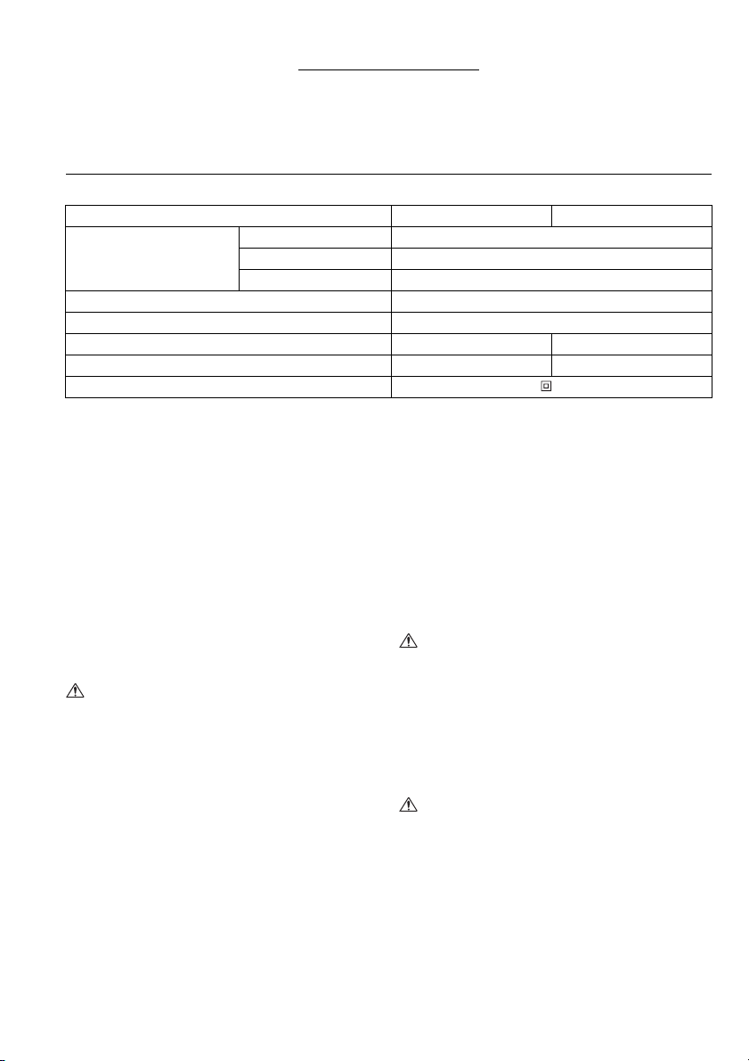
SPECIFICATIONS
Model M8100 M8101
Capacities
No load speed (min
Blows per minute 0 – 48,000
Overall length 296 mm 295 mm
Net weight 2.1 kg 2.0 kg
Safety class /II
• Due to our continuing program of research and
development, the specifications herein are subject to
change without notice.
• Specifications may differ from country to country.
• Weight according to EPTA-Procedure 01/2003
Intended use
The tool is intended for impact drilling in brick, concrete
and stone as well as for drilling without impact in wood,
metal, ceramic and plastic.
Power supply
The tool should be connected only to a power supply of
the same voltage as indicated on the nameplate, and can
only be operated on single-phase AC supply. They are
double-insulated and can, therefore, also be used from
sockets without earth wire.
General Power Tool Safety Warnings
WARNING Read all safety warnings and all
instructions. Failure to follow the warnings and
instructions may result in electric shock, fire and/or
serious injury.
Save all warnings and instructions for future
reference.
HAMMER DRILL SAFETY WARNINGS
1. Wear ear protectors when impact drilling.
Exposure to noise can cause hearing loss.
2. Use auxiliary handle(s), if supplied with the tool.
Loss of control can cause personal injury.
3. Hold power tool by insulated gripping surfaces,
when performing an operation where the cutting
accessory may contact hidden wiring or its own
cord. Cutting accessory contacting a “live” wire may
make exposed metal parts of the power tool “live”
and could give the operator an electric shock.
7 Drill chuck
8 Chuck key
9Sleeve
10 Ring
11 Si de g rip
12 Depth gauge
Concrete 16 mm
Wood 30 mm
Steel 13 mm
–1
) 0–3,200
ENE039-1
ENF002-2
GEA010-1
GEB003-5
13 Switch trigger
14 Lock button
15 Reversing switch lever
16 Action mode changing lever
4. Always be sure you have a firm footing.
Be sure no one is below when using the tool in
high locations.
5. Hold the tool firmly with both hands.
6. Keep hands away from rotating parts.
7. Do not leave the tool running. Operate the tool
only when hand-held.
8. Do not touch the bit or the workpiece
immediately after operation; they may be
extremely hot and could burn your skin.
9. Some material contains chemicals which may be
toxic. Take caution to prevent dust inhalation
and skin contact. Follow material supplier safety
data.
SAVE THESE INSTRUCTIONS.
WARNING:
DO NOT let comfort or familiarity with product
(gained from repeated use) replace strict adherence
to safety rules for the subject product. MISUSE or
failure to follow the safety rules stated in this
instruction manual may cause serious personal
injury.
ASSEMBLY
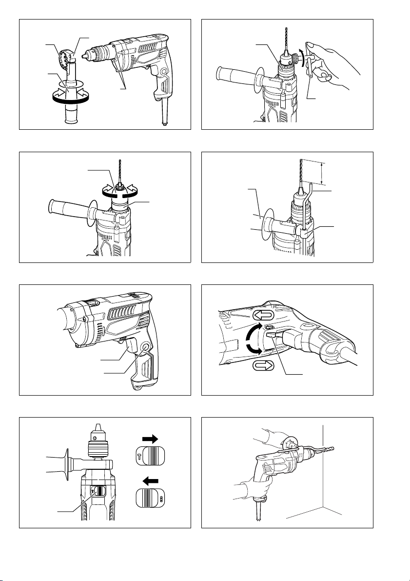
Installing side grip (auxiliary handle) (Fig. 1)
CAUTION:
• Always be sure that the tool is switched off and
unplugged before installing or removing the side grip.
Always use the side grip to ensure operating safety.
Install the side grip so that the teeth on the grip fit in
between the protrusions on the tool barrel. Then tighten
the grip by turning clockwise at the desired position. It
may be swung 360° so as to be secured at any position.
3
Page 4

Installing or removing drill bit
CAUTION:
• Always be sure that the tool is switched off and
unplugged before installing or removing the bit.
For Model M8100 (Fig. 2)
To install the bit, place it in the chuck as far as it will go.
Tighten the chuck by hand. Place the chuck key in each
of the three holes and tighten clockwise. Be sure to
tighten all three chuck holes evenly. To remove the bit,
turn the chuck key counterclockwise in just one hole,
then loosen the chuck by hand.
After using the chuck key, be sure to return it to the
original position.
For Model M8101 (Fig. 3)
Hold the ring and turn the sleeve counterclockwise to
open the chuck jaws. Place the bit in the chuck as far as
it will go. Hold the ring firmly and turn the sleeve
clockwise to tighten the chuck.
To remove the bit, hold the ring and turn the sleeve
counterclockwise.
Depth gauge (Fig. 4)
The depth gauge is convenient for drilling holes of
uniform depth. Loosen the side grip and insert the depth
gauge into the hole in the grip base. Adjust the depth
gauge to the desired depth and tighten the side grip.
NOTE:
• The depth gauge cannot be used at the position where
the depth gauge strikes against the gear housing.
FUNCTIONAL DESCRIPTION
Switch action (Fig. 5)
CAUTION:
• Before plugging in the tool, always check to see that
the switch trigger actuates properly and returns to the
“OFF” position when released.
To start the tool, simply pull the switch trigger. Tool speed
is increased by increasing pressure on the switch trigger.
Release the switch trigger to stop. For continuous
operation, pull the switch trigger, push in the lock button
and then release the switch trigger. To stop the tool from
the locked position, pull the switch trigger fully, then
release it.
Reversing switch action (Fig. 6)
This tool has a reversing switch to change the direction
of rotation. Move the reversing switch lever to the D
position (A side) for clockwise rotation or to the E
position (B side) for counterclockwise rotation.
CAUTION:
• Always check the direction of rotation before operation.
• Use the reversing switch only after the tool comes to a
complete stop. Changing the direction of rotation
before the tool stops may damage the tool.
Selecting the action mode (Fig. 7)
This tool has an action mode change lever. For rotation
with hammering, slide the action mode change lever to
the right (g symbol). For rotation only, slide the action
mode change lever to the left (m symbol).
CAUTION:
• Always slide the action mode change lever all the way
to your desired mode position. If you operate the tool
with the lever positioned halfway between the mode
symbols, the tool may be damaged.
OPERATION (Fig. 8)
Always hold the tool only by the handle when performing
an operation. Do not touch the metal part.
Hammer drilling operation
CAUTION:
• There is tremendous and sudden twisting force exerted
on the tool/bit at the time of hole break-through, when
the hole becomes clogged with chips and particles, or
when striking reinforcing rods embedded in the
concrete. Always use the side grip (auxiliary handle)
and firmly hold the tool by both side grip and switch
handle during operations. Failure to do so may result in
the loss of control of the toll and potentially serve injury.
When drilling in concrete, granite, tile, etc., slide the
action mode change lever to the position of g symbol to
use “rotation with hammering” action. Be sure to use a
tungsten-carbide tipped bit. Do not apply more pressure
when the hole becomes clogged with chips or particles.
Instead, run the tool at an idle, then remove the bit
partially from the hole. By repeating this several times,
the hole will be cleaned out.
After drilling the hole, use the blow-out bulb to clean the
dust out of the hole.
Drilling operation
When drilling in wood, metal or plastic materials, slide the
action mode change lever to the position of m symbol to
use “rotation only” action.
Drilling in wood
When drilling in wood, the best results are obtained with
wood drills equipped with a guide screw. The guide
screw makes drilling easier by pulling the bit into the
workpiece.
Drilling in metal
To prevent the bit from slipping when starting a hole,
make an indentation with a center-punch and hammer at
the point to be drilled. Place the point of the bit in the
indentation and start drilling. Use a cutting lubricant when
drilling metals. The exceptions are iron and brass which
should be drilled dry.
CAUTION:
• Pressing excessively on the tool will not speed up the
drilling. In fact, this excessive pressure will only serve
to damage the tip of your bit, decrease the tool
performance and shorten the service life of the tool.
• There is a tremendous force exerted on the tool/bit at
the time of hole break through. Hold the tool firmly and
exert care when the bit begins to break through the
workpiece.
• A stuck bit can be removed simply by setting the
reversing switch to reverse rotation in order to back
out. However, the tool may back out abruptly if you do
not hold it firmly.
• Always secure small workpieces in a vise or similar
hold-down device.
4
Page 5

MAINTENANCE
CAUTION:
• Always be sure that the tool is switched off and
unplugged before carrying out any work on the tool.
• Never use gasoline, benzine, thinner, alcohol or the
like. Discoloration, deformation or cracks may result.
To maintain product safety and reliability, repairs,
maintenance or adjustment should be carried out by a
Makita Authorized Service Center.
Noise
The typical A-weighted noise level determined according
to EN60745:
L
Sound pressure level (
Sound power level (
Uncertainty (K): 3 dB (A)
Vibration
The vibration total value (tri-axial vector sum) determined
Wear ear protection
): 98 dB (A)
pA
L
): 109 dB (A)
WA
according to EN60745:
Work mode: impact drilling into concrete
Vibration emission (
Uncertainty (K): 2.0 m/s
Work mode: drilling into metal
Vibration emission (
Uncertainty (K): 1.5 m/s
a
h, ID
a
h, D
)
: 16.5 m/s
2
): 3.0 m/s
2
2
2
• The declared vibration emission value has been
measured in accordance with the standard test method
and may be used for comparing one tool with another.
• The declared vibration emission value may also be
used in a preliminary assessment of exposure.
WARNING:
• The vibration emission during actual use of the power
tool can differ from the declared emission value
depending on the ways in which the tool is used.
• Be sure to identify safety measures to protect the
operator that are based on an estimation of exposure in
the actual conditions of use (taking account of all parts
of the operating cycle such as the times when the tool
is switched off and when it is running idle in addition to
the trigger time).
ENG905-1
ENG900-1
ENG901-1
For European countries only
ENH101-18
EC Declaration of Conformity
Makita declares that the following Machine(s):
Designation of Machine:
Hammer Drill
Model No./ Type: M8100, M8101
Conforms to the following European Directives:
2006/42/EC
They are manufactured in accordance with the following
standard or standardized documents:
EN60745
The technical file in accordance with 2006/42/EC is
available from:
Makita, Jan-Baptist Vinkstraat 2, 3070, Belgium
1.12.2014
Yasushi Fukaya
Makita, Jan-Baptist Vinkstraat 2, 3070, Belgium
Director
5
Page 6

FRANÇAIS (Instructions originales)
Descriptif
1 Embase de la poignée
2Crans
3 Poignée latérale
(poignée auxiliaire)
4 Saillie
5 Desserrer
SPÉCIFICATIONS
Modèle M8100 M8101
Capacités
Vitesse à vide (min
Cadence de frappe/mn 0 – 48 000
Longueur totale 296 mm 295 mm
Poids net 2,1 kg 2,0 kg
Catégorie de sécurité
• Étant donné l’évolution constante de notre programme
de recherche et de développement, les spécifications
contenues dans ce manuel sont sujettes à modification
sans préavis.
• Les spécifications peuvent varier suivant les pays.
• Poids selon la procédure EPTA 01/2003
Utilisations
L’outil est conçu pour le perçage avec chocs dans la
brique, le béton et la pierre, ainsi que pour le perçage
sans choc dans le bois, le métal, la céramique et le
plastique.
Alimentation
L’outil ne devra être raccordé qu’à une alimentation de la
même tension que celle qui figure sur la plaque
signalétique, et il ne pourra fonctionner que sur un
courant secteur monophasé. Réalisé avec une double
isolation, il peut de ce fait être alimenté sans mise à la
terre.
Consignes de sécurité générales pour outils
électriques
AVERTISSEMENT Veuillez lire toutes les mises
en garde et toutes les instructions. Il y a risque de
choc électrique, d’incendie et/ou de blessure grave si les
mises en garde et les instructions ne sont pas
respectées.
Conservez toutes les mises en garde et instructions
pour référence ultérieure.
CONSIGNES DE SÉCURITÉ POUR LA
PERCEUSE À PERCUSSION
1. Portez des protections d’oreilles lorsque vous
utilisez une perceuse à percussion. L’exposition
au bruit peut entraîner la surdité.
6 Serrer
7 Mandrin porte-foret
8 Clé de mandrin
9 Manchon
10 Anneau
11 Poignée latérale
Béton 16 mm
Bois 30 mm
Acier 13 mm
–1
) 0–3200
ENE039-1
ENF002-2
GEA010-1
GEB003-5
12 Tige de profondeur
13 Gâchette de l’interrupteur
14 Bouton de blocage
15 Levier inverseur
16 Levier de changement de mode
/II
2. Utilisez la ou les poignée(s) auxiliaire(s), si l’outil
en possède. La perte de contrôle comporte un
risque de blessure.
3. Saisissez l’outil électrique par ses surfaces de
poigne isolées lorsque vous effectuez une
opération au cours de laquelle l’outil tranchant
peut entrer en contact avec un câble caché ou
avec son propre cordon d’alimentation. Le
contact de l’outil tranchant avec un fil sous tension
peut mettre les parties métalliques de l’outil
électrique sous tension et causer un choc électrique
chez l’utilisateur.
4. Assurez-vous toujours de travailler en position
stable.
Lorsque vous utilisez l’outil dans un endroit
élevé, assurez-vous qu’il n’y a personne en bas.
5. Tenez l’outil fermement à deux mains.
6. Gardez les mains éloignées des pièces en
mouvement.
7. Ne laissez pas l’outil tourner. Ne le faites
fonctionner que lorsque vous le tenez.
8. Ne touchez pas le foret ou le matériau
immédiatement après l’utilisation ; ils peuvent
être extrêmement chauds et brûler votre peau.
9. Certains matériaux contiennent des produits
chimiques qui peuvent être toxiques. Prenez les
précautions nécessaires pour éviter que la
poussière dégagée lors du travail ne soit inhalée
ou n’entre en contact avec la peau. Suivez les
consignes de sécurité du fournisseur du
matériau.
CONSERVEZ CES INSTRUCTIONS.
6
Page 7

AVERTISSEMENT :
NE vous laissez PAS tromper (au fil d’une utilisation
répétée) par un sentiment d’aisance et de familiarité
avec le produit, en néglige, ant le respect rigoureux
des consignes de sécurité qui accompagnent le
produit en question. La MAUVAISE UTILISATION de
l’outil ou l’ignorance des consignes de sécurité
indiquées dans ce manuel d’instructions peut
entraîner une blessure grave.
ASSEMBLAGE
Pose de la poignée latérale (poignée auxiliaire)
(Fig. 1)
ATTENTION :
• Assurez-vous toujours que l’outil est hors tension et
débranché avant de poser ou de retirer la poignée
latérale.
Pour garantir un travail en toute sécurité, utilisez toujours
la poignée latérale. Installez la poignée latérale de façon
que les crans de la poignée s’insèrent entre les saillies
du collet de l’outil. Puis, serrez la poignée en la tournant
vers la droite sur la position voulue. Elle pivote sur 360°,
ce qui permet de la fixer à n’importe quelle position.
Installation et retrait du foret
ATTENTION :
• Vérifiez toujours que l’outil est arrêté et que son câble
d’alimentation est débranché avant d’installer ou de
retirer le foret.
Pour le modèle M8100 (Fig. 2)
Pour installer le foret, introduisez-le à fond dans le
mandrin. Serrez le mandrin à la main. Puis introduisez la
clé de mandrin dans chacun des trois trous et serrez en
tournant en sens des aiguilles d’une montre. Veillez à
bien serrer les trois trous de façon uniforme. Pour retirer
le foret, tournez la clé de mandrin en sens inverse des
aiguilles d’une montre dans l’un des trois trous
seulement, puis desserrez à la main.
Après avoir utilisé la clé de mandrin, replacez-la dans le
porte-clé.
Pour le modèle M8101 (Fig. 3)
Saisissez l’anneau et tournez le manchon en sens
inverse des aiguilles d’une montre pour ouvrir les
mâchoires du mandrin. Placez le foret dans le mandrin
en l’enfonçant le plus loin possible. Saisissez fermement
l’anneau et tournez le manchon en sens des aiguilles
d’une montre pour serrer le mandrin.
Pour retirer le foret, saisissez l’anneau et tournez le
manchon en sens inverse des aiguilles d’une montre.
Tige de profondeur (Fig. 4)
La tige de profondeur vous permet de percer des trous
de longueur uniforme. Desserrez la poignée latérale et
insérez la tige de profondeur dans l’orifice à la embase
de la poignée. Réglez la tige à la profondeur voulue puis
serrez la poignée latérale.
NOTE :
• La tige de profondeur ne pourra pas être utilisée à
l’endroit où elle bute sur le carter d’engrenage.
DESCRIPTION DU FONCTIONNEMENT
Interrupteur (Fig. 5)
ATTENTION :
• Avant de brancher l’outil, vérifiez toujours que la
gâchette de l’interrupteur fonctionne et qu’elle revient
sur la position “OFF” une fois relâchée.
Pour mettre l’outil en route, il suffit de tirer sur la gâchette
de l’interrupteur. Plus vous appuyez sur la gâchette de
l’interrupteur, plus la vitesse de l’outil augmente. Pour
arrêter l’outil, relâchez la gâchette de l’interrupteur. Pour
obtenir un fonctionnement continu, tirez sur la gâchette
de l’interrupteur, appuyez sur le bouton de blocage et
relâchez la gâchette de l’interrupteur. Pour arrêter l’outil
lorsqu’il fonctionne en continu, tirez à fond sur la
gâchette de l’interrupteur et relâchez-la.
Inverseur (Fig. 6)
Cet outil est muni d’un inverseur pour modifier le sens de
rotation. Déplacez le levier inverseur sur la position D
(côté A) pour une rotation en sens des aiguilles d’une
montre, et sur la position E (côté B) pour une rotation
en sens inverse.
ATTENTION :
• Vérifiez toujours le sens de la rotation avant d’utiliser
l’outil.
• N’utilisez l’inverseur qu’une fois l’outil parfaitement
arrêté. Sinon, vous risquez d’endommager l’outil.
Sélection du mode de fonctionnement (Fig. 7)
Cet outil est muni d’un levier de changement de mode.
Pour une rotation avec frappe, glissez ce levier vers la
droite (symbole g). Pour une rotation seulement,
glissez-le vers la gauche (symbole m).
ATTENTION :
• Glissez toujours le levier de changement de mode
complètement sur la position du mode désiré. Si vous
faites fonctionner l’outil en plaçant le levier entre les
symboles de mode, vous risquez d’endommager l’outil.
PERCAGE (Fig. 8)
Tenez toujours l’outil uniquement par sa poignée pour
travailler. Ne touchez pas la partie métallique.
Perçage avec frappe
ATTENTION :
• Une force énorme s’exerce sur le foret et l’outil lorsque
le foret émerge sur la face opposée, lorsque le trou est
encombré de copeaux ou de particules, ou lors de la
frappe sur des barres d’armature encastrées dans le
béton. Utilisez toujours la poignée latérale (poignée
auxiliaire) et tenez fermement l’outil par la poignée
latérale et par la poignée revolver lors des travaux.
Sinon, vous risquez de perdre le contrôle de l’outil et
de subir une blessure grave.
Lorsque vous percez du béton, granite, carrelage, etc.,
glissez le levier de changement de mode sur la position
du symbole g pour obtenir un mouvement de “rotation
avec frappe”. Assurez-vous d’utiliser un foret à pointe en
carbure de tungstène. N’appliquez pas davantage de
pression lorsque le trou est bouché par les copeaux et
particules. Faites plutôt tourner l’outil au ralenti, puis
retirez partiellement la mèche du trou. En répétant cette
opération quelques fois, le trou se débouchera.
Une fois le trou percé, utilisez la poire soufflante pour
retirer la poussière du trou.
7
Page 8

Perçage
Lorsque vous percez dans les matériaux de bois, de
métal ou de plastique, glissez le levier de changement de
mode sur la positon du symbole m pour obtenir un
mouvement de “rotation seulement”.
Perçage du bois
Lorsque vous percez dans du bois, vous obtiendrez de
meilleurs résultats avec des forets munis d’une vis-guide.
Celle-ci rend le perçage plus aisé en tirant le foret à
l’intérieur de la pièce.
Perçage du métal
Pour empêcher le foret de glisser en début de perçage,
faites une indentation au point de perçage à l’aide d’un
poinçon et d’un marteau. Placez ensuite la pointe du
foret dans l’indentation et commencez à percer. Quand
vous percez dans du métal, utilisez un lubrifiant. Seuls le
fer et le laiton peuvent se percer à sec.
ATTENTION :
• Une pression excessive sur l’outil n’accélère pas le
perçage. Au contraire, elle risque d’endommager la
pointe du foret, de réduire le rendement de l’outil et
donc sa durée de service.
• Une force énorme s’exerce sur le foret et l’outil quand
le premier émerge sur la face postérieure. Tenez votre
outil fermement et faites bien attention dès que le foret
commence à approcher de la face opposée du
matériau que vous percez.
• Un foret coincé peut se retirer en plaçant l’inverseur sur
la direction opposée. Il faut alors faire très attention car
l’outil risque de reculer brusquement si vous ne le
tenez pas fermement.
• Assurez toujours les petites pièces à percer à l’aide
d’un étau ou d’un mode de fixation analogue.
ENTRETIEN
ATTENTION :
• Assurez-vous toujours que l’outil est hors tension et
hors secteur avant toute intervention.
• N’utilisez jamais d’essence, benzine, diluant, alcool ou
autre produit similaire. Cela risquerait de provoquer la
décoloration, la déformation ou la fissuration de l’outil.
Pour maintenir la sécurité et la fiabilité du produit, les
réparations, l’entretien ou les réglages doivent être
effectués par le Centre d’Entretien Makita.
ENG905-1
Bruit
Niveau de bruit pondéré A typique, déterminé selon
EN60745 :
Niveau de pression sonore (
Niveau de puissance sonore (
Incertitude (K) : 3 dB (A)
Porter des protecteurs anti-bruit
Vibrations
Valeur totale de vibrations (somme de vecteur triaxial)
déterminée selon EN60745 :
Mode de travail : Perçage avec chocs dans le béton
Émission de vibrations (
Incertitude (K) : 2,0 m/s
Mode de travail : Perçage dans le métal
Émission de vibrations (
Incertitude (K) : 1,5 m/s
a
h, ID
2
a
h, D
2
L
) : 98 dB (A)
pA
L
) : 109 dB (A)
WA
) : 16,5 m/s
) : 3,0 m/s
ENG900-1
2
2
• La valeur d’émission de vibrations déclarée a été
mesurée conformément à la méthode de test standard
et peut être utilisée pour comparer les outils entre eux.
• La valeur d’émission de vibrations déclarée peut aussi
être utilisée pour l’évaluation préliminaire de
l’exposition.
ENG901-1
AVERTISSEMENT :
• L’émission de vibrations lors de l’usage réel de l’outil
électrique peut être différente de la valeur d’émission
déclarée, suivant la façon dont l’outil est utilisé.
• Les mesures de sécurité à prendre pour protéger
l’utilisateur doivent être basées sur une estimation de
l’exposition dans des conditions réelles d’utilisation (en
tenant compte de toutes les composantes du cycle
d’utilisation, comme par exemple le moment de sa
mise hors tension, lorsqu’il tourne à vide et le moment
de son déclenchement).
ENH101-18
Pour les pays d’Europe uniquement
Déclaration de conformité CE
Makita déclare que la (les) machine(s) suivante(s) :
Désignation de la machine :
Perceuse à Percussion
N° de modèle / Type : M8100, M8101
sont conformes aux directives européennes
suivantes :
2006/42/CE
et sont fabriquées conformément aux normes ou aux
documents normalisés suivants :
EN60745
La documentation technique conforme à la norme 2006/
42/CE est disponible auprès de :
Makita, Jan-Baptist Vinkstraat 2, 3070, Belgique
1.12.2014
Yasushi Fukaya
Directeur
Makita, Jan-Baptist Vinkstraat 2, 3070, Belgique
8
Page 9

DEUTSCH (Originale Anleitungen)
Übersicht
1 Griffbasis
2 Zähne
3 Seitengriff (Zusatzgriff)
4 Vorsprung
5 Lösen
6 Anziehen
TECHNISCHE DATEN
Modell M8100 M8101
Bohrleistungen
Leerlaufdrehzahl (min
Schlagzahl/min. 0 – 48.000
Gesamtlänge 296 mm 295 mm
Nettogewicht 2,1 kg 2,0 kg
Sicherheitsklasse /II
• Wir behalten uns vor, Änderungen im Zuge der
Entwicklung und des technischen Fortschritts ohne
vorherige Ankündigung vorzunehmen.
• Die technischen Daten können von Land zu Land
abweichen.
• Gewicht nach EPTA-Verfahren 01/2003
Vorgesehene Verwendung
Die Maschine ist für Schlagbohren in Ziegel, Beton und
Stein sowie für Bohren in Holz, Metall, Keramik und
Kunststoff vorgesehen.
Stromversorgung
Die Maschine darf nur an die auf dem Typenschild
angegebene Spannung angeschlossen werden und
arbeitet nur mit Einphasen-Wechselspannung. Diese
sind doppelt schutzisoliert und können daher auch an
Steckdosen ohne Erdleiter verwendet werden.
Allgemeine Sicherheitswarnungen für
Elektrowerkzeuge
WARNUNG Lesen Sie alle Sicherheitswarnungen
und Anweisungen durch. Eine Missachtung der unten
aufgeführten Warnungen und Anweisungen kann zu
einem elektrischen Schlag, Brand und/oder schweren
Verletzungen führen.
Bewahren Sie alle Warnungen und Anweisungen für
spätere Bezugnahme auf.
FÜR SCHLAGBOHRMASCHINESICHERHEITSWARNUNGEN
1. Tragen Sie Gehörschützer beim Arbeiten mit
Schlagbohrmaschinen. Lärmeinwirkung kann zu
Gehörverlust führen.
2. Benutzen Sie (einen) Zusatzgriff(e), sofern er
(sie) mit dem Werkzeug geliefert wurde(n).
Verlust der Kontrolle kann Verletzungen
verursachen.
7Bohrfutter
8 Bohrfutterschlüssel
9 Werkzeugaufnahme
10 Klemmring
11 Seitengriff
12 Tiefenanschlag
Beton 16 mm
Holz 30 mm
Stahl 13 m m
–1
)0–3.200
ENE039-1
ENF002-2
GEA010-1
GEB003-5
13 Ein-Aus-Schalter
14 Arretierknopf
15 Drehrichtungsumschalter
16 Betriebsart-Umschalthebel
3. Halten Sie Elektrowerkzeuge nur an den
isolierten Griffflächen, wenn Sie Arbeiten
ausführen, bei denen die Gefahr besteht, dass
verborgene Kabel oder das eigene Kabel
kontaktiert werden. Bei Kontakt mit einem Strom
führenden Kabel können die freiliegenden
Metallteile des Elektrowerkzeugs ebenfalls Strom
führend werden, so dass der Benutzer einen
elektrischen Schlag erleiden kann.
4. Achten Sie stets auf sicheren Stand.
Vergewissern Sie sich bei Einsatz der Maschine
an hochgelegenen Arbeitsplätzen, dass sich
keine Personen darunter aufhalten.
5. Die Maschine sicher mit beiden Händen
festhalten.
6. Halten Sie die Hände von rotierenden Teilen fern.
7. Lassen Sie die Maschine nicht unbeaufsichtigt
laufen. Benutzen Sie die Maschine nur mit
Handhaltung.
8. Vermeiden Sie eine Berührung des
Bohrereinsatzes oder des Werkstücks
unmittelbar nach der Bearbeitung, weil sie dann
noch sehr heiß sind und Hautverbrennungen
verursachen können.
9. Manche Materialien können giftige Chemikalien
enthalten. Treffen Sie Vorsichtsmaßnahmen, um
das Einatmen von Arbeitsstaub und Hautkontakt
zu verhüten. Befolgen Sie die Sicherheitsdaten
des Materialherstellers.
BEWAHREN SIE DIESE HINWEISE
SORGFÄLTIG AUF.
WARNUNG:
Lassen Sie sich NICHT durch Bequemlichkeit oder
Vertrautheit mit dem Produkt (durch wiederholten
Gebrauch erworben) von der strikten Einhaltung der
Sicherheitsregeln für das vorliegende Produkt
abhalten. MISSBRAUCH oder Missachtung der
Sicherheitsvorschriften in dieser Anleitung können
schwere Verletzungen verursachen.
9
Page 10

MONTAGE
Montieren des Seitengriffs (Zusatzgriffs) (Abb. 1)
VORSICHT:
• Vergewissern Sie sich vor der Montage oder
Demontage des Seitengriffs stets, dass die Maschine
ausgeschaltet und vom Stromnetz getrennt ist.
Verwenden Sie stets den Seitengriff, um
Betriebssicherheit zu gewährleisten. Montieren Sie den
Seitengriff so, dass die Verzahnungen von Griff und
Maschinengehäuse ineinander eingreifen. Ziehen Sie
dann den Griff fest, indem Sie ihn an der gewünschten
Position im Uhrzeigersinn drehen. Der Griff kann um
360° geschwenkt und in jeder beliebigen Position
gesichert werden.
Montage und Demontage des Bohrers
VORSICHT:
• Vergewissern Sie sich vor der Montage oder
Demontage des Einsatzwerkzeugs stets, dass die
Maschine ausgeschaltet und vom Stromnetz getrennt
ist.
Für Modell M8100 (Abb. 2)
Führen Sie das Einsatzwerkzeug zum Montieren bis zum
Anschlag in das Bohrfutter ein. Ziehen Sie das Bohrfutter
von Hand an. Setzen Sie den Bohrfutterschlüssel in
jedes der drei Löcher ein, und drehen Sie ihn im
Uhrzeigersinn. Ziehen Sie das Bohrfutter in allen drei
Löchern mit gleicher Kraft an. Führen Sie den
Bohrfutterschlüssel zum Demontieren des
Einsatzwerkzeugs nur in ein Loch ein, und drehen Sie
ihn entgegen dem Uhrzeigersinn, bevor Sie das
Bohrfutter von Hand lösen.
Bringen Sie den Bohrfutterschlüssel nach Gebrauch
wieder an seinem ursprünglichen Platz an.
Für Modell M8101 (Abb. 3)
Halten Sie den Klemmring fest, und drehen Sie die
Werkzeugverriegelung entgegen dem Uhrzeigersinn, um
die Bohrfutterbacken zu öffnen. Führen Sie das
Einsatzwerkzeug bis zum Anschlag in das Spannfutter
ein. Halten Sie den Klemmring fest, und drehen Sie die
Werkzeugverriegelung im Uhrzeigersinn, um das
Bohrfutter festzuziehen.
Zum Entfernen des Einsatzwerkzeugs halten Sie den
Klemmring und drehen die Werkzeugverriegelung
entgegen dem Uhrzeigersinn.
Tiefenanschlag (Abb. 4)
Der Tiefenanschlag ist praktisch, um Löcher von gleicher
Tiefe zu bohren. Lösen Sie den Seitengriff, und führen
Sie den Tiefenanschlag in das Loch in der Griffbasis ein.
Stellen Sie den Tiefenanschlag auf die gewünschte
Bohrtiefe ein, und ziehen Sie den Seitengriff an.
HINWEIS:
• Der Tiefenanschlag kann nicht in einer Position
verwendet werden, in der er gegen das
Getriebegehäuse stößt.
FUNKTIONSBESCHREIBUNG
Schalterfunktion (Abb. 5)
VORSICHT:
• Vergewissern Sie sich vor dem Anschließen der
Maschine an das Stromnetz stets, dass der Ein-AusSchalter ordnungsgemäß funktioniert und beim
Loslassen in die AUS-Stellung zurückkehrt.
Zum Einschalten der Maschine einfach den Ein-AusSchalter drücken. Die Drehzahl erhöht sich durch
verstärkte Druckausübung auf den Ein-Aus-Schalter.
Zum Ausschalten lassen Sie den Ein-Aus-Schalter los.
Für Dauerbetrieb betätigen Sie den Ein-Aus-Schalter,
drücken Sie den Arretierknopf hinein und lassen Sie
dann den Ein-Aus-Schalter los. Zum Ausrasten des
Arretierknopfes drücken Sie den Ein-Aus-Schalter bis
zum Anschlag hinein und lassen ihn dann los.
Drehrichtungsumschalterbedienung (Abb. 6)
Diese Maschine besitzt einen Drehrichtungsumschalter.
Stellen Sie den Drehrichtungsumschalthebel für
Rechtsdrehung auf die Stellung D (Seite A) oder für
Linksdrehung auf die Stellung E (Seite B).
VORSICHT:
• Prüfen Sie stets die Drehrichtung, bevor Sie mit der
Arbeit beginnen.
• Betätigen Sie den Drehrichtungsumschalter erst,
nachdem die Maschine völlig zum Stillstand gekommen
ist. Durch Umschalten der Drehrichtung bei noch
laufender Maschine kann die Maschine beschädigt
werden.
Wahl der Betriebsart (Abb. 7)
Diese Maschine besitzt einen BetriebsartUmschalthebel. Schieben Sie den BetriebsartUmschalthebel für Schlagbohren nach rechts
(Symbol g). Schieben Sie den BetriebsartUmschalthebel für Bohren nach links (Symbol m).
VORSICHT:
• Schieben Sie den Betriebsart-Umschalthebel immer
bis zum Anschlag auf die gewünschte Position. Wird
die Maschine bei einer Zwischenstellung des Hebels
zwischen den Betriebsartpositionen betrieben, kann sie
beschädigt werden.
BETRIEB (Abb. 8)
Halten Sie die Maschine bei der Arbeit immer nur am
Handgriff. Berühren Sie nicht den Metallteil.
Schlagbohren
VORSICHT:
• Beim Durchbruch der Bohrung, bei Verstopfung der
Bohrung mit Spänen und Partikeln, oder beim
Auftreffen auf Betonstahl wirkt eine starke, plötzliche
Drehkraft auf Maschine und Bohrer. Montieren Sie
stets den Seitengriff (Zusatzgriff), und halten Sie die
Maschine während der Arbeit mit beiden Händen an
Seitengriff und Schaltergriff fest. Eine Missachtung
dieser Vorsichtsmaßnahme kann den Verlust der
Kontrolle über die Maschine und mögliche schwere
Verletzungen zur Folge haben.
10
Page 11

Schieben Sie den Betriebsart-Umschalthebel zum
Bohren in Beton, Granit, Fliesen usw. zur Position des
Symbols g, um die Betriebsart “Schlagbohren” zu
verwenden. Verwenden Sie unbedingt einen Bohrer mit
Hartmetallspitze. Üben Sie keinen stärkeren Druck aus,
wenn das Bohrloch mit Spänen oder Bohrmehl zugesetzt
wird. Lassen Sie statt dessen die Maschine leer laufen,
und ziehen Sie dann den Bohrer teilweise aus dem
Bohrloch heraus. Durch mehrmaliges Wiederholen
dieses Vorgangs wird das Bohrloch ausgeräumt.
Blasen Sie den Staub nach dem Bohren des Lochs mit
einer Ausblaspipette aus dem Loch.
Bohren
Schieben Sie den Betriebsart-Umschalthebel zum
Bohren in Holz, Metall oder Kunststoff zur Position des
Symbols m, um die Betriebsart “Bohren” zu verwenden.
Bohren in Holz
Beim Bohren in Holz lassen sich die besten Ergebnisse
mit Holzbohrern erzielen, die mit einer Zentrierspitze
ausgestattet sind. Die Zentrierspitze erleichtert das
Bohren, da sie den Bohrer in das Werkstück hineinzieht.
Bohren in Metall
Um Abrutschen des Bohrers beim Anbohren zu
vermeiden, empfiehlt es sich, die Bohrstelle mit einem
Zentrierkörner anzukörnen. Setzen Sie dann die Spitze
des Bohrers in die Vertiefung, und beginnen Sie mit dem
Bohren. Verwenden Sie Schneidflüssigkeit beim Bohren
von Metall. Eisen und Messing sollten jedoch trocken
gebohrt werden.
VORSICHT:
• Übermäßige Druckausübung auf die Maschine bewirkt
keine Beschleunigung der Bohrleistung. Im Gegenteil;
übermäßiger Druck führt zu einer Beschädigung der
Bohrerspitze und damit zu einer Verringerung der
Bohrerstandzeit sowie zu einer Verkürzung der
Lebensdauer der Maschine.
• Beim Bohrungsdurchbruch wirkt ein hohes
Rückdrehmoment auf Maschine und Bohrer. Halten Sie
daher die Maschine mit festem Griff und lassen Sie
Vorsicht walten, wenn der Bohrer im Begriff ist, aus
dem Werkstück auszutreten.
• Ein festsitzender Bohrer lässt sich durch einfaches
Umschalten der Drehrichtung wieder herausdrehen.
Dabei sollten Sie aber die Maschine gut festhalten,
damit sie nicht ruckartig herausgestoßen wird.
• Spannen Sie kleine Werkstücke stets in einen
Schraubstock oder eine ähnliche Aufspannvorrichtung
ein.
ENG905-1
Geräusch
Typischer A-bewerteter Geräuschpegel ermittelt gemäß
EN60745:
L
Schalldruckpegel (
Schalleistungspegel (
Ungewissheit (K): 3 dB (A)
Vibration
Vibrationsgesamtwert (Drei-Achsen-Vektorsumme)
): 98 dB (A)
pA
L
): 109 dB (A)
WA
Gehörschutz tragen
ENG900-1
ermittelt gemäß EN60745:
Arbeitsmodus: Schlagbohren in Beton
Vibrationsemission (
Ungewissheit (K): 2,0 m/s
Arbeitsmodus: Bohren in Metall
Vibrationsemission (
Ungewissheit (K): 1,5 m/s
a
h, ID
a
h, D
): 16,5 m/s
2
): 3,0 m/s
2
• Der angegebene Vibrationsemissionswert wurde im
Einklang mit der Standardprüfmethode gemessen und
kann für den Vergleich zwischen Maschinen
herangezogen werden.
• Der angegebene Vibrationsemissionswert kann auch
für eine Vorbewertung des Gefährdungsgrads
verwendet werden.
WARNUNG:
• Die Vibrationsemission während der tatsächlichen
Benutzung des Elektrowerkzeugs kann je nach der
Benutzungsweise der Maschine vom angegebenen
Emissionswert abweichen.
• Identifizieren Sie Sicherheitsmaßnahmen zum Schutz
des Benutzers anhand einer Schätzung des
Gefährdungsgrads unter den tatsächlichen
Benutzungsbedingungen (unter Berücksichtigung aller
Phasen des Arbeitszyklus, wie z. B. Ausschalt- und
Leerlaufzeiten der Maschine zusätzlich zur
Betriebszeit).
2
2
ENG901-1
WARTUNG
VORSICHT:
• Vergewissern Sie sich vor der Ausführung von Arbeiten
an der Maschine stets, dass sie ausgeschaltet und vom
Stromnetz getrennt ist.
• Verwenden Sie auf keinen Fall Benzin, Benzol,
Verdünner, Alkohol oder dergleichen. Solche Mittel
können Verfärbung, Verformung oder Rissbildung
verursachen.
Um die Sicherheit und Zuverlässigkeit des Produkts zu
gewährleisten, sollten Reparatur-, Wartungs- oder
Einstellarbeiten nur von einem MakitaKundendienstzentrum ausgeführt werden.
11
Page 12

ENH101-18
Nur für europäische Länder
EG-Übereinstimmungserklärung
Makita erklärt, dass die folgende(n) Maschine(n):
Bezeichnung der Maschine:
Schlagbohrmaschine
Modell-Nr./ Typ: M8100, M8101
den folgenden europäischen Richtlinien
entsprechen:
2006/42/EG
gemäß den folgenden Standards oder standardisierten
Dokumenten hergestellt werden:
EN60745
Die technische Akte in Übereinstimmung mit 2006/42/EG
ist erhältlich von:
Makita, Jan-Baptist Vinkstraat 2, 3070, Belgien
1.12.2014
Yasushi Fukaya
Direktor
Makita, Jan-Baptist Vinkstraat 2, 3070, Belgien
12
Page 13

Makita
Jan-Baptist Vinkstraat 2, 3070, Belgium
885407-996
IDE
Makita Corporation
www.makita.com
Anjo, Aichi, Japan
 Loading...