

Page 1
T
ECHNICAL INFORMATION
PRODUCT
P 1/ 11
Model No.
Description
JV100D (VJ01
Cordless Jig Saw
*1 Model number for North and Central American countries
except Mexico and Guam
*1)
CONCEPT AND MAIN APPLICATIONS
Model JV100D (VJ01*1) has been developed as the first cordless jig saw
of the 10.8V Li-ion Cordless series.
Its main features are:
• Compact and lightweight design achieved while maintaining the power
enough to perform smooth light duty cutting
• The same mechanical parts and functions as used for AC model 4329
This product is available in the following variations.
Model No.
JV100DZ
JV100DZW
JV100DW
JV100DWW white
JV100DWE
JV100DWEW white
VJ01Z
VJ01ZW
VJ01 Makita blue
VJ01W
All models also include the accessories listed below in "Standard equipment".
Charger
Battery
type quantity
NoNo
BL1013DC10WA
NoNo No
BL1014DC10WB
No
1
2
2
Housing
color
Makita blue
white
Makita blue
Makita blue
Makita blue
white
white
Plastic
carrying
case
No
Yes
No
Yes
All countries except
North and Central
American countries
Guamare included)
North and Central
American countries
Offered to
(Mexico and
except Mexico
and Guam
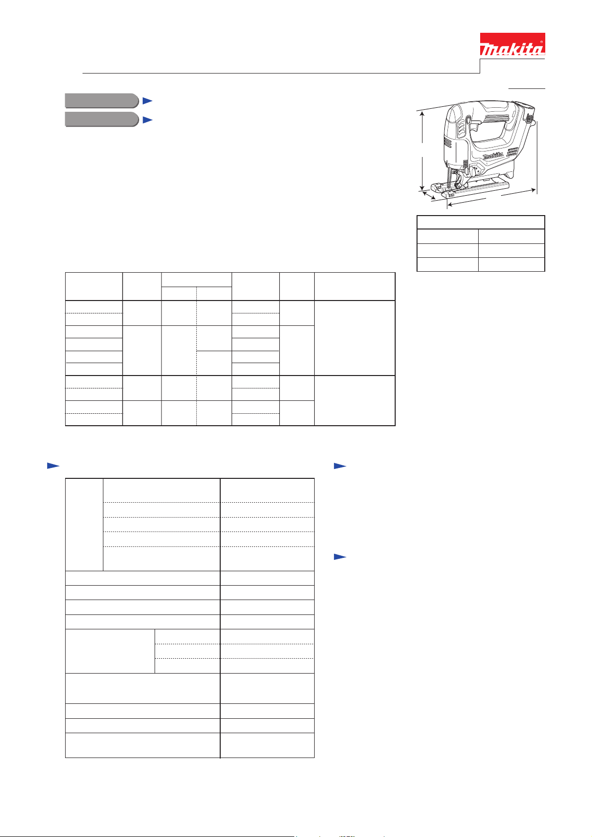
H
W
Dimensions: mm (")
Length (L)
Width (W)
Height (H)
L
231 (9-1/8)
76 (3)
196 (7-3/4)
Specification
2,
Voltage: V
Capacity: Ah
Battery
No load speed: strokes per minute
Stroke length: mm (")
Shank type
Capacities: mm (")
Cut settings
Variable speed control by trigger
Weight according to EPTA-Procedure
01/2003*
*2 For all countries except North and Central American countries
(Mexico and Guam are included.)
*3 For North and Central American countries except Mexico and Guam
*4 With battery
Energy capacity: Wh 14
Cell
Charging time
(approx.): min.
Wood
Mild steel
4: kg (lbs)
10.8*
(10.8/12V max*3)
1.3
Li-ion
50 with DC10WA*2,
(DW10WB*3)
130Max. output: W
0 - 2,400
18 (11/16)
B-type
65 (2-9/16)
2 (1/16)
4 (5/32)Aluminum
3 Orbital settings
+
Straight cutting
YesElectric brake
Yes
1.7 (3.7)
Standard equipment
Jig saw blade No. B-10 .................................. 1
Hex wrench ................................................... 1
Guide rule set (for some countries only) ........ 1
Note: The standard equipment for the tool
shown above may vary by country.
Optional accessories
Jig saw blades
Guide rule set
Hose 28
Cover plate
Kerf board set
Charger DC10WA*
Li-ion battery BL1013*2
Charger DC10WB*3
Li-ion battery BL1014*3
2
Page 2
P 2/ 11
Repair
CAUTION: Repair the machine in accordance with “Instruction manual” or “Safety instructions”.
[1] NECESSARY REPAIRING TOOLS
Code No. Description Use for
1R029 Bearing Setting Pipe 23-15.2 Pressing Bearing case complete, when assembling it to DC Motor
1R032 Bearing Setting Plate 8.2 Supporting DC Motor, when assembling it to Bearing case complete
1R258 V Block Supporting DC Motor, when assembling it to Bearing case complete
1R269 Bearing Extractor Separating DC Motor from Bearing case complete
1R274 Type 72 Field Insert Jig Supporting DC Motor, when assembling it to Bearing case complete
1R291 Retaining Ring S & R Pliers Removing /assembling Retaining ring S-6
[2] LUBRICATION
Apply Makita grease N. No.1 to the following portions designated with the black triangle to protect
parts and product from unusual abrasion.
Item No. Description AmountPortion to lubricate
20 Push plate Both side
21 Balance plate The portion that 23 Gear complete contacts
a little
a little
22 Pin 3 Whole portion
23 Gear complete Gear teeth and Armature gear in Bearing case complete and Balance plate
25 Slider guide Hole where 27 Slider reciprocates
27 Slider Elliptic hole where 37 Collar sleeve moves
33 Slider support
37 Collar sleeve Whole portion
42 Retainer complete The portion that 20 Push plate contacts
DC Motor
Bearing case
complete
Hole where 27 Slider reciprocates
Pin
a little
Approx. 3 g
a little
a little
a little
a little
a little
Dust seal
Page 3
Repair
[3] DISASSEMBLY/ASSEMBLY
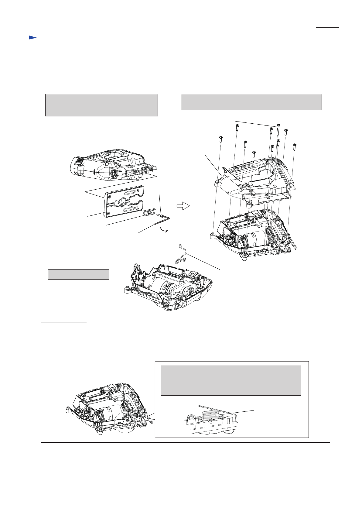
[3] -1. Housing
DISASSEMBLING
Fig. 2
P 3/ 11
1. Remove Clamp plate and Base from
Housing set by unscrewing M4x16
Hex socket head bolt with Hex wrench 3.
M4x16 Hex socket
head bolt
Base
Clamp plate
Hex wrench 3
(Standard equipment)
3. Remove Safety wire.
2. Separate Housing R by unscrewing M4x35
Tapping screw (1pc.) and 4x18 Tapping screws (9pcs).
4x35 Tapping screw (1 pc.)
4x18 Tapping screw (9 pc.)
Housing R
Safety wire
ASSEMBLING
(1) Make sure to insert Holder to Housing L (Fig. 3).
Fig. 3
Note;
Before assembling Housing R, make sure that Holder
(with M4 Screw hole) is mounted to Housing L
to fasten Housing set with M4x16 Hex socket head bolt
Holder
(2) Set Safety wire to Housing L (Fig. 2-3).
(3) Assemble Housing R to Housing L (Fig. 2-2).
(4) Assemble Base and Clamp plate to Housing set and tighten them with M4x16 Hex socket head bolt (Fig. 2-1).
Page 4
Repair
[3] DISASSEMBLY/ASSEMBLY
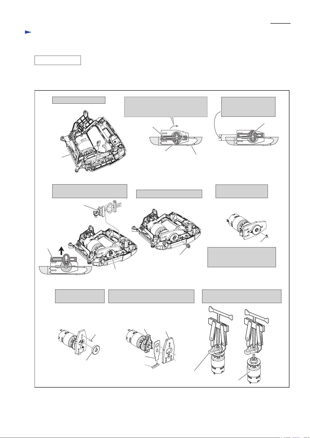
[3] -2. Reciprocating Mechanism
DISASSEMBLING
(1) Separate Housing R from Housing L (Fig. 2).
(2) Now, Reciprocating mechanism can be disassembled (Fig. 4).
Fig. 4
P 4/ 11
1. Remove Leaf spring.
Leaf spring
4. Remove Slider section from the
Collared sleeve 4.
Slider section
Slider
2. Turn DC motor shaft to move
Collared sleeve 4 up to the top
position of Slider’s elliptical hole.
Collared sleeve 4
Slider
Collared
sleeve 4
5 . Remove Collared sleeve 4.
Collared sleeve 4
Housing L
3. A space for removing
Slider from Collared
sleeve 4 is secured.
Collared
sleeve 4
6 . Remove Retaining
ring S-6 with 1R291.
Retaining ring S-6
Note;
Retaining ring S-6 is deformed
in this step. Do not re-use it.
7. Now, remove Gear
complete and Pin 3.
Pin 3
Gear complete
8. Remove Balance plate and Push plate
from Bearing case complete.
Bearing case
complete
Push plate
Dust seal
Balance plate
Bearing case
complete
9. Remove DC motor from Bearing
case complete with 1R269.
DC motor
Page 5

Repair
[3] DISASSEMBLY/ASSEMBLY
[3] -2. Reciprocating Mechanism
ASSEMBLING
(1) Assemble Bearing case complete to DC motor (Fig. 5).
Fig. 5
P 5/ 11
1. Put 1R274 onto 1R032 and set
DC motor to the 1R274. Then,
put 1R258(2pcs) to support the
DC motor.
1R274
(for protect Motor’s
terminals)
1R032
1R258
(2 pcs)
1R274
(for protect Motor’s
terminals)
1R032
2. Set Bearing case complete on DC motor and put
1R029 onto Bearing case complete. Press 1R029 to
assemble Bearing case complete to DC motor
with Arbor press.
1R029
Bearing case
complete
1R258
(2 pcs)
Note;
Press Bearing case complete with Arbor press softly and
do not press further when it is stopped.
Otherwise, the position of Pinion gear on the DC motor
may deviate.
(2) Insert Push plate into dust seal and assemble Push plate to Bearing case complete.
And then, mount Balance plate (Fig. 4).
(3) Assemble Gear complete to the pin on the Bearing case complete (Fig. 4-7).
Note;
Shake Push plate up and down while pressing Gear complete to insert it completely and to have the assembling groove
of Retaining ring S-6 on the Pin of Bearing case complete. Fix Retaining ring S-6 to secure Gear complete
to the pin’s groove (Fig. 6).
Fig. 6
1. Shake Push plate up and
down while pressing Gear
complete toward Balance
plate.
2. Now, the assembling Groove
on Pin comes into your sight.
3. Fix a new Retaining ring S-6
with 1R291.
Retaining ring S-6
Gear complete
Balance plate
4. Facing the flange side to Gear complete,
assemble Collared sleeve 4.
Brim portion
Gear complete
Collared sleeve 4
Page 6

P 6/ 11
Repair
[3] DISASSEMBLY/ASSEMBLY
[3] -2. Reciprocating Mechanism (cont.)
ASSEMBLING
(4) After setting DC motor and Reciprocating mechanism to Housing L, assemble Slider section and Leaf spring (Fig. 7).
Fig. 7
5. Make sure to insert O ring 5 into the bottom of
assembling holes for Slider guide.
O Ring 5
Housing L
Housing R
Assembling holes
7. Assemble Slider with Seal plate, Slider support
and Slider guide to Housing L while inserting
the elliptical hole of Slider into Collard sleeve 4.
6. Turn DC motor shaft to move Collared sleeve 4 to
the top position so as to reserve the space for
assembling Slider section.
8. Facing the flat side of Leaf spring to
the front, insert it into the assembly
hole discribed below vertically.
Holder
Collared
sleeve 4
Seal plate
Slider support
Elliptical hole
Slider
Slider guide
Retainer
complete
9. Make sure to put Holder and Retainer
complete in Housing L before mounting
Housing R.
Page 7

Repair
[3] DISASSEMBLY/ASSEMBLY
[3] -2. Reciprocating Mechanism
ASSEMBLING
(5) Assemble Housing R (Fig. 8).
Fig. 8
P 7/ 11
10. Mount Change lever to the Switch
while inserting the protrusion of Switch
into the hole of Change lever.
Change lever
Housing R
11. Assemble Housing R while
inserting Change lever into
the assembling hole.
Change lever
[3] -3. Lever 19
DISASSEMBLING
(1) After separating Housing R, remove DC motor and Reciprocating mechanism from Housing L.
So, the stem of Lever 19 comes into your sight. Now, Lever 19 can be disassembled by removing Stop ring E-4
(Fig. 9).
Fig. 9
1. Remove Stop ring E-4 from
the stem of Lever 19.
DC motor
Stop ring E-4
Stem of
Lever 19
ASSEMBLING
Take the reverse step of Disassembling (Fig. 9).
Reciprocating
mechanism
Housing L
Compression
Spring 4
Steel ball 4
2. Pull off the Lever 19 while paying attention not
to lose Steel ball 4 and Compression spring 14.
Housing L
Lever 19
Page 8

Circuit diagram
Fig. D-1
For the countries where the regulations for radio interference suppression are required.
Color index of lead wires' sheath
Black
Red
Orange
P 8/ 11
Switch
Line Filter
Red dot mark for + terminal
Terminal
DC Motor
Wiring diagram
Connect Lead wires to Switch, DC motor and Terminal as described in Fig. D-2.
Fig. D-2
For the countries where the regulations for radio interference suppression are required.
Face the terminals of M1, M2 to Housing L side and connect Lead wires (orange) and (black)
with terminals of Switch correctly in order to set Switch exactly in the Housing L.
Note; Do not overlap the Lead wires on the Switch body where they contact to Housing L.
Switch
NG
Housing
L side
Connect Flag terminals of the Lead wires to terminals of DC motor and route the Lead wires through Line filter.
Handle side Handle side
DC Motor
Housing L side
Housing L side
Housing
L side
NG
Terminal
Line filter
Lead wire (red)
Connect the Lead wire (red)
at described direction.
Red dot mark
Line filter
Housing L side
Page 9

Wiring diagram
Fig. D-3
For the countries where the regulations for radio interference suppression are required.
Store Lead wires in these Lead wire holders so as not to
protrude and interfere with Housing R when assembled.
P 9/ 11
Do not overlap the Lead wires under Switch (Fig. D-2).
Line filter
Locate the Red dot mark
to Handle side when
installing DC motor into
Housing L (Fig. D-2).
Switch
Route all Lead wires to Switch from
DC motor in this slot of Rib when
Line filter is used. Note; Route
a black lead wire in this slot of Rib
Rib
when Line filter is not used.
Housing L
Page 10

Circuit diagram
Fig. D-1A
For the countries where the regulations for radio interference suppression are not required.
Color index of lead wires' sheath
Black
Red
Orange
P 10/ 11
Switch
Red dot mark for + terminal
Terminal
DC Motor
Wiring diagram
Connect Lead wires to Switch, DC motor and Terminal as described in Fig. D-2A.
Fig. D-2A
For the countries where the regulations for radio interference suppression are not required.
Face the terminals of M1, M2 to Housing L side and connect Lead wires (orange) and (black)
with terminals of Switch correctly in order to set Switch exactly in the Housing L.
Note; Do not overlap the Lead wires on the Switch body where they contact to Housing L.
Switch
Housing L side
Connect Flag terminals of the Lead wires to terminals of DC motor at described direction.
Handle side Handle side
Housing L side
DC Motor
Housing L side
NG
Housing L side
NG
Terminal
Red dot mark
Connect the Lead wire (red)
at described direction.
Lead wire (red)
Housing L side
Page 11

Wiring diagram
Fig. D-3A
For the countries where the regulations for radio interference suppression are not required.
P 11/ 11
Store Lead wires in these Lead wire holders so as not to
protrude and interfere with Housing R when assembled.
Route a black lead wire in this slot
Rib
of Rib when Line filter is not used.
Line filter
Locate the Red dot mark
to Handle side when
installing DC motor into
Housing L (Fig. D-2A).
Do not overlap the Lead wires
under Switch (Fig. D-2A).
Switch
Housing
L side
 Loading...