

Page 1
GB Jig Saw Instruction Manual
JV0600
F Scie Sauteuse Manuel d’instructions
D Stichsäge Betriebsanleitung
I Seghetto alternativo Istruzioni per l’uso
NL Decoupeerzaag Gebruiksaanwijzing
E Sierra Caladora Manual de instrucciones
P Serra Tico-Tico Manual de instruções
DK Dekupørsav Brugsanvisning
GR
Παλινδρομικό πριόνι Οδηγίες χρήσεως
Page 2
12
10
11
9
5
6
7
8
4
2
3
1
011956
011957
3
011958
4
56
012053
011959
011960
2
Page 3
78
12
13
11
14
13
15
16
13
11
14
17
011961
011962
910
11 12
011963
011965 011966
13 14
011967
011964
011968
3
Page 4
15 16
18
19
14
20
11
19
21
22
19
20
19
23
24
25
24
011969
011970
17 18
19 20
011971
011973
011975
21
4
011972
011974
Page 5

ENGLISH (Original instructions)
Explanation of general view
1 Cutting action changing lever
2 Switch trigger
3 Lock button
4 Speed adjusting dial
5 Blade holder
6Blade
7 Fixed position
8 Released position
9 Blade clamp lever
SPECIFICATIONS
Model JV0600
Length of stroke 23 mm
Blade type B type
Max. cutting capacities
Strokes per minute (min
Overall length 236 mm
Net weight 2.4 kg
Safety class /II
• Due to our continuing programme of research and
development, the specifications herein are subject to
change without notice.
• Specifications may differ from country to country.
• Weight according to EPTA-Procedure 01/2003
ENE019-1
Intended use
The tool is intended for the sawing of wood, plastic and
metal materials. As a result of the extensive accessory
and saw blade program, the tool can be used for many
purposes and is very well suited for curved or circular
cuts.
ENF002-1
Power supply
The tool should be connected only to a power supply of
the same voltage as indicated on the nameplate, and can
only be operated on single-phase AC supply.
They are double-insulated in accordance with European
Standard and can, therefore, also be used from sockets
without earth wire.
General Power Tool Safety Warnings
WARNING Read all safety warnings and all
instructions. Failure to follow the warnings and instruc-
tions may result in electric shock, fire and/or serious
injury.
Save all warnings and instructions for future reference.
10 Wrench holder
11 Hex wrench
12 Cutting line
13 Base
14 Bolt
15 Edge
16 Graduation
17 Starting hole
18 Hose
Wood 90 mm
Mild steel 10 mm
–1
) 500 – 3,100
GEA010-1
19 Rip fence (Guide rule)
20 Fence guide
21 Threaded knob
22 Pin
23 Anti-splintering device
24 Tool base
25 Cover plate
GEB016-3
JIG SAW SAFETY WARNINGS
1. Hold power tool by insulated gripping surfaces
when performing an operation where the cutting
tool may contact hidden wiring or its own cord.
Cutting accessory contacting a “live” wire may make
exposed metal parts of the power tool “live” and
could give the operator an electric shock.
2. Use clamps or another practical way to secure
and support the workpiece to a stable platform.
Holding the work by hand or against your body
leaves it unstable and may lead to loss of control.
3. Always use safety glasses or goggles. Ordinary
eye or sun glasses are NOT safety glasses.
4. Avoid cutting nails. Inspect workpiece for any
nails and remove them before operation.
5. Do not cut oversize workpiece.
6. Check for the proper clearance beyond the workpiece before cutting so that the blade will not
strike the floor, workbench, etc.
7. Hold the tool firmly.
8. Make sure the blade is not contacting the workpiece before the switch is turned on.
9. Keep hands away from moving parts.
10. Do not leave the tool running. Operate the tool
only when hand-held.
11. Always switch off and wait for the blade to come
to a complete stop before removing the blade
from the workpiece.
12. Do not touch the blade or the workpiece immediately after operation; they may be extremely hot
and could burn your skin.
13. Do not operate the tool at no-load unnecessarily.
5
Page 6

14. Some material contains chemicals which may be
toxic. Take caution to prevent dust inhalation
and skin contact. Follow material supplier safety
data.
15. Always use the correct dust mask/respirator for
the material and application you are working
with.
WARNING:
DO NOT let comfort or familiarity with product
(gained from repeated use) replace strict adherence
to safety rules for the subject product.
MISUSE or failure to follow the safety rules stated in
this instruction manual may cause serious personal
injury.
SAVE THESE INSTRUCTIONS.
FUNCTIONAL DESCRIPTION
CAUTION:
• Always be sure that the tool is switched off and unplugged before adjusting or checking function on the tool.
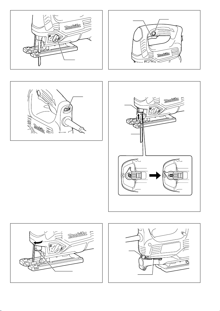
Selecting the cutting action (Fig. 1)
This tool can be operated with an orbital or a straight line (up and down) cutting action. The orbital cutting action
thrusts the blade forward on the cutting stroke and greatly increases cutting speed.
To change the cutting action, just turn the cutting action changing lever to the desired cutting action position.
Refer to the table to select the appropriate cutting action.
Position Cutting action Applications
0 Straight line cutting action
I Small orbit cutting action For cutting mild steel, aluminum and hard wood.
II Medium orbit cutting action
III Large orbit cutting action For fast cutting in wood and plywood.
For cutting mild steel, stainless steel and plastics.
For clean cuts in wood and plywood.
For cutting wood and plywood.
For fast cutting in aluminum and mild steel.
Switch action (Fig. 2)
CAUTION:
• Before plugging in the tool, always check to see that
the switch trigger actuates properly and returns to the
“OFF” position when released.
• Switch can be locked in “ON” position for ease of operator comfort during extended use. Apply caution when
locking tool in “ON” position and maintain firm grasp on
tool.
To start the tool, simply pull the switch trigger. Release
the switch trigger to stop.
For continuous operation, pull the switch trigger and then
push in the lock button.
To stop the tool from the locked position, pull the switch
trigger fully, then release it.
6
Speed adjusting dial (Fig. 3)
The tool speed can be infinitely adjusted by turning the
speed adjusting dial. Higher speed is obtained when the
speed adjusting dial is turned in the direction of number
5; lower speed is obtained when it is turned in the direction of number 1.
Refer to the table to select the proper speed for the workpiece to be cut. However, the appropriate speed may differ with the type or thickness of the workpiece. In
general, higher speeds will allow you to cut workpieces
faster but the service life of the blade will be reduced.
Workpiece to be cut Number on adjusting dial
Wood 4 – 5
Mild steel 3 – 5
Stainless steel 3 – 4
Aluminum 3 – 5
Plastics 1 – 4
Page 7

CAUTION:
• The speed adjusting dial can be turned only as far as 5
and back to 1. Do not force it past 5 or 1, or the speed
adjusting function may no longer work.
ASSEMBLY
CAUTION:
• Always be sure that the tool is switched off and
unplugged before carrying out any work on the tool.
Installing or removing saw blade (Fig. 4 & 5)
CAUTION:
• Always clean out all chips or foreign matter adhering to
the blade and/or blade holder. Failure to do so may
cause insufficient tightening of the blade, resulting in a
serious personal injury.
• Do not touch the blade or the workpiece immediately
after operation; they may be extremely hot and could
burn your skin.
• Use only B type blades. Using blades other than B type
blades causes insufficient tightening of the blade,
resulting in a serious personal injury.
• When you remove the saw blade, be careful not to hurt
your fingers with the top of the blade or the tips of workpiece.
Before installing the blade, make sure that the blade
clamp lever is in the released position.
To install the blade, insert the blade (teeth facing forward)
into the blade holder until it latches. The lever moves to
the fixed position by itself and the blade is locked. Pull
the blade lightly to make sure that the blade does not fall
off during operation.
CAUTION:
• If the lever does not move to the fixed position by itself,
the blade is not installed completely. Do not press the
lever by hand to the fixed position. It may damage the
tool. Make sure that the back edge of the blade fits into
the roller.
To remove the blade, push the lever forward as far as it
will go. This allows the blade to be released.
Hex wrench storage (Fig. 6)
When not in use, store the hex wrench as shown in the
figure to keep it from being lost.
OPERATION
CAUTION:
• Always hold the base flush with the workpiece. Failure
to do so may cause blade breakage, resulting in a serious injury.
• Advance the tool very slowly when cutting curves or
scrolling. Forcing the tool may cause a slanted cutting
surface and blade breakage.
• Hold the tool firmly with one hand on the main handle
when performing the tool. If necessary, the front part of
the tool may be supported by the other hand.
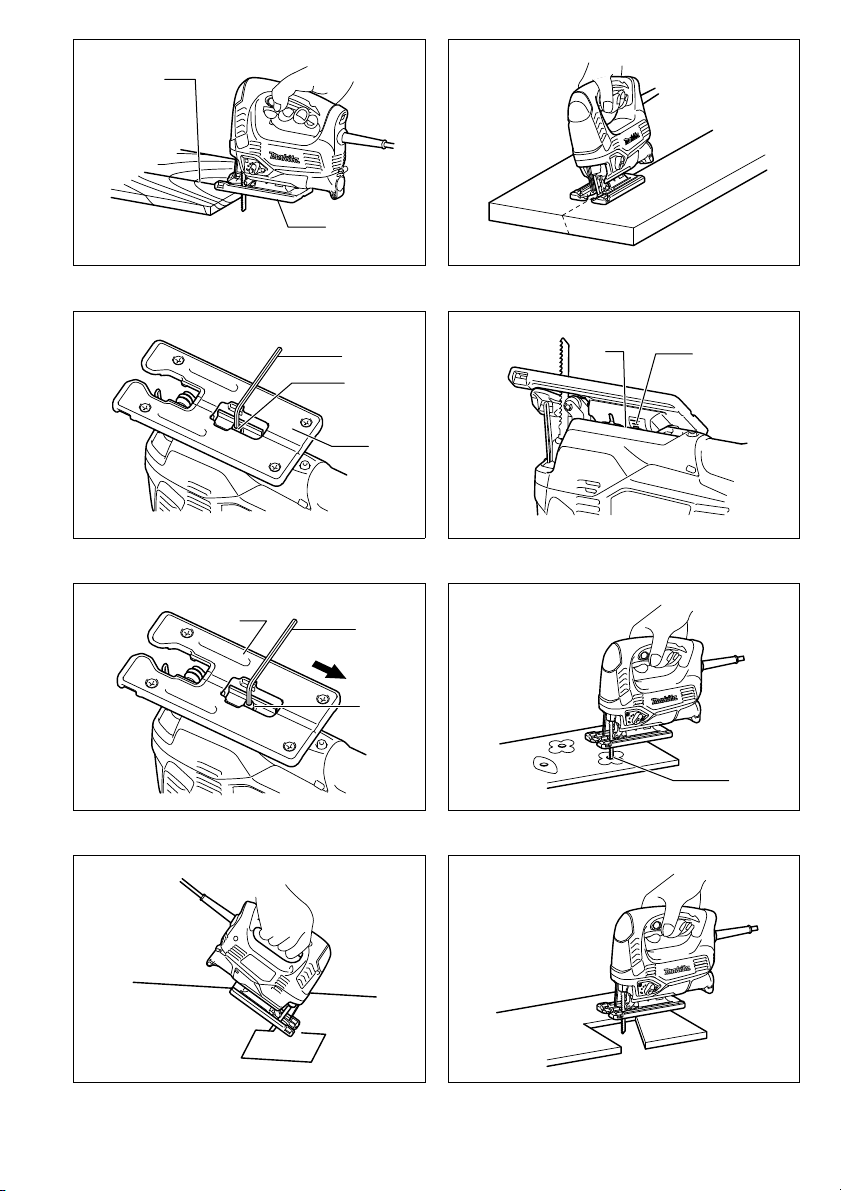
Turn the tool on without the blade making any contact
and wait until the blade attains full speed. (Fig. 7)
Then rest the base flat on the workpiece and gently move
the tool forward along the previously marked cutting line.
Bevel cutting (Fig. 8, 9 & 10)
CAUTION:
• Always be sure that the tool is switched off and
unplugged before tilting the tool base.
With the base tilted, you can make bevel cuts at any
angle between 0° and 45° (left or right).
Loosen the bolt on the back of the base with the hex
wrench. Move the base so that the bolt is positioned in
the center of the cross-shaped slot in the base.
Tilt the base until the desired bevel angle is obtained.
The edge of the housing indicates the bevel angle by
graduations. Then tighten the bolt to secure the base.
Front flush cuts (Fig. 11)
Loosen the bolt on the back of the tool base with the hex
wrench, and slide the base all the way back. Then tighten
the bolt to secure the tool base.
Cutouts
Cutouts can be made with either of two methods A or B.
A) Boring a starting hole
For internal cutouts without a lead-in cut from an
edge, pre-drill a starting hole 12 mm or more in diameter. Insert the blade into this hole to start your cut.
(Fig. 12)
B) Plunge cutting
You need not bore a starting hole or make a lead-in
cut if you carefully do as follows.
1. Tilt the tool up on the front edge of the base with
the blade point positioned just above the workpiece surface. (Fig. 13)
2. Apply pressure to the tool so that the front edge of
the base will not move when you switch on the tool
and gently lower the back end of the tool slowly.
3. As the blade pierces the workpiece, slowly lower
the base of the tool down onto the workpiece surface.
4. Complete the cut in the normal manner.
Finishing edges (Fig. 14)
To trim edges or make dimensional adjustments, run the
blade lightly along the cut edges.
Metal cutting
Always use a suitable coolant (cutting oil) when cutting
metal. Failure to do so will cause significant blade wear.
The underside of the workpiece can be greased instead
of using a coolant.
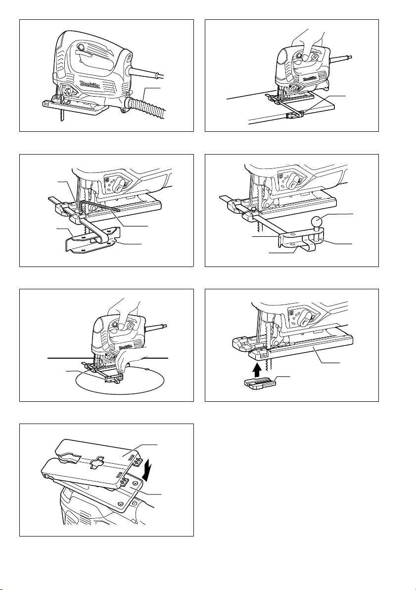
Dust extraction (Fig.15)
Clean cutting operations can be performed by connecting this tool to a Makita vacuum cleaner. Insert the hose
of the vacuum cleaner into the hole at the rear of the tool.
Rip fence (Optional accessory)
CAUTION:
• Always be sure that the tool is switched off and
unplugged before installing or removing accessories.
1) Straight cuts (Fig. 16 & 17)
When repeatedly cutting widths of 160 mm or less,
use of the rip fence will assure fast, clean, straight
cuts.
To install, insert the rip fence into the rectangular
hole on the side of the base with the fence guide facing down. Slide the rip fence to the desired cutting
width position, then tighten the bolt to secure it.
7
Page 8

2) Circular cuts (Fig. 18 & 19)
When cutting circles or arcs of 170 mm or less in
radius, install the rip fence as follows.
Insert the rip fence into the rectangular hole on the
side of the base with the fence guide facing up.
Insert the circular guide pin through either of the two
holes on the fence guide. Screw the threaded knob
onto the pin to secure the pin.
Now slide the rip fence to the desired cutting radius,
and tighten the bolt to secure it in place. Then move
the tool base all the way forward.
NOTE:
• Always use blades No. B-17, B-18, B-26 or B-27 when
cutting circles or arcs.
Anti-splintering device (Optional accessory)
(Fig. 20)
For splinter-free cuts, the anti-splintering device can be
used. To install the anti-splintering device, move the tool
base all the way forward and fit it from the back of tool
base. When you use the cover plate, install the anti-splintering device onto the cover plate.
CAUTION:
• The anti-splintering device cannot be used when making bevel cuts.
Cover plate (Optional accessory) (Fig. 21)
Use the cover plate when cutting decorative veneers,
plastics, etc. It protects sensitive or delicate surfaces
from damage. Fit it on the back of the tool base.
MAINTENANCE
CAUTION:
• Always be sure that the tool is switched off and
unplugged before attempting to perform inspection or
maintenance.
• Never use gasoline, benzine, thinner, alcohol or the
like. Discoloration, deformation or cracks may result.
To maintain product SAFETY and RELIABILITY, repairs,
carbon brush inspection and replacement, any other
maintenance or adjustment should be performed by
Makita Authorized Service Centers, always using Makita
replacement parts.
OPTIONAL ACCESSORIES
CAUTION:
• These accessories or attachments are recommended
for use with your Makita tool specified in this manual.
The use of any other accessories or attachments might
present a risk of injury to persons. Only use accessory
or attachment for its stated purpose.
If you need any assistance for more details regarding
these accessories, ask your local Makita service center.
• Jig saw blades
• Hex wrench 3
• Rip fence (guide rule) set
• Anti-splintering device
• Hose (For vacuum cleaner)
• Cover plate
NOTE:
• Some items in the list may be included in the tool package as standard accessories. They may differ from
country to country.
ENG905-1
Noise
The typical A-weighted noise level determined according
to EN60745:
Sound pressure level (L
Sound power level (L
Uncertainty (K): 3 dB (A)
Vibration
The vibration total value (tri-axial vector sum) determined
according to EN60745:
Work mode: cutting boards
Vibration emission (
Wear ear protection
Uncertainty (K): 1.5 m/s
Work mode: cutting sheet metal
Vibration emission (
Uncertainty (K): 1.5 m/s
• The declared vibration emission value has been measured in accordance with the standard test method and
may be used for comparing one tool with another.
• The declared vibration emission value may also be
used in a preliminary assessment of exposure.
pA
): 96 dB (A)
WA
a
): 10.5 m/s
h, B
2
a
): 5.5 m/s
h, M
2
): 85 dB (A)
ENG900-1
2
2
ENG901-1
WARNING:
• The vibration emission during actual use of the power
tool can differ from the declared emission value
depending on the ways in which the tool is used.
• Be sure to identify safety measures to protect the operator that are based on an estimation of exposure in the
actual conditions of use (taking account of all parts of
the operating cycle such as the times when the tool is
switched off and when it is running idle in addition to
the trigger time).
ENH101-15
For European countries only
EC Declaration of Conformity
We Makita Corporation as the responsible manufacturer declare that the following Makita machine(s):
Designation of Machine: Jig Saw
Model No./ Type: JV0600
are of series production and
Conforms to the following European Directives:
2006/42/EC
And are manufactured in accordance with the following
standards or standardised documents:
EN60745
The technical documentation is kept by our authorized
representative in Europe who is:
Makita International Europe Ltd.
Michigan Drive, Tongwell,
Milton Keynes, Bucks MK15 8JD, England
18.11.2010
Tomoyasu Kato
Director
Makita Corporation
3-11-8, Sumiyoshi-cho,
Anjo, Aichi, 446-8502, JAPAN
8
Page 9

NEDERLANDS (Originele instructies)
Verklaring van algemene gegevens
1 Zaagactie-keuzehendel
2 Trekkerschakelaar
3 Vastzetknop
4 Snelheidsregelknop
5 Zaagbladhouder
6 Zaagblad
7 Vaste stand
8 Losgezette stand
9 Zaagbladklemhendel
TECHNISCHE GEGEVENS
Model JV0600
Slaglengte 23 mm
Type zaagblad Type B
Max. snijcapaciteit
Aantal slagen per minuut (min
Totale lengte 236 mm
Nettogewicht 2,4 kg
Veiligheidsklasse /II
• In verband met ononderbroken research en ontwikkeling behouden wij ons het recht voor bovenstaande
technische gegevens te wijzigen zonder voorafgaande
kennisgeving.
• De technische gegevens kunnen van land tot land verschillen.
• Gewicht volgens de EPTA-procedure 01/2003
Doeleinden van gebruik
Dit gereedschap is bedoeld voor het zagen van hout,
kunststof en metalen materialen. Een uitgebreide keuze
van accessoires en zaagbladen staat ter beschikking,
zodat het gereedschap voor talrijke doeleinden kan worden gebruikt en optimaal geschikt is voor het zagen van
bogen en cirkels.
Stroomvoorziening
Het gereedschap mag alleen worden aangesloten op
een stroombron van hetzelfde voltage als aangegeven
op de naamplaat, en kan alleen op enkel-fase wisselstroom worden gebruikt.
Het gereedschap is dubbel-geïsoleerd volgens de Europese standaard en kan derhalve ook op een niet-geaard
stopcontact worden aangesloten.
10 Sleutelhouder
11 Inbussleutel
12 Zaaglijn
13 Voet
14 Bout
15 Zijrand
16 Schaalverdelingen
17 Startgaatje
18 Slang
Hout 90 mm
Zacht staal 10 mm
–1
) 500 – 3 100
ENE019-1
ENF002-1
19 Breedtegeleider
(trekgeleiderset)
20 Geleider
21 Schroefknop
22 Pen
23 Antisplinterinrichting
24 Gereedschapsvoet
25 Dekplaat
Algemene veiligheidswaarschuwingen voor
elektrisch gereedschap
WAARSCHUWING! Lees alle veiligheidswaar-
schuwingen en alle instructies. Het niet volgen van de
waarschuwingen en instructies kan leiden tot elektrische
GEA010-1
schokken, brand en/of ernstig letsel.
Bewaar alle waarschuwingen en instructies om in de
toekomst te kunnen raadplegen.
GEB016-3
VEILIGHEIDSVOORSCHRIFTEN VOOR DE
DECOUPEERZAAG
1. Houd elektrisch gereedschap vast aan het geïsoleerde oppervlak van de handgrepen wanneer u
werkt op plaatsen waar het slijpaccessoire met
verborgen bedrading of zijn eigen snoer in aanraking kan komen.
aanraking komen met onder spanning staande draden, zullen de niet-geïsoleerde metalen delen van het
gereedschap onder spanning komen te staan zodat
de gebruiker een elektrische schok kan krijgen.
2. Gebruik klemmen of een andere praktische
methode om het werkstuk op een stabiele ondergrond te bevestigen en ondersteunen. Als u het
werkstuk in uw hand of tegen uw lichaam geklemd
houdt, is het onvoldoende stabiel en kunt u de controle erover verliezen.
3. Draag altijd een veiligheidsbril. Een gewone bril
of een zonnebril is GEEN veiligheidsbril.
4. Vermijd het zagen op spijkers. Inspecteer het
werkstuk vooraf op de aanwezigheid van spijkers en verwijder deze voordat u met het werk
begint.
Wanneer het booraccessoire in
24
Page 10

5. Ook niet voor het zagen van zeer grote werkstukken.
6. Controleer vooraf of er voldoende vrije ruimte is
achter het werkstuk om te voorkomen dat het
zaagblad tegen een vloer, een werkbank e.d.
stoot.
7. Houd het gereedschap stevig vast.
8. Zorg ervoor dat het zaagblad niet in contact is
met het werkstuk voordat u de spanning inschakelt.
9. Houd uw handen uit de buurt van de bewegende
delen.
10. Schakel altijd het gereedschap uit als u weg
moet. Schakel het gereedschap alleen in als u
het in handen houdt.
11. Schakel altijd uit en wacht tot het zaagblad volledig tot stilstand is gekomen, alvorens het
gereedschap van het werkstuk te verwijderen.
12. Raak onmiddellijk na gebruik het zaagblad of het
werkstuk niet aan, aangezien het nog gloeiend
heet kan zijn en brandwonden kan veroorzaken.
13. Laat het gereedschap niet onnodig onbelast
draaien.
14. Sommige materialen bevatten chemische stoffen
die vergiftig kunnen zijn. Vermijd inademing van
stof en contact met de huid. Volg de veiligheidsinstructies van de leverancier van het materiaal.
15. Gebruik altijd het juiste stofmasker/ademhalingsapparaat voor het materiaal en de toepassing waarmee u werkt.
BEWAAR DEZE VOORSCHRIFTEN.
WAARSCHUWING:
LAAT U NIET misleiden door een vals gevoel van
comfort en vertrouwdheid met het gereedschap (na
veelvuldig gebruik) en neem alle veiligheidsvoorschriften van het betreffende gereedschap altijd
strikt in acht.
VERKEERD GEBRUIK of het niet naleven van de veiligheidsvoorschriften in deze gebruiksaanwijzing
kan leiden tot ernstige verwondingen.
BESCHRIJVING VAN DE FUNCTIES
LET OP:
• Zorg altijd dat het gereedschap is uitgeschakeld en niet op een stopcontact is aangesloten voordat u functies op het
gereedschap instelt of controleert.
Selecteren van de zaagactie (Fig. 1)
Dit gereedschap kan met twee zaagacties worden gebruikt: Zagen in een cirkelbaan of in rechte lijn (op en neer). Tijdens zagen in een cirkelbaan, wordt het zaagblad door de zaagactie naar voren geduwd en vermeerdert de zaagsnelheid aanzienlijk.
Om de zaagactie te veranderen, draait u gewoon de zaagactie-keuzehendel naar de gewenste stand.
Zie de tabel om de juiste zaagwerking te kiezen.
Stand Zaagactie Toepassingen
0 Zagen in rechte lijn
I Zagen in kleine cirkelbaan Zagen van zacht staal, aluminium en hard hout.
II Zagen in middelgrote cirkelbaan
III Zagen in grote cirkelbaan Snel zagen in hout en gelaagd hout.
Zagen van zacht staal, roestvrij staal en plastic.
Schoon zagen van hout en gelaagd hout.
Zagen van hout en gelaagd hout.
Snel zagen in aluminium en zacht staal.
Werking van de schakelaar (Fig. 2)
LET OP:
• Alvorens het netsnoer op het stopcontact aan te sluiten, dient u altijd te controleren of de trekkerschakelaar
juist werkt en bij loslaten naar de “OFF” positie terugkeert.
• De schakelaar kan worden vastgezet in de “AAN”
stand, voor het gemak van de gebruiker bij langdurig
gebruik. Wees extra voorzichtig wanneer het gereedschap in de “AAN” stand is vastgezet en houd het
gereedschap altijd stevig vast.
Om het gereedschap te starten, drukt u gewoon de trekkerschakelaar in. Laat de trekkerschakelaar los om het
gereedschap te stoppen.
Voor langdurig zagen drukt u eerst de trekkerschakelaar
en dan de vastzetknop in.
Om het gereedschap vanuit deze vergrendelde stand te
stoppen, wordt de trekkerschakelaar helemaal ingedrukt
en vervolgens losgelaten.
Snelheidsregelknop (Fig. 3)
De snelheid van het gereedschap is traploos regelbaar
met de snelheidsregelknop. Een hogere snelheid kiest u
door de snelheidsregelknop in de richting van de 5 te
draaien; een lagere snelheid door de knop in de richting
van de 1 te draaien.
Raadpleeg de tabel voor het selecteren van de snelheid
die geschikt is voor het te zagen werkstuk. De geschikte
snelheid hangt echter ook af van het type of de dikte van
het werkstuk. In het algemeen, kunt u met hogere snelheden sneller zagen, maar het zaagblad zal dan minder
lang meegaan.
Te zagen werkstuk Nummer op regelknop
Hout 4–5
Zacht staal 3 – 5
Roestvrij staal 3 – 4
Aluminium 3 – 5
Plastic 1–4
25
Page 11

LET OP:
• De snelheidsregelknop kan niet verder dan 5 en niet
verder terug dan 1 worden gedraaid. Probeer niet de
knop met geweld voorbij 5 of 1 te draaien, aangezien
de snelheidsregeling dan niet meer juist zal werken.
INEENZETTEN
LET OP:
• Zorg altijd dat het gereedschap is uitgeschakeld en niet
op een stopcontact is aangesloten alvorens enig werk
aan het gereedschap uit te voeren.
Installeren of verwijderen van het zaagblad
(Fig. 4 en 5)
LET OP:
• Verwijder altijd alle spaanders of verontreinigingen van
het zaagblad en/of de zaagbladhouder. Als u dit verzuimt, bestaat er kans dat het zaagblad niet goed vastgezet zal zijn, hetgeen ernstige verwonding kan
veroorzaken.
• Raak het zaagblad of het werkstuk niet aan onmiddellijk na het gebruik; deze kunnen gloeiend heet zijn en
brandwonden veroorzaken.
• Gebruik uitsluitend type B zaagbladen. Als u een ander
zaagblad dan type B gebruikt, wordt het zaagblad
onvoldoende goed vastgezet waardoor ernstig persoonlijk letsel kan ontstaan.
• Wees voorzichtig bij het verwijderen van het zaagblad,
om uw vingers niet te verwonden aan de punt van het
zaagblad of scherpe delen van het werkstuk.
Voor het monteren van het zaagblad dient u te zorgen
dat de zaagbladklemhendel in de losgezette stand staat.
Om het zaagblad te monteren, steekt u het zaagblad
(met de tanden naar voren wijzend) in de zaagbladhouder totdat het vastklikt. De hendel beweegt vanzelf naar
de vaste stand en dan is het zaagblad vergrendeld. Trek
licht aan het zaagblad om te controleren of het zaagblad
niet tijdens het werk los kan raken.
LET OP:
• Als de hendel niet vanzelf in de vaste stand komt, is het
zaagblad niet naar behoren vergrendeld. Druk de hendel niet met de hand in de vaste stand. Dat zou het
zaagblad kunnen beschadigen. Zorg dat de achterrand
van het zaagblad in de rol past.
Voor het verwijderen van het zaagblad drukt u de hendel
zo ver mogelijk naar voren. Dan kunt u het zaagblad verwijderen.
Opbergplaats voor de inbussleutel (Fig. 6)
Wanneer u de inbussleutel niet gebruikt, bergt u deze op
de plaats aangegeven in de afbeelding op, om te voorkomen dat deze wordt verloren.
BEDIENING
LET OP:
• Houd de voet van het gereedschap altijd vlak met het
werkstuk. Als u dit niet doet, kan het zaagblad breken,
hetgeen ernstige verwonding kan veroorzaken.
• Beweeg het gereedschap langzamer vooruit tijdens het
zagen van bochten en bij ornamentzagen. Als u het
gereedschap dwingt, kan een schuin zaagoppervlak
ontstaan en het zaagblad breken.
• Houd het gereedschap stevig vast met één hand aan
de grote handgreep wanneer u met het gereedschap
werkt. Indien nodig kunt u het gereedschap met uw
andere hand aan de voorkant ondersteunen.
Schakel het gereedschap in zonder dat het zaagblad iets
raakt en wacht tot het zaagblad op volle snelheid draait.
(Fig. 7)
Plaats dan de voet van het gereedschap vlak op het
werkstuk en beweeg het gereedschap langzaam naar
voren, langs de vooraf op het werkstuk aangebrachte
zaaglijn.
Zagen onder een schuine hoek (Fig. 8, 9 en 10)
LET OP:
• Zorg er altijd voor dat het gereedschap is uitgeschakeld en het netsnoer uit het stopcontact is verwijderd,
alvorens de voet van het gereedschap schuin te zetten.
Door de gereedschapsvoet schuin te zetten kunt u
schuin zagen bij een willekeurige hoek tussen 0° en 45°
(links of rechts).
Draai de bout aan de achterkant van de voet los met de
inbussleutel. Verstel de voet zo dat de bout precies midden in de kruisvormige sleuf in de voet komt.
Kantel de gereedschapsvoet om de gewenste schuine
hoek te krijgen. Op de zijrand van het motorhuis wordt de
verstekhoek aangegeven door een schaalverdeling.
Draai daarna de bout vast om de voet vast te zetten.
Zagen tot helemaal tegen de kant (Fig. 11)
Draai met de inbussleutel de bout aan de achterkant van
de gereedschapsvoet los en schuif de voet helemaal
naar achteren. Draai daarna de bout vast om de gereedschapsvoet vast te zetten.
Figuren uitzagen
Voor het uitzagen van figuren kunt u methode A of B
gebruiken.
A) Voorboren van een startgaatje
Om figuren onmiddellijk in het midden van het werkstuk uit te zagen, en dus niet vanaf de zijrand, dient u
eerst een startgaatje met een diameter van 12 mm of
meer te boren. Steek het zaagblad door dit gaatje en
begin dan met te zagen. (Fig. 12)
B) Invalzagen
U hoeft geen startgaatje te boren of geen geleidesnede te maken indien u voorzichtig als volgt te werk
gaat.
1. Houd het gereedschap schuin voorover door alleen
de voorrand van de voet op het werkstuk te laten
rusten, met de punt van het zaagblad net boven
het werkstukoppervlak. (Fig. 13)
2. Oefen een beetje druk uit op het gereedschap om
te voorkomen dat de voorrand van de voet kan
bewegen, en schakel het gereedschap in. Laat het
achterste van het gereedschap langzaam zakken.
3. Naarmate het zaagblad door het werkstuk heen
zaagt, laat u de voet van het gereedschap langzaam op het werkstukoppervlak zakken.
4. Zaag verder op de normale manier.
26
Page 12

Afwerken van de randen (Fig. 14)
Voor het afwerken van randen of voor nauwkeurig op
maat zagen, laat u het zaagblad lichtjes langs de
gezaagde randen lopen.
Zagen van metaal
Voor het zagen van metaal dient u altijd een geschikt
koelmiddel (snijolie) te gebruiken. Wanneer u dit niet
doet, zal het zaagblad snel slijten. In plaats van een koelmiddel te gebruiken, kunt u ook de onderkant van het
werkstuk invetten.
Stofafzuiging (Fig.15)
U kunt schoner werken door dit gereedschap op een
Makita stofzuiger aan te sluiten. Steek de slang van de
stofzuiger in de opening aan de achterkant van het
gereedschap.
Breedtegeleider (optioneel accessoire)
LET OP:
• Zorg er altijd voor dat het gereedschap is uitgeschakeld en het netsnoer uit het stopcontact is verwijderd,
alvorens accessoires te installeren of te verwijderen.
1) Rechte stukken zagen (Fig. 16 en 17)
Wanneer u herhaaldelijk stukken die 160 mm of minder breed zijn wilt zagen, kunt u snel rechte en
schone sneden krijgen door de breedtegeleider te
gebruiken.
Om de breedtegeleider te installeren, steekt u deze
met zijn geleider naar beneden gericht door de
rechthoekige opening op de zijkant van de gereedschapsvoet. Schuif de breedtegeleider naar de positie van de gewenste breedte, en draai dan de bout
vast om hem vast te zetten.
2) Cirkels en bogen zagen (Fig. 18 en 19)
Wanneer u cirkels of bogen met een straal van
170 mm of minder wilt zagen, dient u de breedtegeleider als volgt te installeren.
Steek de breedtegeleider met zijn geleider naar
boven gericht door de rechthoekige opening op de
zijkant van de gereedschapsvoet. Steek de pen van
de cirkelgeleider door een van de twee gaatjes in de
geleider. Zet de pen vast door de schroefknop erop
te schroeven.
Schuif nu de breedtegeleider naar de positie van de
gewenste straal, en zet deze vast door de bout vast
te draaien. Schuif daarna de voet van het gereedschap helemaal naar voren.
OPMERKING:
• Gebruik altijd zaagbladen Nr. B-17, B-18, B-26 of B-27
wanneer u cirkels of bogen wilt zagen.
Antisplinterplaatje (optioneel accessoire)
(Fig. 20)
Om splintervrije zaagsneden te krijgen, kunt u de antisplinterinrichting gebruiken. Voor het monteren van het
antisplinterplaatje verstelt u de gereedschapsvoet helemaal naar voren en schuift u het antisplinterplaatje op de
achterkant van de gereedschapsvoet. Als u gebruik
maakt van de dekplaat, bevestigt u het antisplinterplaatje
op de dekplaat.
LET OP:
• De antisplinterinrichting kan niet gebruikt worden voor
zagen onder een schuine hoek.
Dekplaat (optioneel accessoire) (Fig. 21)
Gebruik de dekplaat wanneer u decoratiefineerhout,
kunststof e.d. zaagt. Deze plaat beschermt gevoelige of
tere oppervlakken tegen beschadiging. Bevestig de plaat
op de onderzijde van de gereedschapsvoet.
ONDERHOUD
LET OP:
• Zorg altijd dat het gereedschap is uitgeschakeld en zijn
stekker uit het stopcontact is verwijderd alvorens te
beginnen met inspectie of onderhoud.
• Gebruik nooit benzine, wasbenzine, verdunner, alcohol, enz. Dit kan leiden tot verkleuren, vervormen of
barsten.
Om de VEILIGHEID en BETROUWBAARHEID van het
gereedschap te verzekeren, dienen alle reparaties,
inspectie en vervanging van koolborstels, en alle andere
onderhoudswerkzaamheden of afstellingen te worden
uitgevoerd door een erkend Makita servicecentrum, en
dit uitsluitend met gebruik van originele Makita vervangingsonderdelen.
OPTIONELE ACCESSOIRES
LET OP:
• Deze accessoires of hulpstukken worden aanbevolen
voor gebruik met het Makita gereedschap dat in deze
gebruiksaanwijzing is beschreven. Bij gebruik van
andere accessoires of hulpstukken bestaat er gevaar
voor persoonlijke verwonding. Gebruik de accessoires
of hulpstukken uitsluitend voor hun bestemd doel.
Wenst u meer bijzonderheden over deze accessoires,
neem dan contact op met het plaatselijke Makita servicecentrum.
• Figuurzaagblad
• Inbussleutel 3
• Breedtegeleider-set (trekgeleider-set)
• Antisplinterinrichting
• Slang (Voor stofzuiger)
• Dekplaat
OPMERKING:
• Sommige van de onderdelen in deze lijst kunnen bijgeleverd zijn als standaard-accessoires. Deze accessoires kunnen per land verschillend zijn.
Geluidsniveau
De typisch, A-gewogen geluidsniveaus vastgesteld volgens EN60745:
Geluidsdrukniveau (L
Geluidsenergie-niveau (L
Onnauwkeurigheid (K): 3 dB (A)
): 85 dB (A)
pA
): 96 dB (A)
WA
Draag oorbeschermers
Trilling
De totaalwaarde van de trillingen (triaxiale vectorsom)
vastgesteld volgens EN60745:
Toepassing: zagen in hout
Trillingsemissie (
Onnauwkeurigheid (K): 1,5 m/s
Toepassing: zagen in metaalplaat
Trillingsemissie (
Onnauwkeurigheid (K): 1,5 m/s
a
h, B
a
h, M
): 10,5 m/s
): 5,5 m/s
2
ENG905-1
ENG900-1
2
2
2
27
Page 13

• De opgegeven trillingsemissiewaarde is gemeten volgens de standaardtestmethode en kan worden gebruikt
om dit gereedschap te vergelijken met andere gereedschappen.
• De opgegeven trillingsemissiewaarde kan ook worden
gebruikt voor een beoordeling vooraf van de blootstel-
ENG901-1
ling.
WAARSCHUWING:
• De trillingsemissie tijdens het gebruik van het elektrisch
gereedschap in de praktijk kan verschillen van de
opgegeven trillingsemissiewaarde afhankelijk van de
manier waarop het gereedschap wordt gebruikt.
• Zorg ervoor dat veiligheidsmaatregelen worden getroffen ter bescherming van de operator die zijn gebaseerd
op een schatting van de blootstelling onder praktijkomstandigheden (rekening houdend met alle fasen van de
bedrijfscyclus, zoals de tijdsduur gedurende welke het
gereedschap is uitgeschakeld en stationair draait,
naast de ingeschakelde tijdsduur).
Alleen voor Europese landen
ENH101-15
EU-Verklaring van Conformiteit
Wij, Makita Corporation, als de verantwoordelijke
fabrikant, verklaren dat de volgende Makitamachine(s):
Aanduiding van de machine: Decoupeerzaag
Modelnr./Type: JV0600
in serie zijn geproduceerd en
Voldoen aan de volgende Europese richtlijnen:
2006/42/EC
En zijn gefabriceerd in overeenstemming met de volgende normen of genormaliseerde documenten:
EN60745
De technische documentatie wordt bewaard door onze
erkende vertegenwoordiger in Europa, te weten:
Makita International Europe Ltd.
Michigan Drive, Tongwell,
Milton Keynes, Bucks MK15 8JD, Engeland
18.11.2010
28
Tomoyasu Kato
Directeur
Makita Corporation
3-11-8, Sumiyoshi-cho,
Anjo, Aichi, 446-8502, JAPAN
 Loading...