

Page 1
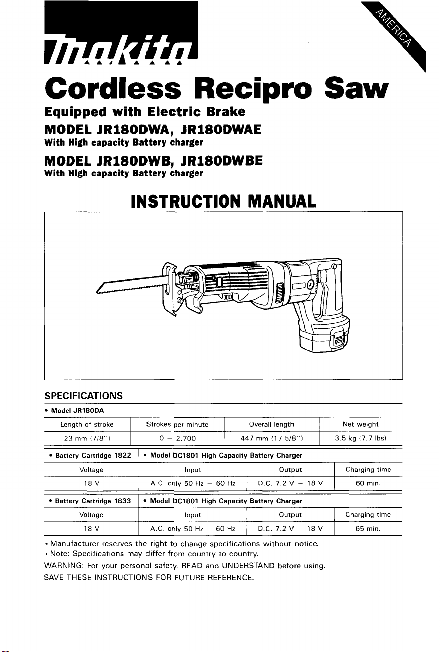
Cordless
Recipro
Equipped with Electric Brake
MODEL JR180DWA, JRl8ODWAE
With High capacity Battery charger
MODEL JR180DWB, JRl8ODWBE
With High capacity Battery charger
INSTRUCTION MANUAL
I
Saw
SPEC
I
FI
CAT1
0
N
S
Model JR180DA
Length
of
stroke
23
mm
(718")
Battery Cartridge 1822
Voltage
18 V
Battery Cartridge 1833 I Model DC1801 High Capacity Battery Charger
Voltage
18 V A.C.
Strokes per minute Overall length Net weight
447
mm
0
~ 2,700
Model DC1801 High Capacity Battery Charger
Input output Charging time
I
A.C.
only
50
Hz
-
60
Hz
I
Input
only
50 Hz ~ 60
Hz
(1
I
D.C.
I
D.C.
7-518")
7.2
V
output
7.2
V - 18
3.5 kg
(7.7
Ibs)
-
18
V
I
60
mtn
I
Charging time
V
65 min.
Page 2
GENERAL SAFETY RULES
(For
WARNING! Read and understand all instructions.
to follow
all
All
Battery Operated
Tools)
instructions listed below, may result
Failure
in
electric
shock, fire andlor serious personal injury.
SAVE
Work Area
*Keep your work area clean and well
accidents.
Do not operate power tools in explosive atmospheres, such as in the presence
of flammable liquids, gases, or dust. Power tools create sparks which may ignite
the dust or fumes.
Keep bystanders, children, and visitors away while operating a power tool.
Distractions can cause you to lose control.
Electrical Safety
A battery operated tool with integral batteries or a separate battery pack must
be recharged only
may be suitable for one type of battery may create a risk of fire when used with
another battery.
Use battery operated tool only with specifically designated battery pack. Use
of any other batteries may create a risk of fire.
Personal Safety
Stay alert, watch what you are doing, and use common sense when operating
a power tool. Do not use tool while tired or under the influence of drugs, alcohol,
or medication.
in serious personal injury.
Dress properly. Do not wear loose clothing or jewelry. Contain long hair. Keep
your hair, clothing, and gloves away from moving parts. Loose clothes, jewelry,
or long hair can be caught
Avoid accidental starting. Be sure switch is in the locked
inserting battery pack. Carrying tools with your finger on the switch or inserting
the battery pack into a tool
Remove adjusting keys
a key that is left attached to a rotating part of the
Do not overreach. Keep proper footing and balance at all times. Proper footing
and balance enable better control
Use safety equipment. Always wear eye protection. Dust mask, non-skid safety
shoes, hard hat, or hearing protection must be used for appropriate conditions.
THESE INSTRUCTIONS
lit.
Cluttered benches and dark areas invite
with
the specified charger for the battery. A charger that
A
moment of inattention while operating power tools may result
in
moving parts.
or
off position before
with
the switch on invites accidents.
or
wrenches before turning the tool on. A wrench or
tool
may result in personal injury.
of
the tool
in
unexpected situations.
2
Page 3
Tool
Use
and
Care
Use
clamps
stable platform. Holding the work by hand or against your body is unstable and
may lead to
*Do not force tool. Use the correct tool for your application. The correct tool
will
do the job better and safer at the rate for which
.Do not use tool if switch does not turn
controlled with the switch is dangerous and must be repaired.
Disconnect battery pack from tool or place the switch in the locked or off
position before making any adjustments, changing accessories,
tool. Such preventive safety measures reduce the risk of starting the tool
a cc id e n ta
Store idle tools out of reach of children and other untrained persons. Tools are
dangerous
When battery pack is not in use, keep
paper clips, coins, keys, nails, screws, or other small metal objects that can
make a connection from one terminal to another. Shorting the battery terminals
together may cause sparks, burns, or a fire.
Maintain tools with care. Keep cutting tools sharp and clean. Properly maintained
tools with sharp cutting edge are less likely to bind and are easier to control.
Check for misalignment or binding of moving parts, breakage of parts, and any
other condition that may affect the tool's operation.
serviced before using. Many accidents are caused by poorly maintained tools.
Use only accessories that are recommended
model. Accessories
when used on another tool.
or
other practical way
loss
of control.
I
I
y.
in
the hands of untrained users.
that
may be suitable for one tool may create a risk of injury
to
secure and support
it
on or off. A tool that cannot be
it
away from other metal objects like:
by
the manufacturer for your
the
workpiece
it
is designed.
If
damaged, have the tool
or
storing the
to
a
Service
Tool
service must be performed only by qualified repair personnel. Service or
in
maintenance performed by unqualified personnel may result
When servicing a tool, use only identical replacement parts. Follow instructions
in the Maintenance section of this manual, Use of unauthorized parts or failure
to follow Maintenance Instructions may create a risk of shock or injury.
a risk of injury.
3
Page 4
Specific Safety Rules
1.
Hold tool by insulated gripping surfaces when performing an operation where
the cutting tool may contact hidden wiring. Contact with a "live" wire
make exposed metal parts
2.
Be aware that this tool is always in an operating condition, because
not have to be plugged into an electrical outlet.
3.
Avoid cutting nails. Inspect workpiece for any nails and remove them before
operation.
4.
Do
not cut oversize workpiece.
5.
Check
the blade will not strike the floor, workbench, etc.
6.
Hold the tool firmly.
7.
Make sure the blade is not contacting the workpiece before the switch is
turned on.
8.
Keep hands away from moving parts.
9.
Always switch off and wait for the blade to come to a complete stop before
removing the blade from the workpiece.
IO.
Do
may be extremely hot and could burn your skin.
for
the proper clearance beyond the workpiece before cutting
not touch the blade or the workpiece immediately after operation; they
of
the tool "live" and shock the operator.
SAVE THESE INSTRUCTIONS.
it
so
will
does
that
4
Page 5
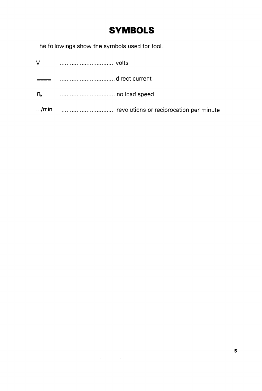
SYMBOLS
The followings show the
v
-
nl
...
/min
.................................
.................................
.................................
................................
symbols
used for tool.
volts
direct current
no
load speed
revolutions or reciprocation per minute
5
Page 6
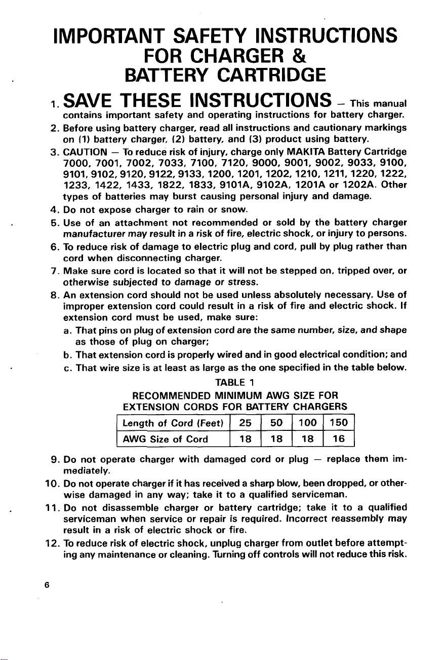
IMPORTANT SAFETY INSTRUCTIONS
FOR
BATTERY
1.
SAVE THESE INSTRUCTIONS
CHARGER
CARTRIDGE
&
-
This manual
Length of Cord (Feet)
AWG Size of Cord
6
25
18 18
50
100
18
150
16
Page 7

ADDITIONAL SAFETY RULES
FOR CHARGER
1.
Do
not charge Battery Cartridge when temperature is
ABOVE
or
2.
Do
not attempt to use a step-up transformer, an engine generator or DC power
receptacle.
3.
Do
not allow anything to cover or clog the charger vents.
4.
Always cover the battery terminals
cartridge is not used.
5.
A
battery short can cause a large current flow, overheating, possible burns
and even a breakdown.
(1
)
Do
(2)
Avoid storing battery cartridge
as nails, coins, etc.
(3)
Do
6.
Do
not store the tool and Battery Cartridge
ture may reach or exceed 5OoC
7.
Do
not incinerate the Battery Cartridge even if
completely worn out. The battery cartridge can explode
4OoC (104OF).
not touch the terminals
not expose battery cartridge to water or rain.
&
BATTERY CARTRIDGE
BELOW
with
the battery cover when the battery
with
any conductive material.
in
a container
(122OF).
with
other metal objects such
in
locations where the tempera-
it
is severely damaged or is
in
10°C
a fire.
(5OOF)
SAVE
THESE INSTRUCTIONS.
7
Page 8

FUNCTIONAL DESCRIPTION
Charging
Your new battery cartridge is not charged.
You
will
need to charge
the high capacity battery charger Model
DC1801 to charge the battery cartridge.
Plug the high capacity battery charger
into the proper A.C. voltage source. The
charging light will flash in green color.
*Insert the battery cartridge
plus and minus terminals on the battery
cartridge are on the same sides as their
respective markings on the high capacity
battery charger. Insert the cartridge fully
into the port
so
that it rests
When the battery cartridge is inserted, the charging light color
red and charging
When the charging light color changes from red
The charging time is approximately one hour.
If you leave the battery cartridge in the charger after the charging cycle is complete, the
charger will switch into its "trickle charge (maintenance charge)" mode which
approximately
24
After charging, unplug the charger from the power source.
CAUTION:
The high capacity battery charger Model DC1801 is for charging Makita battery cartridge.
it
Never use
for other purposes
When you charge a new battery cartridge or a battery cartridge which has not been used
for
a
long period of time, it may not accept a full charge. This is a normal condition and
does not indicate
ing it completely and recharging a couple of times.
If you charge a battery cartridge from a just-operated tool or a battery cartridge which
has been left in
a
light may flash in red color. If this occurs, wait for
battery cartridge cools. The battery cartridge will cool faster if you remove the battery
cartridge from the high capacity battery charger.
*If
the charging light flashes alternately in green and red color, a problem exists and charging is not possible. The terminals on the charger or battery cartridge are clogged with
dust or the battery cartridge is worn out or damaged.
it
before use. Use
so
that the
on
the charger port floor.
will
change from green to
will
begin. The charging light will remain
to
lit
steadily during charging.
green, the charging cycle is complete.
will
hours.
or
for other manufacturer's batteries.
a
problem. You can recharge the battery cartridge fully after discharg-
location exposed to direct sunlight or heat for a long time, the charging
a
while. Charging
will
begin after the
last
8
Page 9

Trickle charge (Maintenance charge)
If you leave the battery cartridge in the charger to prevent spontaneous discharging after
full charge, the charger will switch into its "trickle charge (maintenance charge)"
and keep the battery cartridge fresh and fully charged.
Tips for maintaining maximum battery life
1.
Charge the battery cartridge before completely discharged.
Always stop tool operation and charge the battery cartridge when you notice less tool
power
2.
Never recharge a fully charged battery cartridge.
Overcharging shortens the battery service life.
3.
Charge the battery cartridge with room temperature at
a
hot battery cartridge cool down before charging it.
Let
10°C
-
40°C (50°F - 104°F)
mode
Adjusting shoe
When the blade loses its cutting efficiency
in orle place along its cutting edge, reposition the shoe to unitize
tion of its cutting edge. This will help to
lengthen the life of the blade. To reposition
the shoe, loosen the lever and slide the
shoe forward or back to the desired position. Then tighten the lever to firmly secure
the shoe.
Switch action
CAUTION:
Before inserting the battery cartridge into the tool, always check to see that the switch
trigger actuates properly and returns to the "OFF" position when released.
To prevent the switch trigger from being accidentally pulled,
To start the tool, depress the lock-off button (from right side or left side) and ~ull the
switch trigger.
Tool
speed
is
increased by increasing pressure on the
switch trigger
switch trigger. Release the
.
to StOD.
a
sharp, unused por-
i
Lock-off
Shoe
a
button
Lever
I
Loosen
lock-off button is provided.
-1
9
Page 10

*Always switch off the tool before inser-
tion or removal of the battery cartridge.
*To remove the battery cartridge, with-
draw it from the tool while pressing the
buttons on both sides of the cartridge.
*To insert the battery cartridge, align the
tongue on the battery cartridge with the
groove in the housing and slip it until it is
locked with
Do
not use force when inserting the bat-
tery cartridge. If the cartridge does not
slide in easily, it is not being inserted correctly.
a
little click.
-
Battery
Installing or removing the saw blade
CAUTION:
*Always be sure that the
installing or removing the blade.
*Always clean out all chips or foreign matter adhering to the blade, blade clamp and/or
slider. Failure to do
ous injury.
To
install the blade, push the push button in the direction of the arrow and insert the blade
between the blade clamp and the slider as
and make sure that the blade cannot be extracted even though you
CAUTION:
If you release the push button without inserting the blade deep enough, the blade may be
ejected unexpectedly during operation. This can be extremely dangerous.
To
remove the blade, push the push button in the direction of the arrow and pull out the
blade.
tool
is switched off and the battery cartridge is removed before
so
may cause insufficient tightening of the blade, resulting in a seri-
far
as
it
will go. Then release the push button
try
to pull
it
out.
10
Blade
Push
button
c
0
Page 11

0
PE
RATIO
Press the shoe firmly against the workpiece.
Bring the blade into light contact with the
workpiece. First, make
a
slower speed. Then use a faster speed to
continue cutting.
If
the tool is operated continuously until the battery cartridge has discharged, allow the
tool to rest for
N
Do
not allow the tool to bounce.
a
pilot groove, using
15
minutes before proceeding with a fresh battery.
MAINTENANCE
CAUTION:
Always be sure that the tool is switched off and the battery cartridge is removed before
attempting to perform inspection
Replacing carbon brushes
Remove and check the carbon brushes
regularly. Replace when they wear down to
the limit mark. Keep the carbon brushes
clean and free to slip in the holders. Both
carbon brushes should be replaced at the
same time. Use only identical carbon
brushes.
or
maintenance.
/
Limit mark
Use
a
holder caps. Take out the worn carbon
brushes, insert the new ones and secure
the brush holder caps.
To
ment should be performed by Makita Authorized or Factory Service Centers, always using
Makita replacement parts.
screwdriver to remove the brush
maintain product SAFETY and RELIABILITY, repairs, any other maintenance or adjust-
Brush holder cap Screwdriver
11
Page 12

Recycling the Battery
The
only
way
to
dispose
to
recycle it. The law prohibits any other
of
method
To recycle the battery:
1.
Remove the battery from the tool.
2.
a). Take the battery to your nearest Makita Factory Service Center
or
b). Take the battery to your nearest Makita Authorized Service Center or
Distributor that has been designated as a Makita battery recycling location.
Call your nearest Makita Service Center or Distributor to determine the location
that provides Makita battery recycling. See your local Yellow Pages under
’
’
Tools-Electric
ACCESSORIES
CAUTION
These accessories or attachments are recommended
manual The use
These accessories
of
disposal.
’
:
any other accessories
or
attachments should
of
a Makita battery is
for
or
attachments might present a risk
be
used only in the proper and intended manner
use with your Makita tool specified in this
p-
Ni-Cd
of
injury to persons
-
High capacity battery charger
Model DC1801
Battery cover
Part No. 414938-7
12
Battery cartridge 1822
Part No. 192827-3
Battery cartridge 1833
Part No. 192829-9
Page 13
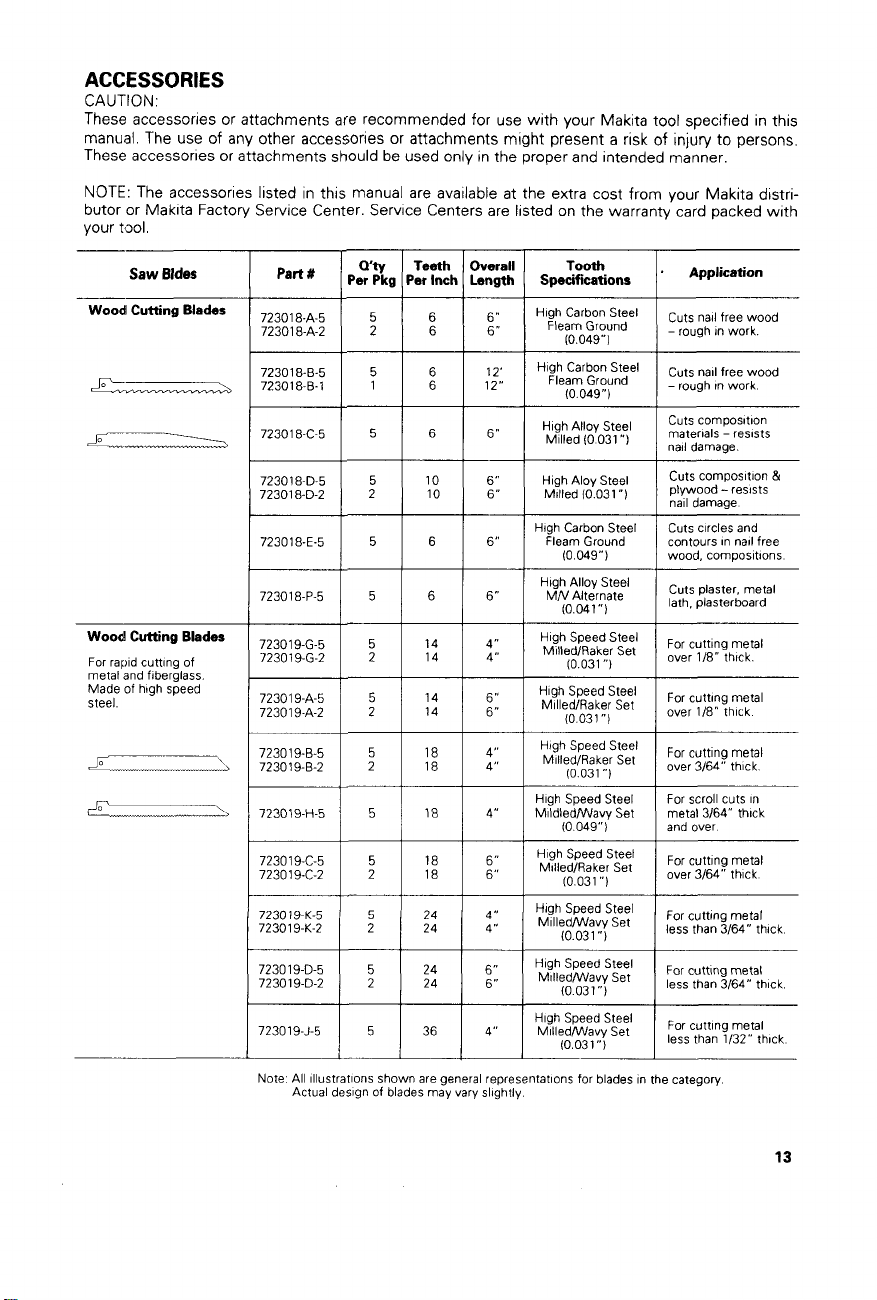
ACCESSORIES
CA
UTI
0
N
These accessories or attachments are recommended
manual The use of any other acces~ories or attachments might present a risk of injury to persons
These accessories or attachments should be used only
NOTE
The accessories listed in this manual are available at the extra cost from your Makita distributor or Makita Factory Service Center Service Centers are listed on the warranty card packed with
your t3oI
Wty
'
Per Pkg Per Inch
1
Wood
Saw
Bldes
Cutting Blades
part
723018-A-5
723018-A-2
1 E I
723018-6-5 High
723018-6-1
1
7
I
for
use
in
the proper and intended manner
Teeth
Overall
Length Specifications
El
I
:$
with
your Makita tool specified in this
High
I
Tooth
Carbon
Fleam
(0
Carbon
Fleam
(0
Ground
049")
Ground
049")
Steel
Steel
.
Application
Cuts nail free wood
-rough in work
Cuts nail free wood
1
-rough tnwork
Wood
Cutting Blades
For rapid cutting of
metal and fiberglass
Made of high speed
steel
High Carbon Steel
Fleam Ground
(0
049")
5
5
14
2 14
1:
18
5
18
5
18
24
24
24
36
6
1
I
I
723018-P-5
723019-G-5
723019-G-2
72301 9-A-5
723019-A-2
723019-H-5
723019-C-5
723019-C-2
7230
72301 9-K-2
723019-D-5
723019-D-2
723019-J-5
Note All illustrations shown are general representations for blades in the category
I ! 1
I 2 I
19
K-5
5
2 24
5
2
1 5 1
Actual design of blades may vary slightly
H~~~I~~rnsaff~l
6"
:l
:"
4" MildledNavy Set metal 3/64" thick
6"
6"
4"
4" Milled/Wavy
6"
6"
4"
(0
041")
High
Speed
MilledlRaker Set
(0
031
"1
High
Speed
1
Mi"7~/~~~e;set
High Speed Steel
(0
049") and over
High
Speed
Speed
(0031")
Speed
(0
031")
Speed
(0
031")
Steel
Steel
Steel
I
Mi"7~'~~~e;
High
High
Mil1edNavy
High
I
MilledNavy
Steel
Steel
Set
Set
Set
Set
Cuts circles and
contours in nail free
wood, compositions
Cuts piaster. metal
lath, plasterboard
For cutting metal
Over
1/8,.
For cutting metal
1
over 1/8" thick
For scroll cuts in
For cutting metal
1
over3/64" thick
For cutttng metal
less than 3/64" thick
For cuttlng metal
less
than 3/64" thick
For cutting metal
less than 1/32" thick
13
Page 14

ACCESSORIES
Bi-metal
Blades
Combination
speed steel teeth
welded to
proof, flexible backed
blade Ultra-long life
blade
of
a
shatter-
high
continued
-
3
Piece Variety Pack
Wood and Metal Cutting
includes 1 each: 723018-A
This pack is available under
Part
No.
723016-3-A
-
Plastic
Tool
Part
No.
824037-1
Accommodated tool with
14
72301 8-D
72301 9-C
Case
6"
blade.
3
Piece Variety Pack
Ultra Long Life 81-metal
includes 1 each: 723017-E
This pack is available under
Part
No.
723016-3-8
72301 7-8
72301 7-C
Page 15

MAKrA
LIMrrED
ONE
YEAR
WARRANTY
Warranty
Every Makita tool is thoroughly inspected and tested before leaving the factory.
be free of defects from workmanship and materials for the period of ONE YEAR from the date of
original purchase. Should any trouble develop during this one-year period, return the COMPLETE
tool,
freight prepaid,
the trouble is caused by defective workmanship or material, Makita
replace) without charge.
This Warranty does not apply where:
repairs have been made or attempted by others:
repairs are required because of normal wear and tear:
The
tool
alterations have been made
IN NO EVENT SHALL MAKlTA BE LIABLE FOR ANY INDIRECT, INCIDENTAL OR CONSEQUENTIAL DAMAGES FROM THE SALE
APPLIES BOTH DURING AND AFTER THE TERM
MAKlTA DISCLAIMS LIABILITY FOR ANY IMPLIED WARRANTIES, INCLUDING IMPLIED
WARRANTIES OF “MERCHANTABILITY” AND “FITNESS FOR A SPECIFIC PURPOSE.”
AFTER THE ONE-YEAR TERM
This Warranty gives you specific legal rights, and you may also have other rights which vary from
state to state. Some states do not allow the exclusion or limitation of incidental or consequential
so
damages,
limitation on how long an implied warranty lasts,
to
one of Makita’s Factory or Authorized Service Centers. If inspection shows
has been abused, misused or improperly maintained;
the above limitation or exclusion may not apply
to
the
tool.
OF
THIS WARRANTY.
Policy
will
repair (or at our option,
OR
USE
OF
THE PRODUCT. THIS DISCLAIMER
OF
THIS WARRANTY.
to
so
the above Limitation may not apply
you. Some states do not allow
It
is warranted
to
to
you.
Makita Corporation
2650
Buford
Hwy.,
Buford,
884245
-
GA
068
of
America
30518
PRINTED
IN
USA
 Loading...