

Page 1
GB Resipro Saw Instruction manual
F Scie recipro Manuel d’instructions
D Reciprosäge Betriebsanleitung
I Seghetto diritto Istruzioni per l’uso
NL Reciprozaag Gebruiksaanwijzing
E Sierra de sable Manual de instrucciones
P Serra de sabre Manual de instruções
DK Bajonet sav Brugsanvisning
S Rak sticksåg Bruksanvisning
N Bajonettsag Bruksanvisning
SF Puukkosaha Käyttöohje
GR Παλινδροµικ πρινι Οδηγίες χρήσης
JR3060T
JR3070CT
Page 2
A
1
2
B
21
12
3
4
5
6
34
7
9
8
10
56
11
12
78
2
Page 3
13
910
14
15
11
Symbols
The following show the symbols used for the tool. Be sure that you understand their meaning before use.
Symboles
Nous donnons ci-dessous les symboles utilisés pour l’outil. Assurez-vous que vous en avez bien compris la signification
avant d’utiliser l’outil.
Symbole
Die folgenden Symbole werden für die Maschine verwendet. Machen Sie sich vor der Benutzung unbedingt mit ihrer
Bedeutung vertraut.
Symboli
Per questo utensile vengono usati i simboli seguenti. Bisogna capire il loro significato prima di usare l’utensile.
Symbolen
Voor dit gereedschap worden de volgende symbolen gebruikt. Zorg ervoor dat u de betekenis van deze symbolen
begrijpt alvorens het gereedschap te gebruiken.
Símbolos
A continuación se muestran los símbolos utilizados con esta herramienta. Asegúrese de que entiende su significado
antes de usarla.
Símbolos
O seguinte mostra os símbolos utilizados para a ferramenta. Certifique-se de que compreende o seu significado antes
da utilização.
Symboler
Nedenstående symboler er anvendt i forbindelse med denne maskine. Vær sikker på, at De har forstået symbolernes
betydning, før maskinen anvendes.
Symboler
Det följande visar de symboler som används för den här maskinen. Se noga till att du förstår deras innebörd innan
maskinen används.
Symbolene
Følgende viser de symblene som brukes for maskinen. Det er viktig å forstå betydningen av disse før maskinen tas i
bruk.
3
Page 4

Symbolit
Alla on esitetty koneessa käytetyt symbolit. Opettele näiden merkitys, ennen kuin käytät konetta.
Σύµβολα
Τα ακλουθα δείχνουν τα σύµβολα που χρησιµοποιούνται για το µηχάνηµα. Βεβαιωθείτε τι καταλαβαίνετε τη
σηµασία τους πριν απ τη χρήση.
❏ Read instruction manual. ❏ Leia o manual de instruções.
❏ Lire le mode d’emploi. ❏ Læs brugsanvisningen.
❏ Bitte Betriebsanleitung lesen. ❏ Läs bruksanvisningen.
❏ Leggete il manuale di istruzioni. ❏ Les bruksanvisingen.
❏ Lees de gebruiksaanwijzing. ❏ Katso käyttöohjeita.
❏ Lea el manual de instrucciones. ❏ ∆ιαβάστε τις οδηγίες χρήσης.
❏ DOUBLE INSULATION ❏ DUPLO ISOLAMENTO
❏ DOUBLE ISOLATION ❏ DOBBELT ISOLERET
❏ DOPPELT SCHUTZISOLIERT ❏ DUBBEL ISOLERING
❏ DOPPIO ISOLAMENTO ❏ DOBBEL ISOLERING
❏ DUBBELE ISOLATIE ❏ KAKSINKERTAINEN ERIST
❏ DOBLE AISLAMIENTO ❏ ∆ΙΠΛΗ ΜΟΝΩΣΗ
4
Page 5
ENGLISH
1Shoe
2 Shoe button
3 Lever
4 Stopper
5 Switch trigger
Explanation of general view
6 Lock button
7 Adjusting dial
8 Blade clamp lever
9 Released position
10 Fixed position
11 Bl ade
12 Blade clamp lever
13 Limit mark
14 Brush holder cap
15 Screwdriver
SPECIFICATIONS
Model JR3060T/JR3070CT
Length of stroke...................................................... 32 mm
Max. cutting capacities
Pipe ............................................................... 130 mm
Wood ............................................................. 255 mm
Strokes per minute (min
Overall length............................................................... 485
Net weight.............................................. 4.2 kg (JR3060T)
......................................................4.4 kg (JR3070CT)
Safety class ................................................................ /II
• Due to our continuing program of research and development, the specifications herein are subject to change
without notice.
• Note: Specifications may differ from country to country.
Intended use
The tool is intended for sawing wood, plastic, metal and
building materials with a strong impact. It is suitable for
straight and curved cutting.
Power supply
The tool should be connected only to a power supply of
the same voltage as indicated on the nameplate, and can
only be operated on single-phase AC supply. They are
double-insulated in accordance with European Standard
and can, therefore, also be used from sockets without
earth wire.
-1
) ................................... 0 - 2,800
ADDITIONAL SAFETY RULES
FOR TOOL
GEB008-1
DO NOT let comfort or familiarity with product (gained
from repeated use) replace strict adherence to recipro
saw safety rules. If you use this tool unsafely or incorrectly, you can suffer serious personal injury.
1. Hold power tool by insulated gripping surfaces
when performing an operation where the cutting
tool may contact hidden wiring or its own cord.
Contact with a “live” wire will make exposed metal
parts of the tool “live” and shock the operator.
2. Use clamps or another practical way to secure and
support the workpiece to a stable platform. Holding
the work by hand or against your body leaves it unstable and may lead to loss of control.
3. Always use safety glasses or goggles. Ordinary
eye or sun glasses are NOT safety glasses.
4. Avoid cutting nails. Inspect workpiece for any
nails and remove them before operation.
5. Do not cut oversize workpiece.
6. Check for the proper clearance beyond the workpiece before cutting so that the blade will not
strike the floor, workbench, etc.
7. Hold the tool firmly.
8. Make sure the blade is not contacting the workpiece before the switch is turned on.
9. Keep hands away from moving parts.
10. Do not leave the tool running. Operate the tool
only when hand-held.
11. Always switch off and wait for the blade to come
to a complete stop before removing the blade from
the workpiece.
12. Do not touch the blade or the workpiece immediately after operation; they may be extremely hot
and could burn your skin.
13. Do not operate the tool at no-load unnecessarily.
14. Always use the correct dust mask/respirator for
the material and application you are working with.
15. Some material contains chemicals which may be
toxic. Take caution to prevent dust inhalation and
skin contact. Follow material supplier safety data.
5
Page 6
SAVE THESE INSTRUCTIONS.
WARNING:
MISUSE or failure to follow the safety rules stated in
this instruction manual may cause serious personal
injury.
FUNCTIONAL DESCRIPTION
CAUTION:
• Always be sure that the tool is switched off and
unplugged before adjusting or checking function on the
tool.
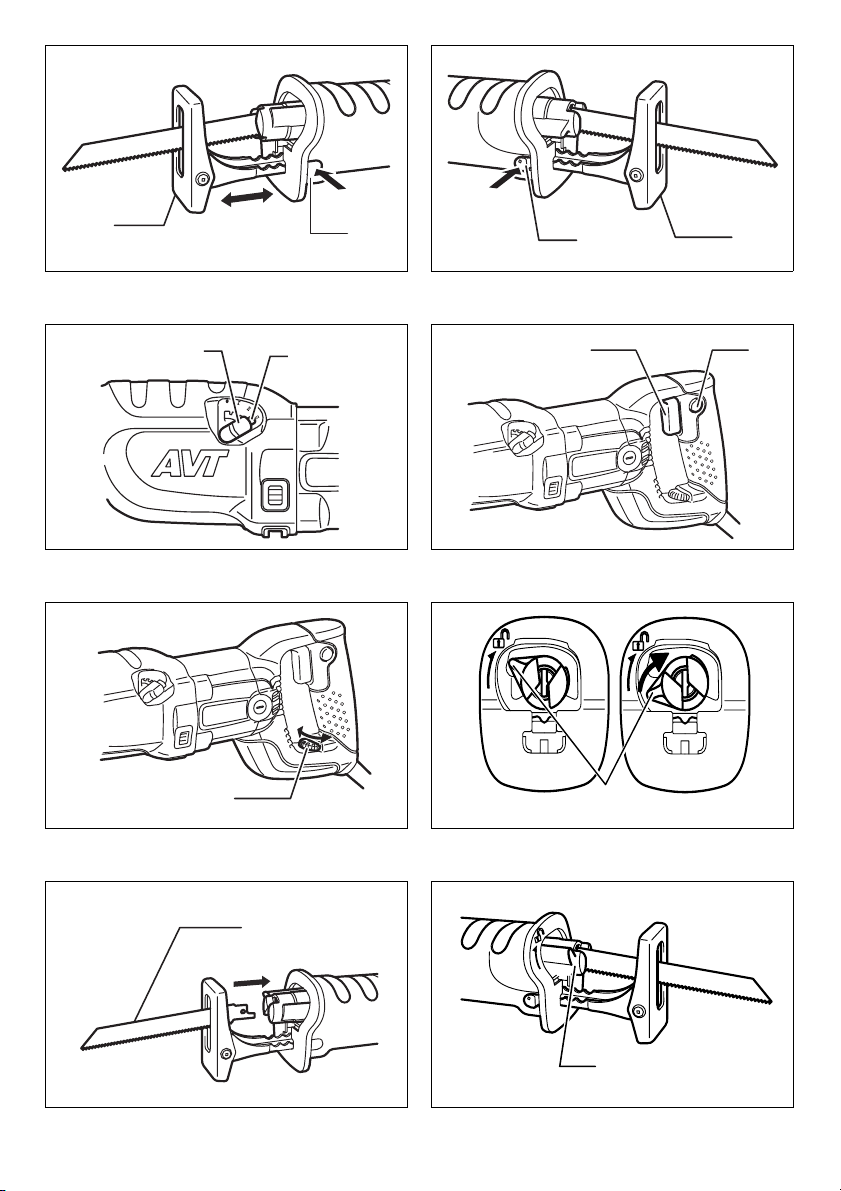
Adjusting the shoe (Fig. 1 & 2)
When the blade loses its cutting efficiency in one place
along its cutting edge, reposition the shoe to utilize a
sharp, unused portion of its cutting edge. This will help to
lengthen the life of the blade. To reposition the shoe, push
the shoe button in the “A” direction with a click and reposition as shown in the figure which allows you to make fiveway adjustment. To secure the shoe, push the shoe button in the “B” direction with a click.
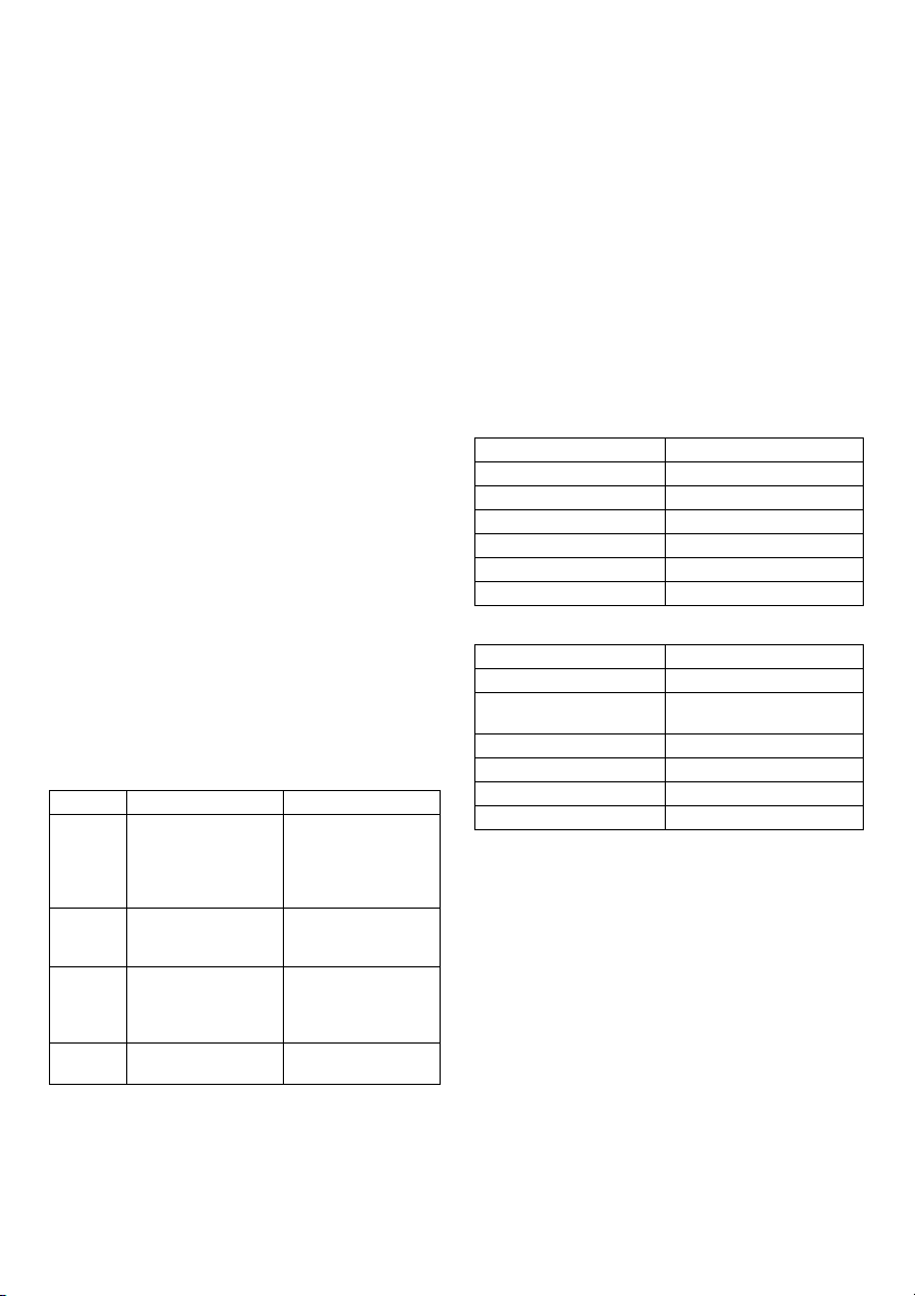
Selecting the cutting action (Fig. 3)
This tool can be operated with an orbital or a straight line
cutting action. The orbital cutting action thrusts the blade
forward on the cutting stroke and greatly increases cutting
speed.
To change the cutting action, press the stopper and turn
the lever to the desired cutting action position. Then,
release the stopper to lock the lever. Refer to the table to
select the appropriate cutting action.
Note:
Orbital action means that the saw blade moves up and
down, and back and forth at the same time. This
increases the efficiency of cutting.
Position Cutting action Applications
0 Straight line cutting
I Small orbit cutting
II Medium orbit cutting
III Large orbit cutting
action
action
action
action
Switch action (Fig. 4 & 5)
CAUTION:
• Before plugging in the tool, always check to see that
the switch trigger actuates properly and returns to the
“OFF” position when released.
For cutting mild steel,
stainless steel and
plastics.
For clean cuts in
wood and plywood.
For cutting mild steel,
aluminum and hard
wood.
For cutting wood and
plywood.
For fast cutting in aluminum and mild steel
For fast cutting in
wood and plywood.
To start the tool, simply pull the switch trigger. Tool speed
is increased by increasing pressure on the switch trigger.
Release the switch trigger to stop. For continuous operation, pull the switch trigger and then push in the lock button.
To stop the tool from the locked position, pull the switch
trigger fully, then release it.
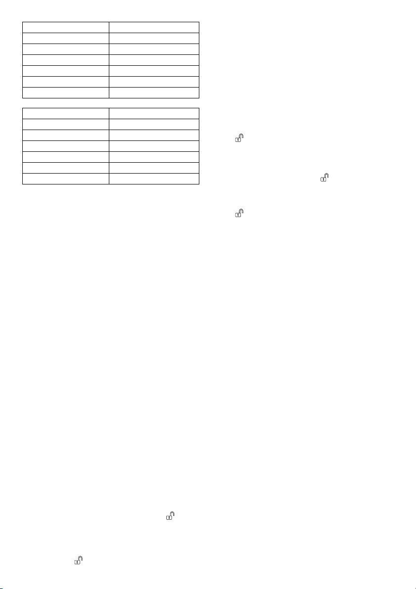
Speed adjusting dial (For JR3070CT)
The strokes per minute can be adjusted just by turning the
adjusting dial. This can be done even while the tool is running. The dial is marked 1 (lowest speed) to 6 (full speed).
Turn the adjusting dial without positive stops between 1
and 6 according to your work.
Refer to the table to select the proper speed for the workpiece to be cut. However, the appropriate speed may differ with the type or thickness of the workpiece. In general,
higher speeds will allow you to cut workpieces faster but
the service life of the blade will be reduced.
Number on adjusting dial Strokes per minute
6 2,800
5 2,500
4 1,850
3 1,400
2 1,000
1950
Workpiece to be cut Number on adjusting dial
Wood 6
Autoclaved lightweight
concrete
Mild steel 3 - 4
Aluminum 3 - 5
Plastics 1 - 4
Stainless steel 1 - 2
CAUTION:
• If the tool is operated continuously at low speeds for a
long time, the motor will get overloaded and heated up.
• The speed adjusting dial can be turned only as far as 6
and back to 1. Do not force it past 6 or 1, or the speed
adjusting function may no longer work.
The tools equipped with electronic function are easy to
operate because of the following features.
Constant speed control
Electronic speed control for obtaining constant speed.
Possible to get fine finish, because the rotating speed is
kept constant even under load condition.
Soft start feature
Safety and soft start because of suppressed starting
shock.
5 - 6
6
Page 7

ASSEMBLY
CAUTION:
• Always be sure that the tool is switched off and
unplugged before carrying out any work on the tool.
Installing or removing saw blade
CAUTION:
• Always clean out all chips or foreign matter adhering to
the blade, blade clamp and/or slider. Failure to do so
may cause insufficient tightening of the blade, resulting
in a serious injury.
To install the saw blade, always make sure that the blade
clamp lever is in released position on the insulation
cover before inserting the saw blade. If the blade clamp
lever is in fixed position, rotate the blade clamp lever in
the direction of the arrow so that it can be locked at the
released position . (Fig. 6)
Insert the saw blade into the blade clamp as far as it will
go. The blade clamp sleeve rotates and the saw blade is
fixed. Make sure that the saw blade cannot be extracted
even though you try to pull it out. (Fig. 7)
NOTE:
• If you do not insert the saw blade deep enough, the
saw blade may be ejected unexpectedly during operation. This can be extremely dangerous.
To remove the saw blade, rotate the blade clamp lever in
the direction of the arrow fully. The saw blade is removed
and the blade clamp lever is fixed at the released position
. (Fig. 8)
NOTE:
• If you remove the saw blade without rotating the blade
clamp lever fully, the lever may not be locked in the
released position . In this case, rotate the blade
clamp lever fully again, then make sure that the blade
clamp lever locked at the released position .
MAITENANCE
CAUTION:
• Always be sure that the tool is switched off and
unplugged before attempting to perform inspection or
maintenance.
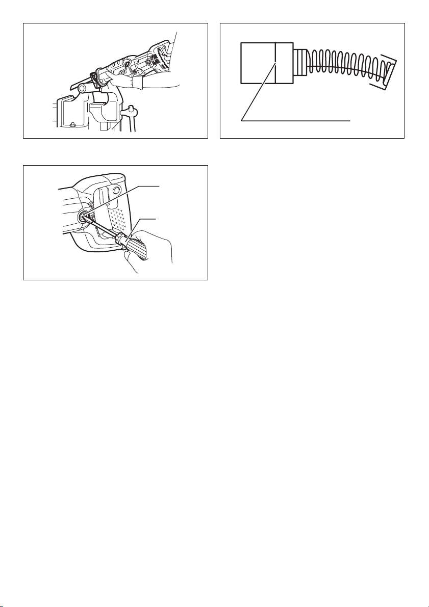
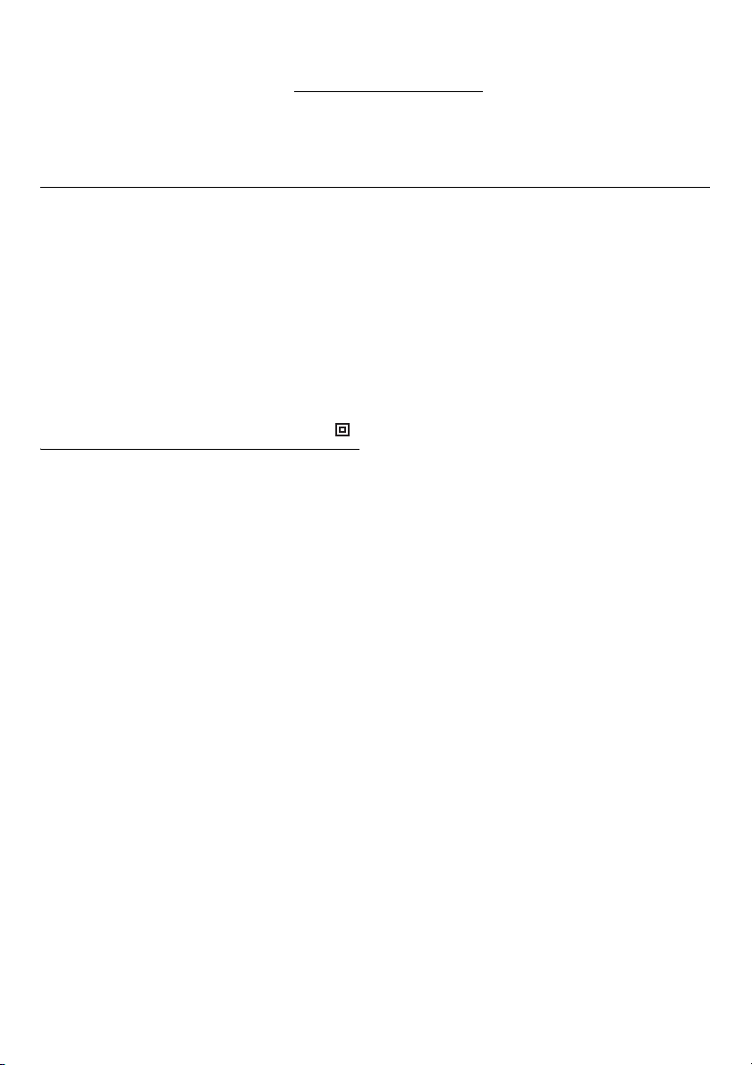
Replacing carbon brushes (Fig. 10 & 11)
Remove and check the carbon brushes regularly. Replace
when they wear down to the limit mark. Keep the carbon
brushes clean and free to slip in the holders. Both carbon
brushes should be replaced at the same time. Use only
identical carbon brushes.
Use a screwdriver to remove the brush holder caps. Take
out the worn carbon brushes, insert the new ones and
secure the brush holder caps.
To maintain product SAFETY and RELIABILITY, repairs,
any other maintenance or adjustment should be performed by Makita Authorized Service Centers, always
using Makita replacement parts.
ACCESSORIES
CAUTION:
• These accessories or attachments are recommended
for use with your Makita tool specified in this manual.
The use of any other accessories or attachments might
present a risk of injury to persons. Only use accessory
or attachment for its stated purpose.
If you need any assistance for more details regarding
these accessories, ask your local Makita service center.
• Recipro saw blade
• Plastic carrying case
OPERATION (FIG. 9)
CAUTION:
• Always press the shoe firmly against the workpiece
during operation. If the shoe is held away from the
workpiece during operation, strong vibration and/or
twisting will be produced, causing the blade to snap
dangerously.
• Always wear gloves to protect your hands from hot flying chips when cutting metal.
• Be sure to always wear suitable eye protection which
conforms with current national standards.
• Always use a suitable coolant (cutting oil) when cutting
metal. Failure to do so will cause premature blade
wear.
Press the shoe firmly against the workpiece. Do not allow
the tool to bounce. Bring the blade into light contact with
the workpiece. First, make a pilot groove, using a slower
speed. Then use a faster speed to continue cutting.
7
Page 8

NEDERLANDS
1 Schoen
2 Schoenknop
3Instelknop
4 Vergrendelknopje
5 Trekschakelaar
Verklaring van algemene gegevens
6 Vergrendelknop
7 Instelwiel
8 Zaagbladklemhendel
9 Vrije stand
10 Vaste stand
11 Zaagblad
12 Zaagbladklemhendel
13 Limietmarkering
14 Koolborsteldop
15 Schroevendraaier
TECHNISCHE GEGEVENS
Model JR3060T/JR3070CT
Slaglengte............................................................... 32 mm
Max. zaagcapaciteiten
Pijp.................................................................130 mm
Hout...............................................................255 mm
Aantal zaagbewegingen/min (min
Totale lengte ................................................................ 485
Netto gewicht ......................................... 4,2 kg (JR3060T)
......................................................4,4 kg (JR3070CT)
Veiligheidsklasse ........................................................ /II
• In verband met ononderbroken research en
ontwikkeling behouden wij ons het recht voor
bovenstaande technische gegevens te wijzigen zonder
voorafgaande kennisgeving.
• Opmerking: De technische gegevens kunnen van land
tot land verschillen.
Doeleinden van gebruik
Dit gereedschap is bedoeld voor het zagen van hout,
kunststof, metaal en bouwmaterialen met grote
slagsterkte. Het is geschikt voor zowel recht als krom
zagen.
Stroomvoorziening
Het gereedschap mag alleen worden aangesloten op een
stroombron van hetzelfde voltage als aangegeven op de
naamplaat, en kan alleen op enkel-fase wisselstroom
worden gebruikt. Het gereedschap is dubbel-geïsoleerd
volgens de Europese standaard en kan derhalve ook op
een niet-geaard stopcontact worden aangesloten.
-1
).................... 0 - 2.800
AANVULLENDE
VEILIGHEIDSVOORSCHRIFTEN
VOOR DE MACHINE
Laat u NIET misleiden door een vals gevoel van
gemak of vertrouwdheid met het gereedschap
(verworven na langdurig gebruik) en neem alle
veiligheidsvoorschriften voor de reciprozaag altijd
strict in acht. Bij onveilig of verkeerd gebruik van het
gereedschap bestaat er gevaar voor zware
verwondingen.
1. Houd elektrisch gereedschap vast bij de
geïsoleerde handgreepoppervlakken wanneer u
GEB008-1
werkt op plaatsen waar het snijgereedschap met
verborgen bedrading of zijn eigen stroomkabel in
aanraking kan komen. Door contact met onder
spanning staande draden zullen de nietgeïsoleerde metalen delen van het gereedschap
onder spanning komen te staan zodat de
gebruiker een elektrische schok kan krijgen.
2. Gebruik klemmen of andere bevestigingsmiddelen
om het werkstuk op een stabiel platform te
bevestigen en te ondersteunen. Het werkstuk is
onstabiel en er is gevaar voor controleverlies
wanneer u het werkstuk met de hand vasthoudt of
het tegen uw lichaam houdt.
3. Draag altijd een veiligheidsbril of een
beschermbril. Een gewone bril of een zonnebril is
GEEN veiligheidsbril.
4. Vermijd het zagen op spijkers. Inspecteer het
werkstuk alvorens met het zagen te beginnen en
haal alle spijkers eruit.
5. Zaag geen werkstukken die te groot zijn.
6. Controleer vooraf of er voldoende ruimte voorbij
het werkstuk is, zodat het zaagblad niet tegen de
vloer, een werkbank e.d. zal stoten.
7. Houd het gereedschap stevig vast.
8. Zorg dat het zaagblad het werkstuk niet raakt
voordat u de trekschakelaar indrukt.
9. Houd uw handen uit de buurt van bewegende
delen.
10. Laat het gereedschap niet achter terwijl het nog in
bedrijf is. Laat het gereedschap alleen draaien
wanneer u het met de handen vasthoudt.
11. Schakel het gereedschap uit en wacht totdat het
zaagblad volledig tot stilstand is gekomen
alvorens het zaagblad van het werkstuk te
verwijderen.
12. Raak het zaagblad of het werkstuk niet aan
onmiddellijk na het werk; deze kunnen gloeiend
heet zijn en brandwonden veroorzaken.
13. Laat het gereedschap niet onbelast draaien
wanneer zulks niet nodig is.
14. Draag altijd het stofmasker/gasmasker dat
geschikt is voor het materiaal en de toepassing
waarmee u werkt.
15. Sommige materialen bevatten chemische stoffen
die vergiftig kunnen zijn. Vermijd inademing van
stof en contact met de huid. Volg de
veiligheidsinstructies van de leverancier van het
materiaal.
20
Page 9

BEWAAR DEZE
VOORSCHRIFTEN.
WAARSCHUWING:
VERKEERD GEBRUIK of het niet naleven van de
veiligheidsvoorschriften in deze gebruiksaanwijzing
kan leiden tot ernstige verwondingen.
BESCHRIJVING VAN DE FUNCTIES
LET OP:
• Controleer altijd of het gereedschap is uitgeschakeld
en zijn stekker uit het stopcontact is verwijderd
alvorens de functies op het gereedschap te controleren
of af te stellen.
Bijstellen van de schoen (Fig. 1 en 2)
Wanneer een gedeelte van de snede van het zaagblad
niet meer goed snijdt, dient u de positie van de schoen bij
te stellen om een ongebruikt scherp gedeelte van de
snede te gebruiken. Het zaagblad zal dan langer
meegaan. Om de schoen bij te stellen, druk de
schoenknop in de richting “A” tot u een klikgeluid hoort en
stel af op een van de vijf beschikbare posities zoals
afgebeeld. Zet de schoen weer vast door de schoenknop
in de richting “B” te drukken tot u een klikgeluid hoort.
De zaagmethode kiezen (Fig. 3)
Dit gereedschap kan worden gebruikt met een
pendelende of rechte zaagmethode. In de pendelende
zaagmethode wordt het zaagblad tijdens de zaagslag
krachtig naar voren geduwd, waardoor de zaagsnelheid
sterk toeneemt.
Als u de zaagmethode wilt veranderen, drukt u het
vergrendelknopje in en zet u de instelknop in de gewenste
zaagmethodestand. Laat daarna het vergrendelknopje los
om de instelknop te vergrendelen. Raadpleeg de
onderstaande tabel om de toepasselijke zaagmethode te
bepalen.
OPMERKING:
Orbital action means that the saw blade moves up and
down, and back and forth at the same time. This
increases the efficiency of cutting.
Stand Zaagmethode Toepassing
0 Zagen in een rechte
I Zagen met geringe
II Zagen met
III Zagen met sterke
lijn
pendelbeweging
gemiddelde
pendelbeweging
pendelbeweging
Voor zagen van
zachtstaal,
roestvrijstaal en
kunststof.
Voor schone
zaagsnede in hout,
multiplex, enz.
Voor zagen van
zachtstaal, aluminium
en hardhout.
Voor zagen van hout,
multiplex, enz.
Voor snel zaken van
aluminium en
zachtstaal
Voor snel zagen van
hout, multiplex, enz.
Werking van de trekkerschakelaar (Fig. 4
en 5)
LET OP:
• Alvorens de stekker in een stopkontakt te steken, dient u
altijd te kontroleren of de trekkerschakelaar naar behoren
werkt en bij loslaten naar de “OFF” positie terugkeert.
Om het gereedschap te starten, drukt u gewoon de
trekkerschakelaar in. Hoe groter de druk op de
trekkerschakelaar, hoe sneller het gereedschap draait.
Laat de trekkerschakelaar los om het gereedschap te
stoppen.
Voor continu zagen drukt u de trekkerschakelaar in en
dan drukt u de vergrendelknop in.
Om het gereedschap vanuit deze vergrendelde stand te
stoppen, drukt u de trekkerschakelaar volledig in en dan
laat u hem los.
Snelheidsinstelwiel (voor JR3070CT)
Het aantal slagen per minuut kan worden ingesteld door
eenvoudigweg het instelwiel te draaien. Dit kan zelfs
worden gedaan terwijl het gereedschap is ingeschakeld.
Op het instelwiel wordt de minimumsnelheid aangegeven
met 1 en de maximumsnelheid met 6. U kunt het
instelwiel traploos draaien tussen 1 en 6 al naar gelang
uw werk vereist.
Raadpleeg de tabel om de juiste snelheid te kiezen voor
het werkstuk dat moet worden gezaagd. De toepasselijke
snelheid kan echter verschillen afhankelijk van het soort
en de dikte van het werkstuk. Over het algemeen geldt
dat met een hogere snelheid een werkstuk sneller
gezaagd kan worden, maar dat de levensduur van de
zaag afneemt.
21
Page 10
Nummer op instelwiel Slagen per minuut
6 2.800
5 2.500
4 1.850
3 1.400
2 1.000
1950
Te zagen werkstuk Getal op instelknop
Hout 6
Lichte beton uit autoclaaf 5 - 6
Zacht staal 3 - 4
Aluminium 3 - 5
Kunststof 1 - 4
Roestvrij staal 1 - 2
LET OP:
• Als het gereedschap gedurende een lange tijd continu
op lage snelheid wordt gebruikt, zal de motor
overbelast worden en oververhit raken.
• De snelheidsregelknop kan slechts van 1 tot 6 gedraaid
worden. Forceer deze niet voorbij 6 of 1 omdat anders
de snelheidsregelfunctie kapot kan gaan.
Gereedschappen uitgerust met een elektronische functie
zijn eenvoudig te bedienen vanwege de volgende
eigenschappen:
Constante snelheidsregeling
Elektronische snelheidsregeling zorgt voor een constante
snelheid. U krijgt een gave afwerking omdat de
draaisnelheid constant wordt gehouden, zelfs onder
belasting.
Geleidelijke-startfunctie
Veilig en geleidelijk starten doordat de startschok wordt
onderdrukt.
INEENZETTEN
LET OP:
• Zorg altijd dat het gereedschap is uitgeschakeld en zijn
stekker uit het stopcontact is verwijderd alvorens enig
werk aan het gereedschap uit te voeren.
Steek het zaagblad zo ver mogelijk in de zaagbladklem.
De zaagbladklembus roteert en het zaagblad wordt
vastgezet. Controleer of het zaagblad niet eruit komt
wanneer u eraan trekt. (Fig. 7)
OPMERKING:
• Als het zaagblad niet diep genoeg erin zit, kan het
zaagblad tijdens het zagen onverwachts eruit
geworpen worden, hetgeen bijzonder gevaarlijk is.
Om het zaagblad te verwijderen, draait u de
zaagbladklemhendel zo ver mogelijk in de richting van de
pijl. Het zaagblad wordt verwijderd en de
zaagbladklemhendel wordt vergrendeld in de geopende
stand . (Fig. 8)
OPMERKING:
• Als u het zaagblad verwijdert, zonder eerst de
zaagbladklemhendel zo ver mogelijk te draaien, kan de
hendel niet in de geopende stand vergrendeld
worden. In dat geval draait u nogmaals de
zaagbladklemhendel zo ver mogelijk en controleert u dat
de zaagbladklemhendel is vergrendeld in de geopende
stand .
BEDIENING (FIG. 9)
LET OP:
• Druk tijdens het zagen de schoen altijd flink tegen het
werkstuk aan. Als u tijdens het zagen de schoen van
het werkstuk afneemt, zullen sterke vibraties en/of
kromtrekken van het zaagblad het gevolg zijn. Het
zaagblad kan dan breken hetgeen zeer gevaarlijk is.
• Trek voor zagen in metaal altijd handschoenen aan om
uw handen te beschermen tegen wegvliegende hete
metaaldeeltjes.
• Draag altijd geschikte oogbescherming die voldoet aan
de geldende plaatselijke normen.
• Gebruik voor zagen in metaal altijd een geschikt
koelmiddel (snijolie). Laat u dit na dan zal de
gebruiksduur van het zaagblad voortijdig worden
verkort.
Druk de schoen flink tegen het werkstuk aan. Zorg ervoor
dat het gereedschap geen schokken maakt. Breng
vervolgens het zaagblad in contact met het werkstuk.
Maar eerst met lage zaagsnelheid een geleidegroef. U
kunt daarna met grotere snelheid verder zagen.
Installeren of verwijderen van het
zaagblad
LET OP:
• Verwijder altijd alle spaanders en verontreinigingen van
het zaagblad, de zaagbladklem en/of de slede. Indien u
dit niet doet, zal het zaagblad niet goed vastgezet zijn,
hetgeen ernstige verwonding kan veroorzaken.
Zorg er bij het plaatsen van een zaagblad altijd voor dat
de zaagbladklemhendel in de geopende stand staat
op de isolerende behuizing alvorens een zaagblad in te
steken. Als de zaagbladklemhendel in de gesloten stand
staat, draait u de zaagbladklemhendel in de richting van
de pijl zodat deze kan worden vergrendeld in de
geopende stand . (Fig. 6)
22
Page 11

ONDERHOUD
LET OP:
• Zorg altijd dat het gereedschap is uitgeschakeld en zijn
stekker uit het stopcontact is verwijderd alvorens te
beginnen met inspectie of onderhoud.
Vervangen van de koolborstels (Fig. 10 en
11)
Verwijder en controleer regelmatig de koolborstels.
Vervang de koolborstels wanneer deze tot aan de
limietmerkstreep versleten zijn. Houd de koolborstels
schoon zodat ze vlot in hun houders glijden. Beide
koolborstels dienen tegelijkertijd te worden vervangen.
Gebruik uitsluitend identieke koolborstels.
Gebruik een schroevendraaier om de koolborsteldoppen
te verwijderen. Haal de versleten koolborstels eruit, schuif
de nieuwe erin, en zet de koolborsteldoppen goed vast.
Om de VEILIGHEID en BETROUWBAARHEID van het
gereedschap te handhaven, dienen alle reparaties,
onderhoud of afstellingen te worden uitgevoerd bij een
erkend Makita servicecentrum, en altijd met gebruik van
Makita vervangingsonderdelen.
ACCESSOIRES
LET OP:
• Deze accessoires of hulpstukken worden aanbevolen
voor gebruik met het Makita gereedschap dat in deze
gebruiksaanwijzing wordt beschreven. Het gebruik van
andere accessoires of hulpstukken kan gevaar voor
persoonlijke verwonding opleveren. Gebruik de
accessoires of hulpstukken uitsluitend voor het
gespecificeerde doel
Wenst u meer informatie over deze accessoires, neem
dan contact op met het dichtstbijzijnde Makita
servicecentrum.
• Reciprozaagblad
• Kunststof koffer
23
Page 12

ENGLISH
EC-DECLARATION OF CONFORMITY
We declare under our sole responsibility that this product is in
compliance with the following standards of standardized documents,
in accordance with Council Directives, 73/23/EEC, 89/336/
EEC and 98/37/EC.
HD400, EN50144, EN55014, EN61000
ITALIANO
LE NORME DELLA COMUNITÀ EUROPEA
Dichiariamo sotto la nostra sola responsabilità che questo prodotto è conforme agli standard di documenti standardizzati
seguenti:
secondo le direttive del Consiglio 73/23/CEE, 89/336/CEE e
98/37/CE.
HD400, EN50144, EN55014, EN61000
FRANÇAIS
DÉCLARATION DE CONFORMITÉ CE
Nous déclarons sous notre entière responsabilité que ce produit est conforme aux normes des documents standardisés
suivants,
conformément aux Directives du Conseil, 73/23/CEE, 89/336/
CEE et 98/37/EG.
HD400, EN50144, EN55014, EN61000
DEUTSCH
Hiermit erklärt wir unter unserer alleinigen Verantwortung, daß
dieses Produkt gemäß den Ratsdirektiven 73/23/EWG, 89/
336/EWG und 98/37/EG mit den folgenden Normen von Normendokumenten übereinstimmen:
CE-KONFORMITÄTSERKLÄRUNG
HD400, EN50144, EN55014, EN61000
NEDERLANDS
EG-VERKLARING VAN CONFORMITEIT
Wij verklaren hierbij uitsluitend op eigen verantwoordelijkheid
dat dit produkt voldoet aan de volgende normen van genormaliseerde documenten,
in overeenstemming met de richtlijnen van de Raad 73/23/
EEC, 89/336/EEC en 98/37/EC.
HD400, EN50144, EN55014, EN61000
ESPAÑOL
DECLARACIÓN DE CONFORMIDAD DE LA CE
Declaramos bajo nuestra sola responsabilidad que este producto cumple con las siguientes normas de documentos normalizados,
de acuerdo con las directivas comunitarias, 73/23/EEC,
89/336/EEC y 98/37/CE.
HD400, EN50144, EN55014, EN61000
Yasuhiko Kanzaki CE 2005
Director Amministratore
Directeur Directeur
Direktor Director
MAKITA INTERNATIONAL EUROPE LTD.
Michigan Drive, Tongwell, Milton Keynes,
Bucks MK15 8JD, ENGLAND
Responsible manufacturer: Produttore responsabile:
Fabricant responsable : Verantwoordelijke fabrikant:
Verantwortlicher Hersteller: Fabricante responsable:
Makita Corporation Anjo Aichi Japan
48
Page 13

PORTUGUÊS
DECLARAÇÃO DE CONFORMIDADE DA CE
Declaramos sob inteira responsabilidade que este produto
obedece às seguintes normas de documentos normalizados,
de acordo com as directivas 73/23/CEE, 89/336/CEE e 98/37/
CE do Conselho.
HD400, EN50144, EN55014, EN61000
NORSK
Vi erklærer på eget ansvar at dette produktet er i overensstemmelse med følgende standard i de standardiserte dokumenter:
i samsvar med Råds-direktivene, 73/23/EEC, 89/336/EEC og
98/37/EC.
EUs SAMSVARS-ERKLÆRING
HD400, EN50144, EN55014, EN61000,
DANSK
EU-DEKLARATION OM KONFORMITET
Vi erklærer hermed på eget ansvar, at dette produkt er i overensstemmelse med de følgende standarder i de normsættende dokumenter,
i overensstemmelse med Rådets Direktiver 73/23/EEC,
89/336/EEC og 98/37/EC.
HD400, EN50144, EN55014, EN61000
SVENSKA
EG-DEKLARATION OM ÖVERENSSTÄMMELSE
Under eget ansvar deklarerar vi härmed att denna produkt
överensstämmer med följande standardiseringar för standardiserade dokument,
i enlighet med EG-direktiven 73/23/EEC, 89/336/EEC och
98/37/EC.
HD400, EN50144, EN55014, EN61000
SUOMI
Yksinomaisesti vastuullisina ilmoitamme, että tämä tuote on
seuraavien standardoitujen dokumenttien standardien
mukainen,
neuvoston direktiivien 73/23/EEC, 89/336/EEC ja 98/37/EC
mukaisesti.
VAKUUTUS EC-VASTAAVUUDESTA
HD400, EN50144, EN55014, EN61000
ΕΛΛΗΝΙΚΑ
∆ηλώνουµε υπ την µοναδική µας ευθύνη τι αυτ το
προϊν βρίσκεται σε Συµφωνία µε τα ακλουθα πρτυπα
τυποποιηµένων εγγράφων,
σύµφωνα µε τις Οδηγίες του Συµβουλίου, 73/23/EEC,
89/336/EEC και 98/37/EC.
∆ΗΛΩΣΗ ΣΥΜΜΟΡΦΩΣΗΣ ΕΚ
HD400, EN50144 EN55014, EN61000
Yasuhiko Kanzaki CE 2005
Director Direktor
Direktør Johtaja
Direktör ∆ιευθυντής
MAKITA INTERNATIONAL EUROPE LTD.
Michigan Drive, Tongwell, Milton Keynes,
Bucks MK15 8JD, ENGLAND
Fabricante responsável:: Ansvarlig produsent:
Ansvarlig fabrikant: Vastaava valmistaja:
Ansvarig tillverkare: Yπεύθυνος κατασκευαστής:
Makita Corporation Anjo Aichi Japan
49
Page 14

ENGLISH
For Model JR3060T
For European countries only
The typical A-weighted noise levels are
The typical weighted root mean square acceleration value is
2
14 m/s
.
These values have been obtained according to EN60745.
Noise and Vibration
sound pressure level: 87 dB (A)
sound power level: 98 dB (A)
Uncertainty: 1 dB (A).
- Wear ear protection. -
ITALIANO
Per il modello JR3060T
Modello per l’Europa soltanto
Rumore e vibrazione
I livelli del rumore pesati secondo la curva A sono:
Livello pressione sonora: 87 dB (A)
Livello potenza sonora: 98 dB (A)
L’incertezza è di 1 dB (A).
- Indossare i paraorecchi. -
Il valore quadratico medio di accellerazione è di 14 m//s
Questi valori sono stati ottenuti in conformità EN60745.
2
.
FRANÇAIS
Pour le modèle JR3060T
Pour les pays d’Europe uniquement
Bruit et vibrations
Les niveaux de bruit ponderes types A sont:
niveau de pression sonore: 87 dB (A)
niveau de puissance du son: 98 dB (A)
L’incertitude de mesure est de 1 dB (A).
- Porter des protecteurs anti-bruit.. -
L’accélération pondérée est de 14m/s
Ces valeurs ont été obtenues selon EN60745.
2
.
DEUTSCH
Für Modell JR3060T
Nur für europäische Länder
Geräusch- und Vibrationsentwicklung
Die typischen A-bewerteten Geräuschpegel betragen:
Schalldruckpegel: 87 dB (A)
Schalleistungspegel: 98 dB (A)
Die Abweichung beträgt 1 dB (A).
Der gewichtete Effektivwert der Beschleunigung beträgt
2
.
14 m/s
Diese Werte wurden gemäß EN60745 erhalten.
- Gehörschutz tragen. -
Yasuhiko Kanzaki CE 2005
NEDERLANDS
Voor model JR3060T
Alleen voor Europese landen
Geluidsniveau en trilling
De typische A-gewogen geluidsniveau’s zijn
geluidsdrukniveau: 87 dB (A)
geluidsenergie-niveau: 98 dB (A)
Onzekerheid is 1 dB (A).
- Draag oorbeschermers. -
De typische gewogen effectieve versnellingswaarde 14 m/s
Deze waarden werden verkregen in overeenstemming met
EN60745.
ESPAÑOL
Para el modelo JR3060T
Para países europeos solamente
Los niveles típicos de ruido ponderados A son
presión sonora: 87 dB (A)
nivel de potencia sonora: 98 dB (A)
Incerteza: 1 dB (A).
El valor ponderado de la aceleración es de 14 m/s
Estos valores han sido obtenidos de acuerdo con EN60745.
Ruido y vibración
- Póngase protectores en los oídos. -
2
.
2
.
Director Amministratore
Directeur Directeur
Direktor Director
MAKITA INTERNATIONAL EUROPE LTD.
Michigan Drive, Tongwell, Milton Keynes,
Bucks MK15 8JD, ENGLAND
Responsible manufacturer: Produttore responsabile:
Fabricant responsable : Verantwoordelijke fabrikant:
Verantwortlicher Hersteller: Fabricante responsable:
Makita Corporation Anjo Aichi Japan
50
Page 15

PORTUGUÊS
Para o modelo JR3060T
Só para países Europeus
Os níveis normais de ruído A são
nível de pressão de som: 87 dB (A)
nível do sum: 98 dB (A)
A incerteza é de 1dB (A).
O valor médio da aceleração é 14 m/s
Estes valores foram obtidos de acordo com EN60745.
Ruído e vibração
- Utilize protectores para os ouvidos. -
2
.
NORSK
For modell JR3060T
Gjelder bare land i Europa
De vanlige A-belastede støynivå er
lydtrykksnivå: 87 dB (A)
lydstyrkenivå: 98 dB (A)
Usikkerheten er på 1 dB (A).
Den vanlig belastede effektiv-verdi for akselerasjon 14 m/s
Disse verdiene er beregnet eller målt i samsvar med
EN60745.
Støy og vibrasjon
- Benytt hørselvern. -
2
.
DANSK
For Model JR3060T
Kun for lande i Europa
Lyd og vibration
De typiske A-vægtede lydniveauer er
lydtryksniveau: 87 dB (A)
lydeffektniveau: 98 dB (A)
Der er en usikkerhed på 1 dB (A).
Den vægtede effektive accelerationsværdi er 14 m/s
Disse værdier er beregnet i overensstemmelse med EN60745.
- Bær høreværn. -
2
.
SVENSKA
För modell JR3060T
Endast för Europa
De typiska A-vägda bullernivåerna är
Det typiskt vägda effektivvärdet för acceleration är 14 m/s
Dessa värden har erhållits i enlighet med EN60745.
Buller och vibration
ljudtrycksnivå: 87 dB (A)
ljudeffektnivå: 98 dB (A)
Osäkerheten är 1 dB (A).
- Använd hörselskydd -
2
.
Yasuhiko Kanzaki CE 2005
SUOMI
Malli JR3060T
Vain Euroopan maat
Melutaso ja tärinä
Tyypilliset A-painotetut melutasot ovat
äänenpainetaso: 87 dB (A)
äänen tehotaso: 98 dB (A)
Epävarmuus on 1 dB (A).
- Käytä kuulosuojaimia. -
Tyypillinen kiihtyvyyden painotettu tehollisarvo on 14 m/s
Nämä arvot on mitattu normin EN60745 mukaisesti.
2
.
ΕΛΛΗΝΙΚΑ
Για το µοντέλο JR3060T
Μνο για χώρες της Ευρώπης
Οι τυπικές A-XετρούXενες εντάσεις ήχυ είναι
Η τυπική αξία της XετρούXενης ρίζας του Xέσου
τετραγώνου της επιτάυνσης είναι 14 m/s
Αυτές οι τιXές έχουν σηXειωθεί σύXφωνα Xε το EN60745.
Θρυβος και κραδασHς
πίεση ήχυ: 87 dB (A)
δύναXη του ήου: 98 dB (A)
Η Αεαιτητα είναι: 1 dB (A).
- Φοράτε ωτοασπίδες. -
2
.
Director Direktor
Direktør Johtaja
Direktör ∆ιευθυντής
MAKITA INTERNATIONAL EUROPE LTD.
Michigan Drive, Tongwell, Milton Keynes,
Bucks MK15 8JD, ENGLAND
Fabricante responsável:: Ansvarlig produsent:
Ansvarlig fabrikant: Vastaava valmistaja:
Ansvarig tillverkare: Yπεύθυνος κατασκευαστής:
Makita Corporation Anjo Aichi Japan
51
Page 16

ENGLISH
For Model JR3070T
For European countries only
The typical A-weighted noise levels are
The typical weighted root mean square acceleration value is
2
9 m/s
.
These values have been obtained according to EN60745.
Noise and Vibration
sound pressure level: 88 dB (A)
sound power level: 99 dB (A)
Uncertainty: 0.5 dB (A).
- Wear ear protection. -
ITALIANO
Per il modello JR3070T
Modello per l’Europa soltanto
Rumore e vibrazione
I livelli del rumore pesati secondo la curva A sono:
Livello pressione sonora: 88 dB (A)
Livello potenza sonora: 99 dB (A)
L’incertezza è di 0,5 dB (A).
- Indossare i paraorecchi. -
Il valore quadratico medio di accellerazione è di 9 m//s
Questi valori sono stati ottenuti in conformità EN60745.
2
.
FRANÇAIS
Pour le modèle JR3070T
Pour les pays d’Europe uniquement
Bruit et vibrations
Les niveaux de bruit ponderes types A sont:
niveau de pression sonore: 88 dB (A)
niveau de puissance du son: 99 dB (A)
L’incertitude de mesure est de 0,5 dB (A).
- Porter des protecteurs anti-bruit.. -
L’accélération pondérée est de 9 m/s
Ces valeurs ont été obtenues selon EN60745.
2
.
DEUTSCH
Für Modell JR3070T
Nur für europäische Länder
Geräusch- und Vibrationsentwicklung
Die typischen A-bewerteten Geräuschpegel betragen:
Schalldruckpegel: 88 dB (A)
Schalleistungspegel: 99 dB (A)
Die Abweichung beträgt 0,5 dB (A).
Der gewichtete Effektivwert der Beschleunigung beträgt
2
.
9m/s
Diese Werte wurden gemäß EN60745 erhalten.
- Gehörschutz tragen. -
Yasuhiko Kanzaki CE 2005
NEDERLANDS
Voor model JR3070T
Alleen voor Europese landen
Geluidsniveau en trilling
De typische A-gewogen geluidsniveau’s zijn
geluidsdrukniveau: 88 dB (A)
geluidsenergie-niveau: 99 dB (A)
Onzekerheid is 0,5 dB (A).
- Draag oorbeschermers. -
De typische gewogen effectieve versnellingswaarde 9 m/s
Deze waarden werden verkregen in overeenstemming met
EN60745.
ESPAÑOL
Para el modelo JR3070T
Para países europeos solamente
Los niveles típicos de ruido ponderados A son
presión sonora: 88 dB (A)
nivel de potencia sonora: 99 dB (A)
Incerteza: 0,5 dB (A).
El valor ponderado de la aceleración es de 9 m/s
Estos valores han sido obtenidos de acuerdo con EN60745.
Ruido y vibración
- Póngase protectores en los oídos. -
2
.
2
.
Director Amministratore
Directeur Directeur
Direktor Director
MAKITA INTERNATIONAL EUROPE LTD.
Michigan Drive, Tongwell, Milton Keynes,
Bucks MK15 8JD, ENGLAND
Responsible manufacturer: Produttore responsabile:
Fabricant responsable : Verantwoordelijke fabrikant:
Verantwortlicher Hersteller: Fabricante responsable:
Makita Corporation Anjo Aichi Japan
52
Page 17
PORTUGUÊS
Para o modelo JR3070T
Só para países Europeus
Os níveis normais de ruído A são
nível de pressão de som: 88 dB (A)
nível do sum: 99 dB (A)
A incerteza é de 0,5 dB (A).
O valor médio da aceleração é 9 m/s
Estes valores foram obtidos de acordo com EN60745.
Ruído e vibração
- Utilize protectores para os ouvidos. -
2
.
NORSK
For modell JR3070T
Gjelder bare land i Europa
De vanlige A-belastede støynivå er
lydtrykksnivå: 88 dB (A)
lydstyrkenivå: 99 dB (A)
Usikkerheten er på 0,5 dB (A).
Den vanlig belastede effektiv-verdi for akselerasjon 9 m/s
Disse verdiene er beregnet eller målt i samsvar med
EN60745.
Støy og vibrasjon
- Benytt hørselvern. -
2
.
DANSK
For Model JR3070T
Kun for lande i Europa
Lyd og vibration
De typiske A-vægtede lydniveauer er
lydtryksniveau: 88 dB (A)
lydeffektniveau: 99 dB (A)
Der er en usikkerhed på 0,5 dB (A).
Den vægtede effektive accelerationsværdi er 9 m/s
Disse værdier er beregnet i overensstemmelse med EN60745.
- Bær høreværn. -
2
.
SVENSKA
För modell JR3070T
Endast för Europa
De typiska A-vägda bullernivåerna är
Det typiskt vägda effektivvärdet för acceleration är 9 m/s
Dessa värden har erhållits i enlighet med EN60745.
Buller och vibration
ljudtrycksnivå: 88 dB (A)
ljudeffektnivå: 99 dB (A)
Osäkerheten är 0,5 dB (A).
- Använd hörselskydd -
2
.
Yasuhiko Kanzaki CE 2005
SUOMI
Malli JR3070T
Vain Euroopan maat
Melutaso ja tärinä
Tyypilliset A-painotetut melutasot ovat
äänenpainetaso: 88 dB (A)
äänen tehotaso: 99 dB (A)
Epävarmuus on 0,5 dB (A).
- Käytä kuulosuojaimia. -
Tyypillinen kiihtyvyyden painotettu tehollisarvo on 9 m/s
Nämä arvot on mitattu normin EN60745 mukaisesti.
2
.
ΕΛΛΗΝΙΚΑ
Για το µοντέλο JR3070T
Μνο για χώρες της Ευρώπης
Οι τυπικές A-XετρούXενες εντάσεις ήχυ είναι
Η τυπική αξία της XετρούXενης ρίζας του Xέσου
τετραγώνου της επιτάυνσης είναι 9 m/s
Αυτές οι τιXές έχουν σηXειωθεί σύXφωνα Xε το EN60745.
Θρυβος και κραδασHς
πίεση ήχυ: 88 dB (A)
δύναXη του ήου: 99 dB (A)
Η Αεαιτητα είναι: 0,5 dB (A).
- Φοράτε ωτοασπίδες. -
2
.
Director Direktor
Direktør Johtaja
Direktör ∆ιευθυντής
MAKITA INTERNATIONAL EUROPE LTD.
Michigan Drive, Tongwell, Milton Keynes,
Bucks MK15 8JD, ENGLAND
Fabricante responsável:: Ansvarlig produsent:
Ansvarlig fabrikant: Vastaava valmistaja:
Ansvarig tillverkare: Yπεύθυνος κατασκευαστής:
Makita Corporation Anjo Aichi Japan
53
Page 18

54
Page 19

55
Page 20

Makita Corporation
Anjo, Aichi, Japan
884592A992
 Loading...