

Page 1
GB
Recipro Saw Instruction Manual
F
Scie recipro Manuel d’instructions
D
Reciprosäge Betriebsanleitung
I
Seghetto diritto Istruzioni per l’uso
NL
Reciprozaag Gebruiksaanwijzing
E
Sierra de sable Manual de instrucciones
P
Serra de sabre Manual de instruções
DK
Bajonet sav Brugsanvisning
S
Rak sticksåg Bruksanvisning
N
Bajonettsag Bruksanvisning
SF
Puukkosaha Käyttöohje
GR Παλινδροµικ πρινι Οδηγίες χρήσεως
JR3020
Page 2

12
1
2
3
4
5
6
7
34
8
9
10
11
56
12
13
14
15
78
2
Page 3
910
16
11 12
17
18
3
Page 4

Symbols
The following show the symbols used for the tool. Be sure that you understand their meaning before use.
Symboles
Nous donnons ci-dessous les symboles utilisés pour l’outil. Assurez-vous que vous en avez bien compris la
signification avant d’utiliser l’outil.
Symbole
Die folgenden Symbole werden für die Maschine verwendet. Machen Sie sich vor der Benutzung unbedingt
mit ihrer Bedeutung vertraut.
Simboli
Per questo utensile vengono usati i simboli seguenti. Bisogna capire il loro significato prima di usare l’utensile.
Symbolen
Voor dit gereedschap worden de volgende symbolen gebruikt. Zorg ervoor dat u de betekenis van deze symbolen begrijpt alvorens het gereedschap te gebruiken.
Símbolos
A continuación se muestran los símbolos utilizados con esta herramienta. Asegúrese de que entiende su significado antes de usarla.
Símbolos
O seguinte mostra os símbolos utilizados para a ferramenta. Certifique-se de que compreende o seu significado antes da utilização.
Symboler
Nedenstående symboler er anvendt i forbindelse med denne maskine. Vær sikker på, at De har forstået symbolernes
betydning, før maskinen anvendes.
Symboler
Det följande visar de symboler som används för den här maskinen. Se noga till att du förstår deras innebörd innan
maskinen används.
Symbolene
Følgende viser de symblene som brukes for maskinen. Det er viktig å forstå betydningen av disse før maskinen tas i bruk.
Symbolit
Alla on esitetty koneessa käytetyt symbolit. Opettele näiden merkitys, ennen kuin käytät konetta.
Σύµβολα
Τα ακλουθα δείχνουν τα σύµβολα που χρησιµοποιούνται για το µηχάνηµα. Βεβαιωθείτε τι
καταλαβαίνετε τη σηµασία τους πριν απ τη χρήση.
❏ Read instruction manual.
❏ Lire le mode d’emploi.
❏ Bitte Betriebsanleitung lesen.
❏ Leggete il manuale di istruzioni.
❏ Lees de gebruiksaanwijzing.
❏ Lea el manual de instrucciones.
❏ DOUBLE INSULATION
❏ DOUBLE ISOLATION
❏ DOPPELT SCHUTZISOLIERT
❏ DOPPIO ISOLAMENTO
❏ DUBBELE ISOLATIE
❏ DOBLE AISLAMIENTO
❏ Leia o manual de instruções.
❏ Læs brugsanvisningen.
❏ Läs bruksanvisningen.
❏ Les bruksanvisingen.
❏ Katso käyttöohjeita.
❏ ∆ιαβάστε τις οδηγίες χρήσης.
❏ DUPLO ISOLAMENTO
❏ DOBBELT ISOLATION
❏ DUBBEL ISOLERING
❏ DOBBEL ISOLERING
❏ KAKSINKERTAINEN ERISTYS
❏ ∆ΙΠΛΗ ΜΟΝΩΣΗ
4
Page 5

ENGLI SH
Explanation of general view
1 Hex wrench 4
2Pin
3Bolt
4 Slider
5 Blade clamp
6Hole
7 Blade
8Lever
9 Shoe
10 Lever
11 Stopper
12 Lock button/Lock-off button
SPECIFICATIONS
Model JR3020
Max. cutting capacities
Pipe .................................................................... 90 mm
Wood .................................................................. 90 mm
Length of stroke ..................................................... 30 mm
Stroke per minute .............................................. 0 – 2,500
Overall length ...................................................... 463 mm
Net weight............................................................... 3.8 kg
• Due to our continuing programme of research and
development, the specifications herein are subject to
change without notice.
• Note: Specifications may differ from country to country.
Power supply
The tool should be connected only to a power supply of
the same voltage as indicated on the nameplate, and can
only be operated on single-phase AC supply. They are
double-insulated in accordance with European Standard
and can, therefore, also be used from sockets without
earth wire.
Safety hints
For your own safety, please refer to the enclosed Safety
instructions.
ADDITIONAL SAFETY RULES
1. Wear a hard hat (safety helmet), safety glasses
and/or face shield. It is also highly recommended that you wear a dust mask, ear protectors and thickly padded gloves.
2. Check the blade carefully for cracks or damage
before operation. Replace cracked or damaged
blade immediately.
3. Do not attempt to cut workpieces larger than
specified in this manual (especially hollow pipe).
The blade might snap and cause an injury. (Fig. 1)
4. Hold the tool firmly.
5. Be sure no one is below when using the tool in
high locations.
6. Do not point the tool at anyone in the immediate
vicinity.
7. When making a “blind” cut (you can’t see behind
what is being cut), be sure that hidden electrical
wiring or water pipes are not in the path of the
cut. If wires are present, they must be disconnected at their power source by a qualified person or avoided to prevent the possibility of lethal
shock or fire. Always hold the tool ONLY by the
insulated gripping surfaces to prevent any electric shock if you accidentally cut through a “live”
wire. Water pipes in “blind” areas must be
drained and capped before cutting.
8. Be careful not to hit the end of the blade against
something during operation. Damage to the tool
or dangerous blade breakage may occur. (Fig. 2)
13 Switch trigger
14 Speed change knob
15 Pointer
16 Limit mark
17 Brush holder cap
18 Screwdriver
9. Watch out for cut-off portions of the workpiece
being cut. They may fall and injure you or someone near you.
10. When cutting metals, be cautious of hot flying
chips.
11. Do not touch the blade or the workpiece immediately after operation; they may be extremely hot
and could burn your skin.
12. If you withdraw the blade from the workpiece
during operation, strong reaction will be produced, causing the blade to snap or causing you
to lose your grip and control of the tool. Always
switch off the tool and wait until the blade has
come to a complete stop before withdrawing the
blade from the workpiece.
SAVE THESE INSTRUCTIONS.
OPERATING INSTRUCTIONS
Important:
Always be sure that the tool is switched off and
unplugged before installing or removing the saw blade, or
adjusting the shoe.
Installing or removing saw blade (Fig. 3 & 4)
To install the blade, loosen the bolt with the hex wrench 4.
Insert the blade between the leaf spring and the slider so
that the pin on the slider fits into the hole in the blade
shank. Tighten the bolt securely while making sure that the
blade cannot be extracted even though you try to pull it out.
CAUTION:
If you tighten the bolt without the pin on the slider fitting
properly in the hole in the blade shank, the pin or the
blade shank will be damaged. This may cause the blade
to be ejected unexpectedly during operation. This can be
extremely dangerous.
To remove the blade, follow the installation procedures in
reverse.
Adjusting the shoe (Fig. 5)
When the blade loses its cutting efficiency in one place
along its cutting edge, reposition the shoe to utilize a
sharp, unused portion of its cutting edge. This will help to
lengthen the life of the blade. To reposition the shoe,
loosen the lever and slide the shoe forward or back to the
desired position. Then tighten the lever to firmly secure
the shoe.
Changing the cutting action (Fig. 6)
This tool can be operated in an orbital or a straight line
action. See the following chart to help determine the
proper and most efficient applications. To change the cutting action, press the stopper and turn the lever to the
desired cutting action position. Then, release the stopper
to lock the lever.
5
Page 6

Position Cutting action Applications
0
Straight line cutting action For cutting mild steel, stainless steel and plastics.
Small orbit cutting action For cutting mild steel, aluminum and hard wood.
I
For clean cuts in wood and plywood.
Medium orbit cutting action For cutting wood and plywood.
II
Large orbit cutting action For fast cutting in wood and plywood.
III
For fast cutting in aluminum and mild steel.
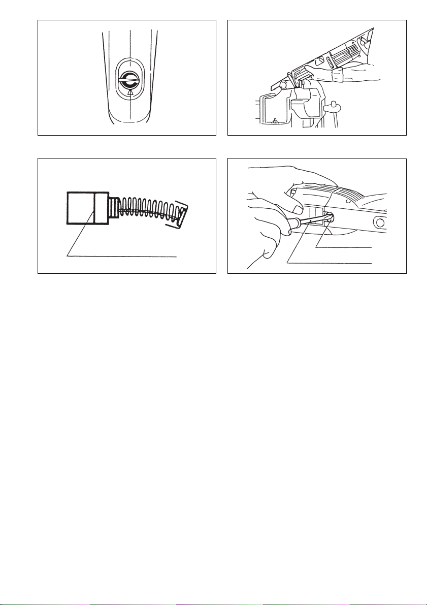
Switch action (Fig. 7, 8 & 9)
CAUTION:
Before plugging in the tool, always check to see that the
switch trigger actuates properly and returns to the “OFF”
position when released.
For tools with lock button
To start the tool, simply pull the trigger. Tool speed is
increased by increasing pressure on the trigger. Release
the trigger to stop.
Tool speed can be adjusted by turning the speed change
knob. When the portion with
adjacent to the pointer, faster speed can be obtained by
turning the knob clockwise.
When the portion with
to the pointer, full speed can be obtained.
Continuous operation can be performed only when the
knob is set to the full speed position. To perfor m continuous operation, pull the trigger fully and then push the lock
button up. To stop the tool from the locked position, pull
the trigger fully, then release it.
For tools with lock-off button
To prevent the trigger from being accidentally pulled, a
lock-off button is provided. To start the tool, push the
lock-off button up and pull the trigger. Tool speed is
increased by increasing pressure on the trigger. Release
the trigger to stop.
Tool speed can be adjusted by turning the speed change
knob. When the portion with
adjacent to the pointer, faster speed can be obtained by
turning the knob clockwise.
When the portion with
to the pointer, full speed can be obtained.
v mark is positioned
w mark is positioned adjacent
v mark is positioned
w mark is positioned adjacent
Operation (Fig. 10)
Press the shoe firmly against the workpiece. Do not allow
the tool to bounce. Bring the blade into light contact with
the workpiece. First, make a pilot groove, using a slower
speed. Then use a faster speed to continue cutting.
CAUTION:
• Always use a suitable coolant (cutting oil) when cutting metal. Failure to do so will cause premature
blade wear.
• Always wear gloves to protect your hands from hot
flying chips when cutting metal.
• Always press the shoe firmly against the workpiece
during operation. If the shoe is held away from the
workpiece during operation, strong vibration and/or
twisting will be produced, causing the blade to snap
dangerously.
• Be sure to always wear suitable eye protection
which conforms with current national standards.
MAINTENANCE
CAUTION:
Always be sure that the tool is switched off and
unplugged before carrying out any work on the tool.
Replacement of carbon brushes (Fig. 11 & 12)
Replace carbon brushes when they are wor n down to the
limit mark. Both identical carbon brushes should be
replaced at the same time.
To maintain product safety and reliability, repairs, maintenance or adjustment should be carried out by a Makita
Authorized Service Centre.
6
Page 7

NEDERLANDS
1 Inbussleutel nr. 4
2Pen
3Bout
4 Zaagas
5 Klemblok
6Gat
Verklaring van algemene gegevens
7 Zaagblad
8 Hendel
9 Schoen
10 Regelaar
11 Vastzetknop
12 Vastzetknop
13 Trekkerschakelaar
14 Snelheidsregelaarsknop
15 Wijzer
16 Limietmarkering
17 Koolborsteldop
18 Schroevedraaier
TECHNISCHE GEGEVENS
Model JR3020
Max. snijcapaciteit
Pijp...................................................................... 90 mm
Hout .................................................................... 90 mm
Slaglengte.............................................................. 30 mm
Aantal zaagbewegingen/min. ........................... 0 – 2 500
Totale lengte ........................................................ 463 mm
Netto gewicht.......................................................... 3,8 kg
• In verband met ononderbroken research en ontwikke-
ling behouden wij ons het recht voor bovenstaande
technische gegevens te wijzigen zonder voorafgaande
kennisgeving.
• Opmerking: De technische gegevens kunnen van land
tot land verschillen.
Stroomvoorziening
De machine mag alleen worden aangesloten op een
stroombron van hetzelfde voltage als aangegeven op de
naamplaat, en kan alleen op enkel-fase wisselstroom
worden gebruikt. De machine is dubbel-geïsoleerd volgens de Europese standaard en kan derhalve ook op
een niet-geaard stopcontact worden aangesloten.
Veiligheidswenken
Voor uw veiligheid dient u de bijgevoegde Veiligheidsvoorschriften nauwkeurig op te volgen.
AANVULLENDE
VEILIGHEIDSVOORSCHRIFTEN
1. Draag een hard hoofddeksel (veiligheidshelm), veiligheidsbril en/of gezichtsbescherming. Het is ook
zeer aanbevelenswaardig een stofmasker, oorbescherming en dikke handschoenen te dragen.
2. Kontroleer het zaagblad zorgvuldig op barsten of
beschadiging alvorens het gereedschap te
gebruiken. Een gebarsten of beschadigd zaagblad dient onmiddellijk te worden vervangen.
3. Probeer geen werkstukken te zagen die groter
zijn dan de in deze gebruiksaanwijzing gespecificeerde (in het bijzonder holle pijpen), aangezien breken van het zaagblad en ongelukken het
gevolg kunnen zijn. (Fig. 1)
4. Houd het gereedschap altijd stevig vast.
5. Als u het gereedschap op hoge plaatsen gebruikt,
zorg er dan voor dat er onder u niemand aanwezig is.
6. Richt het gereedschap nooit op iemand in uw
onmiddellijke nabijheid.
7. Kontroleer alvorens te zagen of er verborgen elektrische draden, waterpijpen en dergelijke aanwezig zijn die beschadigd zouden kunnen worden.
Doet dit er niet toe, stop dan eerst de spanningsof watertoevoer. Vermijd in ieder geval elektrische
schok die fataal kan zijn, of kortsluiting die brand
kan veroorzaken. Houd uitsluitend de geïsoleerde
handgrepen van het gereedschap vast om elektrische schok te vermijden ingeval u per ongeluk
een geladen draad doorzaagt. Waterpijpen dienen
eventueel eerst geledigd te worden.
8. Zorg er voor dat u tijdens het zagen het uiteinde
van het zaagblad nergens tegenaan stoot.
Beschadiging van het gereedschap of gevaarlijk
breken van het zaagblad kan hiervan het gevolg
zijn. (Fig. 2)
9. Pas op vallende afgezaagde delen, die u of anderen in uw nabijheid kunnen treffen.
10. Wees bij zagen van metaal op uw hoede voor
wegvliegende hete metaaldeeltjes.
11. Raak onmiddellijk na het zagen het zaagblad of
het werkstuk nooit aan; aangezien deze zeer
heet kan zijn en brandwonden kan veroorzaken.
12. Wanneer u tijdens het zagen het gereedschap
van het werkstuk verwijdert, zal een sterke reactie het gevolg zijn, die het zaagblad kan breken
of het gereedschap uit uw hand kan wegslaan.
Schakel derhalve het gereedschap altijd eerst uit
en wacht tot de zaag volledig tot stilstand is
voordat u het gereedschap van het werkstuk
afneemt.
BEWAAR DEZE VOORSCHRIFTEN.
15
Page 8

BEDIENINGSVOORSCHRIFTEN
Let op:
Kontroleer altijd of het gereedschap is uitgeschakeld en
de stekker uit het stopkontakt is getrokken alvorens het
zaagblad te installeren of te verwijderen, of de schoen bij
te stellen.
Installeren of verwijderen van het zaagblad
(Fig. 3 en 4)
Voor het installeren van het zaagblad dient de bout met
inbussleutel nr. 4 te worden losgedraaid. Steek het zaagblad vervolgens in tussen de bladveer en de zaagas totdat de pen op de zaagas in het gat in het zaagblad komt.
Draai daarna de bout stevig vast en kontroleer of het
zaagblad vastzit door eraan te trekken.
AT T E N T IE :
Wanneer de pen nog niet in het zaagbladgat zit en u draait
de bout vast, zal de pen of het zaagblad beschadiging
oplopen. Tijdens het zagen kan dan het zaagblad onverwachts uitgewor pen worden hetgeen zeer gevaarlijk is.
Voor het verwijderen van het zaagblad volgt u de bovenbeschreven procedure in omgekeerde volgorde.
Positie Zaagactie Toepassingen
0
Rechtlijnige zaagactie Voor zagen in zacht staal, roestvrij staal en plastic.
Zaagactie met kleine orbit Voor zagen in zacht staal, aluminium en hard hout.
I
Schone zaagsnede bij zagen in hout, triplex en multiplex.
Bijstellen van de schoen (Fig. 5)
Wanneer een bepaald gedeelte van het zaagblad niet
meer goed snijdt, stel dan de schoen bij om een ongebruikt scherp gedeelte van het zaagblad te benutten. Dit
kan de gebruiksduur van het zaagblad verlengen. Voor
het bijstellen van de schoen, wordt de hendel losgedrukt,
zoals in de illustratie aangegeven. Vervolgens wordt de
schoen in de gewenste positie gezet door deze naar
voren of naar achteren te schuiven. De hendel wordt
daarna weer vastgedrukt om de schoen vast te zetten.
Veranderen van de zaagactie (Fig. 6)
Het is mogelijk met dit gereedschap orbitaal of rechtlijnig
te zagen. Raadpleeg de onderstaande tabel voor het kiezen van de juiste en meest doeltreffende zaagactie. Voor
het veranderen van de zaagactie wordt de vastzetknop
ingedrukt en de regelaar ver volgens naar de gewenste
positie gedraaid. Laat daarna de vastzetknop los voor het
vastzetten van de regelaar.
Zaagactie met
middelmatige orbit
II
Zaagactie met grote orbit Voor snelzagen in hout, triplex en multiplex.
III
Voor zagen in hout, triplex en multiplex.
Voor snelzagen in aluminium en zacht staal.
Werking van de trekkerschakelaar (Fig. 7, 8 en 9)
AT T E N T IE :
Alvorens de stekker in een stopkontakt te steken, dient u
altijd te kontroleren of de trekkerschakelaar naar behoren
werkt en bij loslaten naar de “OFF” positie terugkeert.
Voor het starten van het gereedschap drukt u gewoon op
de trekkerschakelaar. Oefent u grotere druk op de schakelaar uit, dan wordt de zaagsnelheid groter. Voor het
stoppen van het gereedschap laat u de trekkerschakelaar
los.
16
De gereedschapssnelheid kunt u door middel van de
snelheidsregelaarsknop instellen. Wanneer het met het
v teken gemerkte gedeelte van de regelaarsknop aan
de kant wordt geplaatst waar de wijzer zich bevindt, dan
wordt door omdraaien van de regelaarsknop naar rechts
een grotere zaagsnelheid verkregen. Wanneer het met
w teken gemerkte gedeelte in de bovenbeschre-
het
ven positie wordt geplaatst, komt het gereedschap in de
topsnelheid.
Continu zagen is alleen mogelijk met de regelaarsknop in
de topsnelheidspositie. Hiertoe dient de trekkerschakelaaar volledig te worden ingedrukt en de vastzetknop vervolgens naar boven gedrukt. Om vanuit deze
vergrendelde topsnelheidspositie het gereedschap te
stoppen, wordt de trekkerschakelaar volledig ingedrukt
en daarna losgelaten.
Page 9

Bediening (Fig. 10)
Druk de schoen flink tegen het werkstuk aan. Zorg
ervoor dat het gereedschap geen schokken maakt.
Breng vervolgens het zaagblad in contact met het werkstuk. Maar eerst met lage zaagsnelheid een geleidegroef. U kunt daarna met grotere snelheid verder zagen.
AT T E N TI E :
• Gebruik voor zagen in metaal altijd een geschikt koelmiddel (snijolie). Laat u dit na dan zal de gebruiksduur
van het zaagblad voortijdig worden verkort.
• Trek voor zagen in metaal altijd handschoenen aan om
uw handen te beschermen tegen wegvliegende hete
metaaldeeltjes.
• Druk tijdens het zagen de schoen altijd flink tegen het
werkstuk aan. Als u tijdens het zagen de schoen van
het werkstuk afneemt, zullen sterke vibraties en/of
kromtrekken van het zaagblad het gevolg zijn. Het
zaagblad kan dan breken hetgeen zeer gevaarlijk is.
• Vergeet verder niet de in uw land goedgekeurde oogbescherming te dragen.
ONDERHOUD
LET OP:
Zorg er altijd voor dat de machine is uitgeschakeld en de
stekker uit het stopcontact is verwijderd vooraleer onderhoud aan de machine uit te voeren.
Vervangen van koolborstels (Fig. 11 en 12)
Vervang de borstels wanneer ze tot aan de limietmarkeringzijn afgesleten. Beide koolborstels dienen tegelijkertijd te worden vervangen.
Opdat het gereedschap veilig en betrouwbaar blijft, dienen alle reparaties, onderhoud of afstellingen te worden
uitgevoerd in een erkend Makita service centrum.
17
Page 10

ENGLISH
EC-DECLARATION OF CONFORMITY
The undersigned, Yasuhiko Kanzaki, authorized by
Makita Corporation, 3-11-8 Sumiyoshi-Cho, Anjo, Aichi
446-8502 Japan declares that this product
manufactured by Makita Corporation in Japan is in compliance with the following standards or standardized documents,
in accordance with Council Directives, 73/23/EEC,
89/336/EEC and 98/37/EC.
(Serial No. : series production)
HD400, EN50144, EN55014, EN61000
ITALIANO
DICHIARAZIONE DI CONFORMITÀ
CON LE NORME DELLA COMUNITÀ EUROPEA
Il sottoscritto Yasuhiko Kanzaki, con l’autorizzazione
della Makita Corporation, 3-11-8 Sumiyoshi-Cho, Anjo,
Aichi 446-8502 Japan, dichiara che questo prodotto
(Numero di serie: Produzione in serie)
fabbricato dalla Makita Corporation in Giappone è conformi alle direttive europee ripor tate di seguito:
HD400, EN50144, EN55014, EN61000
secondo le direttive del Consiglio 73/23/CEE,
89/336/CEE e 98/37/CE.
FRANÇAISE
DÉCLARATION DE CONFORMITÉ CE
Je soussigné, Yasuhiko Kanzaki, mandaté par Makita
Corporation, 3-11-8 Sumiyoshi-Cho, Anjo, Aichi 446-8502
Japan, déclare que ce produit
fabriqué par Makita Cor poration au Japon, est conformes
aux normes ou aux documents normalisés suivants,
conformément aux Directives du Conseil, 73/23/CEE,
89/336/CEE et 98/37/EG.
(No. de série: production en série)
HD400, EN50144, EN55014, EN61000
DEUTSCH
Hiermit erklär t der Unterzeichnete, Yasuhiko Kanzaki,
Bevollmächtigter von Makita Corporation, 3-11-8 Sumiyoshi-Cho, Anjo, Aichi 446-8502 Japan, daß dieses von der
Firma Makita Corporation in Japan hergestellte Produkt
gemäß den Ratsdirektiven 73/23/EWG, 89/336/EWG
und 98/37/EG mit den folgenden Normen bzw. Normendokumenten übereinstimmen:
CE-KONFORMITÄTSERKLÄRUNG
(Serien-Nr.: Serienproduktion)
HD400, EN50144, EN55014, EN61000.
NEDERLANDS
EG-VERKLARING VAN CONFORMITEIT
De ondergetekende, Yasuhiko Kanzaki, gevolmachtigd
door Makita Corporation, 3-11-8 Sumiyoshi-Cho, Anjo,
Aichi 446-8502 Japan verklaart dat dit produkt
vervaardigd door Makita Corporation in Japan voldoet aan
de volgende normen of genormaliseerde documenten,
in overeenstemming met de richtlijnen van de Raad
73/23/EEC, 89/336/EEC en 98/37/EC.
(Serienr. : serieproduktie)
HD400, EN50144, EN55014, EN61000
ESPAÑOL
DECLARACIÓN DE CONFORMIDAD DE LA CE
El abajo firmante, Yasuhiko Kanzaki, autorizado por
Makita Corporation, 3-11-8 Sumiyoshi-Cho, Anjo, Aichi
446-8502 Japan, declara que este producto
(Número de serie: producción en serie)
fabricado por Makita Cor poration en Japón cumple las
siguientes normas o documentos normalizados,
HD400, EN50144, EN55014, EN61000
de acuerdo con las directivas comunitarias, 73/23/EEC,
89/336/EEC y 98/37/CE.
34
Yasuhiko Kanzaki
Director Amministratore
Directeur Directeur
Direktor Director
CE 94
MAKITA INTERNATIONAL EUROPE LTD.
Michigan Drive, Tongwell, Milton Keynes,
Bucks MK15 8JD, ENGLAND
Page 11

PORTUGUÊS
DECLARAÇÃO DE CONFORMIDADE DA CE
O abaixo assinado, Yasuhiko Kanzaki, autorizado pela
Makita Corporation, 3-11-8 Sumiyoshi-Cho, Anjo, Aichi
446-8502 Japan, declara que este produto
fabricado pela Makita Corporation no Japão obedece às
seguintes normas ou documentos normalizados,
de acordo com as directivas 73/23/CEE, 89/336/CEE e
98/37/CE do Conselho.
(N. de série: produção em série)
HD400, EN50144, EN55014, EN61000
NORSK
Undertegnede, Yasuhiko Kanzaki, med fullmakt fra
Makita Corporation, 3-11-8 Sumiyoshi-Cho, Anjo, Aichi
446-8502 Japan bekrefter herved at dette produktet
fabrikert av Makita Corporation, Japan, er i overensstemmelse med følgende standarder eller standardiserte
dokumenter:
i samsvar med Råds-direktivene, 73/23/EEC,
89/336/EEC og 98/37/EC.
EUs SAMSVARS-ERKLÆRING
(Serienr. : serieproduksjon)
HD400, EN50144, EN55014, EN61000,
DANSK
EU-DEKLARATION OM KONFORMITET
Undertegnede, Yasuhiko Kanzaki, med fuldmagt fra
Makita Corporation, 3-11-8 Sumiyoshi-Cho, Anjo, Aichi
446-8502 Japan, erklærer hermed, at dette produkt
fremstillet af Makita Corporation i Japan, er i overensstemmelse med de følgende standarder eller normsæt-
tende dokumenter,
i overensstemmelse med Rådets Direktiver 73/23/EEC,
89/336/EEC og 98/37/EC.
(Løbenummer: serieproduktion)
HD400, EN50144, EN55014, EN61000
SVENSKA
EG-DEKLARATION OM ÖVERENSSTÄMMELSE
Undertecknad, Yasuhiko Kanzaki, auktoriserad av Makita
Corporation, 3-11-8 Sumiyoshi-Cho, Anjo, Aichi 446-8502
Japan deklarerar att denna produkt
tillverkad av Makita Corporation i Japan, uppfyller kraven
i följande standard eller standardiserade dokument,
HD400, EN50144, EN55014, EN61000
i enlighet med EG-direktiven 73/23/EEC, 89/336/EEC
och 98/37/EC.
(serienummer: serieproduktion)
SUOMI
VAKUUTUS EC-VASTAAVUUDESTA
Makita Corporation, 3-11-8 Sumiyoshi-Cho, Anjo, Aichi
446-8502 Japan valtuuttamana allekirjoittanut, Yasuhiko
Kanzaki, vakuuttaa että tämä tämä tuote
valmistanut Makita Corporation Japanissa vastaa seuraavia standardeja tai stardardoituja asiakirjoja
neuvoston direktiivien 73/23/EEC, 89/336/EEC ja
98/37/EC mukaisesti.
(Sarja nro : sarjan tuotantoa)
HD400, EN50144, EN55014, EN61000
ΕΛΛΗΝΙΚΑ
Ο υπογράφων, Yasuhiko Kanzaki, εξουσιοδοτηµένος
απ# την εταιρεία Makita Corporation, 3-11-8
Sumiyoshi-Cho, Anjo, Aichi 446-8502 Japan, δηλώνει
#τι αυτ# το προϊ#ν
κατασκευασµένο απ# την Εταιρεία Makita στην
Ιαπωνία, βρίσκεται σε συµφωνία µε τα ακ#λουθα
πρ#τυπα ή τυποποιηµένα έγγραφα,
σύµφωνα µε τις Οδηγίες του Συµβουλίου,
73/23/EEC, 89/336/EEC και 98/37/ΚE.
∆ΗΛΩΣΗ ΣΥΜΜΟΡΦΩΣΗΣ ΕΚ
(Αύξων Αρ.: παραγωγή σειράς)
HD400, EN50144, EN55014, EN61000
Yasuhiko Kanzaki
Director Direktor
DirektørJohtaja
Direktör ∆ιευθυντής
CE 94
MAKITA INTERNATIONAL EUROPE LTD.
Michigan Drive, Tongwell, Milton Keynes,
Bucks MK15 8JD, ENGLAND
35
Page 12

ENGLISH
The typical A-weighted noise levels are
The typical weighted root mean square acceleration
value is 8 m/s
Noise and Vibration
sound pressure level: 90 dB (A)
sound power level: 100 dB (A)
– Wear ear protection. –
2
.
PORTUGUÊS
Os níveis normais de ruído A são
nível de pressão de som: 90 dB (A)
nível do sum: 100 dB (A)
– Utilize protectores para os ouvidos –
O valor médio da aceleração é 8 m/s
Ruído e vibração
2
.
FRANÇAISE
Les niveaux de bruit pondérés A types sont:
niveau de pression sonore: 90 dB (A)
niveau de puissance du son: 100 dB (A)
L’accélération pondérée est de 8 m/s
Bruit et vibrations
– Porter des protecteurs anti-bruit. –
2
.
DEUTSCH
Geräusch- und Vibrationsentwicklung
Die typischen A-bewerteten Geräuschpegel betragen:
Schalldruckpegel: 90 dB (A)
Schalleistungspegel: 100 dB (A)
– Gehörschutz tragen. –
Der gewichtete Effektivwer t der Beschleunigung beträgt
2
.
8m/s
ITALIANO
I livelli del rumore pesati secondo la curva A sono:
Il valore quadratico medio di accellerazione è di 8 m/s
Rumore e vibrazione
Livello pressione sonora: 90 dB (A)
Livello potenza sonora: 100 dB (A)
– Indossare i paraorecchi. –
2
NEDERLANDS
De typische A-gewogen geluidsniveau’s zijn
De typische gewogen effectieve versnellingswaarde is
2
8m/s
Geluidsniveau en trilling
geluidsdrukniveau: 90 dB (A)
geluidsenergie-niveau: 100 dB (A)
– Draag oorbeschermers. –
.
DANSK
De typiske A-vægtede lydniveauer er
Den vægtede effektive accelerationsværdi er 8 m/s
Lyd og vibration
lydtryksniveau: 90 dB (A)
lydeffektniveau: 100 dB (A)
– Bær høreværn. –
SVENSKA
De typiska A-vägda bullernivåerna är
Det typiskt vägda effektivvärdet för acceleration är 8 m/s
Buller och vibration
ljudtrycksnivå: 90 dB (A)
ljudeffektnivå: 100 dB (A)
– Använd hörselskydd –
NORSK
De vanlige A-belastede støynivå er
.
Den vanlig belastede effektiv-verdi for akselerasjon er
2
.
8m/s
Støy og vibrasjon
lydtrykksnivå: 90 dB (A)
lydstyrkenivå: 100 dB (A)
– Benytt hørselvern. –
SUOMI
Tyypilliset A-painotetut melutasot ovat
Tyypillinen kiihtyvyyden painotettu tehollisarvo on 8 m/s
Melutaso ja tärinä
äänenpainetaso: 90 dB (A)
äänen tehotaso: 100 dB (A)
– Käytä kuulosuojaimia. –
2
.
2
.
2
.
ESPAÑOL
Los niveles típicos de ruido ponderados A son
El valor ponderado de la aceleración es de 8 m/s
Ruido y vibración
presión sonora: 90 dB (A)
nivel de potencia sonora: 100 dB (A)
– Póngase protectores en los oídos. –
36
ΕΛΛΗΝΙΚΑ
Οι τυπικές A-µετρούµενες εντάσεις ήχου είναι
2
.
Η τυπική αξία της µετρούµενης ρίζας του µέσου
τετραγώνου της επιτάχυνσης είναι 8 m/s
Θρυβος και κραδασµς
πίεση ήχου: 90 dB (A)
δύναµη του ήχου: 100 dB (A)
– Φοράτε ωτοασπίδες. –
2
.
Page 13

373839
Page 14

Page 15

Page 16

Makita Corporation
Anjo, Aichi, Japan
Made in Japan
883850E993
 Loading...