

Page 1
INSTRUCTION MANUAL
MANUEL D'INSTRUCTION
MANUAL DE INSTRUCCIONES
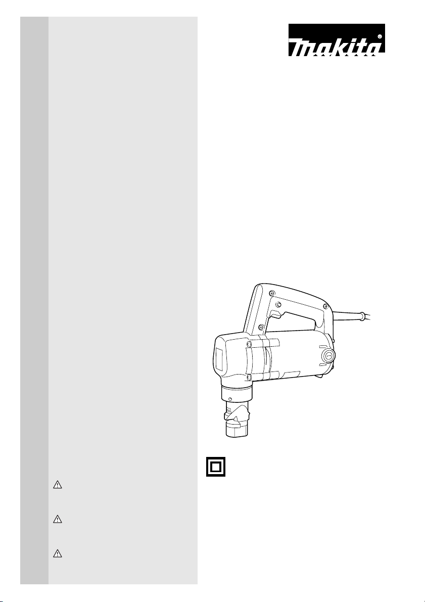
Nibbler
Grignoteuse
Roedora
JN3200
004773
DOUBLE INSULATION
DOUBLE ISOLATION
DOBLE AISLAMIENTO
WARNING:
For your personal safety, READ and UNDERSTAND before using.
SAVE THESE INSTRUCTIONS FOR FUTURE REFERENCE.
AVERTISSEMENT:
Pour votre propre sécurité, prière de lire attentivement avant l’utilisation.
GARDER CES INSTRUCTIONS POUR RÉFÉRENCE ULTÉRIEURE.
ADVERTENCIA:
Para su seguridad personal, LEA DETENIDAMENTE este manual antes de usar la herramienta.
GUARDE ESTAS INSTRUCCIONES PARA FUTURA REFERENCIA.
Page 2

ENGLISH
SPECIFICATIONS
Model JN3200
Mild steel 3.2 mm / 10 ga
Max. cutting capacities
Min. cutting radius
Strokes per minute 1,300
Overall length 215 mm (8-1/2”)
Net weight 3.4 kg (7.5 lbs)
• Due to our continuing programme of research and development, the specifications herein are subject to change
without notice.
• Note: Specifications may differ from country to country.
Stainless 2.5 mm / 13 ga
Aluminum 3.5 mm / 10 ga
Outside edge 128 mm (5-1/16”)
Inside edge 120 mm (4-3/4”)
GENERAL SAFETY RULES
GEA001-3
WARNING:
Read all instructions. Failure to follow all
instructions listed below may result in electric shock, fire and/or serious injury. The
term “power tool” in all of the warnings listed
below refers to your mains-operated
(corded) power tool or battery-operated
(cordless) power tool.
SAVE THESE INSTRUCTIONS
Work area safety
1. Keep work area clean and well lit. Cluttered and
dark areas invite accidents.
2. Do not operate power tools in explosive atmo-
spheres, such as in the presence of flammable
liquids, gases or dust. Power tools create sparks
which may ignite the dust or fumes.
3. Keep children and bystanders away while oper-
ating a power tool. Distractions can cause you to
lose control.
Electrical safety
4. Power tool plugs must match the outlet. Never
modify the plug in any way. Do not use any
adapter plugs with earthed (grounded) power
tools. Unmodified plugs and matching outlets will
reduce risk of electric shock.
5. Avoid body contact with earthed or grounded
surfaces such as pipes, radiators, ranges and
refrigerators. There is an increased risk of electric
shock if your body is earthed or grounded.
6. Do not expose power tools to rain or wet conditions. Water entering a power tool will increase the
risk of electric shock.
7. Do not abuse the cord. Never use the cord for
carrying, pulling or unplugging the power tool.
Keep cord away from heat, oil, sharp edges or
moving parts. Damaged or entangled cords
increase the risk of electric shock.
8. When operating a power tool outdoors, use an
extension cord suitable for outdoor use. Use of a
cord suitable for outdoor use reduces the risk of
electric shock.
Personal safety
9. Stay alert, watch what you are doing and use
common sense when operating a power tool. Do
not use a power tool while you are tired or under
the influence of drugs, alcohol or medication. A
moment of inattention while operating power tools
may result in serious personal injury.
10. Use safety equipment. Always wear eye protection. Safety equipment such as dust mask, non-skid
safety shoes, hard hat, or hearing protection used
for appropriate conditions will reduce personal injuries.
11. Avoid accidental starting. Ensure the switch is in
the off-position before plugging in. Carrying
power tools with your finger on the switch or plugging in power tools that have the switch on invites
accidents.
12. Remove any adjusting key or wrench before
turning the power tool on. A wrench or a key left
attached to a rotating part of the power tool may
result in personal injury.
2
Page 3

13. Do not overreach. Keep proper footing and balance at all times. This enables better control of the
power tool in unexpected situations.
14. Dress properly. Do not wear loose clothing or
jewellery. Keep your hair, clothing, and gloves
away from moving parts. Loose clothes, jewellery
or long hair can be caught in moving parts.
15. If devices are provided for the connection of
dust extraction and collection facilities, ensure
these are connected and properly used. Use of
these devices can reduce dust-related hazards.
Power tool use and care
16. Do not force the power tool. Use the correct
power tool for your application. The correct power
tool will do the job better and safer at the rate for
which it was designed.
17. Do not use the power tool if the switch does not
turn it on and off. Any power tool that cannot be
controlled with the switch is dangerous and must be
repaired.
18. Disconnect the plug from the power source and/
or the battery pack from the power tool before
making any adjustments, changing accessories,
or storing power tools. Such preventive safety
measures reduce the risk of starting the power tool
accidentally.
19. Store idle power tools out of the reach of children and do not allow persons unfamiliar with
the power tool or these instructions to operate
the power tool. Power tools are dangerous in the
hands of untrained users.
20. Maintain power tools. Check for misalignment or
binding of moving parts, breakage of parts and
any other condition that may affect the power
tools operation. If damaged, have the power tool
repaired before use. Many accidents are caused by
poorly maintained power tools.
21. Keep cutting tools sharp and clean. Properly
maintained cutting tools with sharp cutting edges
are less likely to bind and are easier to control.
22. Use the power tool, accessories and tool bits
etc. in accordance with these instructions and in
the manner intended for the particular type of
power tool, taking into account the working conditions and the work to be performed. Use of the
power tool for operations different from those
intended could result in a hazardous situation.
Service
23. Have your power tool serviced by a qualified
repair person using only identical replacement
parts. This will ensure that the safety of the power
tool is maintained.
24. Follow instruction for lubricating and changing
accessories.
25. Keep handles dry, clean and free from oil and
grease.
GEB028-1
SPECIFIC SAFETY RULES
DO NOT let comfort or familiarity with product
(gained from repeated use) replace strict adherence
to nibbler safety rules. If you use this tool unsafely or
incorrectly, you can suffer serious personal injury.
1. Hold the tool firmly.
2. Secure the workpiece firmly.
3. Keep hands away from moving parts.
4. Edges and chips of the workpiece are sharp.
Wear gloves. It is also recommended that you
put on thickly bottomed shoes to prevent injury.
5. Do not put the tool on the chips of the workpiece. Otherwise it can cause damage and trouble on the tool.
6. Do not leave the tool running. Operate the tool
only when hand-held.
7. Always be sure you have a firm footing.
Be sure no one is below when using the tool in
high locations.
8. Do not touch the punch, die or the workpiece
immediately after operation; they may be
extremely hot and could burn your skin.
9. Avoid cutting electrical wires. It can cause serious accident by electric shock.
SAVE THESE INSTRUCTIONS.
WARNING:
MISUSE or failure to follow the safety
rules stated in this instruction manual
may cause serious personal injury.
SYMBOLS
The followings show the symbols used for tool.
V ...........................volts
A...........................amperes
Hz .........................hertz
...................alternating current
.......................no load speed
.......................Class II Construction
.../min ...................revolutions or reciprocation per
minute
3
USD201-2
Page 4
FUNCTIONAL DESCRIPTION
ASSEMBLY
CAUTION:
• Always be sure that the tool is switched off and
unplugged before adjusting or checking function on
the tool.
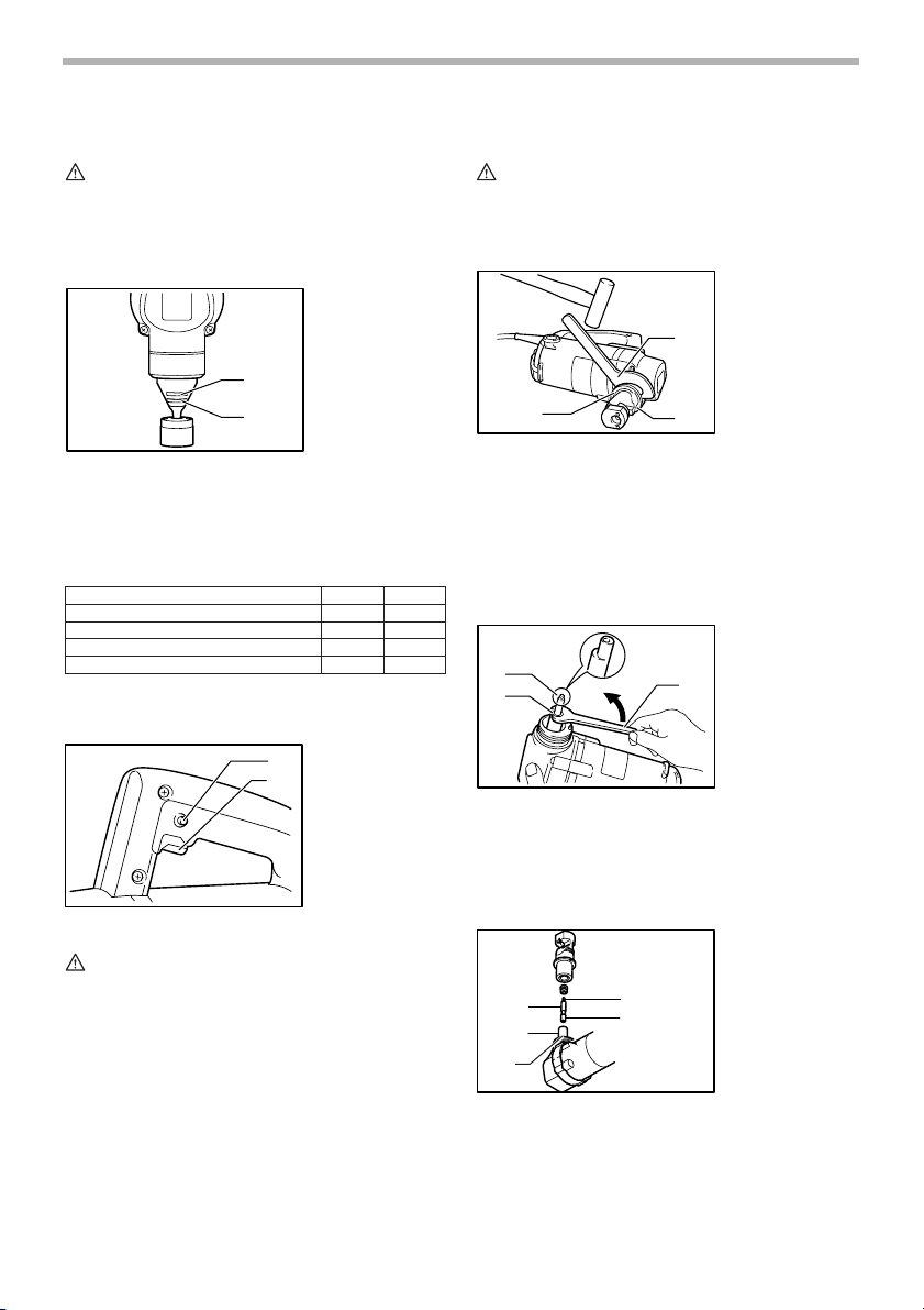
Permissible cutting thickness
004776
1. Stainless steel
gauge 2.5 mm
(3/32”)
2. Mild steel gauge
1
3.2 mm (1/8”)
2
The thickness of material to be cut depends upon the
tensile strength of the material itself. The groove on the
die holder acts as a thickness gauge for allowable cutting
thickness. Do not attempt to cut any material which will
not fit into this groove.
Max.cutting capacities mm ga
Steel up to 400 N/mm
Steel up to 600 N/mm
Steel up to 800 N/mm
Aluminum up to 200 N/mm
Switch action
2
2
2
2
004778
1
2
1. Lock button
2. Switch trigger
3.2 10
2.5 13
1.0 20
3.5 10
006439
CAUTION:
• Always be sure that the tool is switched off and
unplugged before carrying out any work on the tool.
Punch replacement
004783
1. Wrench
2. Lock nut
3. Die holder
1
2
3
Fit the wrench provided onto the lock nut and tap the
handle lightly with a hammer to loosen the lock nut. Take
off the die holder and use a wrench to remove the screw.
Then remove the punch.
To install the punch, insert it into the punch holder with its
cutting edge facing forward so that the pin in the punch
holder fits into the groove in the punch. Install the screw
and lock nut. Then tighten them securely.
004784
1. Punch
2. Screw
1
2
3
3. Wrench
CAUTION:
• Before plugging in the tool, always check to see
that the switch trigger actuates properly and returns
to the “OFF” position when released.
• Switch can be locked in “ON” position for ease of
operator comfort during extended use. Apply caution when locking tool in “ON” position and maintain
firm grasp on tool.
To start the tool, simply pull the switch trigger. Release
the switch trigger to stop.
For continuous operation, pull the switch trigger and then
push in the lock button.
To stop the tool from the locked position, pull the switch
trigger fully, then release it.
NOTE:
• When installing the screw and lock nut, be sure to
tighten securely. If they become loose during operation, the tool may break down.
004785
1. Cutting edge
2. Punch
2
4
1
3
3. Groove
4. Punch holder
5. Pin
5
4
Page 5
OPERATION
Pre-lubrication
Coat the cutting line with machine oil to increase the
punch and die service life. This is particularly important
when cutting aluminum.
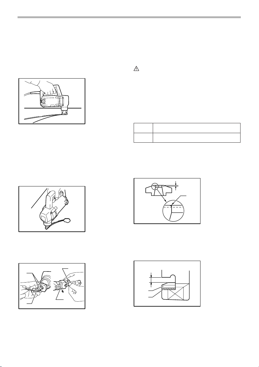
Cutting method
Smooth cutting is achieved by holding the tool upright
and applying gentle pressure in the cutting direction.
Apply tool oil to the punch about every 10 meters (32.8
feet) of mild steel or stainless steel to be cut. Light oil or
kerosene should be used to keep an aluminum lubricated
continuously. Failure to lubricate aluminum in the cut will
cause chips to adhere to the tool, dulling the die and
punch and increasing load on the motor.
Cutouts
004787
004789
Use the hex wrench provided to remove the two screws
and insert the washer below the die. Replace screws and
tighten securely.
MAINTENANCE
CAUTION:
• Always be sure that the tool is switched off and
unplugged before attempting to perform inspection
or maintenance.
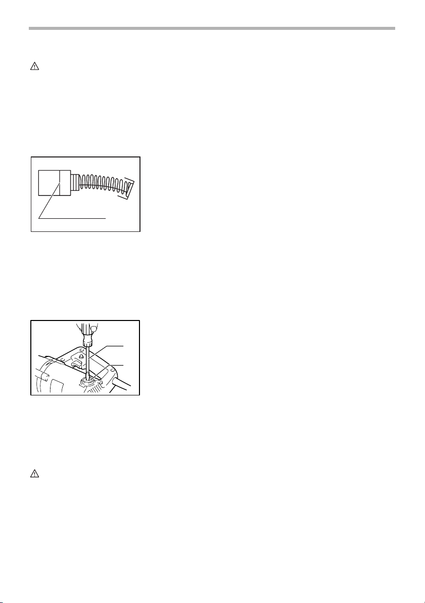
Punch & die service life
Replace or sharpen punch and die after cutting the
lengths indicated in the accompanying table. Their life, of
course, depends upon the thickness of materials cut and
lubrication conditions.
Punch Replace after 150 m (492 ft.) of 3.2 mm (1/8") steel sheet
Die Sharpen after 300 m (984 ft.) of 3.2 mm (1/8") steel sheet
When cutting is poor even after replacing the punch,
sharpen the die. Grind down the dull edge shown in the
figure using a grinder. After rough-grinding the dull portion, finish with a dressing stone. Stock removal should
be about 0.3 to 0.4 mm (1/64”).
004793
2
1. Grind/sharpen;
0.3 - 0.4 mm
(1/64”)
2. Remove dull
1
portion
006440
Cutouts can be done by first opening a round hole of
about 42 mm (1-5/8”) diameter or more in the material.
Cutting stainless steel
1
004792
3
1. Screw
2. Hex wrench
3. Washer
4. Insert washer in
between
4
2
5
5. Die
There is more vibration when cutting stainless steel than
mild steel. Less vibration and better cutting is possible by
adding another washer (standard equipment) beneath
the die.
When installing ground die, a clearance of 3.5 to 4.0 mm
(1/8” to 5/32”) should be obtained by attaching one or two
of the washer provided, as shown in the figure. Failure to
have the proper clearance will result in vibration during
cutting.
004794
1. 3.5 -4.0 mm
(1/8” - 5/32”)
2. Die
1
3. Washer
2
3
5
Page 6
CAUTION:
• Secure installing screws carefully when installing. A
loose screw can cause tool breakage during operation.
NOTE:
• The die can be sharpened two times. After two
sharpenings, it should be replaced with new one.
Replacing carbon brushes
Remove and check the carbon brushes regularly.
Replace when they wear down to the limit mark. Keep
the carbon brushes clean and free to slip in the holders.
Both carbon brushes should be replaced at the same
time. Use only identical carbon brushes.
Use a screwdriver to remove the brush holder caps. Take
out the worn carbon brushes, insert the new ones and
secure the brush holder caps.
To maintain product SAFETY and RELIABILITY, repairs,
any other maintenance or adjustment should be performed by Makita Authorized or Factory Service Centers,
always using Makita replacement parts.
001145
1. Limit mark
1
004796
1. Screwdriver
2. Brush holder
cap
1
2
ACCESSORIES
If you need any assistance for more details regarding
these accessories, ask your local Makita Service Center.
• Die
• Punch
• Hex wrench
• Wrench 50
• Die height adjustment washer
EN0006-1
MAKITA LIMITED ONE YEAR WARRANTY
Warranty Policy
Every Makita tool is thoroughly inspected and tested
before leaving the factory. It is warranted to be free of
defects from workmanship and materials for the period of
ONE YEAR from the date of original purchase. Should
any trouble develop during this one year period, return
the COMPLETE tool, freight prepaid, to one of Makita’s
Factory or Authorized Service Centers. If inspection
shows the trouble is caused by defective workmanship or
material, Makita will repair (or at our option, replace)
without charge.
This Warranty does not apply where:
• repairs have been made or attempted by others:
• repairs are required because of normal wear and
tear:
• the tool has been abused, misused or improperly
maintained:
• alterations have been made to the tool.
IN NO EVENT SHALL MAKITA BE LIABLE FOR ANY
INDIRECT, INCIDENTAL OR CONSEQUENTIAL DAMAGES FROM THE SALE OR USE OF THE PRODUCT.
THIS DISCLAIMER APPLIES BOTH DURING AND
AFTER THE TERM OF THIS WARRANTY.
MAKITA DISCLAIMS LIABILITY FOR ANY IMPLIED
WARRANTIES, INCLUDING IMPLIED WARRANTIES
OF “MERCHANTABILITY” AND “FITNESS FOR A SPECIFIC PURPOSE,” AFTER THE ONE YEAR TERM OF
THIS WARRANTY.
This Warranty gives you specific legal rights, and you
may also have other rights which vary from state to state.
Some states do not allow the exclusion or limitation of
incidental or consequential damages, so the above limitation or exclusion may not apply to you. Some states do
not allow limitation on how long an implied warranty lasts,
so the above limitation may not apply to you.
CAUTION:
• These accessories or attachments are recom-
mended for use with your Makita tool specified in
this manual. The use of any other accessories or
attachments might present a risk of injury to persons. Only use accessory or attachment for its
stated purpose.
6
Page 7

FRANÇAIS
SPÉCIFICATIONS
Modèle JN3200
Acier doux 3.2 mm / 10 ga
Capacités de coupe max.
Rayon de coupe min.
Nombre d’impacts par minutes 1,300
Longueur totale 215 mm (8-1/2”)
Poids net 3.4 kg (7.5 lbs)
• Le fabricant se réserve le droit de modifier sans avertissement les spécifications.
• Note: Les spécifications peuvent varier selon les pays.
Acier inoxydable 2.5 mm / 13 ga
Aluminium 3.5 mm / 10 ga
Bord extérieur 128 mm (5-1/16”)
Bord intérieur 120 mm (4-3/4”)
CONSIGNES DE SÉCURITÉ
GÉNÉRALES
GEA001-3
AVERTISSEMENT:
Veuillez lire l’ensemble des présentes
instructions. Il y a risque de choc
électrique, d’incendie et/ou de blessure
grave si toutes les instructions énumérées
ci-dessous ne sont pas respectées. Dans
tous les avertissements ci-dessous, le terme
“outil électrique” fait référence aux outils
électriques qui fonctionnent sur le secteur
(avec un cordon d’alimentation) et aux outils
électriques alimentés par batterie (sans
cordon d’alimentation).
CONSERVEZ CES
INSTRUCTIONS
Sécurité de la zone de travail
1. Maintenez la zone de travail propre et bien
éclairée. Les zones de travail encombrées et
sombres ouvrent grande la porte aux accidents.
2. N’utilisez pas les outils électriques dans des
atmosphères explosives, telles qu’en présence
de liquides, de gaz ou de poussières
inflammables. Les outils électriques produisent des
étincelles au contact desquelles la poussière ou les
vapeurs risqueraient de s’enflammer.
3. Assurez-vous qu’aucun enfant ou passant ne
s’approche pendant que vous utilisez un outil
électrique. Vous risquez de perdre la maîtrise de
l’outil si votre attention est détournée.
Sécurité en matière d’électricité
4. La fiche des outils électriques doit être conçue
pour la prise de courant utilisée. Ne modifiez
jamais la fiche de quelque façon que ce soit.
N’utilisez aucun adaptateur de fiche sur les
outils électriques avec mise à la terre. En ne
modifiant pas les fiches et en les insérant dans des
prises de courant pour lesquelles elles ont été
conçues vous réduirez les risques de choc
électrique.
5. Évitez tout contact corporel avec les surfaces
mises à la terre, telles que les tuyaux, radiateurs,
cuisinières et réfrigérateurs. Le risque de choc
électrique augmentera si votre corps se trouve mis à
la terre.
6. N’exposez pas les outils électriques à la pluie et
évitez qu’ils ne soient mouillés. Les risques de
choc électrique augmentent lorsque de l’eau
pénètre dans un outil électrique.
7. Ne maltraitez pas le cordon. N’utilisez jamais le
cordon pour transporter l’outil électrique, pour
tirer dessus ou pour le débrancher. Maintenez le
cordon à l’écart des sources de chaleur, de
l’huile, des objets à bords tranchants et des
pièces en mouvement. Le risque de choc
électrique augmente lorsque les cordons sont
endommagés ou enchevêtrés.
8. Lorsque vous utilisez un outil électrique à
l’extérieur, utilisez un cordon prolongateur prévu
à cette fin. Les risques de choc électrique
diminuent lorsqu’un cordon conçu pour l’extérieur
est utilisé.
7
Page 8

Sécurité personnelle
9. Restez alerte, attentif à vos mouvements et
faites preuve de bon sens lorsque vous utilisez
un outil électrique. Évitez d’utiliser un outil
électrique si vous êtes fatigué ou si vous avez
pris une drogue, de l’alcool ou un médicament.
Un moment d’inattention pendant l’utilisation d’un
outil électrique peut entraîner une grave blessure.
10. Utilisez des dispositifs de sécurité. Portez
toujours des lunettes de protection. Les risques
de blessure diminueront si vous utilisez des
dispositifs de sécurité tels qu’un masque
antipoussières, des chaussures à semelle
antidérapante, une coiffure résistante ou une
protection d’oreilles.
11. Prévenez tout démarrage accidentel. Assurezvous que l’interrupteur est en position d’arrêt
avant de brancher l’outil. Vous ouvrez toute
grande la porte aux accidents si vous transportez
les outils électriques en gardant le doigt sur la
gâchette ou si vous les branchez alors que
l’interrupteur se trouve en position de marche.
12. Retirez toute clé de réglage ou autre type de clé
avant de mettre l’outil sous tension. Toute clé
laissée en place sur une pièce rotative de l’outil
électrique peut entraîner une blessure.
13. Maintenez une position stable. Assurez-vous
d’avoir une bonne prise au sol et une bonne
position d’équilibre en tout temps. Vous aurez
ainsi une meilleure maîtrise de l’outil en cas de
situation imprévue.
14. Portez des vêtements adéquats. Ne portez ni
vêtements amples ni bijoux. Vous devez
maintenir cheveux, vêtements et gants à l’écart
des pièces en mouvement. Les pièces en
mouvement risqueraient de happer les vêtements
amples, les bijoux ou les cheveux longs.
15. Si des accessoires sont fournis pour raccorder
un appareil d’aspiration et de collecte de la
poussière, assurez-vous que les raccordements
sont corrects et que l’appareil est bien utilisé.
L’utilisation de tels accessoires permet de réduire
les risques liés à la présence de poussière dans l’air.
Utilisation et entretien des outils
électriques
16. Ne forcez pas l’outil électrique. Utilisez l’outil
électrique adéquat suivant le type de travail à
effectuer. Si vous utilisez l’outil électrique adéquat
et respectez le régime pour lequel il a été conçu, il
effectuera un travail de meilleure qualité et de façon
plus sécuritaire.
17. N’utilisez pas l’outil électrique s’il n’est pas
possible de mettre sa gâchette en position de
marche et d’arrêt. Un outil électrique dont
l’interrupteur est défectueux représente un danger et
doit être réparé.
18. Débranchez la fiche de la source d’alimentation
et/ou retirez le bloc-pile de l’outil électrique
avant d’effectuer tout réglage, de changer un
accessoire ou de ranger l’outil électrique. Ces
mesures préventives réduiront les risques de
démarrage accidentel de l’outil électrique.
19. Après l’utilisation d’un outil électrique, rangez-le
hors de portée des enfants et ne laissez aucune
personne l’utiliser si elle n’est pas familiarisée
avec l’outil électrique ou les présentes
instructions d’utilisation. Les outils électriques
représentent un danger entre les mains de
personnes qui n’en connaissent pas le mode
d’utilisation.
20. Ne négligez pas l’entretien des outils
électriques. Assurez-vous que les pièces
mobiles ne sont ni désalignées ni coincées,
qu’aucune pièce n’est cassée et que l’outil
électrique n’a subi aucun dommage pouvant
affecter son bon fonctionnement. Si l’outil
électrique est endommagé, faites-le réparer
avant de l’utiliser à nouveau. De nombreux
accidents sont causés par des outils électriques mal
entretenus.
21. Maintenez les outils tranchants bien aiguisés et
propres. Un outil tranchant dont l’entretien est
effectué correctement et dont les bords sont bien
aiguisés risquera moins de se coincer et sera plus
facile à maîtriser.
22. Utilisez l’outil électrique, ses accessoires, ses
embouts, etc., en respectant les présentes
instructions et de la façon prévue pour ce type
particulier d’outil électrique, en tenant compte
des conditions de travail et du type de travail à
effectuer. L’utilisation d’un outil électrique à des fins
autres que celles prévues est potentiellement
dangereuse.
Service
23. Faites réparer votre outil électrique par un
réparateur qualifié qui utilise des pièces de
rechange identiques aux pièces d’origine. Cela
permettra d’assurer le maintien de la sûreté de l’outil
électrique.
24. Suivez les instructions de lubrification et de
changement des accessoires.
25. Maintenez les poignées sèches, propres et
exemptes d’huile ou de graisse.
GEB028-1
RÈGLES DE SÉCURITÉ
PARTICULIÈRES
NE vous laissez PAS tromper (au fil d’une utilisation
répétée) par un sentiment d’aisance et de familiarité
avec l’outil, en négligeant le respect rigoureux des
règles de sécurité qui accompagnent la grignoteuse.
Si vous n’utilisez pas cet outil de façon sûre ou
adéquate, vous courez un risque de blessure grave.
8
Page 9

1. Tenez l’outil fermement.
2. Fixez la pièce à travailler solidement.
3. Gardez vos mains éloignées des pièces
mobiles.
4. Les bords et les copeaux de la pièce à travailler
sont coupants. Portez des gants. Il est
également recommandé de porter des
chaussures à semelle épaisse pour prévenir les
blessures.
5. Ne déposez pas l’outil sur les copeaux de la
pièce. Sinon, l’outil risque d’être endommagé et
de mal fonctionner.
6. N’abandonnez pas l’outil alors qu’il tourne. Ne
faites fonctionner l’outil qu’une fois que vous
l’avez bien en main.
7. Adoptez toujours une position de travail vous
assurant d’un bon équilibre.
Assurez-vous qu’il n’y a personne plus bas
lorsque vous utilisez l’outil en position élevée.
8. Ne touchez pas le poinçon, la matrice ou la
pièce immédiatement après l’opération ; ils
peuvent être extrêmement chauds et vous
brûler la peau.
9. Prenez garde de couper des fils électriques. Il
peut en résulter un grave accident par choc
électrique.
CONSERVEZ CE MODE
D’EMPLOI.
AVERTISSEMENT:
Une MAUVAISE UTILISATION de l’outil ou
l’ignorance des consignes de sécurité du
présent manuel d’instructions peuvent
entraîner une grave blessure.
SYMBOLES
Les symboles utilisés pour l’outil sont présentés cidessous.
V............................volts
A ...........................ampères
Hz..........................hertz
....................courant alternatif
.......................vitesse à vide
.......................construction, catégorie II
.../min....................tours ou alternances par minute
USD201-2
DESCRIPTION DU
FONCTIONNEMENT
ATTENTION:
• Assurez-vous toujours que l’outil est hors tension et
débranché avant de l’ajuster ou de vérifier son
fonctionnement.
Epaisseur de coupe admissible
L’épaisseur du matériau à découper dépend de la densité
du matériau lui-même. La rainure du porte-matrice sert
de gabarit d’épaisseur, indiquant l’épaisseur de coupe
permise. N’essayez pas de découper un matériau qui
n’entre pas dans la rainure.
Capacités de coupe max. mm ga
Acier jusqu'à 400 N/mm
Acier jusqu'à 600 N/mm
Acier jusqu'à 800 N/mm
Aluminium jusqu'à 200 N/mm
Interrupteur
ATTENTION:
• Avant de brancher l’outil, assurez-vous toujours
que la gâchette fonctionne correctement et revient
en position d’arrêt une fois relâchée.
• Pour rendre le travail de l’utilisateur plus confortable
lors d’une utilisation prolongée, l’interrupteur peut
être verrouillé en position de marche. Soyez
prudent lorsque vous verrouillez l’outil en position
de marche, et maintenez une poigne solide sur
l’outil.
004776
1. Gabarit pour
acier inoxydable
2.5 mm (3/32”)
2. Gabarit pour
1
acier doux
3.2 mm (1/8”)
2
006439
2
2
2
2
004778
1
2
3.2 10
2.5 13
1.0 20
3.5 10
1. Bouton de
verrouillage
2. Gâchette
9
Page 10

Pour fai re démarrer l’outil, appuyez simplement sur la
gâchette. Pour l’arrêter, relâchez la gâchette.
Pour une utilisation continue, tirez sur la gâchette et
appuyez sur le bouton de verrouillage.
Pour arrêter l’outil alors qu’il est en position verrouillée,
tirez à fond sur la gâchette puis relâchez-la.
ASSEMBLAGE
ATTENTION:
• Avant d’effectuer toute intervention sur l’outil,
assurez-vous toujours qu’il est hors tension et
débranché.
Remplacement du poinçon
004783
1
1. Clé
2. Contre-écrou
3. Porte-matrice
004785
1. Tranchant
2. Poinçon
2
4
5
1
3
3. Rainure
4. Porte-poinçon
5. Broche
UTILISATION
Prègraissage
Appliquez de l’huile à machine sur la ligne de coupe,
pour assurer une plus longue durée de service au
poinçon et à la matrice. Cela est tout particulièrement
important lorsque vous coupez dans l’aluminium.
Méthoded’usinage
004787
2
Placez la clé fournie sur le contre-écrou et frappez
légèrement sur la poignée avec un marteau pour
desserrer le contre-écrou. Enlevez le porte-matrice et
utilisez une clé pour retirer la vis. Retirez ensuite le
poinçon.
Pour remonter le poinçon, insérez-le dans le porte-
poinçon avec son tranchant tourné vers l’avant, de façon
que la goupille du porte-poinçon rentre dans la rainure
du poinçon. Installez la vis et le contre-écrou. Serrez-les
ensuite fermement.
1
2
NOTE:
• Lorsque vous installez la vis et le contre-écrou,
assurez-vous qu’ils sont bien serrés. L’outil risque
d’être endommagé s’ils se desserrent pendant
l’utilisation.
3
004784
3
1. Poinçon
2. Vis
3. Clé
Pour découper en douceur, tenez l’outil verticalement et
exercez une légère pression vers l’avant.
Appliquez de l’huile à machine sur le poinçon après
chaque coupe de 10 mètres (32.8 pieds) dans l’acier
doux ou dans l’acier inoxydable. Pour assurer la
lubrification continue de l’aluminium, il faut utiliser de
l’huile légère ou du kérosène. Si l’aluminium n’est pas
lubrifié pendant la coupe, les copeaux adhéreront à
l’outil, émousseront la matrice et le punch, imposant une
charge supplémentaire au moteur.
Découpage
Pour effectuer les découpes, commencez par forer un
orifice circulaire d’environ 42 mm (1-5/8”) de diamètre
minimum dans le matériau.
004789
10
Page 11

Coupe de l’acier inoxydable
1
004792
3
1. Vis
2. Clé hexagonale
3. Rondelle
4. Insérer la
rondelle
4
2
5
5. Matrice
La coupe de l’acier inoxydable cause plus de vibrations
que celle de l’acier doux. Il est possible de réduire les
vibrations et d’obtenir une meilleure coupe en ajoutant
une autre rondelle (fournie) sous la matrice.
Utilisez la clé hexagonale fournie pour retirer les deux vis
et insérez la rondelle sous la matrice. Remettez les vis
en place et serrez-les fermement.
ENTRETIEN
ATTENTION:
• Assurez-vous toujours que l’outil est hors tension et
débranché avant d’y effectuer tout travail
d’inspection ou d’entretien.
Usure du poinçon et de la matrice
Dès que les linéaires maxima indiqués dans le tableau
ci-dessous ont été atteints, le poinçon et la matrice
doivent être ou affûtés ou remplacés. L’usure des parties
coupantes sera fonction de l’épaisseur des tôles comme
de la lubrification.
Remplacer après 150 m (492 pieds) de coupe dans de
Poinçon
l'acier de 3.2 mm (1/8”) d'épais.
Affûter après 300 m (984 pieds) de coupe dans de l'acier
Matrice
de 3.2 mm (1/8”) d'épais.
006440
Lors de l’installation de la matrice, un jeu de 3.5 à
4.0 mm (1/8 à 5/32 po) doit être obtenu en fixant une ou
les deux rondelles fournies, tel qu’indiqué sur la figure.
L’outil vibrera pendant la coupe si un jeu adéquat n’est
pas fourni.
004794
1. 3.5 -4.0 mm
(1/8” - 5/32”)
2. Matrice
1
3. Rondelle
2
3
ATTENTION:
• Les vis doivent être installées avec soin lors de
l’installation des accessoires. Une vis mal serrée
peut causer des dommages à l’outil pendant
l’utilisation.
NOTE:
• Il est possible d’affûter la matrice deux fois. Après
deux affûtages, elle doit être remplacée par une
neuve.
Remplacement des charbons
001145
1. Trait de limite
d’usure
1
Affûtez la matrice si la coupe est médiocre même après
le remplacement du poinçon. Meulez le tranchant
émoussé, tel qu’indiqué sur l’illustration, à l’aide d’une
meuleuse. Après le dégrossissage à la meule de la
partie émoussée, effectuez le meulage de finition à l’aide
d’une pierre à dresser. La partie meulée doit être
d’environ 0.3 à 0.4 mm (1/64 po).
004793
2
1. Meulage/
affûtage :
0.3 - 0.4 (1/64”)
2. Retirer la partie
émoussée
1
Retirez et vérifiez régulièrement les charbons.
Remplacez-les lorsqu’ils sont usés jusqu’au trait de limite
d’usure. Maintenez les charbons propres et en état de
glisser aisément dans les porte-charbon. Les deux
charbons doivent être remplacés en même temps.
N’utilisez que des charbons identiques.
Utilisez un tournevis pour retirer les bouchons de portecharbon. Enlevez les charbons usés, insérez-en de
nouveaux et revissez solidement les bouchons de portecharbon.
11
Page 12

004796
1. Tournevis
2. Bouchon de
porte-charbon
1
2
Pour maintenir la SÉCURITÉ et la FIABILITÉ du produit,
les réparations, tout autre travail d’entretien ou de
réglage doivent être effectués dans un centre de service
Makita agréé ou un centre de service de l’usine Makita,
exclusivement avec des pièces de rechange Makita.
ACCESSOIRES
ATTENTION:
• Ces accessoires ou pièces complémentaires sont
recommandés pour l’utilisation avec l’outil Makita
spécifié dans ce mode d’emploi. L’utilisation de tout
autre accessoire ou pièce complémentaire peut
comporter un risque de blessure. N’utilisez les
accessoires ou pièces qu’aux fins auxquelles ils ont
été conçus.
Si vous désirez obtenir plus de détails concernant ces
accessoires, veuillez contacter le centre de service
après-vente Makita le plus près.
• Matrice
• Poinçon
• Clé hexagonale
• Clé 50
• Rondelle de réglage de hauteur de la matrice
GARANTIE LIMITÉE D’UN AN MAKITA
Politique de garantie
Chaque outil Makita est inspecté rigoureusement et testé
avant sa sortie d’usine. Nous garantissons qu’il sera
exempt de défaut de fabrication et de vice de matériau
pour une période d’UN AN à partir de la date de son
achat initial. Si un problème quelconque devait survenir
au cours de cette période d’un an, veuillez retourner
l’outil COMPLET, port payé, à une usine ou à un centre
de service après-vente Makita. Makita réparera l’outil
gratuitement (ou le remplacera, à sa discrétion) si un
défaut de fabrication ou un vice de matériau est
découvert lors de l’inspection.
Cette garantie ne s’applique pas dans les cas où:
• des réparations ont été effectuées ou tentées par
un tiers:
• des réparations s’imposent suite à une usure
normale:
• l’outil a été malmené, mal utilisé ou mal entretenu:
• l’outil a subi des modifications.
EN0006-1
MAKITA DÉCLINE TOUTE RESPONSABILITÉ POUR
TOUT DOMMAGE ACCESSOIRE OU INDIRECT LIÉ À
LA VENTE OU À L’UTILISATION DU PRODUIT. CET
AVIS DE NON-RESPONSABILITÉ S’APPLIQUE À LA
FOIS PENDANT ET APRÈS LA PÉRIODE COUVERTE
PAR CETTE GARANTIE.
MAKITA DÉCLINE TOUTE RESPONSABILITÉ QUANT
À TOUTE GARANTIE TACITE, INCLUANT LES
GARANTIES TACITES DE “QUALITÉ MARCHANDE” ET
“ADÉQUATION À UN USAGE PARTICULIER” APRÈS
LA PÉRIODE D’UN AN COUVERTE PAR CETTE
GARANTIE.
Cette garantie vous donne des droits spécifiques
reconnus par la loi, et possiblement d’autres droits, qui
varient d’un État à l’autre. Certains États ne permettant
pas l’exclusion ou la limitation des dommages
accessoires ou indirects, il se peut que la limitation ou
exclusion ci-dessus ne s’applique pas à vous. Certains
États ne permettant pas la limitation de la durée
d’application d’une garantie tacite, il se peut que la
limitation ci-dessus ne s’applique pas à vous.
12
Page 13

ESPAÑOL
ESPECIFICACIONES
Modelo JN3200
Especificaciones eléctricas en México
Acero templado 3,2 mm (10 ga)
Capacidad máxima de corte
Radio mínimo de corte
Carreras por minuto 1 300
Longitud total 215 mm (8-1/2”)
Peso neto 3,4 kg (7,5 lbs)
• Debido a un programa continuo de investigación y desarrollo, las especificaciones aquí dadas están sujetas a
cambios sin previo aviso.
• Nota: Las especificaciones pueden ser diferentes de país a país.
Acero inoxidable 2,5 mm (13 ga)
Aluminio 3,5 mm (10 ga)
Borde exterior 128 mm (5-1/16”)
Borde interior 120 mm (4-3/4”)
115 V 6 A 50/60 Hz
NORMAS GENERALES DE
SEGURIDAD
GEA001-3
AVISO:
Lea todas las instrucciones. Si no cumple
con las instrucciones aquí detalladas, se
puede producir una descarga eléctrica,
incendio y/o heridas de gravedad. El
término “herramienta eléctrica” en todas las
advertencias que figuran a continuación se
refiere a la herramienta eléctrica alimentada
por la red principal (con cable) o a la
operada por batería (sin cable).
GUARDE ESTAS
INSTRUCCIONES
Seguridad del área de trabajo
1. Mantenga el área de trabajo limpia y bien
iluminada. Las áreas oscuras y desordenadas son
propensas a accidentes.
2. No opere herramientas eléctricas en atmósferas
explosivas tales como en presencia de polvo,
gases o líquidos inflamables. Las herramientas
eléctricas producen chispas que puede encender el
polvo o los gases.
3. Mantenga a los niños y personas cercanas
alejadas mientras opera la herramienta eléctrica.
Si se distrae, puede perder el control de la
herramienta.
Seguridad eléctrica
4. El enchufe de la herramienta eléctrica debe
coincidir con la ficha. Nunca modifique el
enchufe. No use ningún adaptador con las
herramientas eléctricas a tierra (a masa). Los
enchufes sin modificar y las fichas correspondientes
reducen el riesgo de descarga eléctrica.
5. Evite el contacto corporal con superficies a
masa (a tierra) tales como radiadores, tuberías,
refrigeradores y hornillos. Se corre más riesgo de
sufrir una descarga eléctrica si el cuerpo está a
tierra.
6. No exponga las herramientas eléctricas a la
lluvia o a la humedad. Si ingresa agua en la
herramienta eléctrica, aumenta el riesgo de sufrir
una descarga eléctrica.
7. No tire del cable. Nunca utilice el cable para
transportar, tirar o desenchufar la herramienta
eléctrica. Mantenga el cable alejado del calor,
aceite, objetos cortantes o piezas móviles. Los
cables dañados o atrapados aumentan el riesgo de
sufrir una descarga eléctrica.
8. A la hora de operar una herramienta eléctrica en
el exterior, utilice un prolongador apropiado. Si
lo utiliza, se reduce el riesgo de sufrir una descarga
eléctrica.
Seguridad personal
9. Esté atento, preste atención a lo que está
haciendo y utilice su sentido común cuando
opere una herramienta eléctrica. No utilice la
herramienta eléctrica cuando esté cansado o
13
Page 14

bajo la influencia de drogas, alcohol o
medicamentos. Un momento de distracción
mientras opera la máquina puede dar como
resultado heridas personales graves.
10. Utilice equipos de seguridad. Utilice siempre
protección ocular. Los equipos de seguridad como
máscaras para protegerse del polvo, calzado
antideslizante o protección para los oídos, que se
utilizan en condiciones adecuadas, reducen el
riesgo de sufrir heridas personales.
11. Evite el encendido accidental de la herramienta.
Asegúrese de que el interruptor se encuentra en
posición de apagado (OFF) antes de enchufar la
herramienta. Si transporta la herramienta eléctrica
con su dedo en el interruptor o si enchufa la
herramienta cuando está encendida (ON) puede
haber accidentes.
12. Retire todas las llaves y tuercas de ajuste antes
de encender la herramienta eléctrica. Si deja
alguna de éstas adherida a una parte giratoria de la
herramienta eléctrica puede sufrir daños en su
persona.
13. No haga demasiadas cosas al mismo tiempo.
Mantenga la postura y el equilibrio en todo
momento. De esta manera, tendrá un mejor control
de la herramienta eléctrica en situaciones
inesperadas.
14. Utilice ropa adecuada. No utilice ropa holgada ni
joyas. Mantenga su cabello, ropa y guantes
alejados de las piezas móviles. La ropa holgada,
las joyas y el cabello pueden atascarse en las
piezas móviles.
15. Si se proveen dispositivos para la conexión de
extracción y recolección de polvo, asegúrese de
que estén correctamente conectados y sean
adecuadamente utilizados. La utilización de estos
dispositivos puede reducir los riesgos relacionados
con el polvo.
Mantenimiento y uso de la herramienta
eléctrica
16. No fuerce la herramienta eléctrica. Utilice la
herramienta eléctrica correcta para su
aplicación. La herramienta eléctrica adecuada hará
un trabajo mejor a la velocidad para la que ha sido
fabricada.
17. No utilice la herramienta eléctrica si el
interruptor no la enciende y apaga. Cualquier
herramienta eléctrica que no pueda ser controlada
con el interruptor es peligrosa y debe ser
reemplazada.
18. Desconecte el enchufe de la fuente de energía y/
o la batería de la herramienta eléctrica antes de
realizar ajustes, cambiar accesorios o guardar
las herramientas eléctricas. Dichas medidas de
seguridad preventivas reducen el riesgo de que la
herramienta se opere accidentalmente.
19. Guarde la herramienta eléctrica que no use fuera
del alcance de los niños y no permita que las
personas que no están familiarizadas con ella o
con las instrucciones la operen. Las herramientas
eléctricas son peligrosas en manos de personas
que no saben operarlas.
20. Realice el mantenimiento de la herramienta
eléctrica. Verifique que no esté mal alineada,
uniones de las partes móviles, piezas rotas y
demás condiciones que puedan afectar el
funcionamiento de la herramienta eléctrica. Si
está dañada, haga reparar la herramienta
eléctrica antes de utilizarla. Muchos accidentes
son causados por herramientas eléctricas que no
han recibido un mantenimiento adecuado.
21. Mantenga las herramientas de corte limpias y
filosas. Si recibe un mantenimiento adecuado y
tiene los bordes afilados, es probable que la
herramienta se atasque menos y sea más fácil
controlarla.
22. Utilice la herramienta eléctrica, accesorios,
brocas, etc. de acuerdo con estas instrucciones
y de la manera establecida para cada tipo de
unidad en particular; tenga en cuenta las
condiciones laborales y el trabajo a realizar. Si
utiliza la herramienta eléctrica para realizar
operaciones distintas de las indicadas, podrá
presentarse una situación peligrosa.
Servicio técnico
23. Haga que una persona calificada repare la
herramienta utilizando sólo piezas de repuesto
idénticas. Esto asegura que se mantenga la
seguridad de la herramienta eléctrica.
24. Siga las instrucciones para la lubricación y
cambio de accesorios.
25. Mantenga las asas secas, limpias y sin aceite o
grasa.
GEB028-1
NORMAS ESPECÍFICAS DE
SEGURIDAD
NO deje que la comodidad o familiaridad con el
producto (a base de utilizarlo repetidamente)
sustituya la estricta observancia de las normas de
seguridad para la roedora. Si utiliza esta herramienta
de forma no segura o incorrecta, podrá sufrir graves
lesiones personales.
1. Sostenga la herramienta con firmeza.
2. Fije la pieza de trabajo firmemente.
3. Mantenga las manos alejadas de las partes
móviles.
4. Los bordes y las astillas o virutas de la pieza de
trabajo son filosas. Use guantes. También se
recomienda que use calzado de suela gruesa
para prevenir lesiones.
14
Page 15

5. No coloque la herramienta sobre las virutas o
astillas de la pieza de trabajo. Si lo hace podría
averiar la herramienta y causar problemas en
su funcionamiento.
6. No deje la herramienta en marcha. Tenga en
marcha la herramienta solamente cuando la
tenga en la mano.
7. Asegúrese siempre de que tiene suelo firme.
Asegúrese de que no haya nadie debajo cuando
utilice la herramienta en lugares altos.
8. No toque el perforador, el troquel ni la pieza de
trabajo inmediatamente después de la
operación; podrían estar muy calientes y
producirle quemaduras de piel.
9. Evite cortar cables eléctricos. Podría causar un
accidente grave por descarga eléctrica.
GUARDE ESTAS
INSTRUCCIONES
AVISO:
El mal uso o incumplimiento de las
reglas de seguridad descriptas en el
presente manual de instrucciones puede
ocasionar graves lesiones personales.
SÍMBOLOS
USD201-2
A continuación se muestran los símbolos utilizados para
la herramienta.
V............................voltios
A ...........................amperios
Hz..........................hercios
....................corriente alterna
.......................velocidad en vacío
.......................Construcción clase II
.../min....................revoluciones, alternaciones o
carreras por minuto
DESCRIPCIÓN DEL
FUNCIONAMIENTO
PRECAUCIÓN:
• Asegúrese siempre de que la herramienta esté
apagada y desenchufada antes de ajustar o
comprobar cualquier función en la herramienta.
Grosor de corte permitido.
004776
1. Calibrador para
acero inoxidable
de 2,5 mm
(3/32”)
1
2
El grosor del material a ser cortado depende de la
resistencia de tensión del material en sí. La ranura en el
2. Calibrador para
acero dulce de
3,2 mm (1/8”)
sujetador del troquel funciona como un calibrador de
grosor para el grosor de corte permitido. No intente
cortar algún material que no pueda encajar en esta
ranura.
Capacidades máximas de corte mm ga
Acero de hasta 400 N/mm
Acero de hasta 600 N/mm
Acero de hasta 800 N/mm
Aluminio de hasta 200 N/mm
Accionamiento del interruptor
2
2
2
2
004778
1
2
1. Botón de
bloqueo
2. Gatillo
interruptor
3,2 10
2,5 13
1,0 20
3,5 10
006439
PRECAUCIÓN:
• Antes de enchufar la herramienta, compruebe
siempre que el gatillo interruptor se acciona
debidamente y que vuelve a la posición “OFF”
(apagado) cuando lo suelta.
• El interruptor puede ser bloqueado en la posición
“ON” (encendido) para mayor comodidad del
operario durante una utilización prolongada. Tenga
precaución cuando bloquee la herramienta en la
posición “ON” (encendido) y sujete la herramienta
firmemente.
Para encender la herramienta, simplemente jale el gatillo
interruptor. Suéltelo para apagar la herramienta.
Para operarla en forma continua, jale el gatillo y luego
pulse el botón de bloqueo.
Para destrabar la herramienta, jale el gatillo por
completo y luego suéltelo.
15
Page 16

MONTAJE
PRECAUCIÓN:
• Asegúrese siempre de que la herramienta esté
apagada y desenchufada antes de realizar
cualquier trabajo en la herramienta.
Reemplazo del perforador
004783
1
1. Llave
2. Tuerca
3. Sujetador del
troquel
OPERACIÓN
Prelubricado
Cubra la línea de corte con aceite para maquinara para
incrementar el tiempo de vida útil del perforador y el
troquel. Esto es particularmente importante al estar
cortando aluminio.
Método de corte
004787
2
Encaje la llave proporcionada en la tuerca de bloqueo y
para aflojarla golpetee la agarradera ligeramente con un
martillo. Retire el sujetador del troquel y use la llave para
quitar el tornillo. Luego retire el perforador.
Para instalar el perforador, insértelo en su sujetador con
su borde de corte hacia enfrente de tal forma que la
clavija en el sujetador del perforador encaje en la ranura
en el perforador. Coloque el tornillo y la tuerca de
bloqueo y apriételos fijamente.
1
2
NOTA:
• Al instalar el tornillo y la tuerca de bloqueo,
asegúrese de fijarlos firmemente. Si se aflojan
durante la operación, puede que la herramienta se
descomponga.
2
4
5
3
004784
1. Perforador
2. Tornillo
3. Llave
3
004785
1. Borde de corte
2. Perforador
1
3
3. Ranura
4. Sujetador del
perforador
5. Clavija
Un corte suave se logra al sostener la herramienta de
forma recta y al aplicar presión moderada hacia la
dirección de corte.
Aplique aceite para maquinaria al perforador
aproximadamente por cada 10 metros (32,8 pies) de
cortar acero dulce o acero inoxidable. El aceite ligero o
queroseno debería usarse para mantener el aluminio
lubricado constantemente. No lubricar el aluminio en el
corte generará virutas o astillas que se adherirán a la
herramienta, lo cual desafilará el troquel y el perforador
incrementando la carga en el motor.
Recortes
Los recortes pueden realizarse mediante la hechura
primero de un orificio redondo de aproximadamente
42 mm (1-5/8”) o más de diámetro en el material.
Corte de acero inoxidable
1
2
004789
004792
3
4
5
1. Tornillo
2. Llave hexagonal
3. Arandela
4. Insertar
arandela en
medio
5. Troquel
16
Page 17

Habrá mayor vibración al cortar acero inoxidable que al
cortar acero dulce. Es posible una menor vibración
durante el corte al añadir otra arandela (equipo estándar)
por debajo del troquel.
Use la llave hexagonal proporcionada para quitar los dos
tornillos e inserte la arandela debajo del troquel. Vuelva
a colocar los tornillos y fíjelos firmemente.
MANTENIMIENTO
PRECAUCIÓN:
• Asegúrese siempre que la herramienta esté
apagada y desenchufada antes de intentar realizar
una inspección o mantenimiento.
Vida útil del perforador y troquel
Reemplace o afile el perforador y troquel tras las
longitudes de corte que se indican en la tabla adjunta.
Por supuesto que el tiempo de vida útil depende del
grosor de los materiales cortados y de las condiciones
de lubricación.
Perforador
Afile el troquel cuando el corte es ineficiente incluso tras
haber reemplazado el perforador. Realice un desgaste
Reemplace tras 150 m (492 pies) de láminas de acero de
3,2 mm (1/8")
Afile tras 300 m (984 pies) de láminas de acero de
Troquel
3,2 mm (1/8")
del borde desafilado que se muestra en la figura con una
amoladora (lijadora). Después de realizar un desgaste
áspero en la sección desafilada, realice un acabado con
una piedra lijadora. La eliminación del material
excedente debe ser aproximadamente de 0,3 a 0,4 mm
(1/64”).
004793
2
1. Lijar/afilar; 0,3 –
0,4 mm (1/64”)
2. Eliminación de
porción
1
desafilada
Al instalar el troquel lijado, debe haber un despeje de 3,5
a 4,0 mm (de 1/8” a 5/32”) al colocar una o dos de las
arandelas proporcionadas como se muestra en la figura.
No dejar el despeje adecuado podría resultar en
vibración durante el corte.
006440
004794
1. 3,5 -4,0 mm
(1/8” - 5/32”)
2. Troquel
1
3. Arandela
2
3
PRECAUCIÓN:
• Fije los tornillos de instalación con cuidado al
instalar. Un tornillo suelto podría averiar la
herramienta durante la operación.
NOTA:
• El troquel puede ser afilado dos veces. Tras dos
afiladas, éste debe ser reemplazado con uno
nuevo.
Reemplazo de las escobillas de carbón
001145
1. Marca límite
1
Extraiga e inspeccione regularmente las escobillas de
carbón. Substitúyalas cuando se hayan gastado hasta la
marca límite. Mantenga las escobillas de carbón limpias
de forma que entren libremente en los portaescobillas.
Ambas escobillas de carbón deberán ser sustituidas al
mismo tiempo. Utilice únicamente escobillas de carbón
originales.
Utilice un destornillador para quitar los tapones
portaescobillas. Extraiga las escobillas gastadas, inserte
las nuevas y vuelva a colocar los tapones
portaescobillas.
004796
1. Destornillador
2. Tapa del carbón
1
2
17
Page 18

Para mantener la SEGURIDAD y FIABILIDAD del
producto, las reparaciones, y cualquier otra tarea de
mantenimiento o ajuste deberán ser realizadas en
Centros de Servicio Autorizados por Makita, empleando
siempre repuestos Makita.
ACCESORIOS
PRECAUCIÓN:
• Estos accesorios o acoplamientos están
recomendados para utilizar con su herramienta
Makita especificada en este manual. El empleo de
cualesquiera otros accesorios o acoplamientos
conllevará un riesgo de sufrir heridas personales.
Utilice los accesorios o acoplamientos solamente
para su fin establecido.
Si necesita cualquier ayuda para más detalles en
relación con estos accesorios, pregunte a su centro de
servicio Makita local.
• Troquel
• Perforador
• Llave hexagonal
• Llave 50
• Arandela de ajuste de la altura del troquel
GARANTÍA LIMITADA MAKITA DE UN AÑO
Política de garantía
Cada herramienta Makita es inspeccionada y probada
exhaustivamente antes de salir de fábrica. Se garantiza
que va a estar libre de defectos de mano de obra y
materiales por el periodo de UN AÑO a partir de la fecha
de adquisición original. Si durante este periodo de un
año se desarrollase algún problema, retorne la
herramienta COMPLETA, porte pagado con antelación, a
una de las fábricas o centros de servicio autorizados
Makita. Si la inspección muestra que el problema ha sido
causado por mano de obra o material defectuoso, Makita
la reparará (o a nuestra opción, reemplazará) sin cobrar.
Esta garantía no será aplicable cuando:
• se hayan hecho o intentado hacer reparaciones por
otros:
• se requieran reparaciones debido al desgaste
normal:
• la herramienta haya sido abusada, mal usada o
mantenido indebidamente:
• se hayan hecho alteraciones a la herramienta.
EN NINGÚN CASO MAKITA SE HARÁ RESPONSABLE
DE NINGÚN DAÑO INDIRECTO, FORTUITO O
CONSECUENCIAL DERIVADO DE LA VENTA O USO
DEL PRODUCTO.
ESTA RENUNCIA SERÁ APLICABLE TANTO
DURANTE COMO DESPUÉS DEL TÉRMINO DE ESTA
GARANTÍA.
MAKITA RENUNCIA LA RESPONSABILIDAD POR
CUALQUIER GARANTÍA IMPLÍCITA, INCLUYENDO
GARANTÍAS IMPLÍCITAS DE “COMERCIALIDAD” E
EN0006-1
“IDONEIDAD PARA UN FIN ESPECÍFICO”, DESPUÉS
DEL TÉRMINO DE UN AÑO DE ESTA GARANTÍA.
Esta garantía le concede a usted derechos legales
específicos, y usted podrá tener también otros derechos
que varían de un estado a otro. Algunos estados no
permiten la exclusión o limitación de daños fortuitos o
consecuenciales, por lo que es posible que la antedicha
limitación o exclusión no le sea de aplicación a usted.
Algunos estados no permiten limitación sobre la
duración de una garantía implícita, por lo que es posible
que la antedicha limitación no le sea de aplicación a
usted.
18
Page 19

19
Page 20

< USA only >
WARNING
Some dust created by power sanding, sawing, grinding, drilling, and other
construction activities contains chemicals known to the State of California
to cause cancer, birth defects or other reproductive harm. Some examples
of these chemicals are:
• lead from lead-based paints,
• crystalline silica from bricks and cement and other masonry products, and
• arsenic and chromium from chemically-treated lumber.
Your risk from these exposures varies, depending on how often you do this
type of work. To reduce your exposure to these chemicals: work in a well
ventilated area, and work with approved safety equipment, such as those
dust masks that are specially designed to filter out microscopic particles.
< USA solamente >
ADVERTENCIA
Algunos tipos de polvo creados por el lijado, serrado, amolado, taladrado, y
otras actividades de la construccion contienen sustancias quimicas
reconocidas por el Estado de California como causantes de cancer, defectos
de nacimiento y otros peligros de reproduccion. Algunos ejemplos de estos
productos quimicos son:
• plomo de pinturas a base de plomo,
• silice cristalino de ladrillos y cemento y otros productos de albanileria, y
• arsenico y cromo de maderas tratadas quimicamente.
El riesgo al que se expone variara, dependiendo de la frecuencia con la que
realice este tipo de trabajo. Para reducir la exposicion a estos productos
quimicos: trabaje en un area bien ventilada, y pongase el equipo de seguridad
indicado, tal como esas mascaras contra el polvo que estan especialmente
disenadas para filtrar particulas microscopicas.
Makita Corporation
3-11-8, Sumiyoshi-cho,
Anjo, Aichi 446-8502 Japan
883334-941
 Loading...