

Page 1
INSTRUCTION MANUAL
MANUEL D'INSTRUCTION
MANUAL DE INSTRUCCIONES
Nibbler
Grignoteuse
Roedora
JN1601
004772
DOUBLE INSULATION
DOUBLE ISOLATION
DOBLE AISLAMIENTO
WARNING:
For your personal safety, READ and UNDERSTAND before using.
SAVE THESE INSTRUCTIONS FOR FUTURE REFERENCE.
AVERTISSEMENT:
Pour votre propre sécurité, prière de lire attentivement avant l’utilisation.
GARDER CES INSTRUCTIONS POUR RÉFÉRENCE ULTÉRIEURE.
ADVERTENCIA:
Para su seguridad personal, LEA DETENIDAMENTE este manual antes de usar la herramienta.
GUARDE ESTAS INSTRUCCIONES PARA FUTURA REFERENCIA.
Page 2

ENGLISH
SPECIFICATIONS
Model JN1601
Mild steel 1.6 mm / 16 ga
Max. cutting capacities
Min. cutting radius
Strokes per minute 2,200
Overall length 261 mm (10-1/4”)
Net weight 1.6 kg (3.5 lbs)
• Due to our continuing programme of research and development, the specifications herein are subject to change
without notice.
• Note: Specifications may differ from country to country.
Stainless 1.2 mm / 18 ga
Aluminum 2.5 mm / 13 ga
Outside edge 50 mm (2”)
Inside edge 45 mm (1-25/32”)
GENERAL SAFETY RULES
USA002-2
(For All Tools)
WARNING:
Read and understand all instructions.
Failure to follow all instructions listed below,
may result in electric shock, fire and/or serious personal injury.
SAVE THESE INSTRUCTIONS
Work Area
1. Keep your work area clean and well lit. Cluttered
benches and dark areas invite accidents.
2. Do not operate power tools in explosive atmo-
spheres, such as in the presence of flammable
liquids, gases, or dust. Power tools create sparks
which may ignite the dust or fumes.
3. Keep bystanders, children, and visitors away
while operating a power tool. Distractions can
cause you to lose control.
Electrical Safety
4. Double insulated tools are equipped with a
polarized plug (one blade is wider than the
other.) This plug will fit in a polarized outlet only
one way. If the plug does not fit fully in the outlet,
reverse the plug. If it still does not fit, contact a
qualified electrician to install a polarized outlet.
Do not change the plug in any way. Double insula-
tion eliminates the need for the three wire
grounded power cord and grounded power supply
system.
5. Avoid body contact with grounded surfaces
such as pipes, radiators, ranges and refrigerators. There is an increased risk of electric shock if
your body is grounded.
6. Do not expose power tools to rain or wet conditions. Water entering a power tool will increase the
risk of electric shock.
7. Do not abuse the cord. Never use the cord to
carry the tools or pull the plug from an outlet.
Keep cord away from heat, oil, sharp edges or
moving parts. Replace damaged cords immediately. Damaged cords increase the risk of electric
shock.
8. When operating a power tool outside, use an
outdoor extension cord marked “W-A” or “W”.
These cords are rated for outdoor use and reduce
the risk of electric shock.
Personal Safety
9. Stay alert, watch what you are doing and use
common sense when operating a power tool. Do
not use tool while tired or under the influence of
drugs, alcohol, or medication. A moment of inat-
tention while operating power tools may result in
serious personal injury.
10. Dress properly. Do not wear loose clothing or
jewelry. Contain long hair. Keep your hair, clothing, and gloves away from moving parts. Loose
clothes, jewelry, or long hair can be caught in moving parts.
11. Avoid accidental starting. Be sure switch is off
before plugging in. Carrying tools with your finger
on the switch or plugging in tools that have the
switch on invites accidents.
12. Remove adjusting keys or wrenches before turning the tool on. A wrench or a key that is left
2
Page 3

attached to a rotating part of the tool may result in
personal injury.
13. Do not overreach. Keep proper footing and balance at all times. Proper footing and balance
enables better control of the tool in unexpected situations.
14. Use safety equipment. Always wear eye protection. Dust mask, non-skid safety shoes, hard hat, or
hearing protection must be used for appropriate conditions. Ordinary eye or sun glasses are NOT eye
protection.
Tool Use and Care
15. Use clamps or other practical way to secure and
support the workpiece to a stable platform. Hold-
ing the work by hand or against your body is unstable and may lead to loss of control.
16. Do not force tool. Use the correct tool for your
application. The correct tool will do the job better
and safer at the rate for which it is designed.
17. Do not use tool if switch does not turn it on or
off. Any tool that cannot be controlled with the
switch is dangerous and must be repaired.
18. Disconnect the plug from the power source
before making any adjustments, changing
accessories, or storing the tool. Such preventive
safety measures reduce the risk of starting the tool
accidentally.
19. Store idle tools out of reach of children and
other untrained persons. Tools are dangerous in
the hands of untrained users.
20. Maintain tools with care. Keep cutting tools
sharp and clean. Properly maintained tools with
sharp cutting edges are less likely to bind and are
easier to control.
21. Check for misalignment or binding of moving
parts, breakage of parts, and any other condition
that may affect the tools operation. If damaged,
have the tool serviced before using. Many acci-
dents are caused by poorly maintained tools.
22. Use only accessories that are recommended by
the manufacturer for your model. Accessories
that may be suitable for one tool, may become hazardous when used on another tool.
SERVICE
23. Tool service must be performed only by qualified
repair personnel. Service or maintenance per-
formed by unqualified personnel could result in a risk
of injury.
24. When servicing a tool, use only identical
replacement parts. Follow instructions in the
Maintenance section of this manual. Use of unau-
thorized parts or failure to follow Maintenance
instructions may create a risk of electric shock or
injury.
USE PROPER EXTENSION CORD: Make sure your
extension cord is in good condition. When using an
extension cord, be sure to use one heavy enough to
carry the current your product will draw. An undersized
cord will cause a drop in line voltage resulting in loss of
power and overheating. Table 1 shows the correct size to
use depending on cord length and nameplate ampere
rating. If in doubt, use the next heavier gage. The smaller
the gage number, the heavier the cord.
Table 1: Minimum gage for cord
Ampere Rating
Volts Total length of cord in feet
120 V 25 ft. 50 ft. 100 ft. 150 ft.
More Than Not More Than AWG
0 6 18 16 16 14
18 16 14 12610
10 12 16 16 14 12
12 16 14 12
Not Recommended
GEB028-1
SPECIFIC SAFETY RULES
DO NOT let comfort or familiarity with product
(gained from repeated use) replace strict adherence
to nibbler safety rules. If you use this tool unsafely or
incorrectly, you can suffer serious personal injury.
1. Hold the tool firmly.
2. Secure the workpiece firmly.
3. Keep hands away from moving parts.
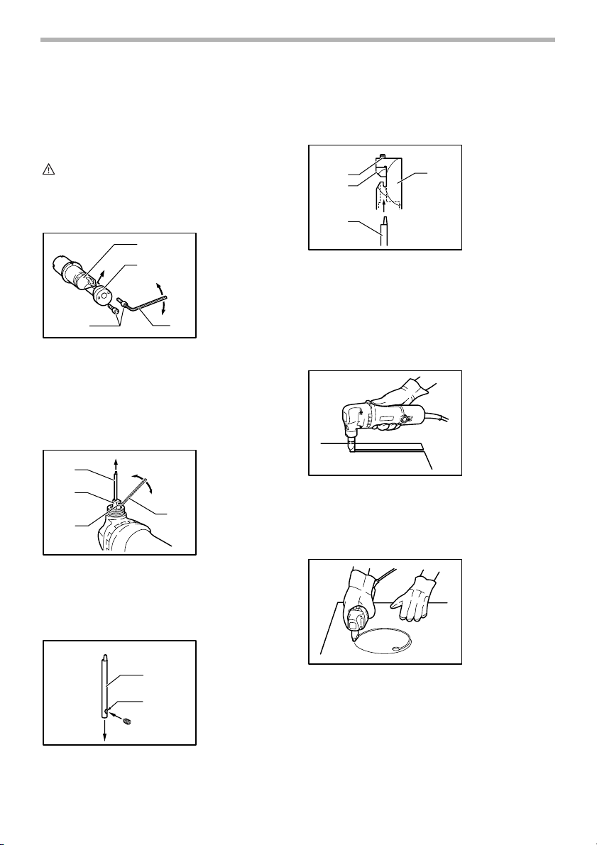
4. Edges and chips of the workpiece are sharp.
Wear gloves. It is also recommended that you
put on thickly bottomed shoes to prevent injury.
5. Do not put the tool on the chips of the workpiece. Otherwise it can cause damage and trouble on the tool.
6. Do not leave the tool running. Operate the tool
only when hand-held.
7. Always be sure you have a firm footing.
Be sure no one is below when using the tool in
high locations.
3
Page 4
8. Do not touch the punch, die or the workpiece
immediately after operation; they may be
extremely hot and could burn your skin.
9. Avoid cutting electrical wires. It can cause serious accident by electric shock.
SAVE THESE INSTRUCTIONS.
WARNING:
MISUSE or failure to follow the safety
rules stated in this instruction manual
may cause serious personal injury.
SYMBOLS
The followings show the symbols used for tool.
V............................volts
A ...........................amperes
Hz..........................hertz
....................alternating current
.......................no load speed
.......................Class II Construction
.../min....................revolutions or reciprocation per
minute
USD201-2
FUNCTIONAL DESCRIPTION
CAUTION:
• Always be sure that the tool is switched off and
unplugged before adjusting or checking function on
the tool.
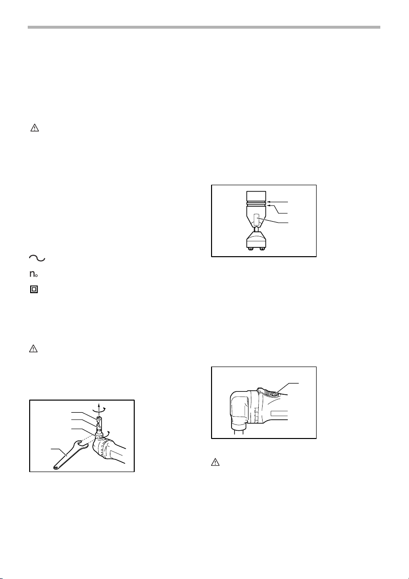
Changing the die position
1
2
3
004774
1. Die
2. Die holder
3. Lock nut
4. Wrench
3. Tighten the lock nut to secure the die holder in the
desired position.
There are four positive stops at 90° each: 0°, 90° left and
right and 180°. To position the die to any of these positive
stops:
1. Loosen the lock nut with the wrench provided.
2. Pull the die holder slightly and depress lightly while
turning it to the desired position. The die holder will
lock into one of the positive stop positions as
desired.
3. Turn the die holder slightly to make sure that it is
positively locked into position.
4. Tighten the lock nut to secure the die holder.
Permissible cutting thickness
The thickness of material to be cut depends upon the
tensile strength of the material itself. The groove on the
die holder acts as a thickness gauge for allowable cutting
thickness. Do not attempt to cut any material which will
not fit into this groove.
Cutting line
The notch in the die holder indicates your cutting line. Its
width is equal to the cutting width. Align the notch to the
cutting line on the workpiece when cutting.
Switch action
004775
1. Gauge for cut-
2. Gauge for cut-
3. Notch
004777
1. Switch lever
1
ting stainless:
1.2 mm (3/64”)
ting mild steel:
1.6 mm (1/16”)
1
2
3
4
The die position can be changed 360°. To change it, pro-
ceed as follows.
1. Loosen the lock nut with the wrench provided.
2. Pull the die holder slightly and turn it to the desired
position for operation.
CAUTION:
• Before plugging in the tool, always check to see
that the switch actuates properly and returns to the
“OFF” position when the rear of the switch lever is
depressed.
• Switch can be locked in “ON” position for ease of
operator comfort during extended use. Apply caution when locking tool in “ON” position and maintain
firm grasp on tool.
4
Page 5
To switch on, depress the rear of the switch lever and
push it forward. Then depress the front of the switch lever
to lock it.
To switch off, depress the rear of the switch lever.
ASSEMBLY
CAUTION:
• Always be sure that the tool is switched off and
unplugged before carrying out any work on the tool.
Removing or installing the punch and die
3
Always replace the punch and die as a set. To remove
the punch and die, loosen the lock nut with the wrench.
Remove the die holder from the tool. Use the hex wrench
to loosen the bolts which secure the die. Remove the die
from the die holder.
Use the hex wrench to loosen the screw which secures
the punch. Pull the punch out of the punch holder.
1
2
3
004779
1
2
1. Die holder
2. Die
3. Bolts
4. Hex wrench
4
004780
1. Punch
2. Punch holder
3. Screw
4. Hex wrench
4
Then install the die holder on the tool so that the punch is
inserted through the hole in the die holder. Tighten the
lock nut to secure the die holder. After replacing the
punch and die, lubricate them with machine oil and run
the tool for a while.
1
2
3
4
004782
1. Bolts
2. Die
3. Punch
4. Die holder
OPERATION
Pre-lubrication
Coat the cutting line with machine oil to increase the
punch and die service life. This is particularly important
when cutting aluminum.
Cutting method
Hold the tool so that the cutting head is at a right angle
(90°) to the workpiece being cut. Move the tool gently in
the cutting direction.
Cutouts
004786
004788
To install the punch and die, insert the punch into the
punch holder so that the notch in the punch faces toward
the screw. Tighten the screw to secure the punch. Install
the die on the die holder. Tighten the bolts to secure the
die.
004781
1. Punch
2. Notch
1
2
Cutouts can be done by first opening a round hole over
21 mm (13/16”) in diameter which the cutting head can
be inserted into.
5
Page 6
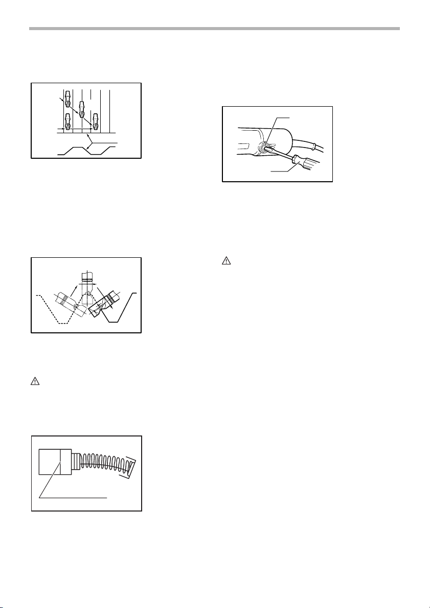
Cutting the corrugated or trapezoidal sheet
metals
1
2
3
4
004790
5
1. From the top
view
2. Cutting at an
angle to grooves
3. Cutting perpendicular to
grooves
4. From the side
view
5. Corrugated or
trapezoidal
sheet metal
Both carbon brushes should be replaced at the same
time. Use only identical carbon brushes.
Use a screwdriver to remove the brush holder caps. Take
out the worn carbon brushes, insert the new ones and
secure the brush holder caps.
2
004795
1
1. Brush holder
cap
2. Screwdriver
Set the die position so that the die faces the cutting direction either when cutting at an angle or perpendicular go
grooves in corrugated or trapezoidal sheet metals.
Always hold the tool body parallel to the grooves with the
cutting head at a right angle (90°) to the cutting surface
as shown in the figure.
12
004791
1. From the side
2. Cutting head
view
should be at a
right angle (90°)
to cutting surface.
MAINTENANCE
CAUTION:
• Always be sure that the tool is switched off and
unplugged before attempting to perform inspection
or maintenance.
Replacing carbon brushes
Remove and check the carbon brushes regularly.
Replace when they wear down to the limit mark. Keep
the carbon brushes clean and free to slip in the holders.
001145
1. Limit mark
1
To maintain product SAFETY and RELIABILITY, repairs,
any other maintenance or adjustment should be performed by Makita Authorized or Factory Service Centers,
always using Makita replacement parts.
ACCESSORIES
CAUTION:
• These accessories or attachments are recom-
mended for use with your Makita tool specified in
this manual. The use of any other accessories or
attachments might present a risk of injury to persons. Only use accessory or attachment for its
stated purpose.
If you need any assistance for more details regarding
these accessories, ask your local Makita Service Center.
• Die
• Punch
• Hex wrench
• Wrench 32
MAKITA LIMITED ONE YEAR WARRANTY
Warranty Policy
Every Makita tool is thoroughly inspected and tested
before leaving the factory. It is warranted to be free of
defects from workmanship and materials for the period of
ONE YEAR from the date of original purchase. Should
any trouble develop during this one year period, return
the COMPLETE tool, freight prepaid, to one of Makita’s
Factory or Authorized Service Centers. If inspection
shows the trouble is caused by defective workmanship or
material, Makita will repair (or at our option, replace)
without charge.
This Warranty does not apply where:
• repairs have been made or attempted by others:
• repairs are required because of normal wear and
tear:
• the tool has been abused, misused or improperly
maintained:
• alterations have been made to the tool.
EN0006-1
6
Page 7

IN NO EVENT SHALL MAKITA BE LIABLE FOR ANY
INDIRECT, INCIDENTAL OR CONSEQUENTIAL DAMAGES FROM THE SALE OR USE OF THE PRODUCT.
THIS DISCLAIMER APPLIES BOTH DURING AND
AFTER THE TERM OF THIS WARRANTY.
MAKITA DISCLAIMS LIABILITY FOR ANY IMPLIED
WARRANTIES, INCLUDING IMPLIED WARRANTIES
OF “MERCHANTABILITY” AND “FITNESS FOR A SPECIFIC PURPOSE,” AFTER THE ONE YEAR TERM OF
THIS WARRANTY.
This Warranty gives you specific legal rights, and you
may also have other rights which vary from state to state.
Some states do not allow the exclusion or limitation of
incidental or consequential damages, so the above limitation or exclusion may not apply to you. Some states do
not allow limitation on how long an implied warranty lasts,
so the above limitation may not apply to you.
7
Page 8

FRANÇAIS
SPÉCIFICATIONS
Modèle JN1601
Acier doux 1.6 mm / 16 ga
Capacités de coupe max.
Rayon de coupe min.
Nombre d’impacts par minutes 2,200
Longueur totale 261 mm (10-1/4”)
Poids net 1.6 kg (3.5 lbs)
• Le fabricant se réserve le droit de modifier sans avertissement les spécifications.
• Note: Les spécifications peuvent varier selon les pays.
Acier inoxydable 1.2 mm / 18 ga
Aluminium 2.5 mm / 13 ga
Bord extérieur 50 mm (2”)
Bord intérieur 45 mm (1-25/32”)
RÈGLES DE SÉCURITÉ
GÉNÉRALES
USA002-2
(Pour tous les outils)
AVERTISSEMENT:
Vous devez lire et comprendre toutes les
instructions. Le non-respect, même partiel,
des instructions ci-après entraîne un risque
de choc électrique, d’incendie et/ou de
blessures graves.
CONSERVEZ CES
INSTRUCTIONS
Aire de travail
1. Veillez à ce que l’aire de travail soit propre et
bien éclairée. Le désordre et le manque de lumière
favorisent les accidents.
2. N’utilisez pas d’outils électriques dans une
atmosphère explosive, par exemple en présence
de liquides, de gaz ou de poussières
inflammables. Les outils électriques créent des
étincelles qui pourraient enflammer les poussières
ou les vapeurs.
3. Tenez à distance les curieux, les enfants et les
visiteurs pendant que vous travaillez avec un
outil électrique. lls pourraient vous distraire et vous
faire une fausse manoeuvre.
Sécurité électrique
4. Les outils à double isolation sont équipés d’une
fiche polarisée (une des lames est plus large que
l’autre), qui ne peut se brancher que d'une seule
façon dans une prise polarisée. Si la fiche
n’entre pas parfaitement dans la prise, inversez
sa position ; si elle n’entre toujours pas bien,
demandez à un électricien qualifié d’installer une
prise de courant polarisée. Ne modifiez pas la
fiche de l’outil. La double isolation élimine le
besoin d’un cordon d’alimentation à trois fils avec
mise à la terre ainsi que d’une prise de courant mise
à la terre.
5. Évitez tout contact corporel avec des surfaces
mises à la terre (tuyauterie, radiateurs,
cuisinières, réfrigérateurs, etc.). Le risque de
choc électrique est plus grand si votre corps est en
contact avec la terre.
6. N’exposez pas les outils électriques à la pluie ou
à l’eau. La présence d’eau dans un outil électrique
augmente le risque de choc électrique.
7. Ne maltraitez pas le cordon. Ne transportez pas
l’outil par son cordon et ne débranchez pas la
fiche en tirant sur le cordon. N’exposez pas le
cordon à la chaleur, à des huiles, à des arêtes
vives ou à des pièces en mouvement.
Remplacez immédiatement un cordon
endommagé. Un cordon endommagé augmente le
risque de choc électrique.
8. Lorsque vous utilisez un outil électrique à
l’extérieur, employez un prolongateur pour
l’extérieur marqué “W-A” ou “W”. Ces cordons
sont faits pour être utilisés à l’extérieur et réduisent
le risque de choc électrique.
Sécurité des personnes
9. Restez alerte, concentrez-vous sur votre travail
et faites preuve de jugement. N’utilisez pas un
outil électrique si vous êtes fatigué ou sous
l'influence de drogues, d’alcool ou de
8
Page 9

médicaments. Un instant d’inattention suffit pour
entraîner des blessures graves.
10. Habillez-vous convenablement. Ne portez ni
vêtements flottants ni bijoux. Confinez les
cheveux longs. N’approchez jamais les
cheveux, les vêtements ou les gants des pièces
en mouvement. Des vêtements flottants, des bijoux
ou des cheveux longs risquent d’être happés par
des pièces en mouvement.
11. Méfiez-vous d’un démarrage accidentel. Avant
de brancher l’outil, assurez-vous que son
interrupteur est sur ARRÊT. Le fait de transporter
un outil avec le doigt sur la détente ou de brancher
un outil dont l’interrupteur est en position MARCHE
peut mener tout droit à un accident.
12. Enlevez les clés de réglage ou de serrage avant
de démarrer l’outil. Une clé laissée dans une pièce
tournante de l’outil peut provoquer des blessures.
13. Ne vous penchez pas trop en avant. Maintenez
un bon appui et restez en équilibre en tout
temps. Un bonne stabilité vous permet de mieux
réagir à une situation inattendue.
14. Utilisez des accessoires de sécurité. Portez
toujours des lunettes ou une visière. Selon les
conditions, portez aussi un masque antipoussière,
des bottes de sécurité antidérapantes, un casque
protecteur et/ou un appareil antibruit. Les lunettes
ordinaires et les lunettes de soleil NE constituent
PAS des lunettes de protection.
Utilisation et entretien des outils
15. Immobilisez le matériau sur une surface stable
au moyen de brides ou de toute autre façon
adéquate. Le fait de tenir la pièce avec la main ou
contre votre corps offre une stabilité insuffisante et
peut amener un dérapage de l’outil.
16. Ne forcez pas l’outil. Utilisez l’outil approprié à
la tâche. L’outil correct fonctionne mieux et de façon
plus sécuritaire. Respectez aussi la vitesse de
travail qui lui est propre.
17. N’utilisez pas un outil si son interrupteur est
bloqué. Un outil que vous ne pouvez pas
commander par son interrupteur est dangereux et
doit être réparé.
18. Débranchez la fiche de l’outil avant d’effectuer
un réglage, de changer d’accessoire ou de
ranger l’outil. De telles mesures préventives de
sécurité réduisent le risque de démarrage accidentel
de l’outil.
19. Rangez les outils hors de la portée des enfants
et d’autres personnes inexpérimentées. Les
outils sont dangereux dans les mains d’utilisateurs
novices.
20. Prenez soin de bien entretenir les outils. Les
outils de coupe doivent être toujours bien
affûtés et propres. Des outils bien entretenus, dont
les arêtes sont bien tranchantes, sont moins
susceptibles de coincer et plus faciles à diriger.
21. Soyez attentif à tout désalignement ou
coincement des pièces en mouvement, à tout
bris ou à toute autre condition préjudiciable au
bon fonctionnement de l’outil. Si vous constatez
qu’un outil est endommagé, faites-le réparer
avant de vous en servir. De nombreux accidents
sont causés par des outils en mauvais état.
22. N’utilisez que des accessoires que le fabricant
recommande pour votre modèle d’outil. Certains
accessoires peuvent convenir à un outil, mais être
dangereux avec un autre.
RÉPARATI ON
23. La réparation des outils électriques doit être
confiée à un réparateur qualifié. L’entretien ou la
réparation d’un outil électrique par un amateur peut
avoir des conséquences graves.
24. Pour la réparation d’un outil, n’employez que
des pièces de rechange d’origine. Suivez les
directives données à la section «ENTRETIEN» de
ce manuel. L’emploi de pièces non autorisées ou le
non-respect des instructions d’entretien peut créer
un risque de choc électrique ou de blessures.
UTLISEZ UN CORDON PROLONGATEUR ADÉQUAT:
Assurez-vous que le cordon prolongateur est en bon
état. Lors de l’utilisation d’un cordon prolongateur,
utilisez sans faute un cordon assez gros pour conduire le
courant que le produit nécessite. Un cordon trop petit
provoquera une baisse de tension de secteur, résultant
en une perte de puissance et une surchauffe. Le Tableau
1 indique la dimension appropriée de cordon selon sa
longueur et selon l’intensité nominale indiquée sur la
plaque signalétique. En cas de doute sur un cordon
donné, utilisez le cordon suivant (plus gros). Plus le
numéro de gabarit indiqué est petit, plus le cordon est
gros.
9
Page 10

Tableau 1. Gabarit minimum du cordon
é nominale
Intensit
Plus de Pas plus de Calibre am
Volts Longueur totale du cordon en pieds
120 V 25 pi 50 pi 100 pi 150 pi
éricain des fils
0 6 18 16 16 14
18 16 14 12610
10 12 16 16 14 12
12 16 14 12
Non recommand
é
GEB028-1
RÈGLES DE SÉCURITÉ
PARTICULI ÈRES
NE vous laissez PAS tromper (au fil d’une utilisation
répétée) par un sentiment d’aisance et de familiarité
avec l’outil, en négligeant le respect rigoureux des
règles de sécurité qui accompagnent la grignoteuse.
Si vous n’utilisez pas cet outil de façon sûre ou
adéquate, vous courez un risque de blessure grave.
1. Tenez l’outil fermement.
2. Fixez la pièce à travailler solidement.
3. Gardez vos mains éloignées des pièces
mobiles.
4. Les bords et les copeaux de la pièce à travailler
sont coupants. Portez des gants. Il est
également recommandé de porter des
chaussures à semelle épaisse pour prévenir les
blessures.
5. Ne déposez pas l’outil sur les copeaux de la
pièce. Sinon, l’outil risque d’être endommagé et
de mal fonctionner.
6. N’abandonnez pas l’outil alors qu’il tourne. Ne
faites fonctionner l’outil qu’une fois que vous
l’avez bien en main.
7. Adoptez toujours une position de travail vous
assurant d’un bon équilibre.
Assurez-vous qu’il n’y a personne plus bas
lorsque vous utilisez l’outil en position élevée.
8. Ne touchez pas le poinçon, la matrice ou la
pièce immédiatement après l’opération ; ils
peuvent être extrêmement chauds et vous
brûler la peau.
9. Prenez garde de couper des fils électriques. Il
peut en résulter un grave accident par choc
électrique.
CONSERVEZ CE MODE
D’EMPLOI.
AVERTISSEMENT:
Une MAUVAISE UTILISATION de l’outil ou
l’ignorance des consignes de sécurité du
présent manuel d’instructions peuvent
entraîner une grave blessure.
SYMBOLES
USD201-2
Les symboles utilisés pour l’outil sont présentés cidessous.
V ...........................volts
A...........................ampères
Hz .........................hertz
...................courant alternatif
.......................vitesse à vide
.......................construction, catégorie II
.../min ...................tours ou alternances par minute
DESCRIPTION DU
FONCTIONNEMENT
ATTENTION:
• Assurez-vous toujours que l’outil est hors tension et
débranché avant de l’ajuster ou de vérifier son
fonctionnement.
10
Page 11

Changement de position de la matrice
1
2
3
4
004774
1. Matrice
2. Porte-matrice
3. Contre-écrou
4. Clé
Interrupteur
004777
1
1. Levier
d’interrupteur
La position de la matrice peut être modifiée à 360°. Pour
la modifier, suivez la procédure suivante.
1. Desserez l’écrou de verrouillage à l’aide de la clé
fournie.
2. Tirez légèrement le porte-matrice et tournez-le
dans la position souhaitée pour le fonctionnement.
3. Serrez l’écrou de verrouillage pour bloquer le porte-
matrice dans la position souhaitée.
Il y a quatre arrêts positifs à 90°: 0°, 90° gauche et droite
et 180°. Pour placer la matrice sur un de ces arrêts
positifs:
1. Desserez l’écrou de verrouillage à l’aide de la clé
fournie.
2. Tirez légèrement le porte-matrice et appuyez
légèrement tout en le tournant vers la position
souhaitée. Le portematrice s’enclenche dans une
des positions d’arrêt comme souhaité.
3. Tournez légèrement le porte-filiére pour vous
assurer qu’il est vraiment verrouillé en position.
4. Serrez l’écrou de verrouillage pour bloquer le porte-
matrice.
Epaisseur de coupe admissible
004775
1. Gabarit pour la
1
2
3
coupe d’acier
inoxydable :
1.2 mm (3/64”)
2. Gabarit pour la
coupe d’acier
doux : 1.6 mm
(1/16”)
3. Entaille
ATTENTION:
• Avant de brancher l’outil, assurez-vous toujours
que la gâchette fonctionne correctement et revient
en position d’arrêt lorsque vous actionnez l’arrière
du levier d’interrupteur.
• Pour rendre le travail de l’utilisateur plus confortable
lors d’une utilisation prolongée, l’interrupteur peut
être verrouillé en position de marche. Soyez
prudent lorsque vous verrouillez l’outil en position
de marche, et maintenez une poigne solide sur
l’outil.
Pour mettre sous tension, appuyez à l’arrière du levier
d’interrupteur et poussez-le vers l’avant. Ensuite,
appuyez à l’avant du levier d’interrupteur pour le
verrouiller.
Pour mettre hors tension, appuyez sur l’arrière du levier
d’interrupteur.
ASSEMBLAGE
ATTENTION:
• Avant d’effectuer toute intervention sur l’outil,
assurez-vous toujours qu’il est hors tension et
débranché.
Retrait ou pose du disque à tronçonner
004779
1
2
1. Porte-matrice
2. Matrice
3. Boulons
4. Clé hexagonale
L’épaisseur du matériau à découper dépend de la densité
du matériau lui-même. La rainure du porte-matrice sert
de gabarit d’épaisseur, indiquant l’épaisseur de coupe
permise. N’essayez pas de découper un matériau qui
n’entre pas dans la rainure.
Lignedecoupe
Le cran du porte-matrice vous indique la ligne de coupe.
Sa largeur est égale à la largeur de coupe. Alignez le
cran sur la ligne de coupe de la pièce à usiner lorsque
vous coupez.
3
Remettez toujours le poinçon et la matrice ensemble.
Pour enlevez le poinçon et la matrice, desserez l’écrou
de verrouillage à l’aide de la clé. Enlevez le porte-matrice
de l’outil. Utilisez la clé hexagonale pour déserrer les
boulons retenant le poinçon. Enlevez la matrice du portematrice.
Utilisez la clé hexagonale pour desserrer la vis retenant
le poinçon. Tirez le poinçon du porte-poinçon.
4
11
Page 12

004780
1. Poinçon
1
2
2. Porte-poinçon
3. Vis
4. Clé hexagonale
4
3
Pour installer le poinçon et la matrice, insérez le poinçon
dans le porte-poinçon de sorte que l’entaille du poinçon
se trouve face à la vis. Serrez la vis pour immobiliser le
poinçon. Installez la matrice sur le porte-matrice. Serrez
les boulons pour immobiliser la matrice.
004781
1. Poinçon
2. Entaille
1
2
Installez ensuite le porte-matrice sur l’outil, de sorte que
le poinçon passe dans l’orifice du porte-matrice. Serrez
le contre-écrou pour immobiliser le porte-matrice. Après
avoir remplacé le poinçon et la matrice, lubrifiez-les avec
de l’huile à machine et faites fonctionner l’outil un
moment.
004782
1. Boulons
2. Matrice
1
2
4
3. Poinçon
4. Porte-matrice
3
UTILISATION
Prègraissage
Appliquez de l’huile à machine sur la ligne de coupe,
pour assurer une plus longue durée de service au
poinçon et à la matrice. Cela est tout particulièrement
important lorsque vous coupez dans l’aluminium.
Méthoded’usinage
004786
Tene z l’outil de façon à ce que la tête de coupe soit à
angle droit (90°) par rapport à la pièce usinée. Déplacez
lentement l’outil dans le sens de coupe.
Découpage
Le découpage peut s’effectuer en perçant d’abord un
trou rond d’environ 21 mm (13/16 po) de diamètre, dans
004788
lequel la tête de coupe pourra être insérée.
Coupe des feuilles de métal ondulé ou
trapézoïdal
1
2
3
4
Placez la matrice de manière à ce qu’elle soit face au
sens d’usinage lorsque vous coupez sur un angle ou
perpendiculairement aux rainures dans des feuilles de
métal ondulé ou trapézoïdal.
004790
5
1. Vue du haut
2. Coupe en angle
des rainures
3. Coupe
perpendiculaire
des rainures
4. Vue latérale
5. Feuilles de
métal ondulé ou
trapézoïdal
12
Page 13

Tenez toujours le corps de l’outil parallèle aux rainures
avec la tête de coupe à angle droit (90°) par rapport à la
surface d’usinage comme illustré sur les figures.
12
004791
1. Vue latérale
2. La tête de
coupe doit être
à angle droit
(90°) par
rapport à la
surface de
coupe.
ENTRETIEN
ATTENTION:
• Assurez-vous toujours que l’outil est hors tension et
débranché avant d’y effectuer tout travail
d’inspection ou d’entretien.
Remplacement des charbons
Retirez et vérifiez régulièrement les charbons.
Remplacez-les lorsqu’ils sont usés jusqu’au trait de limite
d’usure. Maintenez les charbons propres et en état de
glisser aisément dans les porte-charbon. Les deux
charbons doivent être remplacés en même temps.
N’utilisez que des charbons identiques.
Utilisez un tournevis pour retirer les bouchons de portecharbon. Enlevez les charbons usés, insérez-en de
nouveaux et revissez solidement les bouchons de portecharbon.
2
Pour maintenir la SÉCURITÉ et la FIABILITÉ du produit,
les réparations, tout autre travail d’entretien ou de
réglage doivent être effectués dans un centre de service
Makita agréé ou un centre de service de l’usine Makita,
exclusivement avec des pièces de rechange Makita.
001145
1. Trait de limite
d’usure
1
004795
1
1. Bouchon de
porte-charbon
2. Tournevis
ACCESSOIRES
ATTENTION:
• Ces accessoires ou pièces complémentaires sont
recommandés pour l’utilisation avec l’outil Makita
spécifié dans ce mode d’emploi. L’utilisation de tout
autre accessoire ou pièce complémentaire peut
comporter un risque de blessure. N’utilisez les
accessoires ou pièces qu’aux fins auxquelles ils ont
été conçus.
Si vous désirez obtenir plus de détails concernant ces
accessoires, veuillez contacter le centre de service
après-vente Makita le plus près.
• Matrice
• Poi nçon
• Clé hexagonale
• Clé 32
GARANTIE LIMITÉE D’UN AN MAKITA
Politique de garantie
Chaque outil Makita est inspecté rigoureusement et testé
avant sa sortie d’usine. Nous garantissons qu’il sera
exempt de défaut de fabrication et de vice de matériau
pour une période d’UN AN à partir de la date de son
achat initial. Si un problème quelconque devait survenir
au cours de cette période d’un an, veuillez retourner
l’outil COMPLET, port payé, à une usine ou à un centre
de service après-vente Makita. Makita réparera l’outil
gratuitement (ou le remplacera, à sa discrétion) si un
défaut de fabrication ou un vice de matériau est
découvert lors de l’inspection.
Cette garantie ne s’applique pas dans les cas où:
• des réparations ont été effectuées ou tentées par
un tiers:
• des réparations s’imposent suite à une usure
normale:
• l’outil a été malmené, mal utilisé ou mal entretenu:
• l’outil a subi des modifications.
MAKITA DÉCLINE TOUTE RESPONSABILITÉ POUR
TOUT DOMMAGE ACCESSOIRE OU INDIRECT LIÉ À
LA VENTE OU À L’UTILISATION DU PRODUIT. CET
AVIS DE NON-RESPONSABILITÉ S’APPLIQUE À LA
FOIS PENDANT ET APRÈS LA PÉRIODE COUVERTE
PAR CETTE GARANTIE.
MAKITA DÉCLINE TOUTE RESPONSABILITÉ QUANT
À TOUTE GARANTIE TACITE, INCLUANT LES
GARANTIES TACITES DE “QUALITÉ MARCHANDE” ET
“ADÉQUATION À UN USAGE PARTICULIER” APRÈS
LA PÉRIODE D’UN AN COUVERTE PAR CETTE
GARANTIE.
Cette garantie vous donne des droits spécifiques
reconnus par la loi, et possiblement d’autres droits, qui
varient d’un État à l’autre. Certains États ne permettant
pas l’exclusion ou la limitation des dommages
accessoires ou indirects, il se peut que la limitation ou
exclusion ci-dessus ne s’applique pas à vous. Certains
États ne permettant pas la limitation de la durée
13
EN0006-1
Page 14

d’application d’une garantie tacite, il se peut que la
limitation ci-dessus ne s’applique pas à vous.
14
Page 15

ESPAÑOL
ESPECIFICACIONES
Modelo JN1601
Especificaciones eléctricas en México
Acero templado 1,6 mm (16 ga)
Capacidad máxima de corte
Radio mínimo de corte
Carreras por minuto 2 200
Longitud total 261 mm (10-1/4”)
Peso neto 1,6 kg (3,5 lbs)
• Debido a un programa continuo de investigación y desarrollo, las especificaciones aquí dadas están sujetas a
cambios sin previo aviso.
• Nota: Las especificaciones pueden ser diferentes de país a país.
Acero inoxidable 1,2 mm (18 ga)
Aluminio 2,5 mm (13 ga)
Borde exterior 50 mm (2”)
Borde interior 45 mm (1-25/32”)
120 V 5 A 50/60 Hz
NORMAS DE SEGURIDAD
GENERALES
USA002-2
(Para todas las herramientas)
AVISO:
Lea y entienda todas las instrucciones.
El no seguir todas las instrucciones listadas
abajo, podrá resultar en una descarga
eléctrica, incendio y/o heridas personales
graves.
GUARDE ESTAS
INSTRUCCIONES
Área de trabajo
1. Mantenga su área de trabajo limpia y bien
iluminada. Los bancos de trabajo atestados y las
áreas oscuras son una invitación a accidentes.
2. No utilice las herramientas eléctricas en
atmósferas explosivas, tal como en la presencia
de líquidos, gases, o polvo inflamables. Las
herramientas eléctricas crean chispas que pueden
prender fuego al polvo o los humos.
3. Mantenga a los curiosos, niños, y visitantes
alejados mientras utiliza una herramienta
eléctrica. Las distracciones le pueden hacer perder
el control.
Seguridad eléctrica
4. Las herramientas doblemente aisladas están
equipadas con una clavija polarizada (uno de los
bornes es más ancho que el otro.) Esta clavija
encajará en una toma de corriente polarizada en
un sentido solamente. Si la clavija no encaja
totalmente en la toma de corriente, invierta la
clavija. Si aún así no encaja, póngase en
contacto con un electricista cualificado para que
le instale una toma de corriente polarizada. No
cambie la clavija de ninguna forma. El doble
aislamiento elimina la necesidad de disponer de
un cable de alimentación de tres hilos conectado a
tierra y de un sistema de suministro de corriente
conectado a tierra.
5. Evite tocar con el cuerpo superficies conectadas
a tierra tales como tubos, radiadores, cocinas y
refrigeradores. Si su cuerpo está puesto a tierra
existirá un mayor riesgo de que se produzca una
descarga eléctrica.
6. No exponga las herramientas eléctricas a la
lluvia ni a condiciones húmedas. La entrada de
agua en una herramienta eléctrica aumentará el
riesgo de que se produzca una descarga eléctrica.
7. No maltrate el cable. No utilice nunca el cable
para transportar las herramientas ni tire de él
para desenchufar la clavija de la toma de
corriente. Mantenga el cable alejado del calor,
aceite, bordes cortantes o partes en
movimiento. Reemplace los cables dañados
inmediatamente. Los cables dañados aumentarán
el riesgo de que se produzca una descarga
eléctrica.
15
Page 16

8. Cuando emplee una herramienta eléctrica en
exteriores, utilice cables de extensión que lleven
la marca “W-A” o “W”. Estos cables están
catalogados para uso en exteriores y reducen el
riesgo de que se produzcan descargas eléctricas.
Seguridad personal
9. Esté alerta, concéntrese en lo que esté haciendo
y emplee el sentido común cuando utilice una
herramienta eléctrica. No utilice la herramienta
cuando esté cansado o bajo la influencia de
drogas, alcohol, o medicamentos. Un momento
sin atención mientras se están utilizando
herramientas eléctricas podrá resultar en heridas
personales graves.
10. Vístase apropiadamente. No se ponga ropa
holgada ni joyas. Recójase el pelo si lo tiene
largo. Mantenga su pelo, ropa, y guantes
alejados de las partes en movimiento. La ropa
holgada, las joyas, o el pelo largo pueden
engancharse en las partes en movimiento.
11. Evite los arranques indeseados. Asegúrese de
que el interruptor esté apagado antes de
enchufar la herramienta. El transportar
herramientas con el dedo en el interruptor o el
enchufar herramientas que tengan el interruptor
puesto en encendido invita a accidentes.
12. Retire las llaves de ajuste y llaves de apriete
antes de encender la herramienta. Una llave de
ajuste o llave de apriete que sea dejada puesta en
una parte giratoria de la herramienta podrá resultar
en heridas personales.
13. No utilice la herramienta donde no alcance.
Mantenga los pies sobre suelo firme y el
equilibrio en todo momento. El mantener los pies
sobre suelo firme y el equilibrio permiten un mejor
control de la herramienta en situaciones
inesperadas.
14. Utilice equipo de seguridad. Póngase siempre
protección para los ojos. Las mascaras contra el
polvo, botas antideslizantes, casco rígido, o
protección para los oídos deberán ser utilizados
para las condiciones apropiadas. Las gafas
normales o de sol NO sirven para proteger los ojos.
Utilización y cuidado de las herramientas
15. Utilice mordazas u otros medios de sujeción
prácticos para sujetar y apoyar la pieza de
trabajo en una plataforma estable. El sujetar la
pieza de trabajo con la mano o contra su cuerpo es
inestable y puede llevar a la pérdida del control.
16. No force la herramienta. Utilice la herramienta
adecuada para su tarea. La herramienta correcta
realizará la tarea mejor y de forma más segura a la
potencia para la que ha sido diseñada.
17. No utilice la herramienta si el interruptor no la
enciende o la apaga. Cualquier herramienta que no
pueda ser controlada con el interruptor será
peligrosa y deberá ser reparada.
18. Desconecte la clavija de la toma de corriente
antes de hacer ajustes, cambiar accesorios, o
guardar la herramienta. Tale s medi d as de
seguridad preventiva reducirán el riesgo de que la
herramienta pueda ser puesta en marcha por
descuido.
19. Guarde las herramientas que no esté utilizando
fuera del alcance de los niños y otras personas
no preparadas. Las herramientas son peligrosas en
manos de personas no preparadas.
20. Dé mantenimiento a sus herramientas.
Mantenga las herramientas de corte afiladas y
limpias. Las herramientas con buen mentenimiento
y los bordes de corte afilados son menos
propensas a atorarse y más fáciles de controlar.
21. Compruebe que no haya partes móviles
desalineadas o atoradas, rotura de partes y
cualquier otra condición que pueda afectar al
funcionamiento de la herramienta. Si la
herramienta está dañada, haga que se la reparen
antes de utilizarla. Muchos accidentes son
ocasionados por herramientas con un mal
mantenimiento.
22. Utilice solamente accesorios que estén
recomendados por el fabricante para su modelo.
Los accesorios que puedan ser apropiados para
una herramienta, podrán resultar peligrosos cuando
se utilicen con otra herramienta.
SERVICIO
23. El servicio de la herramienta deberá ser
realizado solamente por personal de reparación
cualificado. Un servicio o mantenimiento realizado
por personal no cualificado podrá resultar en un
riesgo de sufrir heridas.
24. Cuando haga el servicio a una herramienta,
utilice solamente piezas de repuesto originales.
Siga las instrucciones de la sección de
Mantenimiento de este manual. La utilización de
piezas no autorizadas o el no seguir las
instrucciones de mantenimiento podrá crear un
riesgo de descargas eléctricas o heridas.
UTILICE CABLES DE EXTENSIÓN APROPIADOS:
Asegúrese de que su cable de extensión esté en buenas
condiciones. Cuando utilice un cable de extensión,
asegúrese de utilizar uno del calibre suficiente para
conducir la corriente que demande el producto. Un cable
de calibre inferior ocasionará una caída en la tensión de
línea y a su vez en una pérdida de potencia y
sobrecalentamiento. La Tabla 1 muestra el tamaño
correcto a utilizar dependiendo de la longitud del cable y
el amperaje nominal indicado en la placa de
características. Si no está seguro, utilice el siguiente
calibre más alto. Cuanto menor sea el número de calibre,
más corriente podrá conducir el cable.
16
Page 17

Tabla 1. Calibre mínimo para el cable
Amperaje nominal
Voltios Longitud total del cable en metros
120 V~
7,62 metoros 15,24 metoros 30,48 metoros 45,72 metoros
Más de No más de Calibre del cable (AWG)
0 6 18 16 16 14
18 16 14 12610
10 12 16 16 14 12
12 16 14 12
No se recomienda
GEB028-1
NORMAS ESPECÍFICAS DE
SEGURIDAD
NO deje que la comodidad o familiaridad con el
producto (a base de utilizarlo repetidamente)
sustituya la estricta observancia de las normas de
seguridad para la roedora. Si utiliza esta herramienta
de forma no segura o incorrecta, podrá sufrir graves
lesiones personales.
1. Sostenga la herramienta con firmeza.
2. Fije la pieza de trabajo firmemente.
3. Mantenga las manos alejadas de las partes
móviles.
4. Los bordes y las astillas o virutas de la pieza de
trabajo son filosas. Use guantes. También se
recomienda que use calzado de suela gruesa
para prevenir lesiones.
5. No coloque la herramienta sobre las virutas o
astillas de la pieza de trabajo. Si lo hace podría
averiar la herramienta y causar problemas en
su funcionamiento.
6. No deje la herramienta en marcha. Tenga en
marcha la herramienta solamente cuando la
tenga en la mano.
7. Asegúrese siempre de que tiene suelo firme.
Asegúrese de que no haya nadie debajo cuando
utilice la herramienta en lugares altos.
8. No toque el perforador, el troquel ni la pieza de
trabajo inmediatamente después de la
operación; podrían estar muy calientes y
producirle quemaduras de piel.
9. Evite cortar cables eléctricos. Podría causar un
accidente grave por descarga eléctrica.
GUARDE ESTAS
INSTRUCCIONES
AVISO:
El mal uso o incumplimiento de las
reglas de seguridad descriptas en el
presente manual de instrucciones puede
ocasionar graves lesiones personales.
SÍMBOLOS
USD201-2
A continuación se muestran los símbolos utilizados para
la herramienta.
V ...........................voltios
A...........................amperios
Hz .........................hercios
...................corriente alterna
.......................velocidad en vacío
.......................Construcción clase II
.../min ...................revoluciones, alternaciones o
carreras por minuto
DESCRIPCIÓN DEL
FUNCIONAMIENTO
PRECAUCIÓN:
• Asegúrese siempre de que la herramienta esté
apagada y desenchufada antes de ajustar o
comprobar cualquier función en la herramienta.
17
Page 18

Cambio de posición del troquel
1
2
3
4
La posición del troquel puede cambiarse en 360°. Para
hacerlo, proceda como se indica a continuación.
1. Afloje la tuerca de bloqueo con la llave que se
proporciona.
2. Jale el sujetador del troquel levemente y gírelo a la
posición deseada para la operación.
3. Apriete la tuerca de bloqueo para fijar el sujetador
del troquel en la posición deseada.
Existen cuatro paradas positivas, cada una a 90°: 0°, 90°
hacia la izquierda y la derecha, y 180°. Para posicionar el
troquel en cualquiera de estas paradas positivas:
1. Afloje la tuerca de bloqueo con la llave que se
proporciona.
2. Jale el sujetador del troquel levemente y deje de
presionar ligeramente mientras lo gira hacia la
posición deseada. El sujetador del troquel quedará
bloqueado en una de las posiciones de paradas
positivas conforme se desee.
3. Gire el sujetador del troquel levemente para
asegurarse que ha quedado bloqueado
efectivamente en la posición.
4. Apriete la tuerca de bloqueo para fijar el sujetador
del troquel.
Grosor de corte permitido.
El grosor del material a ser cortado depende de la
resistencia de tensión del material en sí. La ranura en el
sujetador del troquel funciona como un calibrador de
grosor para el grosor de corte permitido. No intente
cortar algún material que no pueda encajar en esta
ranura.
004774
1. Troquel
2. Sujetador del
troquel
3. Tuerca
4. Llave
004775
1. Calibrador para
1
2
3
corte de acero
inoxidable:
1,2 mm (3/64”)
2. Calibrador para
corte de acero
dulce: 1,6 mm
(1/16”)
3. Ranura
Línea de corte
La marca en el sujetador del troquel indica su línea de
corte. Su anchura es igual al ancho de corte. Alinee la
marca a la línea de corte sobre la pieza de trabajo al
estar cortando.
Accionamiento del interruptor
PRECAUCIÓN:
• Antes de enchufar la herramienta, siempre
verifique que el interruptor funciona
adecuadamente y que retorna a la posición de
apagado “OFF” (apagado) al presionar la parte
trasera de la palanca interruptora.
• El interruptor puede ser bloqueado en la posición
“ON” (encendido) para mayor comodidad del
operario durante una utilización prolongada. Tenga
precaución cuando bloquee la herramienta en la
posición “ON” (encendido) y sujete la herramienta
firmemente.
Para encender, presione la parte trasera de la palanca
interruptora y empújela hacia adelante. Luego presione
la parte frontal de la palanca interruptora para fijarla en
esta posición.
Para apagar, presione la parte trasera de la palanca
interruptora.
004777
1
1. Palanca del
interruptor
MONTAJE
PRECAUCIÓN:
• Asegúrese siempre de que la herramienta esté
apagada y desenchufada antes de realizar
cualquier trabajo en la herramienta.
Desinstalación o instalación del perforador y
troquel
3
004779
1
2
1. Sujetador del
troquel
2. Troquel
3. Pernos
4. Llave hexagonal
4
18
Page 19

Siempre reemplace el perforador y el troquel de forma
conjunta. Para desinstalar el perforador y el troquel,
afloje la tuerca de bloqueo con la llave hexagonal. Retire
el sujetador del troquel de la herramienta. Use la llave
hexagonal para aflojar los pernos que fijan el troquel.
Retire el troquel del sujetador.
Use la llave hexagonal para aflojar el tornillo que fija el
perforador. Jale el perforador hacia afuera del sujetador
del mismo.
004780
1. Perforador
1
2
2. Sujetador del
3. Tornillo
4. Llave hexagonal
4
perforador
3
OPERACIÓN
Prelubricado
Cubra la línea de corte con aceite para maquinara para
incrementar el tiempo de vida útil del perforador y el
troquel. Esto es particularmente importante al estar
cortando aluminio.
Método de corte
004786
Para instalar el perforador y el troquel, inserte el
perforador en su sujetador de tal forma que la marca en
el perforador esté frente al tornillo. Apriete el tornillo para
fijar el perforador. Instale el troquel en su sujetador.
Apriete los pernos para fijar el troquel.
004781
1. Perforador
2. Ranura
1
2
Luego instale el sujetador del troquel en la herramienta
de tal forma que el perforador se inserte a través del
hueco en el sujetador del troquel. Apriete la tuerca de
bloqueo para fijar el sujetador del troquel. Tras
reemplazar el perforador y el troquel, lubríquelos con
aceite para maquinaria y ponga en marcha la
herramienta durante algunos minutos.
004782
1. Pernos
2. Troquel
1
2
4
3. Perforador
4. Sujetador del
troquel
3
Sostenga la herramienta de tal forma que la cabeza
cortadora esté a un ángulo recto (90°) con la pieza de
trabajo a ser cortada. Mueva la herramienta suavemente
hacia la dirección de corte.
Recortes
Los recortes pueden realizarse mediante la hechura
primero de un orificio redondo de más de 21 mm (13/16”)
004788
de diámetro en el cual podrá insertarse la cabeza
cortadora.
Corte en láminas metálicas corrugadas o
trapezoidales
1
2
3
4
004790
5
1. Vista desde
arriba
2. Corte en ángulo
con las ranuras
3. Corte
perpendicular
con las ranuras
4. Vista de lado
5. Lámina metálica
corrugada o
trapezoidal
19
Page 20

Establezca la posición del troquel de tal forma que esté
haciendo frente a la dirección de corte ya sea al cortar
en ángulo o de manera perpendicular mediante ranuras
en láminas metálicas corrugadas o trapezoidales.
Siempre sostenga el cuerpo de la herramienta de forma
paralela a las ranuras con la cabeza cortadora en ángulo
recto (90°) con la superficie de corte como se muestra
en la figura.
12
004791
1. Vista de lado
2. La cabeza
cortadora
deberá estar en
ángulo recto
(90°) con la
superficie de
corte.
004795
1
2
Para mantener la SEGURIDAD y FIABILIDAD del
producto, las reparaciones, y cualquier otra tarea de
mantenimiento o ajuste deberán ser realizadas en
Centros de Servicio Autorizados por Makita, empleando
siempre repuestos Makita.
1. Tapa del carbón
2. Destornillador
ACCESORIOS
MANTENIMIENTO
PRECAUCIÓN:
• Asegúrese siempre que la herramienta esté
apagada y desenchufada antes de intentar realizar
una inspección o mantenimiento.
Reemplazo de las escobillas de carbón
Extraiga e inspeccione regularmente las escobillas de
carbón. Substitúyalas cuando se hayan gastado hasta la
marca límite. Mantenga las escobillas de carbón limpias
de forma que entren libremente en los portaescobillas.
Ambas escobillas de carbón deberán ser sustituidas al
mismo tiempo. Utilice únicamente escobillas de carbón
originales.
Utilice un destornillador para quitar los tapones
portaescobillas. Extraiga las escobillas gastadas, inserte
las nuevas y vuelva a colocar los tapones
portaescobillas.
001145
1. Marca límite
1
PRECAUCIÓN:
• Estos accesorios o acoplamientos están
recomendados para utilizar con su herramienta
Makita especificada en este manual. El empleo de
cualesquiera otros accesorios o acoplamientos
conllevará un riesgo de sufrir heridas personales.
Utilice los accesorios o acoplamientos solamente
para su fin establecido.
Si necesita cualquier ayuda para más detalles en
relación con estos accesorios, pregunte a su centro de
servicio Makita local.
• Troquel
• Perforador
• Llave hexagonal
• Llave 32
EN0006-1
GARANTÍA LIMITADA MAKITA DE UN AÑO
Política de garantía
Cada herramienta Makita es inspeccionada y probada
exhaustivamente antes de salir de fábrica. Se garantiza
que va a estar libre de defectos de mano de obra y
materiales por el periodo de UN AÑO a partir de la fecha
de adquisición original. Si durante este periodo de un
año se desarrollase algún problema, retorne la
herramienta COMPLETA, porte pagado con antelación, a
una de las fábricas o centros de servicio autorizados
Makita. Si la inspección muestra que el problema ha sido
causado por mano de obra o material defectuoso, Makita
la reparará (o a nuestra opción, reemplazará) sin cobrar.
Esta garantía no será aplicable cuando:
• se hayan hecho o intentado hacer reparaciones por
otros:
• se requieran reparaciones debido al desgaste
normal:
• la herramienta haya sido abusada, mal usada o
mantenido indebidamente:
• se hayan hecho alteraciones a la herramienta.
20
Page 21

EN NINGÚN CASO MAKITA SE HARÁ RESPONSABLE
DE NINGÚN DAÑO INDIRECTO, FORTUITO O
CONSECUENCIAL DERIVADO DE LA VENTA O USO
DEL PRODUCTO.
ESTA RENUNCIA SERÁ APLICABLE TANTO
DURANTE COMO DESPUÉS DEL TÉRMINO DE ESTA
GARANTÍA.
MAKITA RENUNCIA LA RESPONSABILIDAD POR
CUALQUIER GARANTÍA IMPLÍCITA, INCLUYENDO
GARANTÍAS IMPLÍCITAS DE “COMERCIALIDAD” E
“IDONEIDAD PARA UN FIN ESPECÍFICO”, DESPUÉS
DEL TÉRMINO DE UN AÑO DE ESTA GARANTÍA.
Esta garantía le concede a usted derechos legales
específicos, y usted podrá tener también otros derechos
que varían de un estado a otro. Algunos estados no
permiten la exclusión o limitación de daños fortuitos o
consecuenciales, por lo que es posible que la antedicha
limitación o exclusión no le sea de aplicación a usted.
Algunos estados no permiten limitación sobre la
duración de una garantía implícita, por lo que es posible
que la antedicha limitación no le sea de aplicación a
usted.
21
Page 22

22
Page 23

23
Page 24

< USA only >
WARNING
Some dust created by power sanding, sawing, grinding, drilling, and other
construction activities contains chemicals known to the State of California
to cause cancer, birth defects or other reproductive harm. Some examples
of these chemicals are:
• lead from lead-based paints,
• crystalline silica from bricks and cement and other masonry products, and
• arsenic and chromium from chemically-treated lumber.
Your risk from these exposures varies, depending on how often you do this
type of work. To reduce your exposure to these chemicals: work in a well
ventilated area, and work with approved safety equipment, such as those
dust masks that are specially designed to filter out microscopic particles.
< USA solamente >
ADVERTENCIA
Algunos tipos de polvo creados por el lijado, serrado, amolado, taladrado, y
otras actividades de la construccion contienen sustancias quimicas
reconocidas por el Estado de California como causantes de cancer, defectos
de nacimiento y otros peligros de reproduccion. Algunos ejemplos de estos
productos quimicos son:
• plomo de pinturas a base de plomo,
• silice cristalino de ladrillos y cemento y otros productos de albanileria, y
• arsenico y cromo de maderas tratadas quimicamente.
El riesgo al que se expone variara, dependiendo de la frecuencia con la que
realice este tipo de trabajo. Para reducir la exposicion a estos productos
quimicos: trabaje en un area bien ventilada, y pongase el equipo de seguridad
indicado, tal como esas mascaras contra el polvo que estan especialmente
disenadas para filtrar particulas microscopicas.
Makita Corporation
3-11-8, Sumiyoshi-cho,
Anjo, Aichi 446-8502 Japan
883894-943
 Loading...