

Page 1
FR
EN
DE
IT
ES
PT
EL
NL
DA
NO
FI
SV
HW 121
cod. 91xxx - MV
CS
PL
SL
SK
LT
BG
RU
HU
RO
TR
HR
LV
ET
UK
Page 2
2
Lire ce manuel avant l’installation/utilisation du nettoyeur en faisant très attention aux INSTRUCTIONS POUR LA SÉCURITÉ
FR
Read this manual through carefully before insta lling/using the cleaner, paying special attention to the SAFETY
EN
INSTRUCTIONS
Lesen Sie dieses Handbuch vor der Installation und dem Gebrauch des Hochdruckreinigers aufmerksam durch und achten
DE
Sie besonders auf die SICHERHEITSANWEISUNGEN
Leggere questo manuale prima dell’installazione/uso dell’idropulitrice, prestando particolare attenzione alle ISTRUZIONI
IT
PER LA SICUREZZA
Leer este manual antes de la instalación/uso de la hidrolimpiadora, prestando particular atención a las INSTRUCCIONES
ES
SOBRE SEGURIDAD
Leia este manual antes de instalar/usar a lavadora a alta pressão, prestando muita atenção nas INSTRUÇÕES PARA A
PT
SEGURANÇA
∆ιαβάστε το παρόν εγχειρίδιο πριν από την εγκατάσταση/χρηση του μηχανήματος πλύσης, με ιδιαίτερη προσοχή στις
EL
Ο∆ΗΓΙΕΣ ΓΙΑ ΤΗΝ ΑΣΦΑΛΕΙΑ
Lees vóó r de instal latie/ het gebru ik van de hoge drukre iniger de ze handle iding go ed door en in het b ijzond er de
NL
VEILIGHEIDSVOORSCHRIFTEN
Læs denne vejledning inden installation og brug af højtryksrenseren og vær særligt opmærksom på SIKKERHEDSREGLERNE
DA
Les denne håndboken før installasjon og bruk av høytrykksspyleren og vær spesielt oppmerksom på SIKKERHETSREGLENE
NO
Lue tämä käyttöopas ennen painepesurin asennusta/käyttöä. Kiinnitä erit yistä huomiota TURVAOHJEISIIN
FI
Läs ige nom bruksanvisni ngen före ins tallation och användning av högt ryckstvätten. L ägg speciellt märke ti ll
SV
SÄKERHETSBESTÄMMELSERNA
Před instalací nebo používáním tohoto čističe si pečlivě přečtěte tuto příručku. Zvýšenou pozornost věnujte části
CS
BEZPEČNOSTNÍ POKYNY
Przed przyst ąpieniem do i nstalacji bądź użycia myjki należy dokładn ie prz eczytać niniejszy podręc znik, zwracając
PL
szczególną uwagę na treść części dotyczącej INSTRUKCJI BEZPIECZEŃST WA
Pozorno preberite ta navodila pred namestitvijo/uporabo čistilnika, pri čemer posebno pozornost namenite VARNOSTNIM
SL
NAVODILOM
Pred inštaláciou/používaním čističa si pozorne prečítajte tento návod a buďte obzvlášť opatrní pri čítaní BEZPEČNOSTNÝCH
SK
POKYNOV
Prieš sumontuodami ir naudodami įrenginį atidžiai perskaityk ite šią naudojimo instrukciją, ypatingą dėmesį atkreipdami
LT
į SAUGOS INSTRUKCIJAS
Прочетете това ръководство внимателно, преди да инсталирате/използвате машината за почистване,
BG
като обърнете особено внимание на ИНСТРУКЦИИТЕ ЗА БЕЗОПАСНОСТ
Прочитайте данное руководство перед установкой моечной машины, обращая особенное внимание на
RU
ИНСТРУКЦИИ ПО БЕЗОПАСНОСТИ
A tisztítóberendezés üzembehelyezése/használata előtt olvassa át gondosan ezt a leírást, különös figyelmet szentelve a
HU
BIZTONSÁGI ELŐÍRÁSOK című résznek
Citiţi acest manual în întregime cu atenţie înainte de a instala/utiliza aparatul de curăţat, acordând o atenţie mărită
RO
INSTRUCŢIUNILOR DE SIGURANŢĂ
Hidro temizleyiciyi kurmada n/kullanmadan önce, EMNİYET BİLGİLERİ’NE özellikle dikkat göstererek , işbu kılav uzu
TR
okuyunuz
Prije montiranja/korištenja čistača pažljivo pročitajte ovaj pri ručnik i posebnu pozornost posvetite SIGURNOSNIM
HR
MJERAMA
Pirms tīrīšanas ierīces uzstādīšanas/izmantošanas izlasiet šo rokasgrāmatu, īpaši vērīgi lasiet DROŠĪBAS NOTEIKUMUS
LV
Lugege see kasutusjuhend enne survepesuri töökorda seadmist/kasutamist hoolega läbi, pöörates erilist tähelepanu
ET
OHUTUSNÕUETELE
Перед тим, як встановлювати/використовувати пристрій для миття, уважно прочитайте цей посібник,
UK
звертаючи особливу увагу на ІНСТРУКЦІЇ З БЕ ЗПЕКИ
Page 3
3
B4
A1-A2-A3-A4
E3
E1
B6
C1
B1
C2
B3
C4
D
1
Page 4
4
1 2
Ø13
3 4
5
6 7
2
8
Page 5
5
E
3
H
I
2
1
H
I
I
D
2
4
2
1
Page 6
6
5
L
1
/
Volt
230 3 x 1,5 mm
6
U
Q
1 ÷ 25 m
D
25 ÷ 50 m
3 x 2,5 mm
0
a
7
I
&
E
Page 7

7English
SAFETY INSTRUCTIONS
1
1.1 The appliance you have purchased is a technologically advanced
product designed by one of the leading European manufacturers
of high pressure pumps. To obtain the best performance from your
unit, read this booklet carefully and follow the instructions each
time you use it. We congratulate you on your choice and wish you
successful operation.
SAFETY RULES/RESIDUAL RISKS
2
2.1 SAFETY “MUST NOTS”
2.1.1
any products which are not compatible with the correct operation
of the appliance. E
2.1.2
2.1.3
equipment. E
2.1.4
2.1.5
2.1.6
2.1.7
2.1.8
2.1.9
2.1.10
be used as they are unidentifiable and potentially dangerous.
A
CCIDENT HAZARD
2.1.11
2.1.12
2.1.13
XPLOSION OR POISONING HAZARD
DO NOT direct the water jet towards people or
animals. I
DO NOT direct the water jet towards the unit
itself, electrical parts or towards other electrical
LECTRIC SHOCK HAZARD
DO NOT use the appliance outdoors in case of rain. S
CIRCUIT HAZARD
DO NOT allow children or incompetent persons to use the
appliance. I
DO NOT touch the plug and/or socket with wet
hands. E
DO NOT use the appliance if the electrical cable is
damaged. E
DO NOT use the appliance if the high pressure
hose is damaged. E
DO NOT jam the trigger in the operating position. A
HAZARD
Check that the data plates are affixed to the appliance, if
not, inform your dealer. Units without plates must NOT
DO NOT tamper with or adjust the setting of the
safety valve or the safety devices. E
DO NOT alter the original diameter of the spray head
nozzle. H
AZARDOUS ALTERATION OF OPERATING PER FORMANCE
DO NOT leave the appliance unattended. A
DO NOT use the appliance with
inflammable or toxic liquids, or
NJURY HAZARD
NJURY HAZARD
LECTRIC SHOCK HAZARD
LECTRIC SHOCK AND SHORT CIRCUIT HAZARD
XPLOSION HAZARD
HORT
CCIDENT
XPLOSION HAZARD
CCIDENT HAZARD
• Use of a safety residual current circuit-breaker (R.C.C.B.) will
provide additional protection for the operator (30 mA).
Models supplied without plug must be installed by qualified staff.
Use only authorized electrical extension leads with suitable
conductor gauge.
2.2.3
High pressure may cause parts to rebound: wear all the protective
clothing and equipment needed to ensure the operator’s safety.
NJURY HAZARD
I
2.2.4
2.2.5
2.2.6
2.2.7
2.2.8
2.2.9
2.2.10
2.2.11
Before doing work on the appliance, REMOVE the plug.
CCIDENTAL START-UP HAZARD
A
Before pressing the trigger, GRIP the gun firmly to
counteract the recoil. I
COMPLY WITH the requirements of the local water
appliance may only be connected to the mains drinking water
supply if a backflow preventer valve with drain facility is installed in
the supply hose.
worn parts. A
of the high pressure hose/electrical cable.
SHOCK HAZARD
HAZARD
supply company. According to EN 12729 (BA), the
C
ONTAMINATION HAZARD
Maintenance and/or repair of electrical components
MUST be carried out by qualified staff. A
DISCHARGE residual pressure before disconnecting the
unit hose. I
Before using the appliance, CHECK every time that the
screws are fully tightened and that there are no broken or
CCIDENT HAZARD
ENSURE that all people or animals keep a
minimum distance of 16 yd. (15m) away. I
NJURY HAZARD
NJURY HAZARD
ONLY USE detergents which will
not corrode the coating materials
E
XPLOSION AND ELEC TRIC
CCIDENT HAZARD
NJURY
2.1.14
2.1.15
2.1.16
2.1.17
DO NOT move the appliance by pulling on the
ELECTRICAL CABLE. S
HORT CIRCUIT HAZARD
Make sure that cars do not drive over the high pressure hose.
DO NOT move the appliance by pulling on the high pressure hose.
E
XPLOSION HAZARD
When directed towards tyres, tyre valves or other pressurised
components, the high pressure jet is potentially dangerous. Do not
use the rotating nozzle kit, and always keep the jet at a distance of
at least 30 cm during cleaning. E
XPLOSION HAZARD
2.2 SAFETY “MUSTS”
2.2.1
2.2.2
All electrical conductors MUST BE PROTECTED against the
water jet. S
HORT CIRCUIT HAZARD
The appliance MUST ONLY BE CONNECTED to an
adequate power supply in compliance with all
applicable regulations. E
LECTRIC SHOCK HAZARD
Page 8

8 English
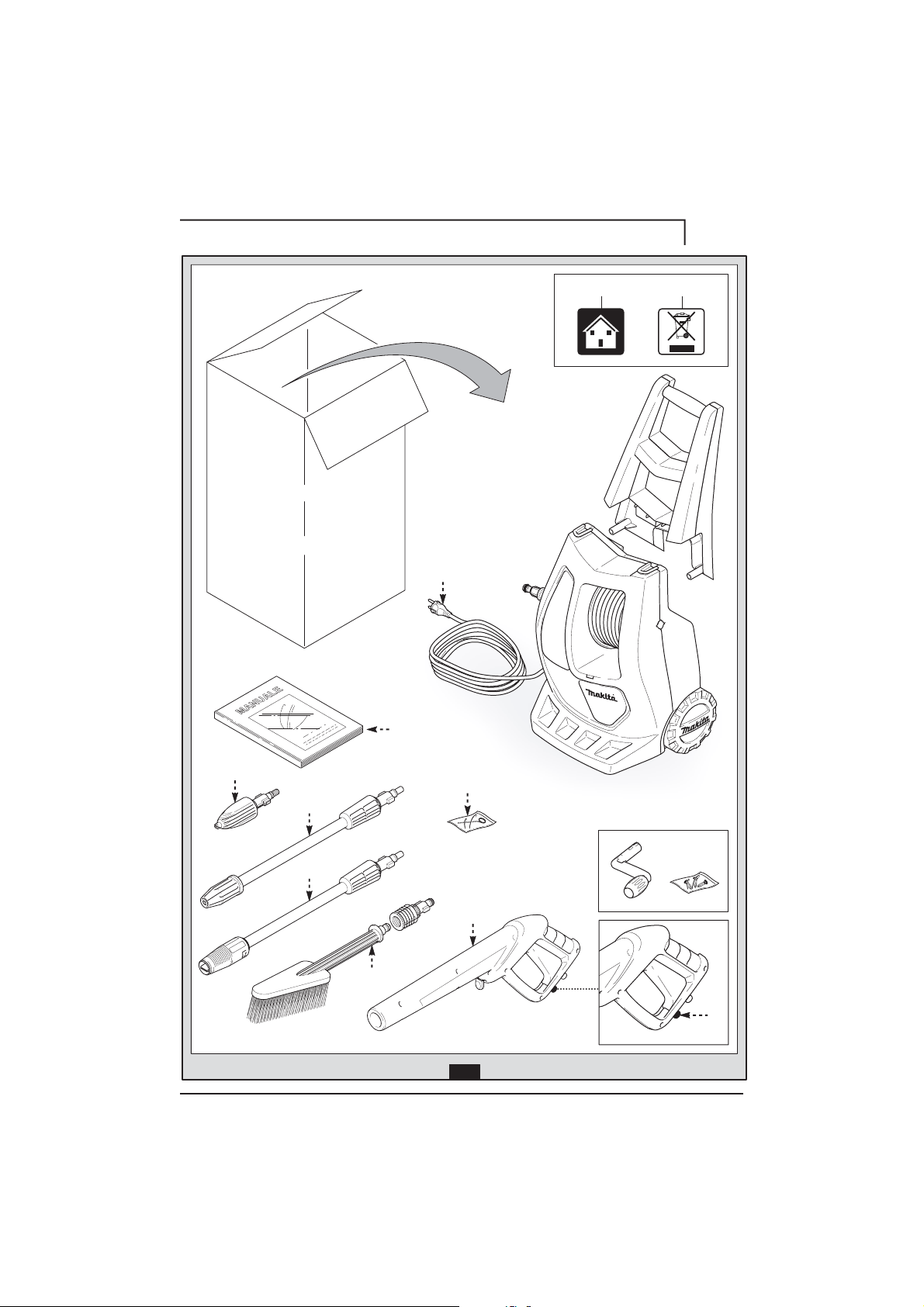
GENERAL INFORMATION FIG.1
3
3.1 Use of the manual
EN
This manual forms an integral part of the appliance and should be
kept for future reference. Please read it carefully before installing/
using the unit. If the appliance is sold, the Seller must pass on this
manual to the new owner along with the appliance.
3.2 Delivery
The appliance is delivered partially assembled in a cardboard box.
The supply package is illustrated in fig.1.
3.2.1 Documentation supplied with the appliance
3.3 Disposing of packaging
The packaging materials are not environmental pollutants but must
still be recycled or disposed of in compliance with the relevant
legislation in the country of use.
3.4 Safety signs
Comply with the instructions provided by the safety signs fitted to
the appliance.
Check that they are present and legible; otherwise, fit replacements
in the original positions.
E1 sign – Indicates that the appliance must not be disposed of as
municipal waste; it may be handed in to the dealer on purchase of a
new appliance. The appliance's electrical and electronic parts must
not be reused for improper uses since they contain substances
which constitute health hazards.
3.4.1 Symbols
TECHNICAL INFORMATION FIG.1
4
4.1 Envisaged use
This appliance has been designed for individual use for the cleaning
of vehicles, machines, boats, masonry, etc, to remove stubborn dirt
using clean water and biodegradable chemical detergents.
Vehicle engines may be washed only if the dirty water is disposed of
as per regulations in force.
- Intake water temperature: see data plate on the appliance.
- Intake water pressure: min. 0,1MPa-max 1MPa.
- Operating ambient temperature: above 0°C.
The appliance is compliant with the EN 60335-2-79/A1 standard.
4.2 Operator
The symbol on the front cover identifies the appliance’s intended
operator (professional or non-professional).
4.3 Improper use
Use by unskilled persons or those who have not read and understood the instructions in the manual is forbidden.
The introduction of inflammable, explosive and toxic liquids into the
appliance is prohibited.
Use of the appliance in a potentially inflammable or explosive
atmosphere is forbidden.
The use of non-original spare parts and any other spare parts not
specifically intended for the model in question is prohibited.
All modifications to the appliance are prohibited. Any modifications
made to the appliance shall render the Declaration of Conformity
null and void and relieve the manufacturer of all liability under civil
and criminal law.
A1 Use and maintenance manual
A2 Safety instructions
A3 Declaration of conformity
A4 Warranty regulations
E2 symbol – Indicates that the appliance is intended for professional use, i.e. for experienced people
informed about the relative technical, regulatory
and legislative aspects and capable of performing the
operations necessary for the use and maintenance of the
appliance.
E3 symbol – Indicates that the appliance is
intended for non-professional (domestic) use.
4.4 Main components
B1 Adjustable spray nozzle
B2 Lance
B3 Gun with safety catch
B4 Power supply cable with plug
B5 High pressure hose
B6 Detergent tank (on models with this feature)
4.4.1 Accessories (if included in the supply package – see fig.1).
C1 Nozzle cleaning tool
C2 Rotating nozzle kit
C3 Handle
C4 Brush
C5 Hose reel
4.5 Safety devices
Caution - Danger!
Do not tamper with or adjust the safety valve setting.
- Safety valve and/or pressure limiting valve.
The safety valve is also a pressure limiting valve.
When the gun trigger is released, the valve opens and the water
recirculates through the pump inlet or is discharged onto the
ground.
- Thermostat valve (D1 where fitted)
If the water temperature exceeds the temperature set by the
manufacturer, the thermostat valve discharges the hot water and
draws in an amount of cold water equal to the amount of water
discharged, until the correct temperature is restored.
- Safety catch (D): prevents accidental spraying of water.
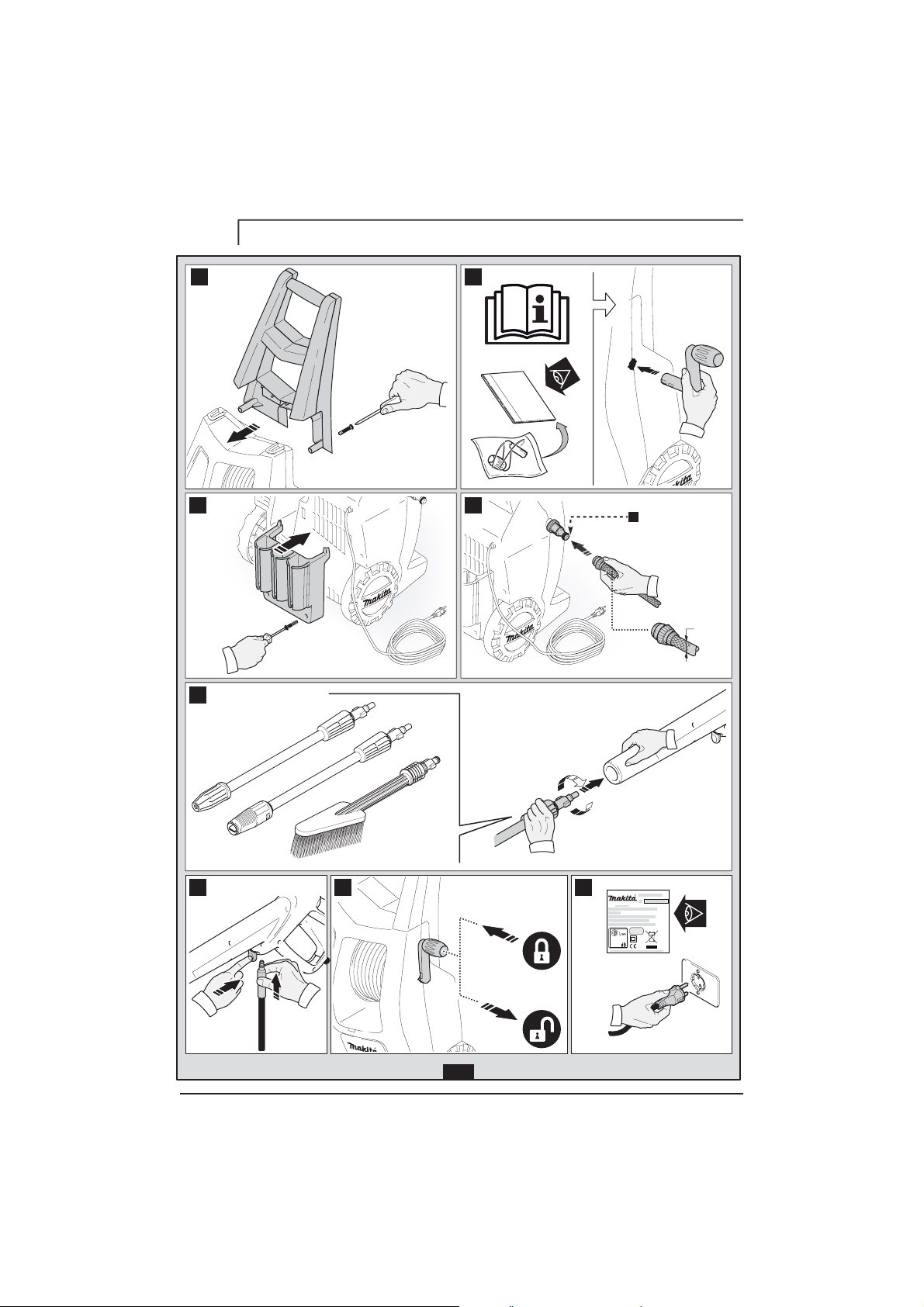
INSTALLATION FIG.2
5
5.1 Assembly
Caution - Danger!
All installation and assembly operations must be
performed with the appliance disconnected from the mains
power supply.
The assembly sequence is illustrated in fig.2.
5.2 Assembling the rotating nozzle
(For models with this feature)
The rotating nozzle kit delivers greater washing power.
Use of the rotating nozzle may cause of reduction in pressure of
25% compared to the pressure obtained with the adjustable nozzle.
However, the rotating nozzle kit delivers greater washing power due
to the rotation of the water jet.
5.3 Electrical connection
Caution - Danger!
Check that the electrical supply voltage and frequency (V-Hz) correspond to those specified on the appliance
data plate (fig.2). The appliance should only be connected
to a mains power supply equipped with an adequate earth
connection and a differential security breaker (30 mA) to cut
off the electricity supply in the instance of a shor t circuit.
5.3.1 Use of extension cables
Use cables featuring “IPX5” protection level.
The cross-section of the extension cable should be proportionate to its length; the longer it is, the greater its
cross-section should be. See table I.
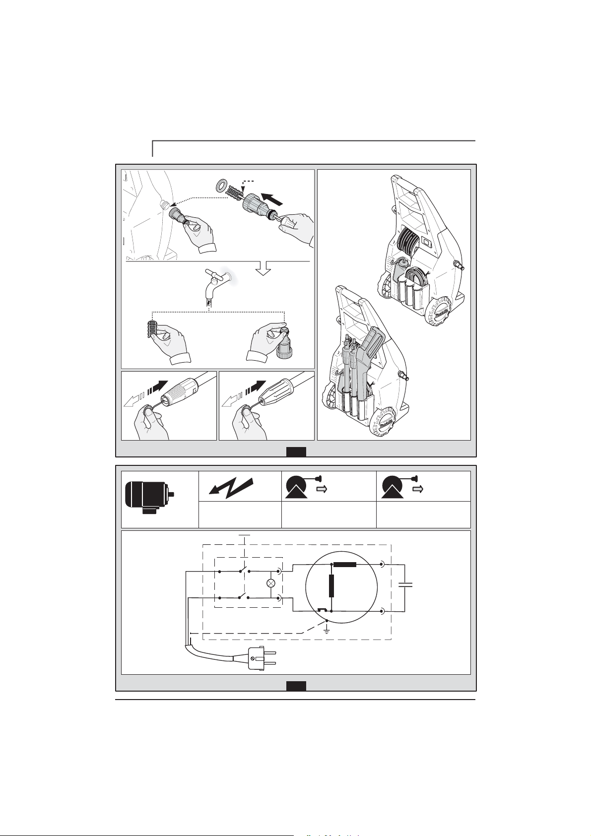
5.4 Water supply connection
Caution - Danger!
Only clean or filtered water should be used for intake.
The delivery of the water intake tap should be equal to that
of pump capacity.
Place the appliance as close to the water supply system as possible.
5.4.1 Connection points
●
Water outlet (OUTLET)
■
Water inlet with filter (INLET )
Page 9

5.4.2 Connection to the mains water supply
The appliance can be connected directly to the mains
drinking water supply only if the supply hose is fitted with
a backflow preventer valve as per current regulations in
force. Make sure that the hose is at least Ø 13 mm and
that it is reinforced.
ADJUSTMENT INFORMATION FIG.3
6
6.1 Adjusting the spray nozzle (for models with this feature)
Water flow is adjusted by regulating the nozzle (E).
6.2 Adjusting the detergent (on models with this feature)
Detergent flow is adjusted using the regulator (F).
6.3 Adjusting the detergent pressure
Set the adjustable nozzle (E) on " " to deliver detergent at the
correct pressure (on models with this feature).
6.4 Adjusting the pressure (on models with this feature)
The regulator (G) is used to adjust the working pressure. The pres-
sure is shown on the pressure gauge (where fitted).
INFORMATION ON USE OF THE APPLIANCE FIG.4
7
7.1 Controls
- Starter device (H).
Set the starter switch on (ON/1) to:
a) start the motor (in models without TSS device);
b) set the motor ready to start (in models with TSS device).
If there is a pilot light on the starter device, it should light up.
If the “low/high” settings are available, use them as follows:
Low : low pressure washing
High : high pressure washing
Set the starter device switch on (OFF/0) to shut down the appliance.
If there is a pilot light on the starter device, it should go out.
- Water jet control lever (I).
Caution - Danger!
During operation the appliance must be positioned
as shown in fig. 4 on a sturdy, stable surface.
7.2 Start-up
1) Turn on the water supply tap fully.
2) Release the safety catch (D).
3) Depress the gun trigger for a few seconds and start up the appliance using the starter device (ON/1).
Caution - Danger!
Before starting up the appliance check that the water
supply hose is connected properly; use of the appliance
without water will damage it; do not cover the ventilation
grilles when the appliance is in use.
TSS models - In TSS models with automatic delivery flow cut-off
system:
- when the gun trigger is released the dynamic pressure automati-
cally cuts out the motor (see fig.4);
- when the gun trigger is depressed the automatic drop in pres-
sure starts the motor and the pressure is restored after a very
slight delay;
- if the TSS is to function correctly all gun releasing and depress-
ing operations must be performed at intervals of less than 4-5
seconds.
On three-phase models for professional use, at first use start the
appliance for a very short time to check that the motor is running
in the correct direction. If the motor fan is turning anti-clockwise,
exchange two of the three phase wires (L1, L2, L3) in the electrical plug.
To prevent damage to the appliance, do not allow it to operate dry and when running do not stop the water jet for more
than 10 minutes at a time (for models without TSS device).
7.3 Stopping the appliance
1) Set the starter device switch on (OFF/0).
2) Depress the gun trigger and discharge the residual pressure
inside the hoses.
3) Engage the gun safety catch (D).
7.4 Restarting
1) Release the safety catch (D).
2) Depress the gun trigger and discharge the residual air inside
the hoses.
3) Set the starter device on (ON/1).
7.5 Storage
1) Switch the appliance off (OFF/0).
2) Remove the plug from the socket.
3) Turn off the water supply tap.
4) Discharge the residual pressure from the gun until all the water
has come out of the nozzle.
5) Drain and wash out the detergent tank at the end of the working session. To wash out the tank, use clean water instead of
the detergent.
6) Engage the gun safety catch (D).
7.6 Refilling and using detergent
When using detergent, the adjustable nozzle must be set on
" " (on models with this feature).
Use of a high pressure hose longer than the one originally supplied
with the cleaner, or the use of an additional hose extension, may
reduce or completely halt the intake of detergent.
Fill the ta nk wit h high ly degr adable deterge nt.
7.7 Recommended cleaning procedure
Dissolve dirt by applying the detergent mixed with water to the
surface while still dry.
When dealing with vertical surfaces work from the bottom upwards.
Leave the detergent to act for 1-2 minutes but do not allow the
surface to dry. Starting from the bottom, use the high pressure jet
at a minimum distance of 30 cm. Do not allow the rinse water to run
onto unwashed surfaces.
In some cases, scrubbing with brushes is needed to remove dirt.
High pressure is not always the best solution for good washing
results, since it may damage some surfaces. The finest adjustable
nozzle jet setting or the rotating nozzle should not be used on
delicate or painted parts, or on pressurised components (e.g tyres,
inflation valves, etc.).
Effective washing depends on both the pressure and volume of the
water used, to the same degree.
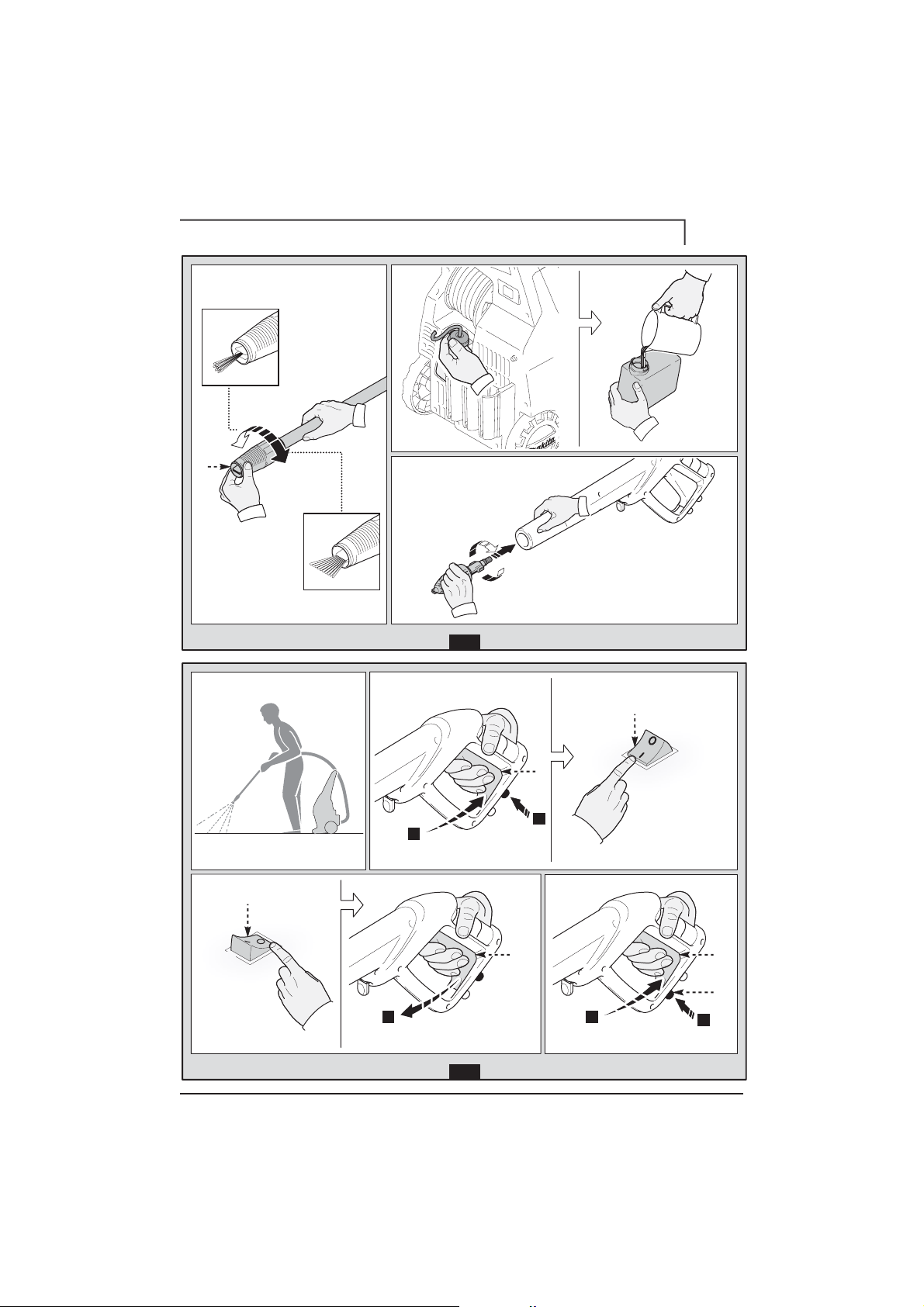
MAINTENANCE FIG.5
8
Any maintenance operations not covered by this chapter should be
carried out by an Authorized Sales and Service Centre.
Caution - Danger!
Always disconnect the plug from the power socket
before carrying out any work on the appliance.
8.1 Cleaning the nozzle
1) Disconnect the lance from the nozzle.
2)
R e m o v e a n y d i r t d e p o s i t s f r o m t h e n o z z l e h o l e u s i n g t h e t o o l ( C1).
8.2 Cleaning the filter
Inspect the intake filter (L) and detergent filter (if fitted) before each
use, and clean in accordance with the instructions if necessary.
8.3 Unjamming the motor (on models with this feature)
In case of lengthy stoppages, limescale sediments may cause the
motor to seize. To unjam the motor, turn the drive shaft with a
tool (M).
8.4 End-of-season storage
Treat the appliance with non-corrosive, non-toxic antifreeze before
storing it away for winter.
Put the appliance in a dry place, protected from frost.
9English
EN
Page 10

10 English
TROUBLESHOOTING
9
EN
Problem Possible causes Remedy
Nozzle worn Replace nozzle
Water filter fouled Clean filter (fig.5)
Water supply pressure low Turn on water supply tap fully
Pump does not reach working
pressure
Air being sucked into system Check tightness of hose fittings
Switch off the appliance and keep depressing and releas-
Air in pump
ing the gun trigger until the water comes out in a steady
flow. Switch the appliance back on again.
Adjustable nozzle not positioned correctly Turn the adjustable nozzle (E) (+) (fig.3)
Thermostatic valve tripped Wait for correct water temperature to be restored
Water intake from external tank Connect appliance to the mains water supply
Pressure drops during use
Intake water too hot Reduce temperature
Nozzle clogged Clean nozzle (fig.5)
Intake filter (L) dirty Clean filter (L) (fig.5)
Check that the voltage of the mains power supply line is
the same as that on the plate (fig.2)
Motor “sounds” but fails to start
Insufficient power supply
Voltage loss due to use of extension cable Check characteristics of extension cable
Appliance not used for a long period of time Contact your nearest Authorized Service Centre
Problems with TSS device Contact your nearest Authorized Service Centre
Check that the plug is firmly in the socket and that the
mains voltage supply is present (*)
Using the tool (L) unjam the motor from the hole at the
rear of the appliance (in models with this feature) (fig.5)
Have the seals replaced at your nearest Authorized
Service Centre
Motor fails to start
Water leakage
No electrical power
Problems with TSS device Contact your nearest Authorized Service Centre
Appliance not used for a long period of time
Seals worn
Safety valve tripped and discharging Contact an Authorized Service Centre
Appliance noisy Water too hot Reduce temperature (see technical data
Oil leakage Seals worn Contact your nearest Authorized Service Centre
TSS versions only: motor starts
even with gun trigger is released
Nozzle clogged Clean nozzle (fig.5)
High pressure system or pump hydraulic circuit not
watertight
Contact your nearest Authorized Service Centre
TSS versions only: no water delivery when gun trigger is depressed
Nozzle clogged Clean nozzle (fig.5)
(with supply hose connected)
Adjustable nozzle on high pressure setting
Set nozzle on "
" setting (fig.5)
Detergent too dense Dilute with water
No detergent taken in
High pressure hose extension being used Fit original hose
Deposits or restriction in detergent circuit
Flush with clean water and eliminate any restrictions. If the
problem persists, contact an Authorized Service Centre
(*) If the motor starts and does not restart during operation, wait 2-3 minutes before repeating the start-up procedure (overload cutout has been tripped).
If the problem recurs more than once, contact your nearest Authorized Service Centre.
DECLARATION OF CONFORMITY
We declare under our sole responsibility that this
product is in conformity with the following
standards or standardized documents
EN 60335-1 - EN 60335-2-79; EN 55014-1; EN 55014-2;
EN 61000-3-2;EN 61000-3-3; EN 61000-3-11; EN 60704-1
In accordance with the regulations:
2006/95/CE, 2002/95/CE, 2002/96/CE, 2004/108/CE, 2000/14/CE
Name and address of the person responsible for issue of
Date: 29.12.2009
MODENA (I)
Stefano Reverberi
Managing Director
2006/42/CE
the technical dossier:
Stefano Reverberi / AR Managing Director
Via ML King, 3 - 411 22 Moden a, Ital y
EN
MODEL SERIAL NUMBER
Page 11

Technical Data (EN) Unit
Output
Pressure
Maximum pressure
Power
T° input
Maximum input pressure
Repulsive force of the gun to the maximum pressure
Motor Insulation
Motor Protection
Voltage
Sound level
K = 3 dB(A) :
LPA (EN 60704-1)
LWA (EN 60704-1)
Unit vibrations
Weig ht
K = 1,5
M/s
2
:
HW121
6,5
L/min
11
MPa
13
MPa
1,8
kW
50
°C
1
MPa
14,95
N
Class F
-
IPX5
-
230/50
V/Hz
dB (A) 83,1
dB (A) 91
2
3,72
M/s
17,8
kg
MODEL SERIAL NUMBER
Makita Corporation - Japan
EN EC Declaration of conformity
We Makita Corporation, Anjo, Aichi, Japan declare that the following Makita Machine(s):
Designation of Machine High Pressure Washer
Model No / Type HW121
Input power 1,8 kW
Conforms to the following European Directives:
2006/42/EC, 2006/95/EC, 2002/95/EC, 2002/96/EC, 2004/108/EC, 2000/14/EC
And are manufactured in accordance to the following standards or standardised
documents: EN 60335-1; EN 60335-2-79; EN 55014-1; EN 55014-2; EN 61000-3-2; EN 610003-3; EN 61000-3-11; EN 60704-1
The Technical Documentation is kept by our authorised Representative in Europe who is:
Makita International Europe Ltd,
Michigan, Drive, Tongwell,
Milton Keynes, MK15 8JD, England
The conformity assessment procedure required by Directive 2000/14/EC was in
accordance with annex V
Measured Sound Power Level L
Guaranteed Sound Power Level L
90
: 83,1 dB (A); (K=3 dB(A)))
PA
: 91 dB (A); (K=3 dB(A)))
WA
06th December 2010
Mr Tomoyasu Kato
Director
Makita Corporation, 3-11-8 Sumiyoshi-Cho, Anjo, Aichi, 446-8502, Japan
Page 12

12 Deutsch
SICHERHEITSANWEISUNGEN
1
1.1 Bei dem von Ihnen erworbenen Produkt handelt es sich um
ein hochtechnisiertes Gerät eines der europaweit erfahrensten
Hersteller von Hochdruckpumpen. Die optimale Nutzung der
Geräteleistungen setzt die Kenntnis und Befolgung der nachstehenden Anleitungen voraus. Wir beglückwünschen Sie zu Ihrer
Wahl und wünschen Ihnen viel Erfolg bei der Arbeit mit Ihrem
Gerät.
SICHERHEITSVORSCHRIFTEN/RESTGEFAHREN
2
2.1 WARNHINWEISE: UNZULÄSSIG
2.1.1
mit solchen Flüssigkeiten einsetzen, die den vorschriftsmäßigen
Betrieb des Geräts beeinträchtigen könnten. E
VERGIFTUNGSGEFAHR
2.1.2
2.1.3
S
TROMSCHLAGGEFAHR
2.1.4
2.1.5
2.1.6
2.1.7
2.1.8
2.1.9
2.1.10
hiervon sofort unterrichten. Geräte ohne Typenschild dürfen AUF
KEINEN FALL eingesetzt werden, da sie potentielle Gefahrenquellen
darstellen. H
2.1.11
ihre Einstellung NICHT verändern. B
2.1.12
2.1.13
!
Wasserstrahl NIEMALS auf Personen oder Tiere
richten. V
Wasserstra hl NIEMALS auf das Gerät, auf
Elektroteile bzw. andere Elektrogeräte richten.
!
Gerät AUF KEINEN FALL bei Regen im Freien verwenden.
K
URZSCHLUSSGEFAHR
Gerät AUF KEINEN FALL durch Kinder oder Unbefugte
anwenden lassen. V
Stecker bzw. Steckdose N IEMALS mit nassen
Händen anfassen. S
Gerät NIEMALS mit beschädigtem Stromkabel
betreiben. S
Gerät NIEMALS mit beschädigtem
Hochdruckschlauch betreiben. B
Hebel der Pistole NIEMALS auf Betriebsstellung sperren.
V
ERLETZUNGSGEFAHR
Auf dem Gerät muss das Typenschild mit den spezifischen
Eigenschaften angebracht sein, anderenfalls den Händler
IERBEI BESTEHT UNFALLGEFAHR
KEINE unbefugten Eingriffe am Steuerventil und
an den Sicherheitsvorrichtungen vornehmen und
Originaldurchmesser des Strahlkopfs AUF KEINEN FALL
ändern. G
EFAHR DURCH VERÄNDERTE EIGENSCHAFTEN
Gerät NIEMALS ohne Aufsicht belassen. U
Gerät AUF KEI NEN FALL mit
entzü ndbaren, giftigen bzw.
XPLOSIONS-ODER
ERLETZUNGSGEFAHR
!
!
ERLETZUNGSGEFAHR
TROMSCHLAG-UND KURZSCHLUSSGEFAHR
!
TROMSCHLAGGEFAHR
!
ERSTGEFAHR
!
!
ERSTGEFAHR
!
!
NFALLGEFAHR
!
!
!
2.2.2
S
TROMSCHLAGGEFAHR
• Der Betrieb mit einem Fehlerstromschalter (30 mA) bietet
zusätzliche persönliche Sicherheit.
Bei den Modellen ohne Stecker muss die Installation von einem
Fachmann ausgeführt werden.
Ausschließlich vorschriftsmäßige Verlängerungskabel mit einem
angemessenen Querschnitt verwenden.
Das Gerät ausschließlich an eine geeignete und
vorschriftsmäßige Stromquelle ANSCHLIESSEN.
!
2.2.3
Durch den hohen Druck können Teile zurückprallen. Daher
muss die Bedienungsperson die zu ihrem Schutz er forderliche
Schutzkleidung und Schutzausrüstung tragen. V
2.2.4
2.2.5
2.2.6
2.2.7
2.2.8
2.2.9
2.2.10
2.2.11
Vor jeglichen Arbeiten am Gerät unbedingt den Stecker
HERAUSZIEHEN. A
!
ANLASSENS
Pistole bei Betätigung des Hebels wegen dem
druckbedingten Rückstoß sicher FESTHALTE N.
V
ERLETZUNGSGEFAHR
Gemäß EN 12729 (BA) ist der direkte Anschluss des Geräts an die
Trinkwasserleitung nur dann möglich, wenn in der Zufuhrleitung
eine Schutzvorrichtung gegen Rückfluss mit Ablauf installiert ist.
G
EFAHR DER WASSERVERSCHMUTZUNG
Die Wartung bzw. Reparatur von elektrischen
Bauteilen DARF NUR durch Fachpersonal erfolgen.
V
ERLETZUNGSGEFAHR
Vor Abtrennen des Schlauchs vom Gerät unbedingt den
Restdruck ABLASSEN. V
Vor dem Gebrauch sowie in regelmäßigen Abständen die
Arretierung der Schraubteile KONTROLLIEREN und die
Komponenten des Geräts auf Bruch bzw. Verschleiß überprüfen.
U
NFALLGEFAHR
!
Stromkabel verträgliche Reinigungsmittel VERWENDEN. B
STROMSCHLAGGEFAHR
Gerät aufhalten. V
NSONSTEN BESTEHT GEFAHR UNBEABSICHTIGTEN
!
Vo rs ch ri ft en de s ö rt li ch en
Wasserve rsorgungsunternehmens BEFOLG EN.
!
!
ERLETZUNGSGEFAHR
Aus schl ießl ich mit der
Ummantelung von Gerät und
!
Personen und Tiere s ollen sich in eine m
Sicherheitsabstand von mindestens 15 m vom
ERLETZUNGSGEFAHR
!
ERLETZUNGSGEFAHR
!
!
ERST-UND
2.1.14
2.1.15
2.1.16
2.1.17
Gerät NICHT am STROMKABEL ziehen. K
Verhindern, dass Fahrzeuge über den Hochdruckschlauch fahren.
Gerät nicht am Hochdruckschlauch ziehen. B
Es kann gefährlich sein, den Hochdruckstrahl auf Reifen,
Reifenventile und sonstige unter Druck stehende Bauteile zu
richten. Nicht den Drehdüsen-Satz verwenden und in jedem
Fall den Wasserstrahl beim Reinigen auf einem Abstand von
mindestens 30 cm halten. B
ERSTGEFAHR
ERSTGEFAHR
!
2.2 WARNHINWEISE: ERFORDERLICH
2.2.1
Sämtliche stromf ührenden Teile MÜ SSEN gegen
Wass erstra hlen GES CHÜTZT SEIN. K
URZSCHLUSSGEFAHR
URZSCHLUSSGEFAHR
!
!
!
Page 13

ALLGEMEINE INFORMATIONEN ABB. 1
3
3.1 Gebrauch des Handbuchs
Dieses Handbuch ist Bestandteil des Geräts. Es muss sorgfältig aufbewahrt werden, damit es auch künftig zu Rate gezogen werden kann. Das
Handbuch vor Installation/Gebrauch aufmerksam lesen. Der Eigentümer
ist verpflichtet, das Handbuch im Falle der Veräußerung des Geräts dem
neuen Eigentümer zu übergeben.
3.2 Lieferung
Das Gerät wird teilweise zerlegt in einen Karton verpackt geliefert.
Der Lieferumfang ist in Abb. 1 dargestellt.
3.2.1 Mitgelieferte Dokumentation
A1 Gebrauchs- und Wartungsanleitung
A2 Sicherheitsanweisungen
A3 Konformitätserklärung
3.3 Entsorgung der Verpackung
3.4 Informationszeichen
4
4.1 Vorgesehener Gebrauch
4.2 Bedienungsperson
4.3 Unzulässiger Gebrauch
A4 Garantiebedingungen
Die Verpackungsmaterialien sind nicht umweltschädlich, müssen jedoch
in jedem Fall in Einklang mit den im Bestimmungsland geltenden
Bestimmungen entsorgt bzw. wiederverwertet werden.
Die Informationen beachten, die die am Gerät angebrachten Schilder
enthalten.
Sollten sich die Schilder gelöst haben oder unleserlich geworden sein,
sind sie durch neue Schilder zu ersetzen, die an den ursprünglichen
Stellen angebracht werden müssen.
Schild E1 - Es verbietet die Entsorgung des Geräts als normaler Abfall.
Er kann beim Kauf eines neuen Geräts dem Händler übergeben werden.
Die elektrischen und elektronischen Komponenten des Geräts dürfen
nicht zweckwidrig wiederverwendet werden, da sie gesundheitsschädliche Stoffe enthalten.
3.4.1 Symbole
Symbol E2 - Es weist darauf hin, dass das Gerät für
den gewerblichen Gebrauch bestimmt ist, d.h. für
den Gebrauch durch Personen, die über die hierzu
erforderliche Erfahrung und die nötigen technischen
Kenntnisse verfügen, die gesetzlichen Bestimmungen kennen
und in der Lage sind, die zum Betrieb und zur Wartung des
Geräts erforderlichen Tätigkeiten auszuführen.
Symbol E3 - Es weist darauf hin, dass das Gerät für den
nichtgewerblichen (privaten) Gebrauch bestimmt ist.
TECHNISCHE INFORMATIONEN ABB. 1
Das Gerät ist zum individuellen Gebrauch zum Reinigen von Fahrzeugen,
Maschinen, Booten, Mauer werken usw. bestimmt, um hartnäckige
Verschmutzungen mit sauberem Wasser und biologisch abbaubaren
chemischen Renigungsmitteln zu entfernen.
Das Waschen von Fahrzeugmotoren ist nur dann erlaubt, wenn das
Abwasser vorschriftsmäßig entsorgt wird.
- Wasserzulauftemperatur: Siehe Typenschild am Gerät.
- Wasserzulaufdruck: min. 0,1 MPa - max.1 MPa.
- Betriebsumgebungstemperatur: Über 0°C.
Das Gerät entspricht der europäischen Norm EN 60335-2-79/A1 (siehe
Symbol E3).
Das Symbol auf dem Deckblatt gibt an, von welchen Personen das Gerät
bedient werden darf (gewerblicher oder privater Gebrauch).
Der Gebrauch durch unerfahrene Personen oder durch Personen, die die
in der Gebrauchsanleitung enthaltenen Anweisungen nicht gelesen und
vollständig verstanden haben, ist verboten.
Es ist verboten, das Gerät mit entzündlichen, explosiven oder giftigen
Flüssigkeiten zu speisen.
Es ist verboten, das Gerät in entzündlicher oder explosiver Atmosphäre
zu betreiben.
Es ist verboten, anderes als das für das jeweilige Modell bestimmte
Originalzubehör zu verwenden.
Es ist verboten, am Gerät Änderungen vorzunehmen. Unbefugte
Änderungen führen zum Erlöschen der Konformitätserklärung und befreien den Hersteller von jeder zivil- und strafrechtlichen Verantwortung.
4.4 Wichtigste Teile
B1 Einstellbarer Düsenkopf
B2 Lanze
B3 Pistole mit Sicherung
B4 Netzkabel mit Stecker
B5 Hochdruckschlauch
B6 Reinigungsmitteltank (wo vorgesehen)
4.4.1 Zubehör (falls im Lieferumfang eingeschlossen - siehe Abb. 1).
C1 Reinigungswerkzeug für Düsenkopf
C2 Satz Drehdüse
C3 Griff
C4 Bürste
C5 Schlauchhaspel
4.5 Sicherheitsvorrichtungen
Achtung - Gefahr!
Keine unbefugten Änderungen am Sicherheitsventil vor-
nehmen und seine Einstellung nicht verändern.
- Sicherheits- und/oder Druckbegrenzungsventil.
Das Sicherheitsventil ist auch ein Druckbegrenzungsventil. Beim
Schließen der Pistole öffnet sich das Ventil und das Wasser läuft zurück
zur Saugseite der Pumpe oder wird auf den Boden abgelassen.
- Thermostatventil (D1 falls vorgesehen)
Wenn die Wassertemperatur die vom Hersteller vorgesehene Temperatur
überschreitet, lässt das Thermostatventil das heiße Wasser ab und saugt
eine der Menge des abgelassenen Wassers entsprechende Menge kalten
Wass ers a n, u m wie der d ie r ichti ge Tempe ratur herz ustel len.
- Sicherung (D): Sie verhindert die ungewollte Betätigung des
Abzugshebels.
INSTALLATION ABB. 2
5
5.1 Montage
Achtung - Gefahr!
Das Gerät muss bei der Ausführung aller Installations- und
Montagearbeiten vom Stromnetz getrennt sein.
Für die Reihenfolge der Montagearbeiten siehe Abb. 2.
5.2 Montage der Drehdüse
(wo vorgesehen)
Der Drehdüsen-Satz erlaubt die Erhöhung der Arbeitsleistung.
Bei Verwendung der Drehdüse kann es zu einer Abnahme des Drucks um
25 % gegenüber dem Druck kommen, den man mit dem einstellbaren
Düsenkopf erhält. Da sie jedoch das Wasser in Drehung versetzt, erhält
man mit ihr eine höhere Waschleistung.
5.3 Elektrischer Anschluss
Achtung - Gefahr!
Sicherstellen, dass Netzspannung und -frequenz den
Angaben auf dem Typenschild (V-Hz) entsprechen (Abb. 2). Das
Gerät an ein Stromnetz mit wirksamer Erdung anschließen, das über
einen Fehlerstromschutz (30 mA) verfügt, der die Stromversorgung
im Falle eines Kurzschlusses unterbricht.
5.3.1 Gebrauch eines Verlängerungskabels
Kabel mit Schutzart „IPX5“ verwenden.
Der Querschnitt des Verlängerungskabels muss proportional
zu seiner Länge sein. Je länger es ist, um so größer muss der
Querschnitt sein. Siehe Tabelle I.
5.4 Wasseranschluss
Achtung - Gefahr!
Nur gefiltertes oder sauberes Wasser ansaugen. Der
Wasserhahn muss mindestens eine der Förderleistung der Pumpe
entsprechende Wassermenge liefern.
Das Gerät so nahe wie möglich am Wassernetzanschluss aufstellen.
13Deutsch
DE
Page 14

14 Deutsch
5.4.1 Anschlussstutzen
● Wasserauslass (OUTLET)
■ Wassereinlauf mit Filter (INLET )
5.4.2 Anschluss an die Wasserleitung
Der direkte Anschluss des Geräts an die Trinkwasserleitung ist
DE
6
6.1 Einstellung des Düsenkopfs (wo vorgesehen)
6.2 Einstellung der Reinigungsmittelmenge (wo vorgesehen)
6.3 Einstellung der Reinigungsmittelabgabe
6.4 Einstellung des Drucks (wo vorgesehen)
7
7.1 Bedieneinrichtungen
7.2 Inbetriebnahme
nur dann zulässig, wenn in der Zuleitung eine vorschriftsmäßige Schutzvorrichtung gegen Rückfluss mit Ablauf installiert ist.
Der Schlauchdurchmesser muss mindestens 13 mm betragen;
der Schlauch selbst muss verstärkt sein.
EINSTELLUNGEN ABB. 3
Den Wasserstrahl am Düsenkopf (E) regulieren.
Die abzugebende Reinigungsmittelmenge mit dem Regler (F) dosieren.
Den einstellbaren Düsenkopf
Reinigungsmittel mit dem richtigen Druck abgegeben wird (wo vorgesehen).
Den Arbeitsdruck mit Regler (G) regulieren. Der Druck wird auf dem
Manometer angezeigt (falls vorhanden).
(E)
in die Stellung „ “ bringen, damit das
INFORMATIONEN ZUM GEBRAUCH ABB. 4
- Einschalteinrichtung (H).
Die Einschalteinrichtung auf (ON/1) schalten, um:
a) den Motor zu starten (bei den Modellen ohne TSS-Vorrichtung).
b) den Motor für den Betrieb vorzubereiten (bei den Modellen mit
TSS-Vorrichtung).
Wenn die Einschalteinrichtung über eine Kontrolllampe verfügt, muss
diese Kontrolllampe dann leuchten.
Die Schaltstellungen „low/high“, die ggf. vorgesehen sind, stehen für:
Low : Waschen mit Niederdruck.
High : Waschen mit Hochdruck.
Die Einschalteinrichtung auf (OFF/0) schalten, um den Betrieb des Geräts
zu beenden.
Wenn die Einschalteinrichtung über eine Kontrolllampe verfügt, muss
diese Kontrolllampe dann erlöschen.
- Abzugshebel Wasserstrahl (I).
Achtung - Gefahr!
Das Gerät muss für den Betrieb wie in Abb. 4 angegeben auf
einem sicheren und festen Untergrund aufgestellt werden.
1) Den Wasserhahn ganz öffnen.
2) Die Sicherung (D) lösen.
3) Die Pistole einige Sekunden geöffnet lassen und das Gerät mit der
Einschalteinrichtung einschalten (ON/1).
Achtung - Gefahr!
Vor der Inbetriebnahme des Geräts sicherstellen, dass er
richtig mit Wasser gespeist wird. Wenn er trocken läuft, kann er
Schaden nehmen. Während des Betriebs darauf achten, dass die
Lüftungsgitter nicht bedeckt sind.
TSS-Modelle - Bei den TSS-Mod ellen mit au tomatischer
Zulaufunterbrechung:
- Beim Schließen der Pistole schaltet der dynamische Druck automa-
tisch den Elektromotor aus.
- Beim Öffnen der Pistole startet der Druckabfall automatisch den Motor.
Der Druck wird mit einer minimalen Verzögerung wiederhergestellt.
- Für den korrekten Betrieb der TSS-Vorrichtung muss man zwischen
dem Schließen und dem erneuten Öffnen der Pistole mindestens
4 - 5 Sekunden abwarten.
Die dreiphasigen Modelle für den gewerblichen Gebrauch muss
man bei der ersten Inbetriebnahme kurz anlaufen lassen, um die
Drehrichtung des Motors zu kontrollieren. Wenn sich der Lüfter des
Motors entgegen dem Uhrzeigersinn dreht, muss man zwei der drei
Phasen (L1, L2, L3) im Netzstecker vertauschen.
Um Schäden am Gerät zu vermeiden, darf man es nicht trocken laufen lassen oder den Wasserstrahl bei eingeschaltetem Gerät länger
als 10 Minuten unterbrechen (bei Modellen ohne TSS-Vorrichtung).
7.3 Ausschalten
1) Die Einschalteinrichtung auf (OFF/0) schalten.
2) Die Pistole betätigen, um den Druck aus den Leitungen abzulassen.
3) Die Sicherung (D) einklinken.
7.4 Erneuter Start
1) Die Sicherung (D) lösen.
2) Die Pistole betätigen, um den Druck aus den Leitungen abzulassen.
3) Die Einschalteinrichtung auf (ON/1) schalten.
7.5 Außerbetriebnahme
1) Das Gerät ausschalten (OFF/0).
2) Den Netzstecker aus der Steckdose ziehen.
3) Den Wasserhahn schließen.
4) Den Restdruck über die Pistole ablassen, bis das gesamte Wasser aus
dem Düsenkopf ausgetreten ist.
5) Nach der Arbeit den Reinigungsmitteltank entleeren und
waschen. Zum Waschen des Tanks sauberes Wasser anstelle des
Reinigungsmittels verwenden.
6) Die Sicherung (D) der Pistole wieder einklinken.
7.6 Einfüllen und Gebrauch des Reinigungsmittels
IFür die Abgabe des Reinigungsmittels muss sich entweder der einstellbare Düsenkopf in der Stellung „
Verwendet man einen längeren als den zur Originalausstattung
des Hochdruckreinigers gehörenden Hochdruckschlauch oder eine
zusätzliche Schlauchverlängerung, wird unter Umständen weniger oder
gar kein Reinigungsmittel angesaugt.
7.7 Ratschläge zum richtigen Gebrauch
Zum Lösen des Schmutzes das Reinigungsmittel zum Wasser gemischt
auf die noch trockenen Oberflächen sprühen.
Senkrechte Flächen von unten nach oben bearbeiten. Das Reinigungsmittel
1 bis 2 Minuten einwirken, die Oberfläche jedoch nicht trocknen lassen.
Dann die Oberflächen mit dem Hochdruckstrahl mit einem Abstand
von mindestens 30 cm von unten nach oben waschen. Die ausgespülte
Flüssigkeit darf nicht auf ungereinigten Flächen ablaufen.
Manchmal kann der Schmutz nur durch die mechanische Einwirkung der
Waschbürsten entfernt werden.
Der Hochdruck ist nicht immer die beste Lösung beim Waschen, da manche Oberflächen durch ihn Schaden nehmen können. Es empfiehlt sich,
für empfindliche, lackierte oder unter Druck stehende Teile (z.B. Reifen,
Reifenfüllventile usw.) den Nadelstrahl des einstellbaren Düsenkopfs
und den Drehdüse zu verwenden.
Eine gute Reinigungswirkung hängt in gleichem Maße vom Druck und
vom Wasservolumen ab.
WARTUNG ABB. 5
8
Alle nicht in diesem Kapitel genannten Wartungsarbeiten müssen von
einem autorisierten Kundendienstzentrum ausgeführt werden.
Achtung - Gefahr!
Vor der Ausführung von Eingriffen am Gerät unbedingt den
Netzstecker aus der Steckdose ziehen.
8.1 Reinigung des Düsenkopfs
1) Die Lanze von der Pistole lösen.
2) Mit dem Werkzeug (C1) die Bohrung des Düsenkopfs säubern.
8.2 Reinigung des Filters
Vor jedem Gebrauch den Saugfilter (L) und den Reinigungsmittelfilter (falls
vorgesehen) kontrollieren und erforderlichenfalls wie angegeben reinigen.
8.3 Aufheben einer Motorblockierung (wo vorgesehen)
Wenn das Gerät über lange Zeit nicht verwendet wird, können
Kalkablagerungen dazu führen, dass der Motor blockiert. Zum Aufheben
der Blockierung des Motors die Motorwelle mit dem Werkzeug (M) drehen.
8.4 Stilllegung und Lagerung
Vor Stilllegung und Lagerung über die kalte Jahreszeit das Gerät mit
einem milden und ungiftigen Frostschutzmittel betreiben.
Das Gerät an einem trockenen und frostgeschützten Ort aufbewahren.
“ (wo vorgesehen).
Page 15

INFORMATIONEN ZU BETRIEBSSTÖRUNGEN
9
Fehlfunktionen Wahrscheinliche Ursachen Abhilfe
Düse abgenutzt Düse ersetzen
Wasserfilter verschmutzt Filter reinigen (Abb. 5)
Wasserzulauf ungenügend Wasserhahn ganz öffnen
Pumpe erreicht vorgeschriebenen
Druck nicht
Es wird Luft angesaugt Anschlüsse überprüfen
Luft in der Pumpe
Gerät abschalten und Pistole betätigen, bis ein kontinuierlicher
Wasserstrahl austritt. Wieder einschalten
Düsenkopf nicht richtig eingestellt Den Düsenkopf (E) drehen (+) (Abb. 3)
Auslösung des Thermostatventils Abwarten , bis wieder die richtige Wassertemperatu r erreicht wurd e
Von externem Tank wird Wasser angesaugt Gerät an Wasserleitung anschließen
Druckschwankungen der Pumpe
Zulaufwassertemperatur zu hoch Temperatur senken
Düse verstopft Düse reinigen (Abb. 5)
Saugfilter (L) verschmutzt Filter (L) reinigen (Abb. 5)
Kontrollieren, ob die Netzspannung der auf dem Typenschild
angegebenen Bemessungsspannung entspricht (Abb. 2)
Der Motor „brummt“, läuft aber nicht an
Netzspannung zu niedrig
Spannungsfall durch die Verlängerung Eigenschaften der Verlängerung überprüfen
Langzeitige Abschaltung des Geräts Den Kundendienst kontaktieren
Probleme bei der TSS-Vorrichtung Den Kundendienst kontaktieren
Kontrollieren, ob die Netzspannung vorhanden und ob der
Netzstecker richtig in die Steckdose eingesteckt ist (*)
Über die rückseitige Öffnung die Blockierung des Motors mit dem
Werkzeug (L) aufheben (bei den Modellen, wo dies vorgesehen
Der Elektromotor läuft nicht an
Versorgungsspannung fehlt
Probleme bei der TSS-Vorrichtung Den Kundendienst kontaktieren
Gerät steht seit langer Zeit still
ist) (Abb. 5)
Wass erleck
Die Dichtungen sind abgenutzt
Die Dichtungen von einem autorisierten Kundendienstzentrum
ersetzen lassen
Auslösung des frei abblasenden Sicherheitsventils Den Kundendienst kontaktieren
Geräuschvoller Betrieb Wassertemperatur zu hoch Temperatur senken (siehe die Technischen Daten)
Ölleck Die Dichtungen sind abgenutzt Den Kundendienst kontaktieren
Nur für TSS: Das Gerät startet, obwohl
die Pistole nicht betätigt wird
Düse verstopft Düse reinigen (Abb. 5)
Dichtung im Hochdrucksystem oder im Pumpenkreislauf defekt Den Kundendienst kontaktieren
Nur für TSS: Bei Betätigung des
Abzugshebels der Pistole tritt kein
Wasser aus (bei angeschlossenem
Düse verstopft Düse reinigen (Abb. 5)
Zulaufschlauch)
Der einstellbare Düsenkopf ist auf Hochdruck eingestellt
Den Düsenkopf auf
„ “
einstellen (Abb. 3)
Reinigungsmittel zu zähflüssig Mit Wasser verdünnen
Es wird kein Reinigungsmittel angesaugt
Verwendung von Verlängerungen für den Hochdruckschlauch Nur den Originalschlauch verwenden
Mit sauberem Wasser reinigen und darauf achten, dass die Leitung
Reinigungsmittelleitung verkrustet oder gequetscht
nicht gequetscht wird. Wenn sich das Problem nicht beheben lässt,
den Kundendienst kontaktieren.
(*) Sollte der Motor während des Betriebs anhalten und nicht wieder anlaufen, vor dem erneuten Start 2 bis 3 Minuten abwarten (Auslös ung des Ü bertemperat urschutzes).
Fall s d ie Stö rung wi ede rhol t a uft ritt , d en Te chni sch en Kund end iens t k ont akti ere n.
KONFORMITÄTSERKLÄRUNG
Wir erklären in alleiniger Verantwortung,
dass das Produkt den folgenden Normen
und normativen Dokumenten entspricht:
EN 60335-1 - EN 60335-2-79; EN 55014-1; EN 55014-2;
EN 61000-3-2;EN 61000-3-3; EN 61000-3-11; EN 60704-1
gemäß den Bestimmungen der Richtlinien:
2006/95/EG, 2002/95/EG, 2002/96/EG, 2004/108/EG, 2000/14/EG
Name und Anschrift der für die Ausgabe der technischen
Datum: 29.12.2009
MODENA (I)
Stefano Reverberi
Managing Director
2006/42/EG
Unterlagen zuständigen Person:
Stefano Reverberi / AR Managing Director
Via ML King, 3 - 411 22 Moden a, Ital ien
DE
MODELL SERIENNUMMER
15Deutsch
DE
Page 16

Technische Daten (DE) Einheit
Förderleistung
Druck
Max. Druck
Leistung
Zulauftemperatur
Max. Zulaufdruck
Rückstoßkraft der Pistole bei max. Druck
Isolationsklasse Motor
Schutzart Motor
Spannung
Schalldruckpegel
LPA (EN 60704-1)
LWA (EN 60704-1)
Vibrationen des Geräts
Gewicht
K = 3 dB(A) :
K = 1,5
M/s
2
:
HW121
6,5
L/min
11
MPa
13
MPa
1,8
kW
50
°C
1
MPa
14,95
N
Klasse F
-
IPX5
-
230/50
V/Hz
dB (A) 83,1
dB (A) 91
2
3,72
M/s
17,8
kg
MODELL SERIENNUMMER
Makita Corporation - Japan
DE CE-Konformitätserklärung
Die Firma Makita Corporation, Banjo, Fichi, Japan, erklärt, dass die folgende Maschine(n)
von Makita:
Bezeichnung der Maschine Hochdruckreiniger
Modell-Nr. HW121
Leistungsaufnahme 1,8 kW
den folgenden europäischen Richtlinien entspricht (entsprechen):
2006/42/EG, 2006/95/EG, 2002/95/EG, 2002/96/EG, 2004/108/EG, 2000/14/EG
und gemäß den folgenden Normen oder vereinheitlichten Dokumenten hergestellt
wurde(n): EN 60335-1; EN 60335-2-79;
EN 55014-1; EN 55014-2; EN 61000-3-2; EN 61000-3-3; EN 61000-3-11; EN 60704-1
Die technischen Unterlagen sind bei unserem Bevollmächtigten in Europa hinterlegt:
Makita International Europe Ltd,
Michigan, Drive, Tongwell,
Milton Keynes, MK15 8JD, England
Das von der Richtlinie 2000/14/EG verlangte Verfahren zur Beurteilung der Konformität
wurde gemäß Anhang V ausgeführt.
Gemessener Schallleistungspegel L
Garantierter Schalldruckpegel L
06. Dezember 2010
: 83,1 dB (A); (K=3 dB(A))
90
PA
: 91 dB (A); (K=3 dB(A))
WA
Tomoyasu Kato
Direktor
Makita Corporation, 3-11-8 Sumiyoshi-Cho, Anjo, Aichi, 446-8502, Japan
Page 17

07/12/2010
4 23
Version:
Model HW 121
Serial number:
Code:
13045
schuko230 V - 50 Hz
5
24
6
9
7
8
27
26
25
28
21
20
22
19
18
13640500Green guard 1
23640440Casing 1
33640510Green guard 1
43640460Handle 1
53082130Water coupling kit 1
63640520Support 1
73640870Suction kit 1
83640730Delivery kit 1
93640840Electric pump assembly 1
10 3640910 Capacitor 1
11 3640300 Conveyor 1
12 3640830 Screw kit 1
13 3640250 Plate 1
14 3640260 Plate 1
15 3640270 Lever 1
16 3640280 Knob 1
17 3640760 Wheel 2
18 3640380 Tank 1
19 3440720 Filter 1
20 3640390 Plug 1
21 3640680 Pipe 1
22 3640370 Accessories carrier 1
23 3640900 Knob 1
24 3640470 Handle 1
25 3640450 Base 1
26 3640770 Cable 1
27 3640890 Switch 1
28 3320200 Cable gland 1
29 3640720 TSS kit 1
30 3640860 Piston + seals kit 1
31 3640850 Water seal kit 1
32 3640880 Detergent suction kit 1
33 3082661 Fitting 1
QPos. Code DescriptionValidity
1
3
UN_CE_0587-MV
2
11
13
29 30 31
10
17
14
15 16
33
1232
Page 18

07/12/2010
UN_CE_0588-MV
1 3 4 6 5
2
Model HW 121
Version:
Serial number:
Code:
13045
13640920Gun 1
23640960High pressure hose 1
33640930Lance+lance head 1
43640940Lance+rotopower 1
53640670Lance head 1
63640950Fixed brush 1
QPos. Code DescriptionValidity
schuko230 V - 50 Hz
 Loading...