

Makita GN900SE, GN900S, GN900ZK Technical Information
Models No.
Description
PRODUCT
T
ECHNICAL INFORMATION
CONCEPT AND MAIN APPLICATIONS
Specification
P 1/ 16
Standard equipment
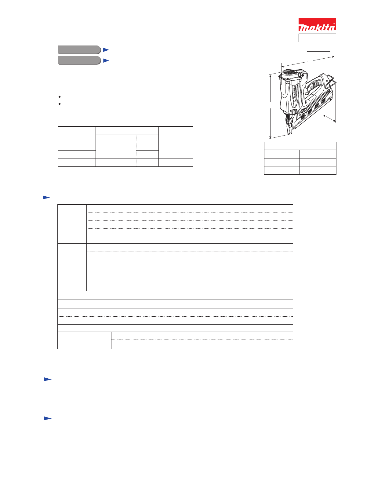
Dimensions: mm (")
Width*2 (W)
*2 with Hook
Height (H)
Length*2 (L)
108 (4-1/4)
321 (12-5/8)
368 (14-1/2)
Note: The standard equipment for the tool shown above may differ by country.
GN900
Cordless Clipped Head Framing Nailer
Model GN900 is a cordless clipped head nailer developed for a wide range of
framing applications. The main features are as follows:
Using fuel gas as the power source to provide freedom from hoses and compressors
Equipped with LED indication lamp with battery power warning and trouble detection
functions for convenience of operation and repair
Safety goggles ............................ 1
Hex wrench 4 ............................. 1
Plastic carrying case ................... 1
Magazine capacity
Nail
44 nails (1 strip)
50 - 90
(2 - 3-1/2)
2.9 - 3.3
(0.113 - 0.131)
Clipped-head
Length: mm (")
Gauge (Shank diameter): mm (")
Head type
34 degreeNail collation angle
Optional accessories
Nail fuel pack
Fuel cell
Cleaner kit (contains the following accessories in a special Tool bag: Cleaner/ 1, Lubricating oil/ 1,
Hex wrench 4/ 1, Brush/ 1, Cotton waste/ 1)
Charger DC07SA
Charger DC10WA
Battery BL7010
7.2
1.0
30
with DC07SA/DC10WA
Li-ion
Charging time (approx.): min.
Battery
YesAnti-dry-fire mechanism
Cell
Voltage: V
Capacity: Ah
Battery life*4
Fuel cell life*5
4,000 nails (approx.)
Motor*3 Coreless DC motor
1,200 nails (approx.)
3.2 (7.0)
3.4 (7.5)
without Battery and Fuel cell
with Battery and Fuel cell
Net weight: kg (lbs)
W
H
L
This product is available in the following variations.
The model also includes the accessories listed below in "Standard equipment".
GN900SE
GN900S
DC07SA
Model No.
type
No
Charger
No
quantity
No
1
2
BL7010
(Li-ion 1.0Ah)
Battery*1
GN900ZK
*3 The motor is used for gas mixing, air intake/exhaust, supply of cooling air.
*4 Battery life: the number of nails on a single full battery charge
*5 Fuel cell life: the number of nails per Fuel cell
*1 Battery is used as the power source for ignition spark,
gas mixing, air intake/exhaust and supply of cooling air.
P 2/ 16
R
epair
CAUTION: 1) Remove Battery, Fuel cell, Nail from the machine for safety before repair/ maintenance
in accordance with the instruction manual!
2) Loosen Hex socket head bolts with L-shape wrench in advance before removing them
using cordless impact driver with 1R228/ 1R229, or the top of 1R228/ 229 will damage.
[1] NECESSARY REPAIRING TOOLS
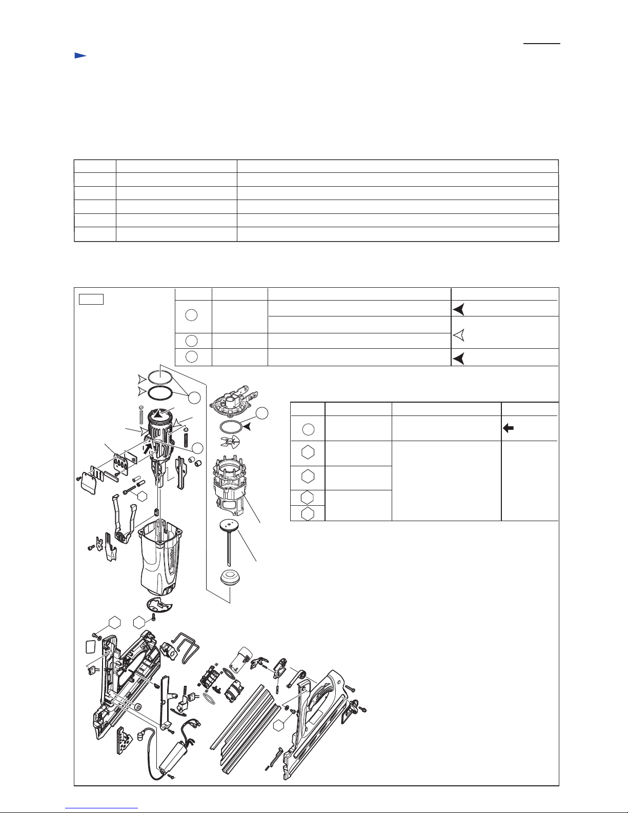
[2] LUBRICATIONS AND ADHESIVES
Fig. 1
Code No. Description Use for
1R005 Retaining ring pliers RT-2N Disassembling / Assembling Retaining ring R-58
1R228 1/4” Hex shank bit for M4 Disassembling / Assembling M4 Hex socket head bolt
1R229 1/4” Hex shank bit for M5 Disassembling / Assembling M5 Hex socket head bolt
1R268 Spring pin extractor 3 Disassembling / Assembling Spring pin 3-32
1R291 Retaining ring S and R pliers Disassembling / Assembling Retaining ring R-24
Item No.
Apply a little amount of Lubricant and Adhesives illustrated in Fig. 1.
Description Portion to lubricate Lubrication
Lubrication oil VG100
Lubrication oil VG100
Molybdenum
disulfide
a: Inside with which Driver complete contacts
b: Outside with which Chamber contacts
24
42
23
Cylinder ring Whole portion
O ring 60 Whole portion
Cylinder
24
b
b
42
23
17
9
c
67
97
a
ThreeBond1342
or
Loctite272
c: Rib portion on which
Exhaust plate is attached
23 Cylinder
Item No. Description Adhesive
ThreeBond
1215
Portion to glue
Thread
Driver complete
Exhaust plate
Chamber
M5x10 Hex
socket head bolt
M5x16 Hex
socket head bolt
M5x35 Hex
socket head bolt
9
97
17
67
P 3/ 16
R
epair
[3] DISASSEMBLY/ASSEMBLY
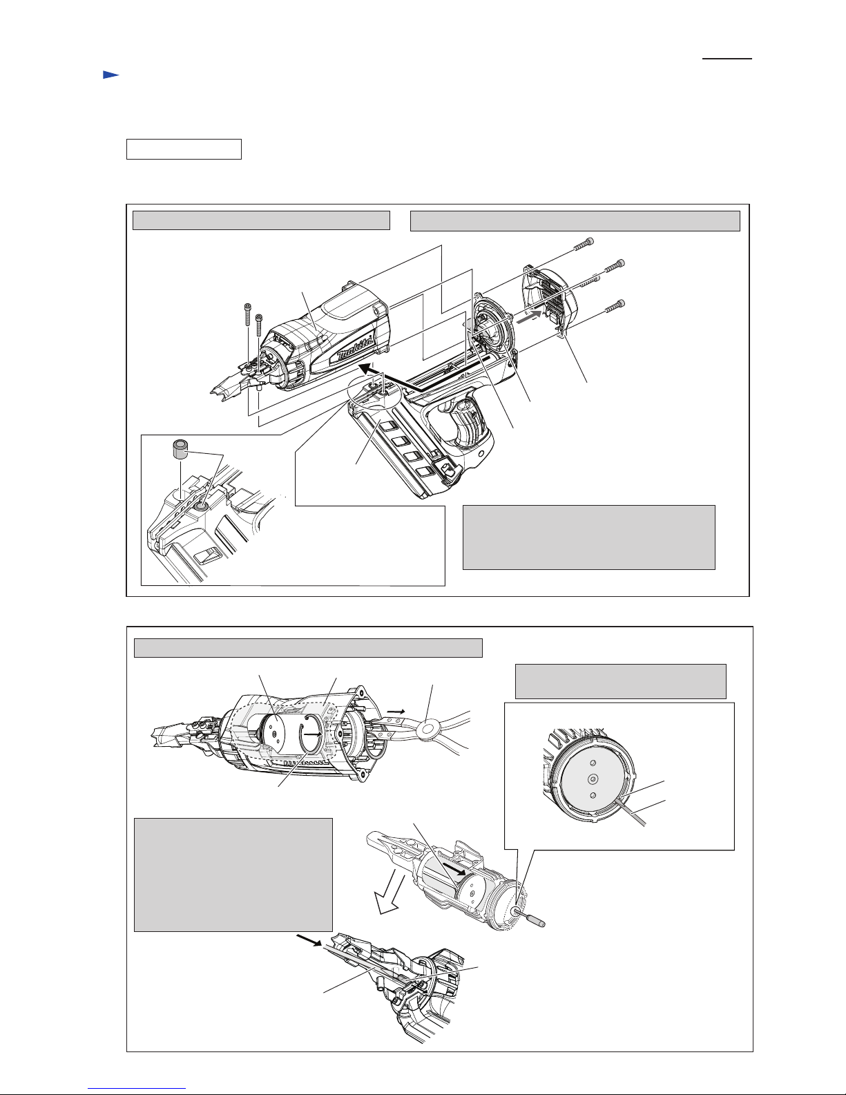
[3]-1. Driver, Front cushion
DISASSEMBLING
1) Remove M5x35 Hex socket head bolt (2pcs.)
Note: Sleeve 8 (2pcs.) may be
fallen from Handle set
in the disassembling step.
Therefore, pay attention
not to lose Sleeve 8.
1) Remove Retaining ring (INT) R-58 from Cylinder with 1R005.
2) Remove M5x25 Hex socket head bolt (4pcs.) and Top cap.
3) Hold Housing by hand and slide it straightly
and gently in order not to hook with Fan 60,
then lift Housing obliquely as designated in
black arrow.
Note: Do not deform Fan 60.
Handle set
Top cap
Cylinder head
Fan 60
M5x35 Hex socket
head bolt (2pcs.)
M5x25 Hex socket
head bolt (4pcs.)
Housing
(1) Disassemble Driver complete as illustrated in Figs. 2 and 3.
Fig. 2
Fig. 3
Sleeve 8
cylinder
1R005
Driver complete
Retaining ring (INT) R-58 on Cylinder
3) While holding Piston ring (2pcs.)
with the slotted screwdriver to
prevent them from being caught
in the groove for Retaining ring
(INT) R-58, push Driver complete
with another slotted screwdriver
toward Top cap side.
2) Insert slotted screwdriver along with
an vertical groove of Cylinder.
slotted
screwdriver
vertical groove
of Cylinder
Cylinder viewed from top cap side
Inside view
slotted screwdriver
end of Driver complete
Piston ring (2pcs.)
on Driver complete
P 4/ 16
R
epair
[3] DISASSEMBLY/ASSEMBLY
[3]-1. Driver, Front cushion (cont.)
DISASSEMBLING
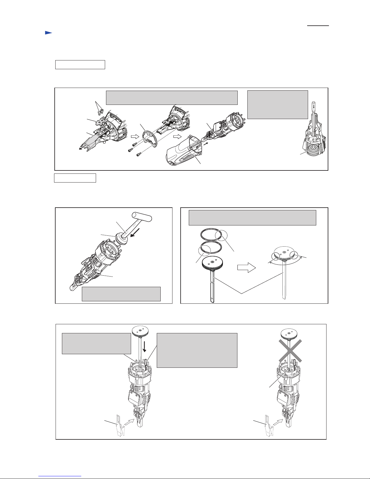
ASSEMBLING
M5x10 Hex socket
head bolt (2pcs.)
Separate Cylinder section from Housing after removing
Arm plate, Contact top and Front plate.
(2) Separate Cylinder section from Housing. And then disassemble Front cushion. (Fig. 4)
(1) Assemble Front cushion to Cylinder as illustrated in Fig. 5.
(2) Mount two Piston rings to Driver complete. (Fig. 6)
M5x16 Hex socket
head bolt (3pcs.)
Arm plate
Contact top
Front plate
Housing
Front cushion
Push Front cushion into Cylinder
with hammer until it stops.
Insert slotted screwdriver
from the nail exit side,
and push Front cushion
out of Cylinder section.
Fig. 4
Cylinder
section
Front cushion
hammer
more than
90 degrees
Assemble Piston ring (2pcs.) to Driver complete
so that the angle of their slits is more than 90 degrees.
slit
slit
slit
slit
Cylinder
Driver complete
Fig. 5 Fig. 6
Contact top Contact top
Use slotted screwdriver to prevent
Piston rings from being caught in
the groove of Cylinder for
Retaining ring (INT) R-58.
(Refer to Fig. 3.)
Set Driver complete in place
so that the flat tip faces
Contact top installation side.
Note: Do not face the chamfered tip
of Driver complete to Contact top
installation side
(3) Insert Driver complete into Cylinder as illustrated in Fig. 7.
(4) Inserting Cylinder section into Housing, tighten Front plate with M5x16 Hex socket head bolt (3pcs.).
Assemble Contact top and Arm plate. (Fig. 4)
(5) Assemble Retaining ring (INT) R-58 to the groove in Cylinder. (Fig. 3)
(6) Assemble Handle set to Housing. (Fig. 2)
Fig. 7
P 5/ 16
R
epair
[3] DISASSEMBLY/ASSEMBLY
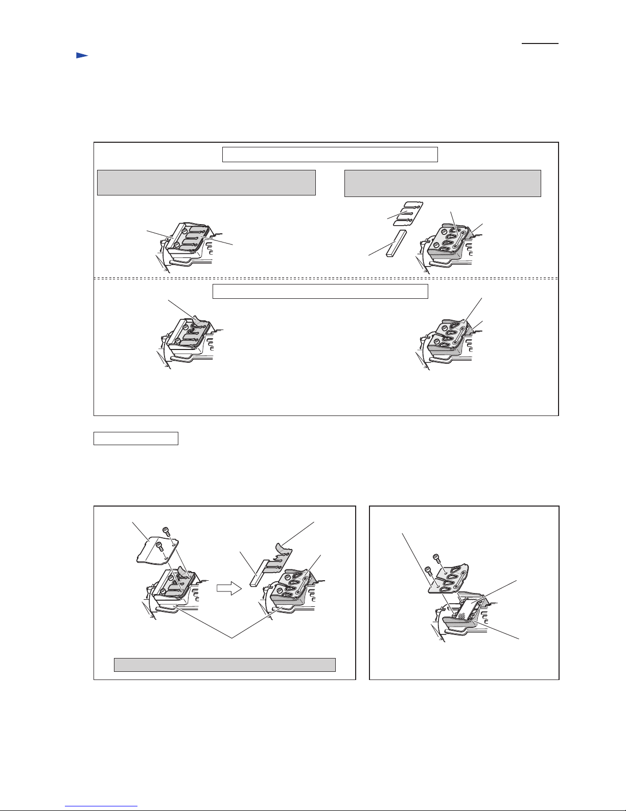
[3]-2. Exhaust valve section
DISASSEMBLING
When the tip of Driver complete does not hit the nail head in use, disassemble exhaust valve section to check malfunctions
as illustrated in Fig. 8.
Fig. 8
Exhaust valve is attached to four holes on Exhaust plate
when Driver complete moves to the lowest position.
Exhaust plate under Exhaust valve seals Cylinder
at the frame on Cylinder.
Exhaust plate
Exhaust valve
Exhaust valve
Punching metal
Exhaust plate
Exhaust plate
Exhaust cover
M4x10 Hex socket
head bolt (2pcs.)
M4x10 Hex socket
head bolt (2pcs.)
Exhaust valve
Silencer
Silencer
Cylinder
Disassemble Exhaust cover, Silencer and Exhaust valve.
Silencer
frame on Cylinder
frame on Cylinder
frame on Cylinder
Exhaust plate
It causes the wrong driving like dry fire and the leakage of gas.
Note: It is possible that the tip of Driver complete does not hit the nail head in use because of the corrosion of adhesive
even if Exhaust valve and Exhaust plate do not look deformed/ damaged.
Scrape away the adhesive and apply fresh ThreeBond to treat such a case. (Refer to next page.)
Exhaust valve
Deformed and damaged Exhaust valve / Exhaust plate
Normal condition of Exhaust valve and Exhaust plate
(1) Disassemble Handle set from Housing. (Fig. 2.)
(2) Remove Contact top, Arm plate and Front plate from Cylinder. And separate Cylinder section from Housing. (Fig.4)
(3) Disassemble Exhaust mechanism as illustrated in Figs. 9 and 10.
Fig. 9 Fig. 10
 Loading...