

Page 1
INSTRUCTION MANUAL
MANUEL D'INSTRUCTION
MANUAL DE INSTRUCCIONES
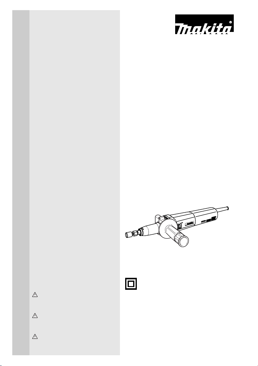
Die Grinder
Meuleuse droite
Rectificador
GD0800C
GD0810C
003486
DOUBLE INSULATION
DOUBLE ISOLATION
DOBLE AISLAMIENTO
WARNING:
For your personal safety, READ and UNDERSTAND before using.
SAVE THESE INSTRUCTIONS FOR FUTURE REFERENCE.
AVERTISSEMENT:
Pour votre propre sécurité, prière de lire attentivement avant l’utilisation.
GARDER CES INSTRUCTIONS POUR RÉFÉRENCE ULTÉRIEURE.
ADVERTENCIA:
Para su seguridad personal, LEA DETENIDAMENTE este manual antes de usar la herramienta.
GUARDE ESTAS INSTRUCCIONES PARA FUTURA REFERENCIA.
Page 2

ENGLISH
SPECIFICATIONS
Model GD0800C GD0810C
Collet size 1/4” 1/4”
Max. wheel point diameter 25 mm (1”) 50 mm (2”)
No load speed (RPM) 7,000 - 28,000/min. 1,800 - 7,000/min.
Overall length 371 mm (14 - 5/8”) 371 mm (14 - 5/8”)
Net weight 1.6 kg (3.5 lbs) 1.7 kg (3.7 lbs)
• Due to our continuing programme of research and development, the specifications herein are subject to change
without notice.
• Note: Specifications may differ from country to country.
GENERAL SAFETY RULES
USA002-2
(For All Tools)
WARNING:
Read and understand all instructions.
Failure to follow all instructions listed below,
may result in electric shock, fire and/or serious personal injury.
SAVE THESE INSTRUCTIONS
Work Area
1. Keep your work area clean and well lit. Cluttered
benches and dark areas invite accidents.
2. Do not operate power tools in explosive atmo-
spheres, such as in the presence of flammable
liquids, gases, or dust. Power tools create sparks
which may ignite the dust or fumes.
3. Keep bystanders, children, and visitors away
while operating a power tool. Distractions can
cause you to lose control.
Electrical Safety
4. Double insulated tools are equipped with a
polarized plug (one blade is wider than the
other.) This plug will fit in a polarized outlet only
one way. If the plug does not fit fully in the outlet,
reverse the plug. If it still does not fit, contact a
qualified electrician to install a polarized outlet.
Do not change the plug in any way. Double insula-
tion eliminates the need for the three wire
grounded power cord and grounded power supply
system.
5. Avoid body contact with grounded surfaces
such as pipes, radiators, ranges and refrigerators. There is an increased risk of electric shock if
your body is grounded.
6. Do not expose power tools to rain or wet conditions. Water entering a power tool will increase the
risk of electric shock.
7. Do not abuse the cord. Never use the cord to
carry the tools or pull the plug from an outlet.
Keep cord away from heat, oil, sharp edges or
moving parts. Replace damaged cords immediately. Damaged cords increase the risk of electric
shock.
8. When operating a power tool outside, use an
outdoor extension cord marked “W-A” or “W”.
These cords are rated for outdoor use and reduce
the risk of electric shock.
Personal Safety
9. Stay alert, watch what you are doing and use
common sense when operating a power tool. Do
not use tool while tired or under the influence of
drugs, alcohol, or medication. A moment of inat-
tention while operating power tools may result in
serious personal injury.
10. Dress properly. Do not wear loose clothing or
jewelry. Contain long hair. Keep your hair, clothing, and gloves away from moving parts. Loose
clothes, jewelry, or long hair can be caught in moving parts.
11. Avoid accidental starting. Be sure switch is off
before plugging in. Carrying tools with your finger
on the switch or plugging in tools that have the
switch on invites accidents.
12. Remove adjusting keys or wrenches before turning the tool on. A wrench or a key that is left
attached to a rotating part of the tool may result in
personal injury.
13. Do not overreach. Keep proper footing and balance at all times. Proper footing and balance
enables better control of the tool in unexpected situations.
14. Use safety equipment. Always wear eye protection. Dust mask, non-skid safety shoes, hard hat, or
2
Page 3

hearing protection must be used for appropriate conditions. Ordinary eye or sun glasses are NOT eye
protection.
Tool Use and Care
15. Use clamps or other practical way to secure and
support the workpiece to a stable platform. Hold-
ing the work by hand or against your body is unstable and may lead to loss of control.
16. Do not force tool. Use the correct tool for your
application. The correct tool will do the job better
and safer at the rate for which it is designed.
17. Do not use tool if switch does not turn it on or
off. Any tool that cannot be controlled with the
switch is dangerous and must be repaired.
18. Disconnect the plug from the power source
before making any adjustments, changing
accessories, or storing the tool. Such preventive
safety measures reduce the risk of starting the tool
accidentally.
19. Store idle tools out of reach of children and
other untrained persons. Tools are dangerous in
the hands of untrained users.
20. Maintain tools with care. Keep cutting tools
sharp and clean. Properly maintained tools with
sharp cutting edges are less likely to bind and are
easier to control.
21. Check for misalignment or binding of moving
parts, breakage of parts, and any other condition
that may affect the tools operation. If damaged,
have the tool serviced before using. Many acci-
dents are caused by poorly maintained tools.
22. Use only accessories that are recommended by
the manufacturer for your model. Accessories
that may be suitable for one tool, may become hazardous when used on another tool.
SERVICE
23. Tool service must be performed only by qualified
repair personnel. Service or maintenance per-
formed by unqualified personnel could result in a risk
of injury.
24. When servicing a tool, use only identical
replacement parts. Follow instructions in the
Maintenance section of this manual. Use of unau-
thorized parts or failure to follow Maintenance
instructions may create a risk of electric shock or
injury.
USE PROPER EXTENSION CORD: Make sure your
extension cord is in good condition. When using an
extension cord, be sure to use one heavy enough to
carry the current your product will draw. An undersized
cord will cause a drop in line voltage resulting in loss of
power and overheating. Table 1 shows the correct size to
use depending on cord length and nameplate ampere
rating. If in doubt, use the next heavier gage. The smaller
the gage number, the heavier the cord.
Table 1: Minimum gage for cord
Ampere Rating
Volts Total length of cord in feet
120 V 25 ft. 50 ft. 100 ft. 150 ft.
More Than Not More Than AWG
0 6 18 16 16 14
18 16 14 12610
10 12 16 16 14 12
12 16 14 12
Not Recommended
SPECIFIC SAFETY RULES
USB006-2
DO NOT let comfort or familiarity with
product (gained from repeated use)
replace strict adherence to grinder safety
rules. If you use this tool unsafely or
incorrectly, you can suffer serious personal injury.
1. Accessories must be rated for at least the speed
recommended on the tool warning label. Wheels
and other accessories running over rated speed can
fly apart and cause injury.
2. Hold tool by insulated gripping surfaces when
performing an operation where the cutting tool
may contact hidden wiring or its own cord. Con-
tact with a “live” wire will make exposed metal parts
of the tool “live” and shock the operator.
3. Always use safety glasses or goggles. Ordinary
eye or sun glasses are NOT safety glasses.
4. Check the wheel carefully for cracks or damage
before operation. Replace cracked or damaged
wheel immediately. Run the tool at no load for
about a minute, holding tool away from others. If
wheel is flawed, it will likely separate during this
test.
5. Hold the tool firmly.
6. Keep hands away from rotating parts.
3
Page 4
7. Make sure the wheel is not contacting the workpiece before the switch is turned on.
8. Before using the tool on an actual workpiece, let
it run for a while. Watch for vibration or wobbling
that could indicate poor installation or a poorly
balanced wheel.
9. Watch out for flying sparks. Hold the tool so that
sparks fly away from you and other persons or
flammable materials.
10. Do not leave the tool running. Operate the tool
only when hand-held.
11. Do not touch the workpiece immediately after
operation; it may be extremely hot and could
burn your skin.
12. Always be sure you have a firm footing. Be sure
no one is below when using the tool in high locations.
13. Do not use water or grinding lubricant.
14. Do not use this tool as cutter.
15. ALWAYS wear proper apparel including long
sleeve shirts, leather gloves and shop aprons to
protect skin from contact with hot grindings.
16. Use of this tool to grind or sand some products,
paints and wood could expose user to dust containing hazardous substances. Use appropriate
respiratory protection.
SAVE THESE INSTRUCTIONS
WARNING:
MISUSE or failure to follow the safety
rules stated in this instruction manual
may cause serious personal injury.
SYMBOLS
The followings show the symbols used for tool.
V............................volts
A ...........................amperes
Hz..........................hertz
....................alternating current
.......................no load speed
.......................Class II Construction
.../min....................revolutions or reciprocation per
minute
USD201-2
FUNCTIONAL DESCRIPTION
CAUTION:
• Always be sure that the tool is switched off and
unplugged before adjusting or checking function on
the tool.
Switch action
CAUTION:
• Before plugging in the tool, always check to see
that the slide switch actuates properly and returns
to the “OFF” position when the rear of the slide
switch is depressed.
• Switch can be locked in “ON” position for ease of
operator comfort during extended use. Apply caution when locking tool in “ON” position and maintain
firm grasp on tool.
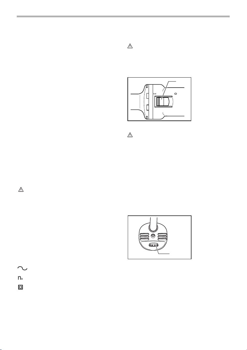
To start the tool, slide the slide switch toward the “I (ON)”
position. For continuous operation, press the front of the
slide switch to lock it.
To stop the tool, press the rear of the slide switch, then
slide it toward the “O (OFF)” position.
Speed adjusting dial
2
The tool speed can be changed by turning the speed
adjusting dial to a given number setting from 1 to 5.
Higher speed is obtained when the dial is turned in the
direction of number 5. And lower speed is obtained when
it is turned in the direction of number 1.
Refer to the table for the relationship between the number settings on the dial and the approximate tool speed.
003488
1. Slide switch
1
001046
1. Speed adjusting dial
1
4
Page 5
Number
1 - 2
2 - 3
3 - 4
4 - 5
GD0800C
RPM
7,000 - 10,000
10,000 - 17,000
17,000 - 24,000
24,000 - 28,000
GD0810C
RPM
1,800 - 2,400
2,400 - 4,100
4,100 - 5,800
5,800 - 7,000
003490
To remove the wheel point, follow the installation procedure in reverse.
003495
CAUTION:
• If the tool is operated continuously at low speeds for
a long time, the motor will get overloaded, resulting
in tool malfunction.
• The speed adjusting dial can be turned only as far
as 5 and back to 1. Do not force it past 5 or 1, or the
speed adjusting function may no longer work.
ASSEMBLY
CAUTION:
• Always be sure that the tool is switched off and
unplugged before carrying out any work on the tool.
Installing the side handle
1
Always use the side handle to ensure operating safety.
Install the side handle on the tool barrel, then tighten the
handle by turning clockwise at the desired position.
Installing or removing wheel point
1
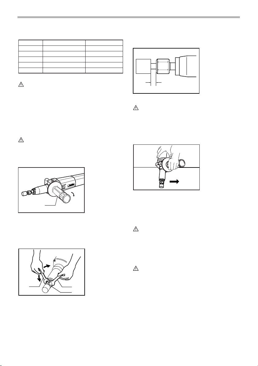
Loosen the collet nut and insert the wheel point into the
collet nut. Use the smaller wrench to hold the spindle and
the larger one to tighten the collet nut securely.
The wheel point should not be mounted more than 8 mm
(5/16”) from the collet nut. Exceeding this distance could
cause vibration or a broken shaft.
003491
1. Side handle
003493
1. Wrench 19
2. Wrench 13
3. Collet nut
2
3
8mm(5/16”)Max.
CAUTION:
• A 1/4” collet cone is provided as standard equip-
ment. Use an optional collet cone 1/8” to install a 1/
8” shank wheel point.
OPERATION
003497
Turn the tool on without the wheel point making any contact with the workpiece and wait until the wheel point
attains full speed. Then apply the wheel point to the
workpiece gently. To obtain a good finish, move the tool
in the leftward direction slowly.
CAUTION:
• Apply light pressure on the tool. Excessive pres-
sure on the tool will only cause a poor finish and
overloading of the motor.
MAINTENANCE
CAUTION:
• Always be sure that the tool is switched off and
unplugged before attempting to perform inspection
or maintenance.
To maintain product SAFETY and RELIABILITY, repairs,
carbon brush inspection and replacement, any other
maintenance or adjustment should be performed by Makita Authorized or Factory Service Centers, always using
Makita replacement parts.
5
Page 6

ACCESSORIES
CAUTION:
• These accessories or attachments are recom-
mended for use with your Makita tool specified in
this manual. The use of any other accessories or
attachments might present a risk of injury to persons. Only use accessory or attachment for its
stated purpose.
If you need any assistance for more details regarding
these accessories, ask your local Makita Service Center.
• Wheel points
• Collet cone set (1/4”, 1/8”)
• Wrench 13
• Wrench 19
• Side handle set
MAKITA LIMITED ONE YEAR WARRANTY
Warranty Policy
Every Makita tool is thoroughly inspected and tested
before leaving the factory. It is warranted to be free of
defects from workmanship and materials for the period of
ONE YEAR from the date of original purchase. Should
any trouble develop during this one year period, return
the COMPLETE tool, freight prepaid, to one of Makita’s
Factory or Authorized Service Centers. If inspection
shows the trouble is caused by defective workmanship or
material, Makita will repair (or at our option, replace)
without charge.
This Warranty does not apply where:
• repairs have been made or attempted by others:
• repairs are required because of normal wear and
tear:
• the tool has been abused, misused or improperly
maintained:
• alterations have been made to the tool.
IN NO EVENT SHALL MAKITA BE LIABLE FOR ANY
INDIRECT, INCIDENTAL OR CONSEQUENTIAL DAMAGES FROM THE SALE OR USE OF THE PRODUCT.
THIS DISCLAIMER APPLIES BOTH DURING AND
AFTER THE TERM OF THIS WARRANTY.
MAKITA DISCLAIMS LIABILITY FOR ANY IMPLIED
WARRANTIES, INCLUDING IMPLIED WARRANTIES
OF “MERCHANTABILITY” AND “FITNESS FOR A SPECIFIC PURPOSE,” AFTER THE ONE YEAR TERM OF
THIS WARRANTY.
This Warranty gives you specific legal rights, and you
may also have other rights which vary from state to state.
Some states do not allow the exclusion or limitation of
incidental or consequential damages, so the above limitation or exclusion may not apply to you. Some states do
not allow limitation on how long an implied warranty lasts,
so the above limitation may not apply to you.
EN0006-1
6
Page 7

FRANÇAIS
SPÉCIFICATIONS
Modèle GD0800C GD0810C
Dimension de la bague de mandrin 1/4” 1/4”
Diamètre max. de meule sur tige 25 mm (1”) 50 mm (2”)
Vitesse à vide (T/MIN) 7,000 - 28,000/min. 1,800 - 7,000/min.
Longueur totale 371 mm (14 - 5/8”) 371 mm (14 - 5/8”)
Poids net 1.6 kg (3.5 lbs) 1.7 kg (3.7 lbs)
• Le fabricant se réserve le droit de modifier sans avertissement les spécifications.
• Note: Les spécifications peuvent varier selon les pays.
RÈGLES DE SÉCURITÉ
GÉNÉRALES
USA002-2
(Pour tous les outils)
AVERTISSEMENT:
Vous devez lire et comprendre toutes les
instructions. Le non-respect, même partiel,
des instructions ci-après entraîne un risque
de choc électrique, d’incendie et/ou de
blessures graves.
CONSERVEZ CES
INSTRUCTIONS
Aire de travail
1. Veillez à ce que l’aire de travail soit propre et
bien éclairée. Le désordre et le manque de lumière
favorisent les accidents.
2. N’utilisez pas d’outils électriques dans une
atmosphère explosive, par exemple en présence
de liquides, de gaz ou de poussières
inflammables. Les outils électriques créent des
étincelles qui pourraient enflammer les poussières
ou les vapeurs.
3. Tenez à distance les curieux, les enfants et les
visiteurs pendant que vous travaillez avec un
outil électrique. lls pourraient vous distraire et vous
faire une fausse manoeuvre.
Sécurité électrique
4. Les outils à double isolation sont équipés d’une
fiche polarisée (une des lames est plus large que
l’autre), qui ne peut se brancher que d'une seule
façon dans une prise polarisée. Si la fiche
n’entre pas parfaitement dans la prise, inversez
sa position ; si elle n’entre toujours pas bien,
demandez à un électricien qualifié d’installer une
prise de courant polarisée. Ne modifiez pas la
fiche de l’outil. La double isolation élimine le
besoin d’un cordon d’alimentation à trois fils avec
mise à la terre ainsi que d’une prise de courant mise
à la terre.
5. Évitez tout contact corporel avec des surfaces
mises à la terre (tuyauterie, radiateurs,
cuisinières, réfrigérateurs, etc.). Le risque de
choc électrique est plus grand si votre corps est en
contact avec la terre.
6. N’exposez pas les outils électriques à la pluie ou
à l’eau. La présence d’eau dans un outil électrique
augmente le risque de choc électrique.
7. Ne maltraitez pas le cordon. Ne transportez pas
l’outil par son cordon et ne débranchez pas la
fiche en tirant sur le cordon. N’exposez pas le
cordon à la chaleur, à des huiles, à des arêtes
vives ou à des pièces en mouvement.
Remplacez immédiatement un cordon
endommagé. Un cordon endommagé augmente le
risque de choc électrique.
8. Lorsque vous utilisez un outil électrique à
l’extérieur, employez un prolongateur pour
l’extérieur marqué “W-A” ou “W”. Ces cordons
sont faits pour être utilisés à l’extérieur et réduisent
le risque de choc électrique.
Sécurité des personnes
9. Restez alerte, concentrez-vous sur votre travail
et faites preuve de jugement. N’utilisez pas un
outil électrique si vous êtes fatigué ou sous
l'influence de drogues, d’alcool ou de
médicaments. Un instant d’inattention suffit pour
entraîner des blessures graves.
10. Habillez-vous convenablement. Ne portez ni
vêtements flottants ni bijoux. Confinez les
cheveux longs. N’approchez jamais les
cheveux, les vêtements ou les gants des pièces
en mouvement. Des vêtements flottants, des bijoux
ou des cheveux longs risquent d’être happés par
des pièces en mouvement.
7
Page 8

11. Méfiez-vous d’un démarrage accidentel. Avant
de brancher l’outil, assurez-vous que son
interrupteur est sur ARRÊT. Le fait de transporter
un outil avec le doigt sur la détente ou de brancher
un outil dont l’interrupteur est en position MARCHE
peut mener tout droit à un accident.
12. Enlevez les clés de réglage ou de serrage avant
de démarrer l’outil. Une clé laissée dans une pièce
tournante de l’outil peut provoquer des blessures.
13. Ne vous penchez pas trop en avant. Maintenez
un bon appui et restez en équilibre en tout
temps. Un bonne stabilité vous permet de mieux
réagir à une situation inattendue.
14. Utilisez des accessoires de sécurité. Portez
toujours des lunettes ou une visière. Selon les
conditions, portez aussi un masque antipoussière,
des bottes de sécurité antidérapantes, un casque
protecteur et/ou un appareil antibruit. Les lunettes
ordinaires et les lunettes de soleil NE constituent
PAS des lunettes de protection.
Utilisation et entretien des outils
15. Immobilisez le matériau sur une surface stable
au moyen de brides ou de toute autre façon
adéquate. Le fait de tenir la pièce avec la main ou
contre votre corps offre une stabilité insuffisante et
peut amener un dérapage de l’outil.
16. Ne forcez pas l’outil. Utilisez l’outil approprié à
la tâche. L’outil correct fonctionne mieux et de façon
plus sécuritaire. Respectez aussi la vitesse de
travail qui lui est propre.
17. N’utilisez pas un outil si son interrupteur est
bloqué. Un outil que vous ne pouvez pas
commander par son interrupteur est dangereux et
doit être réparé.
18. Débranchez la fiche de l’outil avant d’effectuer
un réglage, de changer d’accessoire ou de
ranger l’outil. De telles mesures préventives de
sécurité réduisent le risque de démarrage accidentel
de l’outil.
19. Rangez les outils hors de la portée des enfants
et d’autres personnes inexpérimentées. Les
20. Prenez soin de bien entretenir les outils. Les
21. Soyez attentif à tout désalignement ou
22. N’utilisez que des accessoires que le fabricant
RÉPARATI ON
23. La réparation des outils électriques doit être
24. Pour la réparation d’un outil, n’employez que
UTLISEZ UN CORDON PROLONGATEUR ADÉQUAT:
Assurez-vous que le cordon prolongateur est en bon
état. Lors de l’utilisation d’un cordon prolongateur,
utilisez sans faute un cordon assez gros pour conduire le
courant que le produit nécessite. Un cordon trop petit
provoquera une baisse de tension de secteur, résultant
en une perte de puissance et une surchauffe. Le Tableau
1 indique la dimension appropriée de cordon selon sa
longueur et selon l’intensité nominale indiquée sur la
plaque signalétique. En cas de doute sur un cordon
donné, utilisez le cordon suivant (plus gros). Plus le
numéro de gabarit indiqué est petit, plus le cordon est
gros.
Tableau 1. Gabarit minimum du cordon
Intensit
é nominale
Volts Longueur totale du cordon en pieds
120 V 25 pi 50 pi 100 pi 150 pi
Plus de Pas plus de Calibre am
0 6 18 16 16 14
10 12 16 16 14 12
12 16 14 12
outils sont dangereux dans les mains d’utilisateurs
novices.
outils de coupe doivent être toujours bien
affûtés et propres. Des outils bien entretenus, dont
les arêtes sont bien tranchantes, sont moins
susceptibles de coincer et plus faciles à diriger.
coincement des pièces en mouvement, à tout
bris ou à toute autre condition préjudiciable au
bon fonctionnement de l’outil. Si vous constatez
qu’un outil est endommagé, faites-le réparer
avant de vous en servir. De nombreux accidents
sont causés par des outils en mauvais état.
recommande pour votre modèle d’outil. Certains
accessoires peuvent convenir à un outil, mais être
dangereux avec un autre.
confiée à un réparateur qualifié. L’entretien ou la
réparation d’un outil électrique par un amateur peut
avoir des conséquences graves.
des pièces de rechange d’origine. Suivez les
directives données à la section «ENTRETIEN» de
ce manuel. L’emploi de pièces non autorisées ou le
non-respect des instructions d’entretien peut créer
un risque de choc électrique ou de blessures.
éricain des fils
18 16 14 12610
Non recommand
é
8
Page 9

RÈGLES DE SÉCURITÉ
PARTICULI ÈRES
USB006-2
NE vous laissez PAS tromper (au fil d’une
utilisation répétée) par un sentiment
d’aisance et de familiarité avec le
produit, en négligeant le respect
rigoureux des consignes de sécurité qui
accompagnent la meuleuse. L’utilisation
non sécuritaire ou incorrecte de cet outil
comporte un risque de blessure grave.
1. Les accessoires utilisés doivent être conçus
pour être utilisés au moins à la vitesse
recommandée sur l’étiquette d’avertissement de
l’outil. Toute meule ou tout accessoire utilisé à une
vitesse supérieure à sa capacité risque de voler en
éclats et de causer des blessures.
2. Tenez l’outil par ses surfaces de prise isolées
pendant toute opération où l’outil de coupe
pourrait venir en contact avec un câblage
dissimulé ou avec son propre cordon. En cas de
contact avec un conducteur sous tension, les pièces
métalliques à découvert de l’outil transmettraient un
choc électrique à l’utilisateur.
3. Portez toujours des lunettes de sécurité ou des
lunettes à coques. Les lunettes ordinaires et les
lunettes de soleil ne sont PAS des lunettes de
sécurité.
4. Avant l’utilisation, vérifiez toujours
soigneusement l’absence de fissures ou de
dommages sur la meule. Remplacez
immédiatement toute meule fissurée ou
endommagée. Faites tourner l’outil à vide
pendant environ une minute, en maintenant
l’outil éloigné de toute autre personne présente.
Si la meule comporte un défaut de fabrication,
elle se cassera probablement au cours de ce
test.
5. Tenez l’outil fermement.
6. Gardez les mains éloignées des pièces en
rotation.
7. Assurez-vous que la meule n’entre pas en
contact avec la pièce avant de mettre l’outil sous
tension.
8. Avant d’utiliser l’outil sur la pièce elle-même,
laissez-le tourner un instant. Soyez attentif à
toute vibration ou sautillement pouvant indiquer
que la meule n’est pas bien installée ou qu’elle
est mal équilibrée.
9. Prenez garde aux étincelles qui jaillissent. Tenez
l’outil de sorte que les étincelles ne jaillissent
pas vers vous, vers une personne présente ou
vers un matériau inflammable.
10. N’abandonnez pas l’outil alors qu’il tourne. Ne
faites fonctionner l’outil qu’une fois que vous
l’avez bien en main.
11. Ne touchez pas la pièce immédiatement après
l’utilisation ; elle peut être très chaude et brûler
votre peau.
12. Veillez à garder toujours une bonne assise.
Assurez-vous que personne ne se trouve audessous de vous quand vous utilisez l’outil en
situation élevée.
13. N’utilisez pas d’eau ou de lubrifiant à meulage.
14. N’utilisez pas cet outil comme couteau.
15. Portez TOUJOURS des vêtements adéquats pour
protéger la peau du contact avec des pièces
meulées encore chaudes, ces vêtements
incluant les chandails à manches longues, les
gants de cuir et les tabliers de travail.
16. L’utilisation de cet outil pour meuler ou poncer
certains produits, les surfaces peintes et le bois
peut exposer l’utilisateur à des poussières qui
contiennent des substances dangereuses.
Veuillez porter une protection des voies
respiratoires adéquate.
CONSERVEZ CE MODE
D’EMPLOI
AVERTISSEMENT:
Une MAUVAISE UTILISATION de l’outil ou
l’ignorance des consignes de sécurité du
présent manuel d’instructions peuvent
entraîner une grave blessure.
SYMBOLES
Les symboles utilisés pour l’outil sont présentés cidessous.
V ...........................volts
A...........................ampères
Hz .........................hertz
...................courant alternatif
.......................vitesse à vide
.......................construction, catégorie II
.../min ...................tours ou alternances par minute
USD201-2
9
Page 10

DESCRIPTION DU
FONCTIONNEMENT
ATTENTION:
• Assurez-vous toujours que l’outil est hors tension et
débranché avant de l’ajuster ou de vérifier son
fonctionnement.
Interrupteur
ATTENTION:
• Avant de brancher l’outil, assurez-vous toujours
que la gâchette fonctionne correctement et revient
en position d’“OFF” lorsque la partie arrière de
l’interrupteur à glissière est enfoncée.
• Pour rendre le travail de l’utilisateur plus confortable
lors d’une utilisation prolongée, l’interrupteur peut
être verrouillé en position de marche. Soyez
prudent lorsque vous verrouillez l’outil en position
de marche, et maintenez une poigne solide sur
l’outil.
Pour mettre l’outil en marche, faites glisser l’interrupteur
à glissière vers la positon d’“I (ON)". Pour une utilisation
continue, appuyez sur la partie avant de l’interrupteur à
glissière pour le verrouiller.
Pour arrêter l’outil, appuyez sur la partie arrière de
l’interrupteur à glissière, puis faites-le glisser vers la
position d’“O (OFF)".
Cadran de rélage de vitesse
2
La vitesse de l’outil peut-être modifiée en faisant tourner
le cadran de réglage de la vitesse sur un numéro de
réglage donné, de 1 à 5.
Une vitesse plus élevée est obtenue lorsque le cadran
est tourné vers le numéro 5. Et une vitesse plus basse
est obtenue lorsqu’il est tourné vers le numéro 1.
003488
1. Interrupteur à
1
1
glissière
001046
1. Cadran de
réglage de la
vitesse
Référez-vous au tableau, qui indique la relation entre le
numéro de réglage sur le cadran et la vitesse
approximative de l’outil.
Numéro
1 - 2
2 - 3
3 - 4
4 - 5
ATTENTION:
• Si l’outil est utilisé de manière continue à vitesse
réduite sur une période prolongée, le moteur sera
surchargé et cela entraînera un mauvais
fonctionnement de l’outil.
• Le cadran de réglage de la vitesse ne peut pas
dépasser le 5 et le 1. Ne le forcez pas à dépasser le
5 ou le 1, sinon la fonction de réglage de la vitesse
risque de ne plus fonctionner.
GD0800C
T/MIN
7.000 - 10.000
10.000 - 17.000
17.000 - 24.000
24.000 - 28.000
GD0810C
1.800 - 2.400
2.400 - 4.100
4.100 - 5.800
5.800 - 7.000
003490
T/MIN
ASSEMBLAGE
ATTENTION:
• Avant d’effectuer toute intervention sur l’outil,
assurez-vous toujours qu’il est hors tension et
débranché.
Installation de la poignée latérale
1
Utilisez toujours la poignée latérale pour assurer que le
travail s’effectuera en toute sécurité. Installez la poignée
latérale sur le baril de l’outil, puis serrez la poignée en la
tournant dans le sens des aiguilles d’une montre sur la
position désirée.
Installation ou retrait de la meule sur tige
1
003491
1. Poignée latérale
003493
1. Clé 19
2. Clé 13
3. Ecrou à collet
2
3
10
Page 11

Desserrez l’écrou de mandrin et insérez-y la meule sur
tige. Utilisez la plus petite clé pour immobiliser l’arbre, et
serrez fermement l’écrou de mandrin à l’aide de la plus
grande.
La meule sur tige ne doit pas être montée à plus de 8
mm (5/16”) de l’écrou de mandrin. Une trop grande
distance peut entraîner des vibrations ou la cassure de
l’arbre.
Pour retirer la meule sur tige, suivez la procédure
d’installation en sens inverse.
8mm(5/16”)Max.
ATTENTION:
• Un cône de mandrin 1/4” est fourni en équipement
standard. Utilisez un cône de mandrin 1/8” en
option pour installer une meule sur tige à arbre 1/8”.
003495
UTILISATION
003497
Mettez l’appareil en marche sans mettre la meule sur tige
en contact avec la pièce à travailler, et attendez que la
meule sur tige atteigne sa pleine vitesse. Puis appuyez
légèrement la meule sur tige sur la pièce à travailler. Pour
obtenir une bonne finition, déplacez lentement l’outil vers
la gauche.
ATTENTION:
• N’appliquez qu’une légère pression sur l’outil. Une
pression trop grande sur l’outil résulterait en une
piètre finition et entraînerait une surcharge du
moteur.
ENTRETIEN
ATTENTION:
• Assurez-vous toujours que l’outil est hors tension et
débranché avant d’y effectuer tout travail
d’inspection ou d’entretien.
Pour maintenir la SÉCURITÉ et la FIABILITÉ du produit,
les réparations, l’inspection et le remplacement des
charbons, et tout autre travail d’entretien ou de réglage
doivent être effectués dans une usine ou un centre de
service après-vente Makita agréé, exclusivement avec
des pièces de rechange Makita.
ACCESSOIRES
ATTENTION:
• Ces accessoires ou pièces complémentaires sont
recommandés pour l’utilisation avec l’outil Makita
spécifié dans ce mode d’emploi. L’utilisation de tout
autre accessoire ou pièce complémentaire peut
comporter un risque de blessure. N’utilisez les
accessoires ou pièces qu’aux fins auxquelles ils ont
été conçus.
Si vous désirez obtenir plus de détails concernant ces
accessoires, veuillez contacter le centre de service
après-vente Makita le plus près.
• Meules sur tige
• Ensemble de cône de mandrin (1/4”, 1/8”)
• Clé 13
• Clé 19
• Ensemble de poignée latérale
GARANTIE LIMITÉE D’UN AN MAKITA
Politique de garantie
Chaque outil Makita est inspecté rigoureusement et testé
avant sa sortie d’usine. Nous garantissons qu’il sera
exempt de défaut de fabrication et de vice de matériau
pour une période d’UN AN à partir de la date de son
achat initial. Si un problème quelconque devait survenir
au cours de cette période d’un an, veuillez retourner
l’outil COMPLET, port payé, à une usine ou à un centre
de service après-vente Makita. Makita réparera l’outil
gratuitement (ou le remplacera, à sa discrétion) si un
défaut de fabrication ou un vice de matériau est
découvert lors de l’inspection.
Cette garantie ne s’applique pas dans les cas où:
• des réparations ont été effectuées ou tentées par
un tiers:
• des réparations s’imposent suite à une usure
normale:
• l’outil a été malmené, mal utilisé ou mal entretenu:
• l’outil a subi des modifications.
MAKITA DÉCLINE TOUTE RESPONSABILITÉ POUR
TOUT DOMMAGE ACCESSOIRE OU INDIRECT LIÉ À
LA VENTE OU À L’UTILISATION DU PRODUIT. CET
AVIS DE NON-RESPONSABILITÉ S’APPLIQUE À LA
FOIS PENDANT ET APRÈS LA PÉRIODE COUVERTE
PAR CETTE GARANTIE.
MAKITA DÉCLINE TOUTE RESPONSABILITÉ QUANT
À TOUTE GARANTIE TACITE, INCLUANT LES
GARANTIES TACITES DE “QUALITÉ MARCHANDE” ET
“ADÉQUATION À UN USAGE PARTICULIER” APRÈS
11
EN0006-1
Page 12

LA PÉRIODE D’UN AN COUVERTE PAR CETTE
GARANTIE.
Cette garantie vous donne des droits spécifiques
reconnus par la loi, et possiblement d’autres droits, qui
varient d’un État à l’autre. Certains États ne permettant
pas l’exclusion ou la limitation des dommages
accessoires ou indirects, il se peut que la limitation ou
exclusion ci-dessus ne s’applique pas à vous. Certains
États ne permettant pas la limitation de la durée
d’application d’une garantie tacite, il se peut que la
limitation ci-dessus ne s’applique pas à vous.
12
Page 13

ESPAÑOL
ESPECIFICACIONES
Modelo GD0800C GD0810C
Especificaciones eléctricas en México
Ta ma ño del porta piezas 1/4” 1/4”
Diámetro máx. de la punta de la rueda 25 mm (1”) 50 mm (2”)
Revoluciones por minuto (r.p.m.) 7 000 - 28 000/min. 1 800 - 7 000/min.
Longitud total 371 mm (14 - 5/8”) 371 mm (14 - 5/8”)
Peso neto 1,6 kg (3,5 lbs) 1,7 kg (3,7 lbs)
• Debido a un programa continuo de investigación y desarrollo, las especificaciones aquí dadas están sujetas a
cambios sin previo aviso.
• Nota: Las especificaciones pueden ser diferentes de país a país.
120 V 6,6 A 50/60 Hz
NORMAS DE SEGURIDAD
GENERALES
USA002-2
(Para todas las herramientas)
AVISO:
Lea y entienda todas las instrucciones.
El no seguir todas las instrucciones listadas
abajo, podrá resultar en una descarga
eléctrica, incendio y/o heridas personales
graves.
GUARDE ESTAS
INSTRUCCIONES
Área de trabajo
1. Mantenga su área de trabajo limpia y bien
iluminada. Los bancos de trabajo atestados y las
áreas oscuras son una invitación a accidentes.
2. No utilice las herramientas eléctricas en
atmósferas explosivas, tal como en la presencia
de líquidos, gases, o polvo inflamables. Las
herramientas eléctricas crean chispas que pueden
prender fuego al polvo o los humos.
3. Mantenga a los curiosos, niños, y visitantes
alejados mientras utiliza una herramienta
eléctrica. Las distracciones le pueden hacer perder
el control.
Seguridad eléctrica
4. Las herramientas doblemente aisladas están
equipadas con una clavija polarizada (uno de los
bornes es más ancho que el otro.) Esta clavija
encajará en una toma de corriente polarizada en
un sentido solamente. Si la clavija no encaja
totalmente en la toma de corriente, invierta la
clavija. Si aún así no encaja, póngase en
contacto con un electricista cualificado para que
le instale una toma de corriente polarizada. No
cambie la clavija de ninguna forma. El doble
aislamiento elimina la necesidad de disponer de
un cable de alimentación de tres hilos conectado a
tierra y de un sistema de suministro de corriente
conectado a tierra.
5. Evite tocar con el cuerpo superficies conectadas
a tierra tales como tubos, radiadores, cocinas y
refrigeradores. Si su cuerpo está puesto a tierra
existirá un mayor riesgo de que se produzca una
descarga eléctrica.
6. No exponga las herramientas eléctricas a la
lluvia ni a condiciones húmedas. La entrada de
agua en una herramienta eléctrica aumentará el
riesgo de que se produzca una descarga eléctrica.
7. No maltrate el cable. No utilice nunca el cable
para transportar las herramientas ni tire de él
para desenchufar la clavija de la toma de
corriente. Mantenga el cable alejado del calor,
aceite, bordes cortantes o partes en
movimiento. Reemplace los cables dañados
inmediatamente. Los cables dañados aumentarán
el riesgo de que se produzca una descarga
eléctrica.
8. Cuando emplee una herramienta eléctrica en
exteriores, utilice cables de extensión que lleven
la marca “W-A” o “W”. Estos cables están
catalogados para uso en exteriores y reducen el
riesgo de que se produzcan descargas eléctricas.
Seguridad personal
9. Esté alerta, concéntrese en lo que esté haciendo
y emplee el sentido común cuando utilice una
herramienta eléctrica. No utilice la herramienta
cuando esté cansado o bajo la influencia de
drogas, alcohol, o medicamentos. Un momento
13
Page 14

sin atención mientras se están utilizando
herramientas eléctricas podrá resultar en heridas
personales graves.
10. Vístase apropiadamente. No se ponga ropa
holgada ni joyas. Recójase el pelo si lo tiene
largo. Mantenga su pelo, ropa, y guantes
alejados de las partes en movimiento. La ropa
holgada, las joyas, o el pelo largo pueden
engancharse en las partes en movimiento.
11. Evite los arranques indeseados. Asegúrese de
que el interruptor esté apagado antes de
enchufar la herramienta. El transportar
herramientas con el dedo en el interruptor o el
enchufar herramientas que tengan el interruptor
puesto en encendido invita a accidentes.
12. Retire las llaves de ajuste y llaves de apriete
antes de encender la herramienta. Una llave de
ajuste o llave de apriete que sea dejada puesta en
una parte giratoria de la herramienta podrá resultar
en heridas personales.
13. No utilice la herramienta donde no alcance.
Mantenga los pies sobre suelo firme y el
equilibrio en todo momento. El mantener los pies
sobre suelo firme y el equilibrio permiten un mejor
control de la herramienta en situaciones
inesperadas.
14. Utilice equipo de seguridad. Póngase siempre
protección para los ojos. Las mascaras contra el
polvo, botas antideslizantes, casco rígido, o
protección para los oídos deberán ser utilizados
para las condiciones apropiadas. Las gafas
normales o de sol NO sirven para proteger los ojos.
Utilización y cuidado de las herramientas
15. Utilice mordazas u otros medios de sujeción
prácticos para sujetar y apoyar la pieza de
trabajo en una plataforma estable. El sujetar la
pieza de trabajo con la mano o contra su cuerpo es
inestable y puede llevar a la pérdida del control.
16. No force la herramienta. Utilice la herramienta
adecuada para su tarea. La herramienta correcta
realizará la tarea mejor y de forma más segura a la
potencia para la que ha sido diseñada.
17. No utilice la herramienta si el interruptor no la
enciende o la apaga. Cualquier herramienta que no
pueda ser controlada con el interruptor será
peligrosa y deberá ser reparada.
18. Desconecte la clavija de la toma de corriente
antes de hacer ajustes, cambiar accesorios, o
guardar la herramienta. Tales medidas de
seguridad preventiva reducirán el riesgo de que la
herramienta pueda ser puesta en marcha por
descuido.
19. Guarde las herramientas que no esté utilizando
fuera del alcance de los niños y otras personas
no preparadas. Las herramientas son peligrosas en
manos de personas no preparadas.
20. Dé mantenimiento a sus herramientas.
Mantenga las herramientas de corte afiladas y
limpias. Las herramientas con buen mentenimiento
y los bordes de corte afilados son menos
propensas a atorarse y más fáciles de controlar.
21. Compruebe que no haya partes móviles
desalineadas o atoradas, rotura de partes y
cualquier otra condición que pueda afectar al
funcionamiento de la herramienta. Si la
herramienta está dañada, haga que se la reparen
antes de utilizarla. Muchos accidentes son
ocasionados por herramientas con un mal
mantenimiento.
22. Utilice solamente accesorios que estén
recomendados por el fabricante para su modelo.
Los accesorios que puedan ser apropiados para
una herramienta, podrán resultar peligrosos cuando
se utilicen con otra herramienta.
SERVICIO
23. El servicio de la herramienta deberá ser
realizado solamente por personal de reparación
cualificado. Un servicio o mantenimiento realizado
por personal no cualificado podrá resultar en un
riesgo de sufrir heridas.
24. Cuando haga el servicio a una herramienta,
utilice solamente piezas de repuesto originales.
Siga las instrucciones de la sección de
Mantenimiento de este manual. La utilización de
piezas no autorizadas o el no seguir las
instrucciones de mantenimiento podrá crear un
riesgo de descargas eléctricas o heridas.
UTILICE CABLES DE EXTENSIÓN APROPIADOS:
Asegúrese de que su cable de extensión esté en buenas
condiciones. Cuando utilice un cable de extensión,
asegúrese de utilizar uno del calibre suficiente para
conducir la corriente que demande el producto. Un cable
de calibre inferior ocasionará una caída en la tensión de
línea y a su vez en una pérdida de potencia y
sobrecalentamiento. La Tabla 1 muestra el tamaño
correcto a utilizar dependiendo de la longitud del cable y
el amperaje nominal indicado en la placa de
características. Si no está seguro, utilice el siguiente
calibre más alto. Cuanto menor sea el número de calibre,
más corriente podrá conducir el cable.
14
Page 15

Tabla 1. Calibre mínimo para el cable
Amperaje nominal
Voltios Longitud total del cable en metros
120 V~
7,62 metoros 15,24 metoros 30,48 metoros 45,72 metoros
Más de No más de Calibre del cable (AWG)
0 6 18 16 16 14
18 16 14 12610
10 12 16 16 14 12
12 16 14 12
No se recomienda
NORMAS ESPECÍFICAS DE
SEGURIDAD
USB006-2
NO deje que la comodidad o familiaridad
con el producto (a base de utilizarlo
repetidamente) sustituya la estricta
observancia de las normas de seguridad
para la amoladora. Si utiliza esta
herramienta de forma no segura o
incorrecta, podrá sufrir graves heridas
personales.
1. Los accesorios deberán tener una
especificación de al menos para la velocidad
recomendada en la etiqueta de advertencia de la
herramienta. Los discos y otros accesorios,
funcionando a una velocidad superior a la
especificada pueden desintegrarse y ocasionar
heridas.
2. Cuando realice una operación en la que la
herramienta de corte pueda entrar en contacto
con cableado oculto o con su propio cable,
sujete la herramienta por las superficies de
asimiento aisladas. El contacto con un cable con
corriente hará que la corriente circule por las partes
metálicas expuestas de la herramienta y podrá
electrocutar al operador.
3. Use siempre gafas de seguridad o protectoras.
Los anteojos comunes o para el sol NO son
gafas de seguridad.
4. Revise cuidadosamente si hay grietas o daño en
la rueda antes de funcionar. Inmediatamente
reemplace una rueda con grietas o dañada. Haga
funcionar la herramienta sin carga por alrededor
de un minuto, sosteniendo la herramienta lejos
de otras. Si la rueda tiene fallas, con seguridad
se separará durante esta prueba.
5. Sostenga la herramienta con firmeza.
6. Mantenga las manos alejadas de las piezas
giratorias.
7. Asegúrese de que el disco no esté haciendo
contacto con la pieza de trabajo antes de activar
el interruptor.
8. Antes de utilizar la herramienta en una pieza de
trabajo definitiva, déjala funcionar durante un
rato. Observe para ver si hay vibración o
bamboleo que pueda indicar una incorrecta
instalación o disco mal equilibrado.
9. Tenga cuidado con las chispas que salen
volando. Sujete la herramienta de forma que las
chispas salgan volando en dirección contraria a
usted y otras personas o materiales inflamables.
10. No deje la herramienta en marcha. Tenga en
marcha la herramienta solamente cuando la
tenga en la mano.
11. No toque la pieza de trabajo inmediatamente
después de operar la herramienta, puesto que
puede estar extremadamente caliente y
quemarle la piel.
12. Siempre asegúrese que está parado firmemente.
Asegúrese que no hay nadie abajo cuando se
use la herramienta en lugares altos.
13. No utilice agua o lubricante para rectificar.
14. No utilice esta herramienta como cortadora.
15. Póngase SIEMPRE indumentaria apropiada
incluyendo camisas de manga larga, guantes de
cuero y delantales de taller para proteger la piel
contra el contacto con virutas calientes.
16. La utilización de esta herramienta para moler o
pulir algunos productos; las pinturas y madera
pueden exponer al usuario a polvo que contenga
sustancias peligrosas. Utilice protección
respiratoria apropiada.
GUARDE ESTAS
INSTRUCCIONES
AVISO:
El mal uso o incumplimiento de las
reglas de seguridad descriptas en el
presente manual de instrucciones puede
ocasionar graves lesiones personales.
15
Page 16

SÍMBOLOS
A continuación se muestran los símbolos utilizados para
la herramienta.
V............................voltios
A ...........................amperios
Hz..........................hercios
....................corriente alterna
.......................velocidad en vacío
.......................Construcción clase II
.../min....................revoluciones, alternaciones o
carreras por minuto
USD201-2
DESCRIPCIÓN DEL
FUNCIONAMIENTO
PRECAUCIÓN:
• Asegúrese siempre de que la herramienta esté
apagada y desenchufada antes de ajustar o
comprobar cualquier función en la herramienta.
Accionamiento del interruptor
PRECAUCIÓN:
• Antes de enchufar la herramienta, verifique
siempre y confirme que el interruptor deslizable se
acciona debidamente y que vuelve a la posición
“OFF” cuando se presione la parte trasera del
interruptor deslizable.
• El interruptor puede ser bloqueado en la posición
“ON” (encendido) para mayor comodidad del
operario durante una utilización prolongada. Tenga
precaución cuando bloquee la herramienta en la
posición “ON” (encendido) y sujete la herramienta
firmemente.
Para poner en marcha la herramienta, deslice el
interruptor deslizable hacia la posición “I (ON)". Para una
operación continua, presione la parte delantera del
interruptor deslizable para bloquearlo.
Para parar la herramienta, presione la parte trasera del
1
003488
1. Interruptor
deslizable
interruptor deslizable, después deslícelo hacia la
posición “O (OFF)".
Dial de ajuste de velocidad
2
Se puede cambiar la velocidad de la herramienta al girar
el control de ajuste de velocidad a un número de
regulaciones que varia de 1 a 5.
Se obtiene una velocidad más alta cuando se gira el dial
en dirección al número 5 y se obtiene una velocidad más
baja cuando se lo gira en dirección al número 1.
Consulte la tabla para la relación entre los números de
regulaciones en el dial y la velocidad aproximada de la
herramienta.
Número
1 - 2
2 - 3
3 - 4
4 - 5
PRECAUCIÓN:
• Si la herramienta es utilizada continuamente a
velocidades bajas durante largo tiempo, el motor se
sobrecargará resultando en un mal funcionamiento
de la herramienta.
• El control de ajuste de velocidad sólo se puede
girar hasta 5 o hasta 1. No lo force más allá de
estas marcas o la función de ajuste de velocidad
podría arruirnarse.
GD0800C
7 000 - 10 000
10 000 - 17 000
17 000 - 24 000
24 000 - 28 000
1
RPM
001046
1. Ajustador de
regulación de la
velocidad
GD0810C
1 800 - 2 400
2 400 - 4 100
4 100 - 5 800
5 800 - 7 000
003490
RPM
MONTAJE
PRECAUCIÓN:
• Asegúrese siempre de que la herramienta esté
apagada y desenchufada antes de realizar
cualquier trabajo en la herramienta.
16
Page 17

Cómo instalar el mango lateral
1
003491
1. Empuñadura
lateral
OPERACIÓN
003497
Siempre utilice el mango lateral para asegurar seguridad
funcional. Instale el mango lateral en el cuerpo de la
herramienta, después apriete el mango girándolo en
dirección de las manecillas del reloj en la posición
deseada.
Cómo instalar o quitar la punta de la rueda.
1
Afloje la tuerca del porta piezas e inserte la punta de la
rueda dentro de la tuerca del porta piezas. Utilice la
herramienta más pequeña para sostener el eje y la más
grande para apretar firmemente la tuerca del porta
piezas.
La punta de la rueda no se debe montar a más de 8 mm
(5/16 pulgada) de la tuerca del porta piezas. Exceder
esta distancia puede causar vibración o un eje roto.
Para quitar la punta de la rueda, siga el procedimiento de
instalación al revés.
8mm(5/16”)Max.
PRECAUCIÓN:
• Como equipo estándar se proporciona un cono del
porta piezas de 1/4 de pulgada. Use un cono de
porta piezas opcional de 1/8 de pulgada para
instalar una punta de rueda con una espiga de 1/8
de pulgada.
003493
1. Herramienta 19
2. Herramienta 13
3. Tuerca
ajustadora
2
3
003495
Encienda la herramienta sin que la punta de la rueda
haga contacto con la pieza de trabajo y espere hasta que
la punta de la rueda alcance la velocidad máxima.
Después aplique la punta de la rueda suavemente en la
pieza de trabajo. Para obtener un buen acabado, mueva
la herramienta lentamente en dirección a la izquierda.
PRECAUCIÓN:
• Aplique una presión ligera en la herramienta.
Excesiva presión en la herramienta solamente
causará un acabado deficiente y sobrecarga del
motor.
MANTENIMIENTO
PRECAUCIÓN:
• Asegúrese siempre que la herramienta esté
apagada y desenchufada antes de intentar realizar
una inspección o mantenimiento.
Para mantener la SEGURIDAD y FIABILIDAD del
producto, las reparaciones, la inspección y sustitución de
las escobillas de carbón, y cualquier otro mantenimiento
o ajuste deberán ser realizados en Centros o Servicios
de fábrica Autorizados por Makita, empleando siempre
piezas de repuesto de Makita.
ACCESORIOS
PRECAUCIÓN:
• Estos accesorios o acoplamientos están
recomendados para utilizar con su herramienta
Makita especificada en este manual. El empleo de
cualesquiera otros accesorios o acoplamientos
conllevará un riesgo de sufrir heridas personales.
Utilice los accesorios o acoplamientos solamente
para su fin establecido.
Si necesita cualquier ayuda para más detalles en
relación con estos accesorios, pregunte a su centro de
servicio Makita local.
• Puntas de rueda
• Cono del porta piezas ajustado (1/4, 1/8 de
pulgada)
• Llave del 13
• Llave del 19
• Mango lateral ajustado
17
Page 18

GARANTÍA LIMITADA MAKITA DE UN AÑO
EN0006-1
Política de garantía
Cada herramienta Makita es inspeccionada y probada
exhaustivamente antes de salir de fábrica. Se garantiza
que va a estar libre de defectos de mano de obra y
materiales por el periodo de UN AÑO a partir de la fecha
de adquisición original. Si durante este periodo de un
año se desarrollase algún problema, retorne la
herramienta COMPLETA, porte pagado con antelación, a
una de las fábricas o centros de servicio autorizados
Makita. Si la inspección muestra que el problema ha sido
causado por mano de obra o material defectuoso, Makita
la reparará (o a nuestra opción, reemplazará) sin cobrar.
Esta garantía no será aplicable cuando:
• se hayan hecho o intentado hacer reparaciones por
otros:
• se requieran reparaciones debido al desgaste
normal:
• la herramienta haya sido abusada, mal usada o
mantenido indebidamente:
• se hayan hecho alteraciones a la herramienta.
EN NINGÚN CASO MAKITA SE HARÁ RESPONSABLE
DE NINGÚN DAÑO INDIRECTO, FORTUITO O
CONSECUENCIAL DERIVADO DE LA VENTA O USO
DEL PRODUCTO.
ESTA RENUNCIA SERÁ APLICABLE TANTO
DURANTE COMO DESPUÉS DEL TÉRMINO DE ESTA
GARANTÍA.
MAKITA RENUNCIA LA RESPONSABILIDAD POR
CUALQUIER GARANTÍA IMPLÍCITA, INCLUYENDO
GARANTÍAS IMPLÍCITAS DE “COMERCIALIDAD” E
“IDONEIDAD PARA UN FIN ESPECÍFICO”, DESPUÉS
DEL TÉRMINO DE UN AÑO DE ESTA GARANTÍA.
Esta garantía le concede a usted derechos legales
específicos, y usted podrá tener también otros derechos
que varían de un estado a otro. Algunos estados no
permiten la exclusión o limitación de daños fortuitos o
consecuenciales, por lo que es posible que la antedicha
limitación o exclusión no le sea de aplicación a usted.
Algunos estados no permiten limitación sobre la
duración de una garantía implícita, por lo que es posible
que la antedicha limitación no le sea de aplicación a
usted.
18
Page 19

19
Page 20

< USA only >
WARNING
Some dust created by power sanding, sawing, grinding, drilling, and other
construction activities contains chemicals known to the State of California
to cause cancer, birth defects or other reproductive harm. Some examples
of these chemicals are:
• lead from lead-based paints,
• crystalline silica from bricks and cement and other masonry products, and
• arsenic and chromium from chemically-treated lumber.
Your risk from these exposures varies, depending on how often you do this
type of work. To reduce your exposure to these chemicals: work in a well
ventilated area, and work with approved safety equipment, such as those
dust masks that are specially designed to filter out microscopic particles.
< USA solamente >
ADVERTENCIA
Algunos tipos de polvo creados por el lijado, serrado, amolado, taladrado, y
otras actividades de la construccion contienen sustancias quimicas
reconocidas por el Estado de California como causantes de cancer, defectos
de nacimiento y otros peligros de reproduccion. Algunos ejemplos de estos
productos quimicos son:
• plomo de pinturas a base de plomo,
• silice cristalino de ladrillos y cemento y otros productos de albanileria, y
• arsenico y cromo de maderas tratadas quimicamente.
El riesgo al que se expone variara, dependiendo de la frecuencia con la que
realice este tipo de trabajo. Para reducir la exposicion a estos productos
quimicos: trabaje en un area bien ventilada, y pongase el equipo de seguridad
indicado, tal como esas mascaras contra el polvo que estan especialmente
disenadas para filtrar particulas microscopicas.
Makita Corporation
3-11-8, Sumiyoshi-cho,
Anjo, Aichi 446-8502 Japan
884314-940
 Loading...