

Page 1

EN
Angle Grinder INSTRUCTION MANUAL 5
FR
DE
IT
NL
ES
PT
DA
EL
TR
Meuleuse d’Angle MANUEL D’INSTRUCTIONS 13
Winkelschleifer BETRIEBSANLEITUNG 23
Smerigliatrice angolare ISTRUZIONI PER L’USO 33
Haakse slijpmachine GEBRUIKSAANWIJZING 43
Esmeriladora Angular
Esmerilhadeira Angular MANUAL DE INSTRUÇÕES 63
Vinkelsliber BRUGSANVISNING 73
Γωνιακός λειαντήρας ΕΓΧΕΙΡΙΔΙΟ ΟΔΗΓΙΩΝ 82
Taşlama Makinası KULLANMA KILAVUZU 92
GA7061
GA7061R
MANUAL DE
INSTRUCCIONES
53
GA9061
GA9061R
Page 2
1
C
Fig.1
Fig.2
Fig.3
1
3
2
Fig.5
1
3
B
A
1
Fig.6
2
4
2
2
1
1
Fig.7
Fig.4
1
2
4
3
Fig.8
2
Page 3
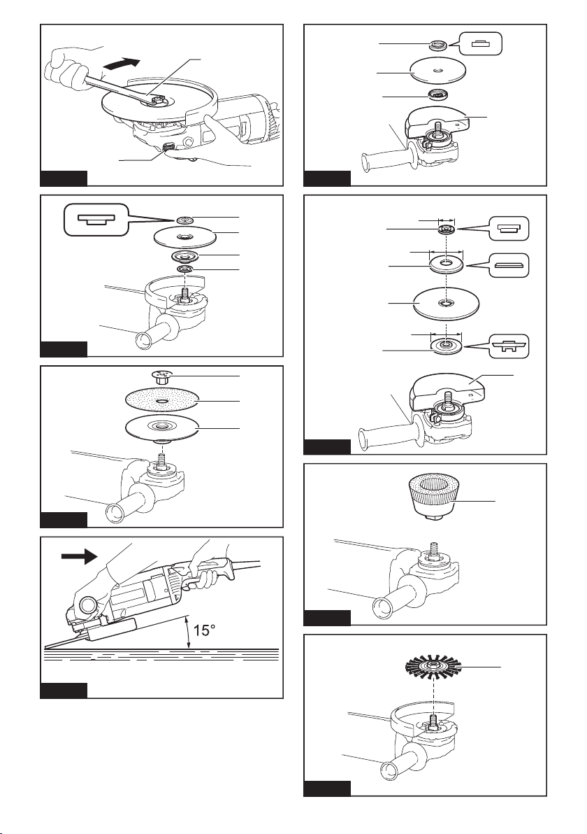
Fig.9
1
1
2
3
4
2
Fig.13
Fig.10
Fig.11
1
2
3
4
ø45
1
ø78
2
3
ø78
4
1
5
2
3
Fig.14
1
Fig.15
Fig.12
1
Fig.16
3
Page 4
1
2
3
5
4
Fig.17
Fig.19
2
Fig.18
1
1
6
3
8
5
6
7
8
10
11
12
13
2
14
9
5
4
Page 5

ENGLISH (Original instructions)
SPECIFICATIONS
Model: GA7061 GA7061R GA9061 GA9061R
Wheel diameter 180mm 230mm
Max. wheel thickness 6.5mm
Spindle thread M14 or M16 or 5/8″ (country specic)
Rated speed (n) 8,500min
Overall length 450mm
Net weight 5.5kg 5.7kg
Safety class
• Due to our continuing program of research and development, the specications herein are subject to change
without notice.
• Specications may differ from country to country.
• Weight according to EPTA-Procedure 01/2003
Intended use
The tool is intended for grinding, sanding and cutting of
metal and stone materials without the use of water.
Power supply
The tool should be connected only to a power supply of
the same voltage as indicated on the nameplate, and
can only be operated on single-phase AC supply. They
are double-insulated and can, therefore, also be used
from sockets without earth wire.
For public low-voltage distribution
systems of between 220 V and 250 V
Only for model GA7061 / GA9061
Switching operations of electric apparatus cause voltage uctuations. The operation of this device under
unfavorable mains conditions can have adverse effects
to the operation of other equipment. With a mains
impedance equal or less than 0.24 Ohms it can be presumed that there will be no negative effects. The mains
socket used for this device must be protected with a
fuse or protective circuit breaker having slow tripping
characteristics.
Noise
The typical A-weighted noise level determined according to EN60745:
Model GA7061
Sound pressure level (L
Sound power level (LWA) : 102 dB (A)
Uncertainty (K) : 3 dB(A)
Model GA7061R
Sound pressure level (L
Sound power level (LWA) : 102 dB (A)
Uncertainty (K) : 3 dB(A)
Model GA9061
Sound pressure level (L
Sound power level (LWA) : 102 dB (A)
Uncertainty (K) : 3dB(A)
) : 91 dB(A)
pA
) : 91 dB(A)
pA
) : 91 dB(A)
pA
-1
-1
6,600min
/II
Model GA9061R
Sound pressure level (L
Sound power level (LWA) : 102 dB (A)
) : 91 dB(A)
pA
Uncertainty (K) : 3dB(A)
WARNING: Wear ear protection.
Vibration
The vibration total value (tri-axial vector sum) determined according to EN60745:
Model GA7061
Work mode: surface grinding with normal side grip
Vibration emission (a
Uncertainty (K) : 1.5 m/s
) : 7.0 m/s
h, AG
2
Work mode: surface grinding with anti vibration side grip
Vibration emission (a
Uncertainty (K) : 1.5 m/s
) : 6.5 m/s
h, AG
2
Work mode: disc sanding with normal side grip
Vibration emission (a
Uncertainty (K) : 1.5 m/s
) : 2.5 m/s
h, DS
2
Work mode: disc sanding with anti vibration side grip
Vibration emission (a
Uncertainty (K) : 1.5 m/s
) : 2.5 m/s2 or less
h, AG
2
Model GA7061R
Work mode: surface grinding with normal side grip
Vibration emission (a
Uncertainty (K) : 1.5 m/s
) : 7.0 m/s
h, AG
2
Work mode: surface grinding with anti vibration side grip
Vibration emission (a
Uncertainty (K) : 1.5 m/s
) : 6.5 m/s
h, AG
2
Work mode: disc sanding with normal side grip
Vibration emission (a
Uncertainty (K) : 1.5 m/s
) : 2.5 m/s
h, DS
2
Work mode: disc sanding with anti vibration side grip
Vibration emission (a
Uncertainty (K) : 1.5 m/s
) : 2.5 m/s2 or less
h, AG
2
Model GA9061
Work mode: surface grinding with normal side grip
Vibration emission (a
Uncertainty (K) : 1.5 m/s
) : 6.5 m/s
h, AG
2
Work mode: surface grinding with anti vibration side grip
Vibration emission (a
Uncertainty (K) : 1.5 m/s
) : 5.5 m/s
h, AG
2
5 ENGLISH
2
2
2
2
2
2
2
2
Page 6

Work mode: disc sanding with normal side grip
Vibration emission (a
Uncertainty (K) : 1.5 m/s
) : 2.5 m/s2 or less
h, DS
2
Work mode: disc sanding with anti vibration side grip
Vibration emission (a
Uncertainty (K) : 1.5 m/s
) : 2.5 m/s2 or less
h, DS
2
Model GA9061R
Work mode: surface grinding with normal side grip
Vibration emission (a
Uncertainty (K) : 1.5 m/s
) : 6.5 m/s
h, AG
2
Work mode: surface grinding with anti vibration side grip
Vibration emission (a
Uncertainty (K) : 1.5 m/s
) : 5.5 m/s
h, AG
2
2
2
Work mode: disc sanding with normal side grip
Vibration emission (a
Uncertainty (K) : 1.5 m/s
) : 2.5 m/s2 or less
h, DS
2
Work mode: disc sanding with anti vibration side grip
Vibration emission (a
Uncertainty (K) : 1.5 m/s
) : 2.5 m/s2 or less
h, DS
2
NOTE: The declared vibration emission value has
been measured in accordance with the standard test
method and may be used for comparing one tool with
another.
NOTE: The declared vibration emission value
may also be used in a preliminary assessment of
exposure.
WARNING: The vibration emission during actual
use of the power tool can differ from the declared
emission value depending on the ways in which the
tool is used.
WARNING: Be sure to identify safety measures
to protect the operator that are based on an estimation of exposure in the actual conditions of use (taking
account of all parts of the operating cycle such as
the times when the tool is switched off and when it is
running idle in addition to the trigger time).
WARNING: The declared vibration emission
value is used for main applications of the power tool.
However if the power tool is used for other applications, the vibration emission value may be different.
EC Declaration of Conformity
For European countries only
Makita declares that the following Machine(s):
Designation of Machine: Angle Grinder
Model No./ Type: GA7061, GA7061R, GA9061,
GA9061R
Conforms to the following European Directives:
2006/42/EC
They are manufactured in accordance with the following
standard or standardized documents: EN60745
The technical le in accordance with 2006/42/EC is
available from:
Makita, Jan-Baptist Vinkstraat 2, 3070, Belgium
17.6.2015
Yasushi Fukaya
Director
Makita, Jan-Baptist Vinkstraat 2, 3070, Belgium
General power tool safety warnings
WARNING: Read all safety warnings and
all instructions. Failure to follow the warnings and
instructions may result in electric shock, re and/or
serious injury.
Save all warnings and instructions for future reference.
The term "power tool" in the warnings refers to your
mains-operated (corded) power tool or battery-operated
(cordless) power tool.
Grinder safety warnings
Safety Warnings Common for Grinding, Sanding,
Wire Brushing, or Abrasive Cutting-Off Operations:
1. This power tool is intended to function as a
grinder, sander, wire brush or cut-off tool.
Read all safety warnings, instructions, illus-
trations and specications provided with this
power tool. Failure to follow all instructions listed
below may result in electric shock, re and/or
serious injury.
2. Operations such as polishing are not recommended to be performed with this power
tool. Operations for which the power tool was not
designed may create a hazard and cause personal injury.
3. Do not use accessories which are not speci-
cally designed and recommended by the tool
manufacturer. Just because the accessory can
be attached to your power tool, it does not assure
safe operation.
4. The rated speed of the accessory must be at
least equal to the maximum speed marked on
the power tool. Accessories running faster than
their rated speed can break and y apart.
5. The outside diameter and the thickness of your
accessory must be within the capacity rating
of your power tool. Incorrectly sized accessories
cannot be adequately guarded or controlled.
6. Threaded mounting of accessories must
match the grinder spindle thread. For acces-
sories mounted by anges, the arbour hole of
the accessory must t the locating diameter
of the ange. Accessories that do not match the
mounting hardware of the power tool will run out of
balance, vibrate excessively and may cause loss
of control.
7. Do not use a damaged accessory. Before each
use inspect the accessory such as abrasive
wheels for chips and cracks, backing pad for
cracks, tear or excess wear, wire brush for
loose or cracked wires. If power tool or accessory is dropped, inspect for damage or install
an undamaged accessory. After inspecting and
installing an accessory, position yourself and
bystanders away from the plane of the rotating
accessory and run the power tool at maximum
no-load speed for one minute. Damaged acces-
sories will normally break apart during this test
time.
6 ENGLISH
Page 7

8. Wear personal protective equipment.
Depending on application, use face shield,
safety goggles or safety glasses. As appropriate, wear dust mask, hearing protectors,
gloves and workshop apron capable of stopping small abrasive or workpiece fragments.
The eye protection must be capable of stopping
ying debris generated by various operations.
The dust mask or respirator must be capable of
ltrating particles generated by your operation.
Prolonged exposure to high intensity noise may
cause hearing loss.
9. Keep bystanders a safe distance away from
work area. Anyone entering the work area
must wear personal protective equipment.
Fragments of workpiece or of a broken accessory
may y away and cause injury beyond immediate
area of operation.
10. Hold the power tool by insulated gripping
surfaces only, when performing an operation
where the cutting accessory may contact hidden wiring or its own cord. Cutting accessory
contacting a "live" wire may make exposed metal
parts of the power tool “live” and could give the
operator an electric shock.
11. Position the cord clear of the spinning acces-
sory. If you lose control, the cord may be cut or
snagged and your hand or arm may be pulled into
the spinning accessory.
12. Never lay the power tool down until the accessory has come to a complete stop. The spinning
accessory may grab the surface and pull the
power tool out of your control.
13. Do not run the power tool while carrying it at
your side. Accidental contact with the spinning
accessory could snag your clothing, pulling the
accessory into your body.
14. Regularly clean the power tool’s air vents. The
motor’s fan will draw the dust inside the housing
and excessive accumulation of powdered metal
may cause electrical hazards.
15. Do not operate the power tool near ammable
materials. Sparks could ignite these materials.
16. Do not use accessories that require liquid
coolants. Using water or other liquid coolants
may result in electrocution or shock.
Kickback and Related Warnings
Kickback is a sudden reaction to a pinched or snagged
rotating wheel, backing pad, brush or any other accessory. Pinching or snagging causes rapid stalling of the
rotating accessory which in turn causes the uncontrolled power tool to be forced in the direction opposite
of the accessory’s rotation at the point of the binding.
For example, if an abrasive wheel is snagged or
pinched by the workpiece, the edge of the wheel that is
entering into the pinch point can dig into the surface of
the material causing the wheel to climb out or kick out.
The wheel may either jump toward or away from the
operator, depending on direction of the wheel’s move-
ment at the point of pinching. Abrasive wheels may also
break under these conditions.
Kickback is the result of power tool misuse and/or
incorrect operating procedures or conditions and can be
avoided by taking proper precautions as given below.
1. Maintain a rm grip on the power tool and
position your body and arm to allow you to
resist kickback forces. Always use auxiliary
handle, if provided, for maximum control over
kickback or torque reaction during start-up.
The operator can control torque reactions or kickback forces, if proper precautions are taken.
2. Never place your hand near the rotating accessory. Accessory may kickback over your hand.
3. Do not position your body in the area where
power tool will move if kickback occurs.
Kickback will propel the tool in direction opposite
to the wheel’s movement at the point of snagging.
4. Use special care when working corners, sharp
edges etc. Avoid bouncing and snagging the
accessory. Corners, sharp edges or bouncing
have a tendency to snag the rotating accessory
and cause loss of control or kickback.
5. Do not attach a saw chain woodcarving blade
or toothed saw blade. Such blades create fre-
quent kickback and loss of control.
Safety Warnings Specic for Grinding and Abrasive
Cutting-Off Operations:
1. Use only wheel types that are recommended
for your power tool and the specic guard
designed for the selected wheel. Wheels for
which the power tool was not designed cannot be
adequately guarded and are unsafe.
2. The grinding surface of centre depressed
wheels must be mounted below the plane of
the guard lip. An improperly mounted wheel that
projects through the plane of the guard lip cannot
be adequately protected.
3. The guard must be securely attached to the
power tool and positioned for maximum safety,
so the least amount of wheel is exposed
towards the operator. The guard helps to protect
the operator from broken wheel fragments, accidental contact with wheel and sparks that could
ignite clothing.
4. Wheels must be used only for recommended
applications. For example: do not grind with
the side of cut-off wheel. Abrasive cut-off wheels
are intended for peripheral grinding, side forces
applied to these wheels may cause them to
shatter.
5. Always use undamaged wheel anges that are
of correct size and shape for your selected
wheel. Proper wheel anges support the wheel
thus reducing the possibility of wheel breakage.
Flanges for cut-off wheels may be different from
grinding wheel anges.
6. Do not use worn down wheels from larger
power tools. Wheel intended for larger power tool
is not suitable for the higher speed of a smaller
tool and may burst.
Additional Safety Warnings Specic for Abrasive
Cutting-Off Operations:
1. Do not “jam“ the cut-off wheel or apply excessive pressure. Do not attempt to make an
excessive depth of cut. Overstressing the wheel
increases the loading and susceptibility to twisting
or binding of the wheel in the cut and the possibility of kickback or wheel breakage.
7 ENGLISH
Page 8

2. Do not position your body in line with and
behind the rotating wheel. When the wheel, at
the point of operation, is moving away from your
body, the possible kickback may propel the spinning wheel and the power tool directly at you.
3. When wheel is binding or when interrupting
a cut for any reason, switch off the power
tool and hold the power tool motionless until
the wheel comes to a complete stop. Never
attempt to remove the cut-off wheel from the
cut while the wheel is in motion otherwise
kickback may occur. Investigate and take correc-
tive action to eliminate the cause of wheel binding.
4.
Do not restart the cutting operation in the workpiece. Let the wheel reach full speed and carefully
re-enter the cut. The wheel may bind, walk up or
kickback if the power tool is restarted in the workpiece.
5. Support panels or any oversized workpiece to
minimize the risk of wheel pinching and kickback. Large workpieces tend to sag under their
own weight. Supports must be placed under the
workpiece near the line of cut and near the edge
of the workpiece on both sides of the wheel.
6. Use extra caution when making a “pocket cut”
into existing walls or other blind areas. The
protruding wheel may cut gas or water pipes, electrical wiring or objects that can cause kickback.
Safety Warnings Specic for Sanding Operations:
1. Do not use excessively oversized sanding
disc paper. Follow manufacturers recommendations, when selecting sanding paper. Larger
sanding paper extending beyond the sanding
pad presents a laceration hazard and may cause
snagging, tearing of the disc or kickback.
Safety Warnings Specic for Wire Brushing
Operations:
1. Be aware that wire bristles are thrown by the
brush even during ordinary operation. Do not
overstress the wires by applying excessive
load to the brush. The wire bristles can easily
penetrate light clothing and/or skin.
2. If the use of a guard is recommended for wire
brushing, do not allow any interference of the
wire wheel or brush with the guard. Wire wheel
or brush may expand in diameter due to work load
and centrifugal forces.
Additional Safety Warnings:
1. When using depressed centre grinding wheels,
be sure to use only berglass-reinforced
wheels.
2. NEVER USE Stone Cup type wheels with this
grinder. This grinder is not designed for these
types of wheels and the use of such a product
may result in serious personal injury.
3. Be careful not to damage the spindle, the
ange (especially the installing surface) or the
lock nut. Damage to these parts could result in
wheel breakage.
4. Make sure the wheel is not contacting the
workpiece before the switch is turned on.
5. Before using the tool on an actual workpiece,
let it run for a while. Watch for vibration or
wobbling that could indicate poor installation
or a poorly balanced wheel.
6. Use the specied surface of the wheel to per-
form the grinding.
7. Do not leave the tool running. Operate the tool
only when hand-held.
8. Do not touch the workpiece immediately after
operation; it may be extremely hot and could
burn your skin.
9. Observe the instructions of the manufacturer
for correct mounting and use of wheels.
Handle and store wheels with care.
10. Do not use separate reducing bushings or
adaptors to adapt large hole abrasive wheels.
11. Use only anges specied for this tool.
12. For tools intended to be tted with threaded
hole wheel, ensure that the thread in the wheel
is long enough to accept the spindle length.
13. Check that the workpiece is properly
supported.
14. Pay attention that the wheel continues to
rotate after the tool is switched off.
15. If working place is extremely hot and humid,
or badly polluted by conductive dust, use a
short-circuit breaker (30 mA) to assure operator safety.
16. Do not use the tool on any materials containing asbestos.
17. When use cut-off wheel, always work with
the dust collecting wheel guard required by
domestic regulation.
18. Cutting discs must not be subjected to any
lateral pressure.
19. Do not use cloth work gloves during operation.
Fibers from cloth gloves may enter the tool, which
causes tool breakage.
SAVE THESE INSTRUCTIONS.
WARNING: DO NOT let comfort or familiarity
with product (gained from repeated use) replace
strict adherence to safety rules for the subject
product. MISUSE or failure to follow the safety
rules stated in this instruction manual may cause
serious personal injury.
FUNCTIONAL
DESCRIPTION
CAUTION: Always be sure that the tool is
switched off and unplugged before adjusting or
checking function on the tool.
CAUTION: Return the slide switch to the “O
(OFF)” position in case of accidental unplugging,
blackout, or the power is cut unintentionally.
Otherwise the tool may start suddenly when the
power returns and it may result in personal injury.
8 ENGLISH
Page 9
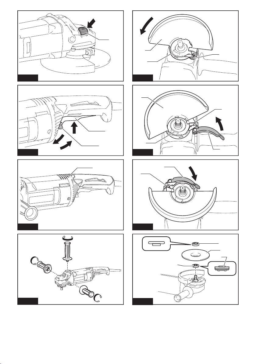
Shaft lock
Press the shaft lock to prevent spindle rotation when
installing or removing accessories.
► Fig.1: 1. Shaft lock
NOTICE: Never actuate the shaft lock when the
spindle is moving. The tool may be damaged.
Switch action
CAUTION: Before plugging in the tool, always
check to see that the switch trigger actuates
properly and returns to the "OFF" position when
released.
► Fig.2: 1. Switch trigger 2. Lock lever
For tool with the lock-on switch
CAUTION: Switch can be locked in "ON" posi-
tion for ease of operator comfort during extended
use. Apply caution when locking tool in "ON"
position and maintain rm grasp on tool.
To start the tool, simply pull the switch trigger (in the B
direction). Release the switch trigger to stop.
For continuous operation, pull the switch trigger (in the B
direction) and then push in the lock lever (in the A direction).
To stop the tool from the locked position, pull the switch
trigger fully (in the B direction), then release it.
Indication lamp
Only for model GA7061R / GA9061R
► Fig.3: 1. Indication lamp
The indication lamp lights up green when the tool is plugged.
If the indication lamp does not light up, the mains cord
or the controller may be defective.
The indication lamp is lit but the tool does not start even
if the tool is switched on, the carbon brushes may be
worn out, or the controller, the motor or the ON/OFF
switch may be defective.
Unintentional restart proof
The tool does not start with the switch being lock-on
even when the tool is plugged.
At this time, the indication lamp ickers red and shows
the unintentional restart proof device is on function.
To cancel the unintentional restart proof, return the
power switch to OFF position.
NOTE: Wait more than one second before restarting
the tool when unintentional restart proof functions.
Soft start feature
Soft start feature reduces starting reaction.
ASSEMBLY
For tool with the lock-off switch
To prevent the switch trigger from accidentally pulled, a
lock lever is provided.
To start the tool, push in the lock lever (in the A direction) and then pull the switch trigger (in the B direction).
Release the switch trigger to stop.
NOTICE: Do not pull the switch trigger hard
without pressing in the lock-off button. This can
cause switch breakage.
For tool with the lock-on and lock-off
switch
CAUTION: Switch can be locked in "ON" posi-
tion for ease of operator comfort during extended
use. Apply caution when locking tool in "ON"
position and maintain rm grasp on tool.
To prevent the switch trigger from accidentally pulled, a
lock lever is provided.
To start the tool, push in the lock lever (in the A direction) and then pull the switch trigger (in the B direction).
Release the switch trigger to stop.
For continuous operation, push in the lock lever (in the
A direction), pull the switch trigger (in the B direction)
and then pull the lock lever (in the C direction).
To stop the tool from the locked position, pull the switch
trigger fully (in the B direction), then release it.
NOTICE: Do not pull the switch trigger hard
without pressing in the lock-off button. This can
cause switch breakage.
CAUTION: Always be sure that the tool is
switched off and unplugged before carrying out
any work on the tool.
Installing side grip (handle)
CAUTION: Always be sure that the side grip is
installed securely before operation.
Screw the side grip securely on the position of the tool
as shown in the gure.
► Fig.4
Installing or removing wheel guard
(For depressed center wheel, ap
disc, ex wheel, wire wheel brush
/ abrasive cut-off wheel, diamond
wheel)
WARNING: When using a depressed center
wheel, ap disc, ex wheel or wire wheel brush,
the wheel guard must be tted on the tool so that
the closed side of the guard always points toward
the operator.
WARNING: When using an abrasive cut-off
/ diamond wheel, be sure to use only the special
wheel guard designed for use with cut-off wheels.
(In some European countries, when using a diamond
wheel, the ordinary guard can be used. Follow the
regulations in your country.)
9 ENGLISH
Page 10
For tool with locking screw type
wheel guard
Mount the wheel guard with the protrusions on the
wheel guard band aligned with the notches on the bearing box. Then rotate the wheel guard to such an angle
that it can protect the operator according to work. Be
sure to tighten the screw securely.
To remove wheel guard, follow the installation procedure in reverse.
► Fig.5: 1. Wheel guard 2. Bearing box 3. Screw
For tool with clamp lever type wheel
guard
Loosen the screw, and then pull the lever in the direction of the arrow. Mount the wheel guard with the protrusions on the wheel guard band aligned with the notches
on the bearing box. Then rotate the wheel guard to such
an angle that it can protect the operator according to
work.
► Fig.6: 1. Wheel guard 2. Bearing box 3. Screw
4. Lever
Pull the lever in direction of the arrow. Then tighten the
wheel guard with fastening the screw. Be sure to tighten
the screw securely. The setting angle of the wheel
guard can be adjusted with the lever.
► Fig.7: 1. Screw 2. Lever
To remove wheel guard, follow the installation procedure in reverse.
Installing or removing depressed
center wheel or ap disc
Optional accessory
WARNING: When using a depressed center
wheel or ap disc, the wheel guard must be tted
on the tool so that the closed side of the guard
always points toward the operator.
WARNING: Never use a grinding wheel which
is more than 6.5 mm thick.
CAUTION: Make sure that the mounting part
of the inner ange ts into the inner diameter of
the depressed center wheel / ap disc perfectly.
Mounting the inner ange on the wrong side may
result in the dangerous vibration.
Mount the inner ange onto the spindle.
Make sure to t the dented part of the inner ange onto
the straight part at the bottom of the spindle.
Fit the wheel/ disc on the inner ange and screw the
lock nut with its protrusion facing downward (facing
towards the wheel).
► Fig.8: 1. Lock nut 2. Depressed center wheel
3. Inner ange 4. Mounting part
To tighten the lock nut, press the shaft lock rmly so
that the spindle cannot revolve, then use the lock nut
wrench and securely tighten clockwise.
► Fig.9: 1. Lock nut wrench 2. Shaft lock
To remove the wheel, follow the installation procedure
in reverse.
Installing or removing ex wheel
Optional accessory
WARNING: Always use supplied guard when
ex wheel is on tool. Wheel can shatter during use
and guard helps to reduce chances of personal injury.
► Fig.10: 1. Lock nut 2. Flex wheel 3. Back up pad
4. Inner ange
Follow instructions for depressed center wheel but also
use back up pad over wheel. See order of assembly on
accessories page in this manual.
Super ange
Optional accessory
Only for tools with M14 spindle thread.
Models with the letter F are standard-equipped with
Super ange. Only 1/3 of efforts needed to undo lock
nut, compared with conventional type.
Installing or removing abrasive disc
Optional accessory
► Fig.11: 1. Sanding lock nut 2. Abrasive disc
3. Rubber pad
1. Mount the rubber pad onto the spindle.
2. Fit the disc on the rubber pad and screw the sand-
ing lock nut onto the spindle.
3. Hold the spindle with the shaft lock, and securely
tighten the sanding lock nut clockwise with the lock nut
wrench.
To remove the disc, follow the installation procedure in
reverse.
NOTE: Use sander accessories specied in this manual. These must be purchased separately.
OPERATION
WARNING: It should never be necessary to
force the tool. The weight of the tool applies ade-
quate pressure. Forcing and excessive pressure
could cause dangerous wheel breakage.
WARNING: ALWAYS replace wheel if tool is
dropped while grinding.
WARNING: NEVER bang or hit grinding disc
or wheel onto work.
WARNING: Avoid bouncing and snagging
the wheel, especially when working corners,
sharp edges etc. This can cause loss of control and
kickback.
WARNING: NEVER use tool with wood cutting
blades and other saw blades. Such blades when
used on a grinder frequently kick and cause loss of
control leading to personal injury.
10 ENGLISH
Page 11

CAUTION: Never switch on the tool when it
is in contact with the workpiece, it may cause an
injury to operator.
CAUTION: Always wear safety goggles or a
face shield during operation.
CAUTION: After operation, always switch off
the tool and wait until the wheel has come to a
complete stop before putting the tool down.
CAUTION: ALWAYS hold the tool rmly with
one hand on housing and the other on the side
handle.
Grinding and sanding operation
► Fig.12
Turn the tool on and then apply the wheel or disc to the
workpiece.
In general, keep the edge of the wheel or disc at an
angle of about 15° to the workpiece surface.
During the break-in period with a new wheel, do not
work the grinder in forward direction or it may cut into
the workpiece. Once the edge of the wheel has been
rounded off by use, the wheel may be worked in both
forward and backward direction.
Operation with abrasive cut-off /
diamond wheel
Optional accessory
WARNING: When using an abrasive cut-off
/ diamond wheel, be sure to use only the special
wheel guard designed for use with cut-off wheels.
(In some European countries, when using a diamond
wheel, the ordinary guard can be used. Follow the
regulations in your country.)
WARNING: NEVER use cut-off wheel for side
grinding.
WARNING: Do not "jam" the wheel or apply
excessive pressure. Do not attempt to make an
excessive depth of cut. Overstressing the wheel
increases the loading and susceptibility to twisting
or binding of the wheel in the cut and the possibility
of kickback, wheel breakage and overheating of the
motor may occur.
WARNING: Do not start the cutting operation
in the workpiece. Let the wheel reach full speed
and carefully enter into the cut moving the tool
forward over the workpiece surface. The wheel
may bind, walk up or kickback if the power tool is
started in the workpiece.
WARNING:
change the angle of the wheel. Placing side pressure
on the cut-off wheel (as in grinding) will cause the wheel
to crack and break, causing serious personal injury.
WARNING: A diamond wheel shall be oper-
ated perpendicular to the material being cut.
Mount the inner ange onto the spindle.
Fit the wheel / disc on the inner ange and screw the
lock nut onto the spindle.
During cutting operations, never
► Fig.13: 1. Lock nut 2. Abrasive cut-off wheel / dia-
mond wheel 3. Inner ange 4. Wheel guard
for abrasive cut-off wheel / diamond wheel
For Australia and New Zealand
► Fig.14: 1. Lock nut 2. Outer ange 78 3. Abrasive
cut-off wheel / diamond wheel 4. Inner
ange 78 5. Wheel guard for abrasive cut-
off wheel / diamond wheel
Operation with wire cup brush
Optional accessory
CAUTION: Check operation of brush by run-
ning tool with no load, insuring that no one is in
front of or in line with brush.
CAUTION: Do not use brush that is damaged,
or which is out of balance. Use of damaged brush
could increase potential for injury from contact with
broken brush wires.
► Fig.15: 1. Wire cup brush
Unplug tool and place it upside down allowing easy
access to spindle.
Remove any accessories on spindle. Thread wire cup
brush onto spindle and tighten with supplied wrench.
NOTICE: Avoid applying too much pressure
which causes over bending of wires when using
brush. It may lead to premature breakage.
Operation with wire wheel brush
Optional accessory
CAUTION: Check operation of wire wheel
brush by running tool with no load, insuring that
no one is in front of or in line with the wire wheel
brush.
CAUTION: Do not use wire wheel brush that
is damaged, or which is out of balance. Use of
damaged wire wheel brush could increase potential
for injury from contact with broken wires.
CAUTION: ALWAYS use guard with wire
wheel brushes, assuring diameter of wheel ts
inside guard. Wheel can shatter during use and
guard helps to reduce chances of personal injury.
► Fig.16: 1. Wire wheel brush
Unplug tool and place it upside down allowing easy
access to spindle.
Remove any accessories on spindle. Thread wire wheel
brush onto spindle and tighten with the wrenches.
NOTICE: Avoid applying too much pressure
which causes over bending of wires when
using wire wheel brush. It may lead to premature
breakage.
11 ENGLISH
Page 12

MAINTENANCE
CAUTION: Always be sure that the tool is
switched off and unplugged before attempting to
perform inspection or maintenance.
NOTICE: Never use gasoline, benzine, thinner,
alcohol or the like. Discoloration, deformation or
cracks may result.
► Fig.17: 1. Exhaust vent 2. Inhalation vent
NOTE: Do not loosen the screw on the name
plate cover. Otherwise the cover may be opened
accidentally.
► Fig.18: 1. Screw
To maintain product SAFETY and RELIABILITY,
repairs, any other maintenance or adjustment should
be performed by Makita Authorized or Factory Service
Centers, always using Makita replacement parts.
Air vent cleaning
The tool and its air vents have to be kept clean.
Regularly clean the tool's air vents or whenever the
vents start to become obstructed.
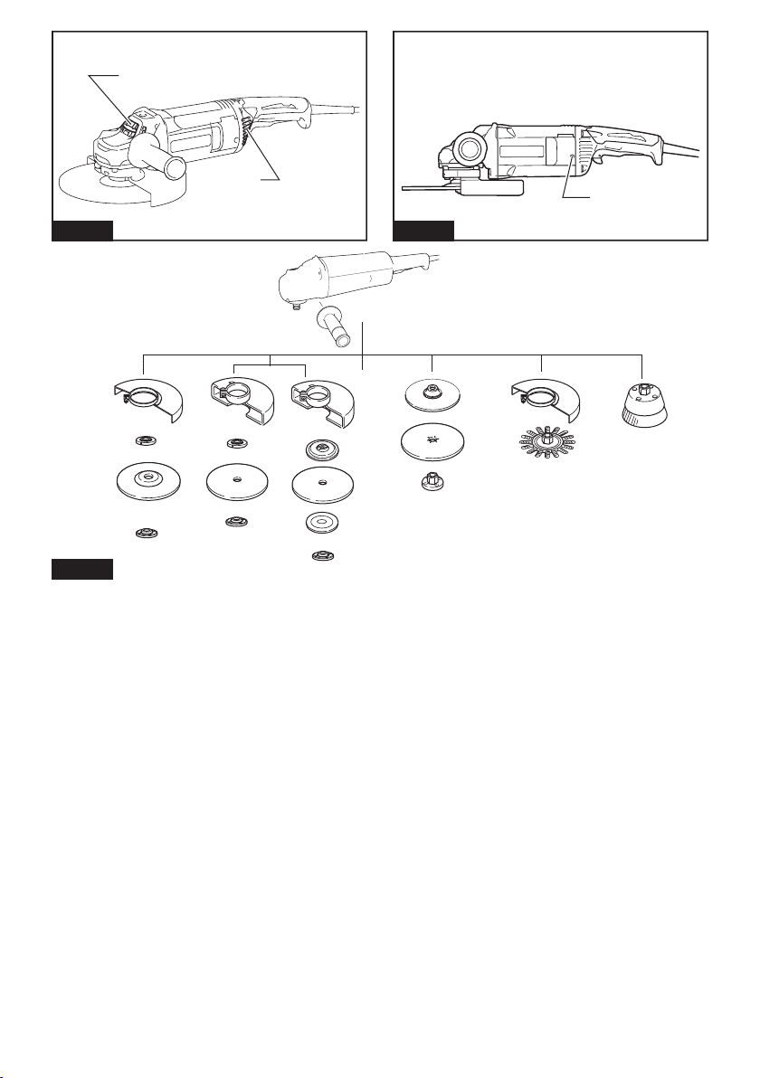
OPTIONAL ACCESSORIES
CAUTION: These accessories or attachments are recommended for use with your Makita tool spec-
ied in this manual. The use of any other accessories or attachments might present a risk of injury to persons.
Only use accessory or attachment for its stated purpose.
If you need any assistance for more details regarding these accessories, ask your local Makita Service Center.
► Fig.19
1 Side grip
2 Wheel guard for depressed center grinding wheel / ap disc / wire wheel brush
3 Inner ange / Super ange *1*2
4 Depressed center grinding wheel / Flap disc
5 Lock nut / Ezynut *1*2
6 Wheel guard for abrasive cut off wheel / diamond wheel *3
7 Inner ange 78 (Australia and New Zealand only) *4
8 Abrasive cut-off wheel / Diamond wheel
9 Outer ange 78 (Australia and New Zealand only) *4
10 Rubber pad
11 Abrasive disc
12 Sanding lock nut
13 Wire wheel brush
14 Wire cup brush
- Lock nut wrench
- Dust cover attachment
NOTE: *1 Only for tools with M14 spindle thread.
NOTE: *2 Do not use Super ange and Ezynut together.
NOTE: *3 In some European countries, when using a diamond wheel, the ordinary guard can be used instead of the
special guard covering the both side of the wheel. Follow the regulations in your country.
NOTE: *4 Use Inner ange 78 and Outer ange 78 together. (Australia and New Zealand only)
NOTE: Some items in the list may be included in the tool package as standard accessories. They may differ from
country to country.
12 ENGLISH
Page 13

FRANÇAIS (Instructions originales)
SPÉCIFICATIONS
Modèle : GA7061 GA7061R GA9061 GA9061R
Diamètre de meule 180 mm 230 mm
Épaisseur max. de la
meule
Filetage de l’axe M14 ou M16 ou 5/8″ (selon le pays)
Vitesse nominale (n) 8 500 min
Longueur totale 450 mm
Poids net 5,5 kg 5,7 kg
Catégorie de sécurité
-1
• Étant donné l’évolution constante de notre programme de recherche et de développement, les spécications
contenues dans ce manuel sont sujettes à modication sans préavis.
• Les spécications peuvent varier suivant les pays.
• Poids selon la procédure EPTA 01/2003
Utilisations
L’outil est conçu pour le meulage, le ponçage et la
coupe de matériaux en métal ou en pierre sans utiliser
d’eau.
Alimentation
L’outil ne devra être raccordé qu’à une alimentation de
la même tension que celle qui gure sur la plaque signalétique, et il ne pourra fonctionner que sur un courant
secteur monophasé. Réalisé avec une double isolation,
il peut de ce fait être alimenté par une prise sans mise à
la terre.
Pour les systèmes de distribution
publics à basse tension, entre 220 V
et 250 V
Uniquement pour le modèle GA7061/GA9061
La mise sous tension et hors tension des appareils électriques entraîne des uctuations de tension. L’utilisation
de cet appareil dans des conditions d’alimentation électrique inadéquates peut avoir des effets néfastes sur le
fonctionnement des autres équipements. Il ne devrait
toutefois pas y avoir d’effets négatifs si l’impédance
de l’alimentation est égale ou inférieure à 0,24 ohm.
La prise de courant utilisée pour cet appareil doit être
protégée par un fusible ou un disjoncteur de protection
à déclenchement lent.
Bruit
Niveau de bruit pondéré A typique, déterminé selon
EN60745 :
Modèle GA7061
Niveau de pression sonore (L
Niveau de puissance sonore (L
Incertitude (K) : 3 dB (A)
) : 91 dB (A)
pA
) : 102 dB (A)
WA
6,5 mm
-1
6 600 min
/II
Modèle GA7061R
Niveau de pression sonore (L
Niveau de puissance sonore (L
Incertitude (K) : 3 dB (A)
) : 91 dB (A)
pA
) : 102 dB (A)
WA
Modèle GA9061
Niveau de pression sonore (L
Niveau de puissance sonore (L
Incertitude (K) : 3 dB (A)
) : 91 dB (A)
pA
) : 102 dB (A)
WA
Modèle GA9061R
Niveau de pression sonore (L
Niveau de puissance sonore (L
Incertitude (K) : 3 dB (A)
) : 91 dB (A)
pA
) : 102 dB (A)
WA
AVERTISSEMENT : Portez un serre-tête
antibruit.
Vibrations
Valeur totale de vibrations (somme de vecteur triaxial)
déterminée selon EN60745 :
Modèle GA7061
Mode de travail : meulage de surfaces avec poignée
latérale normale
Émission de vibrations (a
Incertitude (K) : 1,5 m/s
h, AG
2
) : 7,0 m/s
Mode de travail : meulage de surfaces avec poignée
latérale anti-vibration
Émission de vibrations (a
Incertitude (K) : 1,5 m/s
h, AG
2
) : 6,5 m/s
Mode de travail : ponçage au disque avec poignée
latérale normale
Émission de vibrations (a
Incertitude (K) : 1,5 m/s
h, DS
2
) : 2,5 m/s
Mode de travail : ponçage au disque avec poignée
latérale anti-vibration
Émission de vibrations (a
Incertitude (K) : 1,5 m/s
) : 2,5 m/s2 ou moins
h, AG
2
Modèle GA7061R
Mode de travail : meulage de surfaces avec poignée
latérale normale
Émission de vibrations (a
Incertitude (K) : 1,5 m/s
h, AG
2
) : 7,0 m/s
2
2
2
2
13 FRANÇAIS
Page 14

Mode de travail : meulage de surfaces avec poignée
latérale anti-vibration
Émission de vibrations (a
Incertitude (K) : 1,5 m/s
h, AG
2
) : 6,5 m/s
2
Mode de travail : ponçage au disque avec poignée
latérale normale
Émission de vibrations (a
Incertitude (K) : 1,5 m/s
h, DS
2
) : 2,5 m/s
2
Mode de travail : ponçage au disque avec poignée
latérale anti-vibration
Émission de vibrations (a
Incertitude (K) : 1,5 m/s
) : 2,5 m/s2 ou moins
h, AG
2
Modèle GA9061
Mode de travail : meulage de surfaces avec poignée
latérale normale
Émission de vibrations (a
Incertitude (K) : 1,5 m/s
h, AG
2
) : 6,5 m/s
2
Mode de travail : meulage de surfaces avec poignée
latérale anti-vibration
Émission de vibrations (a
Incertitude (K) : 1,5 m/s
h, AG
2
) : 5,5 m/s
2
Mode de travail : ponçage au disque avec poignée
latérale normale
Émission de vibrations (a
Incertitude (K) : 1,5 m/s
) : 2,5 m/s2 ou moins
h, DS
2
Mode de travail : ponçage au disque avec poignée
latérale anti-vibration
Émission de vibrations (a
Incertitude (K) : 1,5 m/s
) : 2,5 m/s2 ou moins
h, DS
2
Modèle GA9061R
Mode de travail : meulage de surfaces avec poignée
latérale normale
Émission de vibrations (a
Incertitude (K) : 1,5 m/s
h, AG
2
) : 6,5 m/s
2
Mode de travail : meulage de surfaces avec poignée
latérale anti-vibration
Émission de vibrations (a
Incertitude (K) : 1,5 m/s
h, AG
2
) : 5,5 m/s
2
Mode de travail : ponçage au disque avec poignée
latérale normale
Émission de vibrations (a
Incertitude (K) : 1,5 m/s
) : 2,5 m/s2 ou moins
h, DS
2
Mode de travail : ponçage au disque avec poignée
latérale anti-vibration
Émission de vibrations (a
Incertitude (K) : 1,5 m/s
) : 2,5 m/s2 ou moins
h, DS
2
NOTE : La valeur d’émission de vibrations déclarée
a été mesurée conformément à la méthode de test
standard et peut être utilisée pour comparer les outils
entre eux.
NOTE : La valeur d’émission de vibrations déclarée
peut aussi être utilisée pour l’évaluation préliminaire
de l’exposition.
AVERTISSEMENT : L’émission de vibrations
lors de l’usage réel de l’outil électrique peut être
différente de la valeur d’émission déclarée, suivant la
façon dont l’outil est utilisé.
AVERTISSEMENT : Les mesures de sécurité à
prendre pour protéger l’utilisateur doivent être basées
sur une estimation de l’exposition dans des conditions réelles d’utilisation (en tenant compte de toutes
les composantes du cycle d’utilisation, comme par
exemple le moment de sa mise hors tension, lorsqu’il
tourne à vide et le moment de son déclenchement).
AVERTISSEMENT : La valeur d’émission de
vibrations déclarée est utilisée pour les applications
principales de l’outil électrique. Toutefois si l’outil
électrique est utilisé pour d’autres applications, la
valeur d’émission de vibrations peut être différente.
Déclaration de conformité CE
Pour les pays européens uniquement
Makita déclare que la ou les machines suivantes :
Désignation de la machine : Meuleuse d’Angle
N° de modèle/Type : GA7061, GA7061R, GA9061,
GA9061R
sont conformes aux Directives européennes suivantes :
2006/42/CE
et sont fabriquées conformément aux normes ou aux
documents normalisés suivants : EN60745
La documentation technique conforme à la norme
2006/42/CE est disponible auprès de :
Makita, Jan-Baptist Vinkstraat 2, 3070, Belgique
17.6.2015
Yasushi Fukaya
Directeur
Makita, Jan-Baptist Vinkstraat 2, 3070, Belgique
Consignes de sécurité générales
pour outils électriques
AVERTISSEMENT : Lisez toutes les
consignes de sécurité et toutes les instructions. Il
y a risque d’électrocution, d’incendie et/ou de graves
blessures si les mises en garde et les instructions ne
sont pas respectées.
Conservez toutes les mises en
garde et instructions pour référence ultérieure.
Le terme « outil électrique » dans les avertissements
fait référence à l’outil électrique alimenté par le secteur
(avec cordon d’alimentation) ou à l’outil électrique fonctionnant sur batterie (sans cordon d’alimentation).
14 FRANÇAIS
Page 15

Consignes de sécurité pour
meuleuse
Consignes de sécurité communes aux travaux de
meulage, ponçage, brossage métallique ou tronçonnage abrasif :
1. Cet outil électrique est conçu pour être utilisé en tant que meuleuse, ponceuse, brosse
métallique ou outil de tronçonnage. Veuillez
lire les consignes de sécurité, instructions,
illustrations et spécications qui accompagnent cet outil électrique. Le non-respect de
toutes les instructions indiquées ci-dessous peut
entraîner une électrocution, un incendie et/ou de
graves blessures.
2. Il est déconseillé d’effectuer des travaux de
polissage avec cet outil électrique. Il y a risque
de danger et de blessure si l’outil électrique est
utilisé pour exécuter des travaux pour lesquels il
n’a pas été conçu.
3. N’utilisez pas d’accessoires qui n’ont pas été
conçus spéciquement et recommandés par le
fabricant de l’outil. Même si un accessoire peut
être xé sur l’outil électrique, cela ne garantit pas
qu’il fonctionnera de manière sûre.
4. La vitesse nominale de l’accessoire doit être
au moins égale à la vitesse maximum inscrite
sur l’outil électrique. Les accessoires tournant
plus vite que leur vitesse nominale peuvent se
casser et voler en éclats.
5. Le diamètre extérieur et l’épaisseur de l’accessoire ne doivent pas dépasser la capacité
nominale de l’outil électrique. Les accessoires
de taille incorrecte ne peuvent être protégés ou
contrôlés adéquatement.
6. Le letage des accessoires à monter doit
correspondre à celui de l’axe de la meuleuse.
Pour les accessoires montés à l’aide de
asques, la taille de l’alésage de l’accessoire
doit correspondre au diamètre du asque.
Les accessoires qui ne sont pas bien adaptés à
la taille de la pièce où ils sont montés sur l’outil
électrique se déséquilibreront, vibreront trop et
pourront entraîner une perte de maîtrise de l’outil.
7. N’utilisez jamais un accessoire endommagé.
Avant chaque utilisation, assurez-vous que
la meule abrasive est exempte de copeaux et
ssures, que la semelle n’est pas ssurée,
déchirée ou trop usée, ou que la brosse métal-
lique est exempte de ls métalliques lâches
ou cassés. Si vous lâchez l’outil électrique ou
un accessoire, assurez-vous qu’il n’est pas
endommagé ou bien remplacez l’accessoire
endommagé. Après avoir vérié et posé un
accessoire, assurez-vous que personne, y
compris vous-même, ne se trouve dans la
trajectoire de l’accessoire en rotation et faites
tourner l’outil électrique à vitesse à vide maximale pendant une minute. Les accessoires
endommagés se brisent généralement au cours
de cette période d’essai.
8. Portez un équipement de protection individuelle. Suivant le type de travail à effectuer,
utilisez un écran facial, des lunettes à coques
ou des lunettes de sécurité. Si nécessaire,
portez un masque anti-poussière, des protège-tympans, des gants et un tablier de travail
pouvant arrêter les particules abrasives ou les
fragments de pièce. La protection oculaire doit
pouvoir arrêter les débris volants produits par les
diverses opérations. Le masque anti-poussières
ou le masque ltrant doit pouvoir ltrer les particules générées lors des travaux. Une exposition
prolongée à un bruit d’intensité élevée peut entraîner une perte auditive.
9. Assurez-vous que les passants demeurent à
une distance sûre de la zone de travail. Toute
personne pénétrant dans la zone de travail
doit porter un équipement de protection individuelle. Des fragments de pièce ou un accessoire
cassé peuvent être éjectés et blesser les personnes au-delà de la zone immédiate de travail.
10. Tenez l’outil électrique par une surface de
prise isolée uniquement, lorsque vous effec-
tuez une tâche où l’accessoire de coupe pourrait toucher un câblage caché ou son propre
cordon d’alimentation. Le contact de l’accessoire de coupe avec un l sous tension peut transmettre du courant dans les pièces métalliques
exposées de l’outil électrique et électrocuter
l’utilisateur.
11. Placez le cordon à l’écart de l’accessoire
en rotation. En cas de perte de maîtrise, vous
risquez, en coupant ou en accrochant le cordon,
d’avoir la main ou le bras attiré vers l’accessoire
en rotation.
12. Ne déposez jamais l’outil électrique avant que
l’accessoire ne se soit parfaitement arrêté.
L’accessoire en rotation peut accrocher la surface
et projeter l’outil électrique de telle sorte que vous
en perdiez la maîtrise.
13. Ne transportez pas l’outil électrique tout en le
laissant tourner. En cas de contact accidentel
avec l’accessoire en rotation, ce dernier risque
d’accrocher vos vêtements et d’être entraîné vers
votre corps.
14. Nettoyez régulièrement les orices d’aération
de l’outil électrique. Le ventilateur du moteur
aspire la poussière à l’intérieur du carter, ce qui
présente un danger électrique en cas d’accumulation excessive de poussières métalliques.
15. N’utilisez pas l’outil électrique près de maté-
riaux inammables. Les étincelles risqueraient
d’enammer ces matériaux.
16. N’utilisez pas d’accessoires nécessitant un
liquide de refroidissement. L’utilisation d’eau
ou d’un liquide de refroidissement comporte un
risque d’électrocution ou de choc électrique.
Mises en garde concernant le choc en retour et
autres dangers
Le choc en retour est une réaction soudaine qui survient lorsque la meule, la semelle, la brosse ou un autre
accessoire en rotation se coince ou accroche. Lorsque
l’accessoire en rotation se coince ou accroche, il s’arrête soudainement et l’utilisateur perd alors la maîtrise
de l’outil électrique projeté dans le sens contraire de sa
rotation au point où il se coince dans la pièce.
Par exemple, si une meule abrasive accroche ou se
coince dans la pièce, son tranchant introduit au point
de pincement risque d’y creuser la surface du matériau,
entraînant la sortie ou le déchaussement de la meule.
15 FRANÇAIS
Page 16

La meule peut alors dévier de sa trajectoire, vers l’utilisateur ou dans le sens opposé, selon la direction du
mouvement de la meule au point de pincement. Dans
ces conditions, la meule abrasive risque également de
se briser.
Le choc en retour est le résultat d’une utilisation
incorrecte de l’outil électrique et/ou de l’inobservation
des procédures ou conditions d’utilisation. Il peut être
évité en prenant les précautions adéquates indiquées
ci-dessous.
1. Maintenez une poigne ferme sur l’outil électrique et placez corps et bras de façon à pouvoir résister à la force exercée par les chocs
en retour. Utilisez toujours la poignée auxiliaire, s’il y en a une, pour avoir une maîtrise
maximale de l’outil en cas de choc en retour
ou de force de réaction exercée au moment du
démarrage. L’utilisateur peut maîtriser les forces
de réaction ou de choc en retour s’il prend les
précautions adéquates.
2. Ne placez jamais la main près d’un accessoire
en rotation. L’accessoire risquerait de passer sur
votre main en cas de choc en retour.
3. Ne vous placez pas dans la zone vers laquelle
l’outil électrique se déplacera en cas de choc
en retour. Le choc en retour projettera l’outil dans
le sens opposé au mouvement de la meule au
point où elle accroche dans la pièce.
4. Soyez tout particulièrement prudent lorsque
vous travaillez sur les coins, les arêtes vives,
etc. Évitez de laisser l’accessoire sautiller ou
accrocher. L’accessoire en rotation a tendance
à accrocher dans les coins, sur les arêtes vives
ou lorsqu’il sautille, ce qui comporte un risque de
perte de maîtrise ou de choc en retour.
5. Ne xez pas une chaîne de coupe, une lame à
sculpter le bois ou une lame de scie dentée. De
telles lames causent fréquemment des chocs en
retour et des pertes de maîtrise.
Consignes de sécurité spéciques aux opérations
de meulage et de tronçonnage abrasif :
1. Utilisez exclusivement les types de meule
recommandés pour votre outil électrique, et
le carter de protection conçu spéciquement
pour la meule sélectionnée. Les meules pour
lesquelles l’outil électrique n’a pas été conçu ne
pourront pas être protégées correctement et se
révèleront dangereuses.
2. La surface de meulage des meules à moyeu
déporté doit être montée sous le plan de la
lèvre du carter de protection. Si la meule n’est
pas bien montée et dépasse le plan de la lèvre du
carter de protection, celui-ci ne pourra pas assurer
une protection adéquate.
3. Le carter de protection doit être solidement
xé à l’outil électrique et placé de façon à
assurer une sécurité maximale en ne laissant
qu’une partie minimale de la meule exposée
du côté de l’utilisateur. Le carter de protection
permet de protéger l’utilisateur des éclats de
meule brisée, d’un contact accidentel avec la
meule et des étincelles qui pourraient enammer
ses vêtements.
4. Les meules ne doivent être utilisées que pour
les applications recommandées. Par exemple
: ne procédez pas au meulage avec le côté de
la meule à tronçonner. Les meules à tronçonner
abrasives étant conçues pour le meulage périphérique, elles risquent de voler en éclats si on leur
applique une force latérale.
5. Utilisez toujours des asques pour meule
en bon état, dont la taille et la forme correspondent à la meule sélectionnée. Des asques
pour meule adéquats soutiennent la meule et
réduisent ainsi les risques de rupture de la meule.
Les asques pour meules à tronçonner peuvent
être différents de ceux pour meules ordinaires.
6. N’utilisez pas de meules usées provenant
d’outils électriques plus grands. Les meules
conçues pour des outils électriques plus grands
ne conviennent pas à la vitesse supérieure d’un
outil plus petit et risquent d’éclater.
Consignes de sécurité supplémentaires spéciques
aux travaux de tronçonnage abrasif :
1. Évitez de « bloquer » la meule à tronçonner ou
d’appliquer une pression excessive. N’essayez
pas de couper trop profondément. Une meule
trop sollicitée subira une surcharge et risquera de
se tordre ou de se coincer dans la ligne de coupe,
ce qui comporte un risque de choc en retour ou de
bris de la meule.
2. Ne vous placez pas directement derrière ou
devant la meule en rotation. Lorsque la meule,
en cours de fonctionnement, s’écarte de votre
corps, le choc en retour potentiel risque de propulser la meule en rotation et l’outil électrique dans
votre direction.
3. Lorsque la meule se coince ou lorsque vous
interrompez la coupe pour une raison quelconque, mettez l’outil électrique hors tension
et maintenez-le immobile jusqu’à ce que la
meule cesse complètement de tourner. Ne
tentez jamais de retirer la meule à tronçonner
de la coupe pendant que la meule tourne,
sous peine de provoquer un choc en retour.
Identiez la cause du grippage de la meule et
prenez les mesures correctives pour y remédier.
4. Ne reprenez pas la coupe telle quelle dans
la pièce. Attendez que la meule ait atteint sa
pleine vitesse avant de la réintroduire soigneusement dans la ligne de coupe. Si vous
redémarrez l’outil électrique alors qu’il se trouve
encore dans la pièce à travailler, la meule risquera
de se coincer, de remonter hors de la ligne de
coupe ou de provoquer un choc en retour.
5. Soutenez les panneaux ou les pièces de
grande taille pour réduire les risques de coincement de la meule et de choc en retour. Les
pièces de grande taille ont tendance à ployer
sous leur propre poids. Il est nécessaire de placer
en dessous des cales à proximité de la ligne de
coupe et près du rebord de la pièce de chaque
côté de la meule.
6. Redoublez de précaution lorsque vous faites
une « coupe en plongée » dans un mur ou
toute autre surface pouvant cacher des structures. La meule, en dépassant derrière le mur ou
la surface, peut couper des conduites de gaz ou
d’eau, des ls électriques ou des objets pouvant
causer un choc en retour.
16 FRANÇAIS
Page 17

Consignes de sécurité spéciques aux travaux de
ponçage :
1. N’utilisez pas de feuilles de papier abrasif
trop grandes. Suivez les recommandations du
fabricant pour choisir le papier abrasif. Une
grande feuille de papier abrasif débordant du
coussin de ponçage présente un risque de lacération et pourrait déchirer le disque, l’accrocher ou
provoquer un choc en retour.
Consignes de sécurité spéciques aux travaux de
brossage métallique :
1. N’oubliez pas que des ls métalliques se
détachent de la brosse même lors de travaux
ordinaires. Ne soumettez pas les ls métalliques à une surcharge en appliquant une
pression excessive sur la brosse. Les ls métal-
liques pénètrent facilement dans les vêtements
légers et/ou dans la peau.
2. Si l’utilisation d’un carter de protection est
recommandée pour le brossage métallique,
assurez-vous que la meule ou brosse métallique ne gêne pas le carter de protection. Selon
la charge de travail et l’intensité de la force centrifuge, le diamètre de la meule ou brosse métallique
peut augmenter.
Consignes de sécurité supplémentaires :
1. Lors de l’utilisation des meules ordinaires à
moyeu déporté, assurez-vous d’utiliser exclu-
sivement des meules renforcées de bre de
verre.
2. N’UTILISEZ JAMAIS une meule boisseau pour
pierre avec cette meuleuse. Cette meuleuse
n’est pas conçue pour ces types de meule, et leur
utilisation peut entraîner de graves blessures.
3. Prenez garde de ne pas endommager l’axe, le
asque (tout particulièrement la surface d’installation) ou le contre-écrou. La meule risque
de casser si ces pièces sont endommagées.
4. Assurez-vous que la meule n’entre pas en
contact avec la pièce avant de mettre l’outil
sous tension.
5. Avant d’utiliser l’outil sur une pièce, faites-le
tourner un instant à vide. Soyez attentif aux
vibrations ou sautillements pouvant indiquer
que la meule n’est pas bien posée ou qu’elle
est mal équilibrée.
6. Utilisez la surface spéciée de la meule pour
meuler.
7. N’abandonnez pas l’outil alors qu’il tourne. Ne
faites fonctionner l’outil qu’une fois que vous
l’avez bien en main.
8. Ne touchez pas la pièce immédiatement après
avoir terminé le travail ; elle peut être très
chaude et vous brûler la peau.
9. Suivez les instructions du fabricant pour un
montage adéquat et une utilisation appropriée
des meules. Manipulez et rangez les meules
soigneusement.
10. N’utilisez pas de bagues de réduction ou
d’adaptateurs vendus dans le commerce pour
adapter des meules abrasives dont l’orice
central est grand.
11. N’utilisez que les asques spéciés pour cet
outil.
12. Pour les outils destinés à être équipés d’une
meule à orice leté, assurez-vous que le
letage dans la meule est sufsamment long
pour accueillir la longueur de l’axe.
13. Assurez-vous que la pièce à travailler est correctement soutenue.
14. N’oubliez pas que la meule continue de tourner une fois l’outil éteint.
15. Si le lieu de travail est extrêmement chaud et
humide, ou fortement pollué de poussières
conductrices, utilisez un disjoncteur (30 mA)
pour assurer la sécurité de l’utilisateur.
16. N’utilisez l’outil avec aucun matériau contenant de l’amiante.
17.
Lorsque vous utilisez une meule à tronçonner, travaillez toujours avec le carter de meule de collecte
de la poussière exigé par la réglementation locale.
18. Aucune pression latérale ne doit être exercée
sur les disques de coupe.
19. N’utilisez pas de gants de travail en tissu
pendant la tâche. Les bres des gants en tissu
peuvent pénétrer dans l’outil et le casser.
CONSERVEZ CES
INSTRUCTIONS.
AVERTISSEMENT : NE vous laissez PAS
tromper (au l d’une utilisation répétée) par un
sentiment d’aisance et de familiarité avec le
produit, en négligeant le respect rigoureux des
consignes de sécurité qui accompagnent le produit en question. La MAUVAISE UTILISATION de
l’outil ou l’ignorance des consignes de sécurité
indiquées dans ce mode d’emploi peut entraîner
de graves blessures.
DESCRIPTION DU
FONCTIONNEMENT
ATTENTION : Assurez-vous toujours que
l’outil est hors tension et débranché avant de
l’ajuster ou de vérier son fonctionnement.
ATTENTION : Ramenez l’interrupteur à
glissière sur la position « O » (Arrêt) en cas de
débranchement accidentel, de panne de courant
ou de coupure accidentelle de l’alimentation.
L’outil pourrait autrement démarrer brusquement
au rétablissement du courant et provoquer des
blessures.
Verrouillage de l’arbre
Avant de poser ou de retirer des accessoires, appuyez
sur le verrouillage de l’arbre pour empêcher l’axe de
tourner.
► Fig.1: 1. Verrouillage de l’arbre
REMARQUE : N’activez jamais le verrouillage de
l’arbre pendant que l’axe tourne. Vous risqueriez
d’abîmer l’outil.
17 FRANÇAIS
Page 18

Interrupteur
ATTENTION : Avant de brancher l’outil,
assurez-vous toujours que la gâchette fonctionne
correctement et revient en position d’arrêt une
fois relâchée.
► Fig.2: 1. Gâchette 2. Levier de verrouillage
Pour les outils avec interrupteur de
verrouillage
ATTENTION : L’interrupteur peut être ver-
rouillé sur la position « Marche » pour améliorer
le confort de l’utilisateur pendant une utilisation
prolongée. Soyez prudent lorsque vous verrouillez l’outil sur la position « Marche » et tenez-le
fermement.
Il suft d’enclencher la gâchette (dans le sens B) pour
démarrer l’outil. Pour l’arrêter, relâchez la gâchette.
Pour un fonctionnement continu, enclenchez la
gâchette (dans le sens B), puis poussez le levier de
verrouillage (dans le sens A).
Pour arrêter l’outil sur la position verrouillée, enclenchez à fond la gâchette (dans le sens B) puis
relâchez-la.
Pour les outils avec interrupteur de
sécurité
Un levier de verrouillage a été prévu pour éviter l’enclenchement accidentel de la gâchette.
Pour démarrer l’outil, poussez le levier de verrouillage
(dans le sens A), puis enclenchez la gâchette (dans le
sens B). Pour l’arrêter, relâchez la gâchette.
REMARQUE : Évitez d’appuyer sur la gâchette
avec force lorsque le bouton de sécurité n’est pas
enfoncé. Vous risqueriez de briser la gâchette.
Pour les outils avec interrupteur de
verrouillage et de sécurité
ATTENTION : L’interrupteur peut être ver-
rouillé sur la position « Marche » pour améliorer
le confort de l’utilisateur pendant une utilisation
prolongée. Soyez prudent lorsque vous verrouillez l’outil sur la position « Marche » et tenez-le
fermement.
Un levier de verrouillage a été prévu pour éviter l’enclenchement accidentel de la gâchette.
Pour démarrer l’outil, poussez le levier de verrouillage
(dans le sens A), puis enclenchez la gâchette (dans le
sens B). Pour l’arrêter, relâchez la gâchette.
Pour un fonctionnement continu, poussez le levier de
verrouillage (dans le sens A), enclenchez la gâchette
(dans le sens B), puis enclenchez le levier de verrouillage (dans le sens C).
Pour arrêter l’outil sur la position verrouillée, enclenchez à fond la gâchette (dans le sens B) puis
relâchez-la.
REMARQUE : Évitez d’appuyer sur la gâchette
avec force lorsque le bouton de sécurité n’est pas
enfoncé. Vous risqueriez de briser la gâchette.
Témoin de contrôle
Uniquement pour le modèle GA7061R/GA9061R
► Fig.3: 1. Témoin de contrôle
Le témoin de contrôle s’allume en vert lorsque l’outil est
branché.
Si le témoin de contrôle ne s’allume pas, il se peut que
le cordon secteur ou le contrôleur soit défectueux.
Si le témoin de contrôle est allumé, mais l’outil ne
démarre pas alors qu’il est sous tension, il se peut que
les balais en carbone soient usés ou que le contrôleur,
le moteur ou l’interrupteur Marche/Arrêt soit défectueux.
Protection contre le redémarrage
accidentel
Même branché, l’outil ne démarre pas si l’interrupteur
est verrouillé.
À cet instant, le témoin de contrôle clignote rouge et
indique que le dispositif de protection contre le redémarrage accidentel est activé.
Pour désactiver la protection contre le redémarrage
accidentel, remettez l’interrupteur d’alimentation sur la
position d’arrêt.
NOTE : Patientez plus d’une seconde avant de redémarrer l’outil si la protection contre le redémarrage
accidentel est activée.
Fonction de démarrage en douceur
La fonction de démarrage en douceur réduit le choc de
démarrage.
ASSEMBLAGE
ATTENTION : Avant d’effectuer toute inter-
vention sur l’outil, assurez-vous toujours qu’il est
hors tension et débranché.
Pose de la poignée latérale
ATTENTION : Avant l’utilisation, assu-
rez-vous toujours que la poignée latérale est
fermement posée.
Vissez fermement la poignée latérale sur la position de
l’outil comme indiqué sur la gure.
► Fig.4
18 FRANÇAIS
Page 19

Pose ou retrait du carter de meule
(pour meule à moyeu déporté,
disque à lamelles, meule exible,
brosse métallique circulaire/meule
à tronçonner abrasive, meule
diamantée)
AVERTISSEMENT : Pendant l’utilisation
d’une meule à moyeu déporté, d’un disque à
lamelles, d’une meule exible ou d’une brosse
métallique circulaire, le carter de meule doit être
posé sur l’outil de manière à toujours se refermer
du côté de l’utilisateur.
AVERTISSEMENT : Pendant l’utilisation
d’une meule à tronçonner abrasive/meule diamantée, vous devez utiliser exclusivement le carter
de meule spécialement conçu pour les meules à
tronçonner.
(Dans certains pays d’Europe, il est possible d’utiliser le carter de protection ordinaire avec une meule
diamantée. Respectez la réglementation en vigueur
dans votre pays.)
Pour outil avec carter de meule à vis
de verrouillage
Montez le carter de meule en alignant les parties saillantes de la bande du carter de meule sur les entailles
du boîtier de roulement. Puis, faites tourner le carter de
meule à un angle permettant de protéger l’utilisateur
en fonction de la tâche effectuée. Vous devez serrer
fermement la vis.
Pour retirer le carter de meule, effectuez la procédure
de pose dans l’ordre inverse.
► Fig.5: 1. Carter de meule 2. Boîtier de roulement
3. Vis
Pour outil avec carter de meule à
levier de serrage
Desserrez la vis, puis tirez sur le levier dans le sens
de la èche. Montez le carter de meule en alignant les
parties saillantes de la bande du carter de meule sur
les entailles du boîtier de roulement. Puis, faites tourner
le carter de meule à un angle permettant de protéger
l’utilisateur en fonction de la tâche effectuée.
► Fig.6: 1. Carter de meule 2. Boîtier de roulement
3. Vis 4. Levier
Tirez sur le levier dans le sens de la èche. Serrez
ensuite le carter de meule avec la vis. Vous devez serrer fermement la vis. Le levier permet d’ajuster l’angle
de réglage du carter de meule.
► Fig.7: 1. Vis 2. Levier
Pour retirer le carter de meule, effectuez la procédure
de pose dans l’ordre inverse.
Pose ou retrait de la meule à moyeu
déporté ou du disque à lamelles
Accessoire en option
AVERTISSEMENT : Pour l’utilisation d’une
meule à moyeu déporté ou d’un disque à lamelles,
le carter de meule doit être posé sur l’outil
de manière à toujours se refermer du côté de
l’utilisateur.
AVERTISSEMENT : N’utilisez jamais une
meule abrasive dont l’épaisseur dépasse 6,5 mm.
ATTENTION : Assurez-vous que la pièce
de xation du asque intérieur s’engage parfaitement dans le diamètre interne de la meule à
moyeu déporté ou du disque à lamelles. La xation
du asque intérieur du mauvais côté peut provoquer
des vibrations dangereuses.
Montez le asque intérieur sur l’axe.
Assurez-vous d’insérer la partie dentelée du asque
intérieur dans la partie droite au bas de l’axe.
Placez la meule/le disque sur le asque intérieur et
vissez le contre-écrou avec sa partie saillante tournée
vers le bas (tournée vers la meule).
► Fig.8: 1. Contre-écrou 2. Meule à moyeu déporté
3. Flasque intérieur 4. Pièce de xation
Pour serrer le contre-écrou, appuyez fermement sur le
verrouillage de l’arbre pour empêcher l’axe de tourner,
et serrez fermement à l’aide de la clé à contre-écrou en
tournant dans le sens des aiguilles d’une montre.
► Fig.9: 1. Clé à contre-écrou 2. Verrouillage de
l’arbre
Pour retirer la meule, effectuez la procédure de pose
dans l’ordre inverse.
Pose ou dépose de la meule exible
Accessoire en option
AVERTISSEMENT : Lorsque la meule exible
est posée sur l’outil, utilisez toujours le carter de
protection fourni. La meule peut se briser en éclats
pendant l’utilisation ; le cas échéant, le carter contribue à réduire les risques de blessure.
► Fig.10: 1. Contre-écrou 2. Meule exible 3. Semelle
4. Flasque intérieur
Suivez les instructions pour la meule à moyeu déporté,
mais posez également la semelle sur la meule. Pour
l’ordre d’assemblage, reportez-vous à la page des
accessoires dans le présent manuel.
Super asque
Accessoire en option
Uniquement pour les outils avec letage de l’axe
M14.
Les modèles qui contiennent la lettre F sont équipés en
série du super asque. Par rapport au type classique,
ces modèles ne requièrent que le tiers de l’effort pour
desserrer le contre-écrou.
19 FRANÇAIS
Page 20

Pose ou dépose du disque abrasif
Accessoire en option
► Fig.11: 1. Contre-écrou de ponçage 2. Disque
abrasif 3. Coussinet de caoutchouc
1. Montez le coussinet de caoutchouc sur l’axe.
2. Placez le disque sur le coussinet de caoutchouc et
vissez le contre-écrou de ponçage sur l’axe.
3. Tenez l’axe par le verrouillage de l’arbre et serrez
solidement le contre-écrou de ponçage dans le sens
des aiguilles d’une montre avec la clé à contre-écrou.
Pour retirer le disque, effectuez la procédure de pose
dans l’ordre inverse.
NOTE : Utilisez les accessoires pour ponceuse spéciés dans ce manuel. Ils sont vendus séparément.
UTILISATION
AVERTISSEMENT : Il n’est jamais néces-
saire de forcer l’outil. Le poids de l’outil suft pour
appliquer une pression adéquate. En forçant l’outil ou
en appliquant une pression excessive, vous risquez
de provoquer un dangereux éclatement de la meule.
AVERTISSEMENT : Remplacez TOUJOURS
la meule si vous laissez tomber l’outil en meulant.
AVERTISSEMENT : Ne frappez ni ne heurtez
JAMAIS le disque ou la meule contre la pièce à
travailler.
AVERTISSEMENT : Évitez de laisser la
meule sautiller ou accrocher, tout spécialement
lorsque vous travaillez dans des coins, sur des
angles vifs, etc. Il y a risque de perte de contrôle de
l’outil et de choc en retour.
AVERTISSEMENT : N’utilisez JAMAIS l’outil
avec des lames à bois et autres lames de scie.
Utilisées sur une meuleuse, ces lames reculent souvent et causent une perte de contrôle, ce qui comporte un risque de blessure.
ATTENTION : Ne faites jamais démarrer l’outil
alors qu’il touche la pièce à travailler ; il y a risque
de blessure pour l’utilisateur.
ATTENTION : Portez toujours des lunettes à
coques ou un écran facial pendant l’utilisation.
ATTENTION : Une fois le travail terminé, met-
tez toujours l’outil hors tension et attendez l’arrêt
complet de la meule avant de déposer l’outil.
ATTENTION : Tenez TOUJOURS l’outil fer-
mement, avec une main sur le carter de l’outil et
l’autre main sur la poignée latérale.
Meulage et ponçage
► Fig.12
Faites démarrer l’outil, puis appliquez la meule ou le
disque sur la pièce à travailler.
En général, maintenez le bord de la meule ou du disque
à un angle d’environ 15° par rapport à la surface de la
pièce à travailler.
Pendant la période de rodage d’une meule neuve, ne
faites pas avancer la meuleuse dans le sens avant sous
peine de couper la pièce à travailler. Une fois le bord de
la meule rodé, la meule peut être utilisée dans les sens
avant et arrière.
Utilisation avec une meule à
tronçonner abrasive/meule
diamantée
Accessoire en option
AVERTISSEMENT : Pendant l’utilisation
d’une meule à tronçonner abrasive/meule diamantée, vous devez utiliser exclusivement le carter
de meule spécialement conçu pour les meules à
tronçonner.
(Dans certains pays d’Europe, il est possible d’utiliser le carter de protection ordinaire avec une meule
diamantée. Respectez la réglementation en vigueur
dans votre pays.)
AVERTISSEMENT : N’utilisez JAMAIS une
meule à tronçonner pour faire du meulage latéral.
AVERTISSEMENT : Évitez de « bloquer » la
meule ou d’appliquer une pression excessive.
N’essayez pas de couper trop profondément. Un
travail trop intense augmente la charge de l’outil, peut
forcer la meule à se tordre ou à coincer dans la pièce,
ce qui comporte un risque de choc en retour, d’éclatement de la meule ou de surchauffe du moteur.
AVERTISSEMENT : Ne commencez pas la
coupe avec l’outil engagé dans la pièce à travailler. Attendez que la meule ait atteint sa pleine
vitesse, puis faites pénétrer l’outil prudemment
dans la ligne de coupe en le faisant avancer à
la surface de la pièce à travailler. La meule peut
se coincer, remonter hors de la ligne de coupe ou
effectuer un choc en retour si vous faites démarrer
l’outil électrique alors qu’il est engagé dans la pièce
à travailler.
AVERTISSEMENT : Ne modiez jamais
l’angle de la meule pendant l’exécution de la
coupe. L’application d’une pression latérale sur la
meule à tronçonner (comme pour le meulage) fera se
ssurer et éclater la meule, ce qui comporte un risque
de blessure grave.
AVERTISSEMENT : Une meule diamantée
doit être utilisée perpendiculairement au matériau
à couper.
Montez le asque intérieur sur l’axe.
Placez la meule/le disque sur le asque intérieur et
vissez le contre-écrou sur l’axe.
► Fig.13: 1. Contre-écrou 2. Meule à tronçonner abra-
sive/Meule diamantée 3. Flasque intérieur
4. Carter de meule pour meule à tronçonner
abrasive/meule diamantée
20 FRANÇAIS
Page 21

Pour l’Australie et la Nouvelle-Zélande
► Fig.14: 1. Contre-écrou 2. Flasque extérieur 78
3. Meule à tronçonner abrasive/Meule dia-
mantée 4. Flasque intérieur 78 5. Carter de
meule pour meule à tronçonner abrasive/
meule diamantée
REMARQUE : Évitez d’appliquer une pression
excessive pour éviter de trop courber les ls lors
de l’utilisation de la brosse métallique circulaire.
Ce qui pourrait provoquer leur usure prématurée.
Utilisation avec la brosse métallique
à coupelle
Accessoire en option
ATTENTION : Vériez le fonctionnement de la
brosse en faisant tourner l’outil à vide, après vous
être assuré que personne ne se trouve devant ou
dans la trajectoire de la brosse.
ATTENTION : N’utilisez pas la brosse si elle
est abîmée ou déséquilibrée. L’utilisation d’une
brosse abîmée augmente le risque de blessure au
contact des ls métalliques cassés de la brosse.
► Fig.15: 1. Brosse métallique à coupelle
Débranchez l’outil et retournez-le pour accéder facilement à l’axe.
Retirez tout accessoire présent sur l’axe. Vissez la
brosse métallique à coupelle sur l’axe et serrez-la à
l’aide de la clé fournie.
REMARQUE : Évitez d’appliquer une pression
excessive pour éviter de trop courber les ls lors
de l’utilisation de la brosse. Ce qui pourrait provoquer leur usure prématurée.
Utilisation avec la brosse métallique
circulaire
Accessoire en option
ATTENTION : Vériez le fonctionnement de
la brosse métallique circulaire en faisant tourner
l’outil à vide, après vous être assuré que personne ne se trouve devant ou dans la trajectoire
de la brosse métallique circulaire.
ATTENTION : N’utilisez pas la brosse métal-
lique circulaire si elle est abîmée ou déséquilibrée. L’utilisation d’une brosse métallique circulaire
abîmée augmente le risque de blessure au contact
des ls métalliques cassés de la brosse.
ATTENTION : Utilisez TOUJOURS le carter
de protection avec les brosses métalliques circulaires, en vous assurant que le diamètre de la
meule tient dans le carter de protection. La brosse
peut se briser en éclats pendant l’utilisation ; le cas
échéant, le carter contribue à réduire les risques de
blessure.
► Fig.16: 1. Brosse métallique circulaire
Débranchez l’outil et retournez-le pour accéder facilement à l’axe.
Retirez tout accessoire présent sur l’axe. Vissez la
brosse métallique circulaire sur l’axe et serrez-la à
l’aide des clés.
ENTRETIEN
ATTENTION : Assurez-vous toujours que
l’outil est hors tension et débranché avant d’y
effectuer tout travail d’inspection ou d’entretien.
REMARQUE : N’utilisez jamais d’essence, ben-
zine, diluant, alcool ou autre produit similaire.
Cela risquerait de provoquer la décoloration, la
déformation ou la ssuration de l’outil.
Nettoyage des orices d’aération
L’outil et ses orices d’aération doivent être conservés
propres. Nettoyez régulièrement les orices d’aération
de l’outil ou dès qu’ils sont obstrués.
► Fig.17: 1. Orice de sortie d’air 2. Orice d’entrée
d’air
NOTE : Ne desserrez pas la vis sur le couvercle de la
plaque signalétique. Autrement, le couvercle pourrait
s’ouvrir accidentellement.
► Fig.18: 1. Vis
Pour assurer la SÉCURITÉ et la FIABILITÉ du produit,
toute réparation, tout travail d’entretien ou de réglage
doivent être effectués par un centre d’entretien Makita
agréé, avec des pièces de rechange Makita.
21 FRANÇAIS
Page 22

ACCESSOIRES EN OPTION
ATTENTION : Ces accessoires ou pièces complémentaires sont recommandés pour l’utilisation avec
l’outil Makita spécié dans ce mode d’emploi. L’utilisation de tout autre accessoire ou pièce complémentaire
peut comporter un risque de blessure. N’utilisez les accessoires ou pièces complémentaires qu’aux ns auxquelles ils ont été conçus.
Pour obtenir plus de détails sur ces accessoires, contactez votre centre d’entretien local Makita.
► Fig.19
1 Poignée latérale
2 Carter de meule pour meule à moyeu déporté/disque à lamelles/brosse métallique circulaire
3 Flasque intérieur/Super asque *1*2
4 Meule à moyeu déporté/disque à lamelles
5 Contre-écrou/écrou Ezynut *1*2
6 Carter de meule pour meule à tronçonner abrasive/meule diamantée *3
7 Flasque intérieur 78 (Australie et Nouvelle-Zélande uniquement) *4
8 Meule à tronçonner abrasive/Meule diamantée
9 Flasque extérieur 78 (Australie et Nouvelle-Zélande uniquement) *4
10 Coussinet de caoutchouc
11 Disque abrasif
12 Contre-écrou de ponçage
13 Brosse métallique circulaire
14 Brosse métallique à coupelle
- Clé à contre-écrou
- Accessoire pare-poussière
NOTE : *1 Uniquement pour les outils avec letage de l’axe M14.
NOTE : *2 N’utilisez pas ensemble le Super asque et l’écrou Ezynut.
NOTE : *3 Dans certains pays d’Europe, avec une meule diamantée, il est possible d’utiliser le carter de protection
ordinaire au lieu du carter spécial qui recouvre les deux côtés de la meule. Respectez la réglementation en vigueur
dans votre pays.
NOTE : *4 Utilisez ensemble le asque intérieur 78 et le asque extérieur 78. (Australie et Nouvelle-Zélande
uniquement)
NOTE : Il se peut que certains éléments de la liste soient compris dans l’emballage de l’outil en tant qu’accessoires standard. Ils peuvent varier d’un pays à l’autre.
22 FRANÇAIS
Page 23

DEUTSCH (Original-Anleitung)
TECHNISCHE DATEN
Modell: GA7061 GA7061R GA9061 GA9061R
Scheibendurchmesser 180 mm 230 mm
Max. Scheibendicke 6,5 mm
Spindelgewinde M14 oder M16 oder 5/8″ (länderspezisch)
Nenndrehzahl (n) 8.500 min
Gesamtlänge 450 mm
Nettogewicht 5,5 kg 5,7 kg
Sicherheitsklasse
• Wir behalten uns vor, Änderungen der technischen Daten im Zuge der Entwicklung und des technischen
Fortschritts ohne vorherige Ankündigung vorzunehmen.
• Die technischen Daten können von Land zu Land unterschiedlich sein.
• Gewicht nach EPTA-Verfahren 01/2003
Vorgesehene Verwendung
Das Werkzeug ist für das Schleifen, Schmirgeln und
Schneiden von Metall- und Steinmaterial ohne den
Gebrauch von Wasser vorgesehen.
Stromversorgung
Das Werkzeug sollte nur an eine Stromquelle angeschlossen werden, deren Spannung mit der Angabe
auf dem Typenschild übereinstimmt, und kann nur mit
Einphasen-Wechselstrom betrieben werden. Diese
sind doppelt schutzisoliert und können daher auch an
Steckdosen ohne Erdleiter verwendet werden.
Für öffentliche NiederspannungsVerteilungssysteme mit einer
Spannung zwischen 220 V und
250 V
Nur für Modell GA7061 / GA9061
Schaltvorgänge von Elektrogeräten verursachen
Spannungsschwankungen. Der Betrieb dieses Gerätes
unter ungünstigen Netzstrombedingungen kann sich
nachteilig auf den Betrieb anderer Geräte auswirken.
Bei einer Netzstromimpedanz von 0,24 Ohm oder weniger ist anzunehmen, dass keine negativen Effekte auftreten. Die für dieses Gerät verwendete Netzsteckdose
muss durch eine Sicherung oder einen Schutzschalter
mit trägen Auslösungseigenschaften geschützt sein.
Geräusch
Typischer A-bewerteter Geräuschpegel ermittelt gemäß
EN60745:
Modell GA7061
Schalldruckpegel (L
Schallleistungspegel (LWA): 102 dB (A)
Messunsicherheit (K): 3 dB (A)
Modell GA7061R
Schalldruckpegel (L
Schallleistungspegel (LWA): 102 dB (A)
): 91 dB (A)
pA
): 91 dB (A)
pA
-1
23 DEUTSCH
-1
6.600 min
/II
Messunsicherheit (K): 3 dB (A)
Modell GA9061
Schalldruckpegel (LpA): 91 dB (A)
Schallleistungspegel (LWA): 102 dB (A)
Messunsicherheit (K): 3dB (A)
Modell GA9061R
Schalldruckpegel (L
Schallleistungspegel (LWA): 102 dB (A)
): 91 dB (A)
pA
Messunsicherheit (K): 3dB (A)
WARNUNG: Einen Gehörschutz tragen.
Schwingungen
Schwingungsgesamtwert (Drei-Achsen-Vektorsumme)
ermittelt gemäß EN60745:
Modell GA7061
Arbeitsmodus: Oberächenschleifen mit normalem
Seitengriff
Vibrationsemission (a
Messunsicherheit (K): 1,5 m/s
h, AG
Arbeitsmodus: Oberächenschleifen mit vibrationsfes-
tem Seitengriff
Vibrationsemission (a
Messunsicherheit (K): 1,5 m/s
h, AG
Arbeitsmodus: Scheibenschleifen mit normalem
Seitengriff
Vibrationsemission (a
Messunsicherheit (K): 1,5 m/s
h, DS
Arbeitsmodus: Scheibenschleifen mit vibrationsfestem
Seitengriff
Vibrationsemission (a
Messunsicherheit (K): 1,5 m/s
h, AG
Modell GA7061R
Arbeitsmodus: Oberächenschleifen mit normalem
Seitengriff
Vibrationsemission (a
Messunsicherheit (K): 1,5 m/s
h, AG
Arbeitsmodus: Oberächenschleifen mit vibrationsfes-
tem Seitengriff
Vibrationsemission (a
Messunsicherheit (K): 1,5 m/s
h, AG
2
): 7,0 m/s
2
2
): 6,5m/s
2
2
): 2,5m/s
2
): 2,5 m/s2 oder weniger
2
2
): 7,0m/s
2
2
): 6,5m/s
2
Page 24

Arbeitsmodus: Scheibenschleifen mit normalem
Seitengriff
Vibrationsemission (a
Messunsicherheit (K): 1,5 m/s
h, DS
): 2,5 m/s
2
2
Arbeitsmodus: Scheibenschleifen mit vibrationsfestem
Seitengriff
Vibrationsemission (a
Messunsicherheit (K): 1,5 m/s
): 2,5 m/s2 oder weniger
h, AG
2
Modell GA9061
Arbeitsmodus: Oberächenschleifen mit normalem
Seitengriff
Vibrationsemission (a
Messunsicherheit (K): 1,5 m/s
h, AG
): 6,5m/s
2
2
Arbeitsmodus: Oberächenschleifen mit vibrationsfestem Seitengriff
Vibrationsemission (a
Messunsicherheit (K): 1,5 m/s
h, AG
): 5,5m/s
2
2
Arbeitsmodus: Scheibenschleifen mit normalem
Seitengriff
Vibrationsemission (a
Messunsicherheit (K): 1,5 m/s
): 2,5 m/s2 oder weniger
h, DS
2
Arbeitsmodus: Scheibenschleifen mit vibrationsfestem
Seitengriff
Vibrationsemission (a
Messunsicherheit (K): 1,5 m/s
): 2,5 m/s2 oder weniger
h, DS
2
Modell GA9061R
Arbeitsmodus: Oberächenschleifen mit normalem
Seitengriff
Vibrationsemission (a
Messunsicherheit (K): 1,5 m/s
h, AG
): 6,5m/s
2
2
Arbeitsmodus: Oberächenschleifen mit vibrationsfestem Seitengriff
Vibrationsemission (a
Messunsicherheit (K): 1,5 m/s
h, AG
): 5,5m/s
2
2
Arbeitsmodus: Scheibenschleifen mit normalem
Seitengriff
Vibrationsemission (a
Messunsicherheit (K): 1,5 m/s
): 2,5 m/s2 oder weniger
h, DS
2
Arbeitsmodus: Scheibenschleifen mit vibrationsfestem
Seitengriff
Vibrationsemission (a
Messunsicherheit (K): 1,5 m/s
): 2,5 m/s2 oder weniger
h, DS
2
HINWEIS: Der angegebene
Schwingungsemissionswert wurde im Einklang mit
der Standardprüfmethode gemessen und kann für
den Vergleich zwischen Werkzeugen herangezogen
werden.
HINWEIS: Der angegebene
Schwingungsemissionswert kann auch für eine
Vorbewertung des Gefährdungsgrads verwendet
werden.
WARNUNG: Die Schwingungsemission während
der tatsächlichen Benutzung des Elektrowerkzeugs
kann je nach der Benutzungsweise des Werkzeugs
vom angegebenen Emissionswert abweichen.
WARNUNG: Identizieren Sie
Sicherheitsmaßnahmen zum Schutz des Benutzers
anhand einer Schätzung des Gefährdungsgrads unter
den tatsächlichen Benutzungsbedingungen (unter
Berücksichtigung aller Phasen des Arbeitszyklus, wie
z. B. Ausschalt- und Leerlaufzeiten des Werkzeugs
zusätzlich zur Betriebszeit).
WARNUNG: Der angegebene
Schwingungsemissionswert wird für
Hauptanwendungen des Elektrowerkzeugs
verwendet. Wird das Elektrowerkzeug jedoch
für andere Anwendungen verwendet, kann der
Schwingungsemissionswert abweichen.
EG-Konformitätserklärung
Nur für europäische Länder
Makita erklärt, dass die folgende(n) Maschine(n):
Bezeichnung der Maschine: Winkelschleifer
Modell-Nr./Typ: GA7061, GA7061R, GA9061, GA9061R
Entspricht den folgenden europäischen Richtlinien:
2006/42/EG
Sie werden gemäß den folgenden Standards oder standardisierten Dokumenten hergestellt: EN60745
Die technische Akte in Übereinstimmung mit 2006/42/
EG ist erhältlich von:
Makita, Jan-Baptist Vinkstraat 2, 3070, Belgien
17.6.2015
Yasushi Fukaya
Direktor
Makita, Jan-Baptist Vinkstraat 2, 3070, Belgien
Allgemeine Sicherheitswarnungen
für Elektrowerkzeuge
WARNUNG: Lesen Sie alle
Sicherheitswarnungen und Anweisungen durch.
Eine Missachtung der unten aufgeführten Warnungen
und Anweisungen kann zu einem elektrischen
Schlag, Brand und/oder schweren Verletzungen
führen.
Bewahren Sie alle Warnungen
und Anweisungen für spätere
Bezugnahme auf.
Der Ausdruck „Elektrowerkzeug“ in den Warnhinweisen
bezieht sich auf Ihr mit Netzstrom (mit Kabel) oder Akku
(ohne Kabel) betriebenes Elektrowerkzeug.
24 DEUTSCH
Page 25

Sicherheitswarnungen für
Schleifmaschine
Allgemeine Sicherheitswarnungen für Schleif-,
Schmirgel-, Drahtbürsten- oder Trennschleifbetrieb:
1. Dieses Elektrowerkzeug ist für Schleifen,
Schmirgeln, Drahtbürsten oder
Trennschleifen vorgesehen. Lesen Sie
alle mit diesem Elektrowerkzeug gelieferten Sicherheitswarnungen, Anweisungen,
Abbildungen und technischen Daten durch.
Eine Missachtung der unten aufgeführten
Anweisungen kann zu einem elektrischen Schlag,
Brand und/oder schweren Verletzungen führen.
2. Arbeiten, wie Polieren, sind mit diesem
Elektrowerkzeug nicht zu empfehlen.
Benutzungsweisen, für die das Elektrowerkzeug
nicht ausgelegt ist, können Gefahren erzeugen
und Personenschäden verursachen.
3. Verwenden Sie kein Zubehör, das nicht speziell
vom Werkzeughersteller vorgesehen ist und
empfohlen wird. Die bloße Tatsache, dass ein
Zubehörteil an Ihrem Elektrowerkzeug angebracht
werden kann, gewährleistet noch keinen sicheren
Betrieb.
4. Die Nenndrehzahl des Zubehörteils muss mindestens der am Elektrowerkzeug angegebenen
Maximaldrehzahl entsprechen. Zubehörteile, die
schneller als ihre Nenndrehzahl rotieren, können
bersten und auseinander iegen.
5. Außendurchmesser und Dicke des
Zubehörteils müssen innerhalb der
Kapazitätsgrenzen Ihres Elektrowerkzeugs
liegen. Zubehörteile der falschen Größe können
nicht angemessen geschützt oder kontrolliert
werden.
6. Die Gewindehalterung von Zubehörteilen
muss genau dem Spindelgewinde der
Schleifmaschine entsprechen. Bei
Zubehörteilen, die durch Flansche montiert
werden, muss die Spindelbohrung dem
Positionierdurchmesser des Flansches angepasst sein. Zubehörteile, die nicht genau auf den
Montageansch des Elektrowerkzeugs passen,
laufen unrund, vibrieren übermäßig und können
einen Verlust der Kontrolle verursachen.
7. Verwenden Sie keine beschädigten
Zubehörteile. Überprüfen Sie die Zubehörteile
vor jedem Gebrauch: z. B. Schleifscheiben
auf Absplitterungen und Risse, Schleifteller
auf Risse, Brüche oder übermäßigen
Verschleiß, Drahtbürsten auf lose oder rissige Drähte. Falls das Elektrowerkzeug oder
das Zubehörteil herunterfällt, überprüfen
Sie es auf Beschädigung, oder montieren
Sie ein unbeschädigtes Zubehörteil. Achten
Sie nach der Überprüfung und Installation
eines Zubehörteils darauf, dass Sie selbst
und Umstehende nicht in der Rotationsebene
des Zubehörteils stehen, und lassen Sie das
Elektrowerkzeug eine Minute lang mit maximaler Leerlaufdrehzahl laufen. Ein beschädigtes
Zubehörteil bricht normalerweise während dieses
Probelaufs auseinander.
8. Tragen Sie Schutzausrüstung. Benutzen Sie
je nach der Arbeit einen Gesichtsschutz bzw.
eine Sicherheits- oder Schutzbrille. Tragen Sie
bei Bedarf eine Staubmaske, Ohrenschützer,
Handschuhe und eine Arbeitsschürze,
die in der Lage ist, kleine Schleifpartikel
oder Werkstücksplitter abzuwehren. Der
Augenschutz muss in der Lage sein, den bei verschiedenen Arbeiten anfallenden Flugstaub abzuwehren. Die Staubmaske oder Atemschutzmaske
muss in der Lage sein, durch die Arbeit erzeugte
Partikel herauszultern. Lang anhaltende
Lärmbelastung kann zu Gehörschäden führen.
9. Halten Sie Umstehende in sicherem
Abstand vom Arbeitsbereich. Jeder, der
den Arbeitsbereich betritt, muss persönliche Schutzausrüstung tragen. Bruchstücke
des Werkstücks oder eines beschädigten
Zubehörteils können weggeschleudert werden und Verletzungen über den unmittelbaren
Arbeitsbereich hinaus verursachen.
10. Halten Sie das Elektrowerkzeug nur an den
isolierten Griffächen, wenn Sie Arbeiten ausführen, bei denen die Gefahr besteht, dass das
Schneidzubehör verborgene Kabel oder das
eigene Kabel kontaktiert. Bei Kontakt mit einem
Strom führenden Kabel können die freiliegenden
Metallteile des Elektrowerkzeugs ebenfalls Strom
führend werden, so dass der Benutzer einen
elektrischen Schlag erleiden kann.
11. Halten Sie das Kabel vom rotierenden
Zubehörteil fern. Falls Sie die Kontrolle verlieren, kann das Kabel durchgetrennt oder erfasst
werden, so dass Ihre Hand oder Ihr Arm in das
rotierende Zubehörteil hineingezogen wird.
12. Legen Sie das Elektrowerkzeug erst ab,
nachdem das Zubehörteil zum vollständigen
Stillstand gekommen ist. Anderenfalls kann das
rotierende Zubehörteil die Oberäche erfassen
und das Elektrowerkzeug aus Ihren Händen
reißen.
13. Lassen Sie das Elektrowerkzeug nicht laufen,
während Sie es an Ihrer Seite tragen. Das
rotierende Zubehörteil könnte sonst bei versehentlichem Kontakt Ihre Kleidung erfassen und auf
Ihren Körper zu gezogen werden.
14. Reinigen Sie die Ventilationsöffnungen des
Elektrowerkzeugs regelmäßig. Der Lüfter des
Motors saugt Staub in das Gehäuse an, und
starke Ablagerungen von Metallstaub können
elektrische Gefahren verursachen.
15. Betreiben Sie das Elektrowerkzeug nicht in
der Nähe von brennbaren Materialien. Funken
könnten diese Materialien entzünden.
16. Verwenden Sie keine Zubehörteile, die
Kühlüssigkeiten erfordern. Die Verwendung
von Wasser oder anderen Kühlüssigkeiten kann
zu einem Stromschlag führen.
Warnungen vor Rückschlag und damit zusammenhängenden Gefahren
Ein Rückschlag ist eine plötzliche Reaktion auf
Klemmen oder Hängenbleiben der Schleifscheibe,
des Schleiftellers, der Drahtbürste oder eines anderen
Zubehörteils. Klemmen oder Hängenbleiben verursacht sofortiges Stocken des rotierenden Zubehörteils,
was wiederum dazu führt, dass das außer Kontrolle
25 DEUTSCH
Page 26

geratene Elektrowerkzeug am Stockpunkt in die entgegengesetzte Drehrichtung des Zubehörs geschleudert
wird.
Wenn beispielsweise eine Schleifscheibe vom
Werkstück erfasst oder eingeklemmt wird, kann sich die
in den Klemmpunkt eindringende Schleifscheibenkante
in die Materialoberäche bohren, so dass sie herausspringt oder zurückschlägt. Je nach der Drehrichtung
der Schleifscheibe am Klemmpunkt kann die
Schleifscheibe auf die Bedienungsperson zu oder von
ihr weg springen. Schleifscheiben können unter solchen
Bedingungen auch brechen.
Rückschlag ist das Resultat falscher Handhabung des
Elektrowerkzeugs und/oder falscher Arbeitsverfahren
oder -bedingungen und kann durch Anwendung der
nachstehenden Vorsichtsmaßnahmen vermieden
werden.
1. Halten Sie das Elektrowerkzeug mit festem
Griff, und positionieren Sie Ihren Körper
und Arm so, dass Sie die Rückschlagkräfte
auffangen können. Benutzen Sie stets den
Zusatzgriff, wenn vorhanden, um maximale Kontrolle über Rückschlag oder
Drehbewegungen während des Anlaufs zu
haben. Drehbewegungen oder Rückschlagkräfte
können kontrolliert werden, wenn entsprechende
Vorkehrungen getroffen werden.
2. Legen Sie Ihre Hand niemals in die Nähe des
rotierenden Zubehörteils. Bei einem Rückschlag
könnte das Zubehörteil Ihre Hand verletzen.
3. Stellen Sie sich nicht in den Bereich, in
den das Elektrowerkzeug bei Auftreten
eines Rückschlags geschleudert wird. Der
Rückschlag schleudert das Werkzeug am
Stockpunkt in die entgegengesetzte Drehrichtung
der Schleifscheibe.
4. Lassen Sie beim Bearbeiten von Ecken und
scharfen Kanten usw. besondere Vorsicht walten. Achten Sie darauf, dass das Zubehörteil
nicht springt oder hängen bleibt. Ecken,
scharfe Kanten oder Anstoßen führen leicht zu
Hängenbleiben des rotierenden Zubehörteils
und verursachen Verlust der Kontrolle oder
Rückschlag.
5. Montieren Sie keine Sägeketten, Holzfräsen
oder gezahnte Sägeblätter. Solche Zubehörteile
verursachen häuge Rückschläge und Verlust der
Kontrolle.
Sicherheitswarnungen speziell für Schleif- und
Trennschleifbetrieb:
1. Verwenden Sie nur Schleifscheiben, die für Ihr
Elektrowerkzeug empfohlen werden, und die
für die ausgewählte Schleifscheibe vorgesehene Schutzhaube. Schleifscheiben, die nicht
für das Elektrowerkzeug geeignet sind, können
nicht angemessen abgeschirmt werden und sind
unsicher.
2. Die Schleifäche von gekröpften
Trennschleifscheiben muss unterhalb der
Ebene der Schutzlippe montiert werden. Eine
falsch montierte Schleifscheibe, die über die
Ebene der Schutzlippe hinausragt, kann nicht
angemessen geschützt werden.
3. Die Schutzhaube muss sicher am
Elektrowerkzeug befestigt und für maximale Sicherheit positioniert werden, um
den auf die Bedienungsperson gerichteten
Schleifscheibenbetrag minimal zu halten.
Die Schutzhaube schützt den Bediener vor
Schleifscheiben-Bruchstücken, versehentlichem
Kontakt mit der Schleifscheibe und Funken, welche die Kleidung in Brand setzen könnten.
4. Schleifscheiben dürfen nur für empfohlene Anwendungen eingesetzt werden.
Zum Beispiel: Nicht mit der Seite einer
Trennscheibe schleifen. Trennschleifscheiben
sind für Peripherieschleifen vorgesehen. Falls
seitliche Kräfte auf diese Scheiben einwirken,
können sie zerbrechen.
5. Verwenden Sie stets unbeschädigte
Scheibenansche der korrekten Größe und
Form für die ausgewählte Schleifscheibe.
Korrekte Scheibenansche stützen die
Schleifscheibe und reduzieren somit die
Möglichkeit eines Scheibenbruchs. Flansche
für Trennscheiben können sich von solchen für
Schleifscheiben unterscheiden.
6. Verwenden Sie keine abgenutzten Schleifscheiben von größeren
Elektrowerkzeugen. Schleifscheiben für größere
Elektrowerkzeuge eignen sich nicht für die höhere
Drehzahl eines kleineren Werkzeugs und können
bersten.
Zusätzliche Sicherheitswarnungen speziell für
Trennschleifbetrieb:
1. Vermeiden Sie „Verkanten“ der Trennscheibe
oder die Ausübung übermäßigen Drucks.
Versuchen Sie nicht, übermäßig tiefe
Schnitte zu machen. Überbeanspruchung der
Schleifscheibe erhöht die Belastung und die
Empfänglichkeit für Verdrehen oder Klemmen der
Schleifscheibe im Schnitt sowie die Möglichkeit
von Rückschlag oder Scheibenbruch.
2. Stellen Sie sich nicht so, dass sich Ihr
Körper in einer Linie mit der rotierenden
Schleifscheibe oder hinter dieser bendet.
Wenn sich die Schleifscheibe am Arbeitspunkt
von Ihrem Körper weg bewegt, kann ein möglicher
Rückschlag die rotierende Schleifscheibe und das
Elektrowerkzeug direkt auf Sie zu schleudern.
3. Falls die Trennscheibe klemmt oder der Schnitt
aus irgendeinem Grund unterbrochen wird,
schalten Sie das Elektrowerkzeug aus und
halten Sie es bewegungslos im Werkstück,
bis die Trennscheibe zum völligen Stillstand
kommt. Versuchen Sie auf keinen Fall, die
rotierende Trennscheibe aus dem Schnitt zu
entfernen, weil sonst ein Rückschlag auftreten
kann. Nehmen Sie eine Überprüfung vor, und
treffen Sie Abhilfemaßnahmen, um die Ursache
von Trennscheiben-Klemmen zu beseitigen.
4. Setzen Sie den Schnittbetrieb nicht mit im
Werkstück sitzender Trennscheibe fort. Führen
Sie die Trennscheibe vorsichtig in den Schnitt
ein, nachdem sie die volle Drehzahl erreicht
hat. Wird das Elektrowerkzeug mit im Werkstück
sitzender Trennscheibe eingeschaltet, kann
die Trennscheibe klemmen, hochsteigen oder
zurückschlagen.
5. Stützen Sie Platten oder andere übergroße
Werkstücke ab, um die Gefahr von Klemmen
oder Rückschlag der Trennscheibe zu
26 DEUTSCH
Page 27

minimieren. Große Werkstücke neigen dazu,
unter ihrem Eigengewicht durchzuhängen. Die
Stützen müssen beidseitig der Trennscheibe
nahe der Schnittlinie und in der Nähe der
Werkstückkante unter das Werkstück platziert
werden.
6. Lassen Sie besondere Vorsicht walten, wenn
Sie einen „Taschenschnitt“ in bestehende
Wände oder andere Blindächen durchführen.
Die vorstehende Trennscheibe kann Gas- oder
Wasserleitungen, Stromkabel oder Objekte durchschneiden, die Rückschlag verursachen können.
Sicherheitswarnungen speziell für
Schmirgelbetrieb:
1. Verwenden Sie keine übergroßen
Schleifpapierscheiben. Befolgen Sie die
Herstellerempfehlungen bei der Wahl des
Schleifpapiers. Größeres Schleifpapier, das über
den Schleifteller hinausragt, stellt eine Gefahr für
Schnittwunden dar und kann Hängenbleiben oder
Zerreißen der Schleifscheibe oder Rückschlag
verursachen.
Sicherheitswarnungen speziell für
Drahtbürstenbetrieb:
1. Beachten Sie, dass Drahtborsten auch bei
normalem Betrieb von der Drahtbürste herausgeschleudert werden. Überbeanspruchen Sie
die Drähte nicht durch Ausübung übermäßigen
Drucks auf die Drahtbürste. Die Drahtborsten
können ohne weiteres leichte Kleidung und/oder
Haut durchdringen.
2. Wenn der Einsatz einer Schutzhaube für
Drahtbürsten empfohlen wird, achten Sie
darauf, dass die Drahtscheibe oder die
Drahtbürste nicht mit der Schutzhaube in
Berührung kommt. Der Durchmesser der
Drahtscheibe oder Drahtbürste kann sich aufgrund
der Arbeitslast und der Fliehkräfte vergrößern.
Zusätzliche Sicherheitswarnungen:
1. Verwenden Sie nur glasfaserverstärkte
Scheiben als gekröpfte Trennschleifscheiben.
2. Verwenden Sie NIEMALS SteinTopfschleifscheiben mit dieser
Schleifmaschine. Diese Schleifmaschine ist nicht
für derartige Schleifscheiben ausgelegt, und der
Gebrauch eines solchen Produkts kann zu schweren Personenschäden führen.
3. Achten Sie sorgfältig darauf, dass Spindel,
Flansch (insbesondere die Ansatzäche) und
Sicherungsmutter nicht beschädigt werden.
Eine Beschädigung dieser Teile kann zu einem
Scheibenbruch führen.
4. Vergewissern Sie sich vor dem Einschalten
des Werkzeugs, dass die Schleifscheibe nicht
das Werkstück berührt.
5. Lassen Sie das Werkzeug vor der eigentlichen Bearbeitung eines Werkstücks eine
Weile laufen. Achten Sie auf Vibrationen
oder Taumelbewegungen, die Anzeichen für
schlechte Montage oder eine schlecht ausgewuchtete Schleifscheibe sein können.
6. Verwenden Sie nur die vorgeschriebene Fläche
der Schleifscheibe für Schleifarbeiten.
7. Lassen Sie das Werkzeug nicht unbeaufsichtigt laufen. Benutzen Sie das Werkzeug nur im
handgeführten Einsatz.
8. Vermeiden Sie eine Berührung des
Werkstücks unmittelbar nach der Bearbeitung,
weil es dann noch sehr heiß ist und
Hautverbrennungen verursachen kann.
9. Befolgen Sie die Anweisungen des Herstellers
für korrekte Montage und Verwendung von
Schleifscheiben. Behandeln und lagern Sie
Schleifscheiben mit Sorgfalt.
10. Verwenden Sie keine getrennten
Reduzierbuchsen oder Adapter zur
Anpassung von Schleifscheiben mit großem
Lochdurchmesser.
11. Verwenden Sie nur die für dieses Werkzeug
vorgeschriebenen Flansche.
12. Wenn eine Trennscheibe mit Gewindebohrung
am Werkzeug montiert werden soll, achten
Sie darauf, dass ihr Gewinde tief genug für die
Spindellänge ist.
13. Vergewissern Sie sich, dass das Werkstück
sicher abgestützt ist.
14. Beachten Sie, dass sich die Schleifscheibe
nach dem Ausschalten des Werkzeugs noch
weiterdreht.
15. Falls der Arbeitsplatz sehr heiß, feucht oder
durch leitfähigen Staub stark verschmutzt ist,
verwenden Sie einen Kurzschlussschalter (30
mA) zum Schutz des Bedieners.
16. Verwenden Sie dieses Werkzeug nicht zur
Bearbeitung von asbesthaltigen Materialien.
17. Verwenden Sie bei Arbeiten mit der
Trennscheibe immer eine gesetzlich vorgeschriebene Staubabsaughaube.
18. Schneidscheiben dürfen keinem seitlichen
Druck ausgesetzt werden.
19. Verwenden Sie keine Arbeitshandschuhe
aus Stoff während der Arbeit. Fasern von
Stoffhandschuhen können in das Werkzeug gelangen, was zu einer Beschädigung des Werkzeugs
führen kann.
DIESE ANWEISUNGEN
AUFBEWAHREN.
WARNUNG: Lassen Sie sich NICHT durch
Bequemlichkeit oder Vertrautheit mit dem Produkt
(durch wiederholten Gebrauch erworben) von der
strikten Einhaltung der Sicherheitsregeln für das
vorliegende Produkt abhalten. MISSBRAUCH oder
Missachtung der Sicherheitsvorschriften in dieser
Anleitung können schwere Personenschäden
verursachen.
27 DEUTSCH
Page 28

FUNKTIONSBESCHREIBUNG
VORSICHT: Vergewissern Sie sich vor
jeder Einstellung oder Funktionsprüfung des
Werkzeugs stets, dass es ausgeschaltet und vom
Stromnetz getrennt ist.
VORSICHT: Stellen Sie den Schiebeschalter
auf die Position „O“ (AUS) zurück, falls der
Stecker versehentlich abgezogen wird, ein
Stromausfall auftritt, oder die Stromversorgung
unbeabsichtigt unterbrochen wird. Anderenfalls
kann das Werkzeug bei der Wiederherstellung
der Stromversorgung plötzlich anlaufen, was zu
Personenschäden führen kann.
Spindelarretierung
Drücken Sie die Spindelarretierung, um die Spindel
zum Montieren oder Demontieren von Zubehör zu
blockieren.
► Abb.1: 1. Spindelarretierung
ANMERKUNG: Betätigen Sie die
Spindelarretierung niemals bei rotierender
Spindel. Das Werkzeug kann sonst beschädigt
werden.
Schalterfunktion
VORSICHT: Vergewissern Sie sich vor dem
Anschließen des Werkzeugs an das Stromnetz
stets, dass der Ein-Aus-Schalter ordnungsgemäß
funktioniert und beim Loslassen in die AUSStellung zurückkehrt.
► Abb.2: 1. Ein-Aus-Schalter 2. Verriegelungshebel
Für Maschine mit Ausschaltsperre
VORSICHT: Der Schalter kann zur
Arbeitserleichterung bei längerem Einsatz in
der EIN-Stellung verriegelt werden. Lassen Sie
Vorsicht walten, wenn Sie den Schalter in der EINStellung verriegeln, und halten Sie das Werkzeug
mit festem Griff.
Zum Einschalten des Werkzeugs einfach den Ein-AusSchalter (in Richtung B) drücken. Zum Anhalten den
Ein-Aus-Schalter loslassen.
Für Dauerbetrieb den Ein-Aus-Schalter betätigen (in
Richtung B), und dann den Verriegelungshebel hineindrücken (in Richtung A).
Zum Ausrasten der Sperre den Ein-Aus-Schalter bis
zum Anschlag hineindrücken (in Richtung B) und dann
loslassen.
Für Werkzeug mit Einschaltsperre
Um versehentliche Betätigung des Ein-AusSchalters zu verhüten, ist das Werkzeug mit einem
Verriegelungshebel ausgestattet.
Zum Einschalten des Werkzeugs muss erst der
Verriegelungshebel (in Richtung A) hineingedrückt werden, bevor der Ein-Aus-Schalter betätigt werden kann (in
Richtung B). Zum Anhalten den Ein-Aus-Schalter loslassen.
ANMERKUNG: Betätigen Sie den Ein-
Aus-Schalter nicht gewaltsam, ohne den
Einschaltsperrknopf hineinzudrücken. Dies kann
zu Beschädigung des Schalters führen.
Für Werkzeug mit Ein- und
Ausschaltsperre
VORSICHT: Der Schalter kann zur
Arbeitserleichterung bei längerem Einsatz in
der EIN-Stellung verriegelt werden. Lassen Sie
Vorsicht walten, wenn Sie den Schalter in der EINStellung verriegeln, und halten Sie das Werkzeug
mit festem Griff.
Um versehentliche Betätigung des Ein-AusSchalters zu verhüten, ist das Werkzeug mit einem
Verriegelungshebel ausgestattet.
Zum Einschalten des Werkzeugs muss erst der
Verriegelungshebel (in Richtung A) hineingedrückt werden, bevor der Ein-Aus-Schalter betätigt werden kann
(in Richtung B). Zum Anhalten den Ein-Aus-Schalter
loslassen.
Für Dauerbetrieb den Verriegelungshebel hineindrücken (in Richtung A), den Ein-Aus-Schalter betätigen (in
Richtung B), und dann den Verriegelungshebel weiter
hineindrücken (in Richtung C).
Zum Ausrasten der Sperre den Ein-Aus-Schalter bis
zum Anschlag hineindrücken (in Richtung B) und dann
loslassen.
ANMERKUNG: Betätigen Sie den Ein-
Aus-Schalter nicht gewaltsam, ohne den
Einschaltsperrknopf hineinzudrücken. Dies kann
zu Beschädigung des Schalters führen.
Anzeigelampe
Nur für Modell GA7061R / GA9061R
► Abb.3: 1. Anzeigelampe
Die Anzeigelampe leuchtet grün auf, wenn das
Werkzeug angeschlossen wird.
Leuchtet die Anzeigelampe nicht auf, ist möglicherweise
das Netzkabel oder die Steuerschaltung defekt.
Läuft das Werkzeug trotz leuchtender Anzeigelampe
nicht an, wenn es eingeschaltet wird, sind möglicherweise die Kohlebürsten abgenutzt, oder die
Steuerschaltung, der Motor oder der EIN/AUS-Schalter
ist defekt.
Schutz vor ungewolltem Neustart
Das Werkzeug läuft bei gesperrtem Schalter nicht an,
selbst wenn der Netzstecker eingesteckt ist.
In diesem Fall blinkt die Anzeigelampe rot, um anzuzeigen, dass die Schutzvorrichtung zur Verhinderung eines
ungewollten Neustarts aktiviert ist.
Um den Schutz vor ungewolltem Neustart aufzuheben,
stellen Sie den Hauptschalter wieder auf die Position
AUS.
HINWEIS: Warten Sie länger als eine Sekunde, bevor
Sie das Werkzeug wieder in Betrieb nehmen, wenn
der Schutz vor ungewolltem Neustart aktiviert wird.
28 DEUTSCH
Page 29

Soft-Start-Funktion
Die Soft-Start-Funktion reduziert den Anlaufstoß.
MONTAGE
VORSICHT: Vergewissern Sie sich vor der
Ausführung von Arbeiten am Werkzeug stets,
dass es ausgeschaltet und vom Stromnetz
getrennt ist.
Montieren des Seitengriffs
(Handgriffs)
VORSICHT: Vergewissern Sie sich vor dem
Betrieb stets, dass der Seitengriff einwandfrei
montiert ist.
Schrauben Sie den Seitengriff an der in der Abbildung
gezeigten Position fest an das Werkzeug.
► Abb.4
Montieren oder Demontieren
der Schutzhaube (für
gekröpfte Trennschleifscheibe,
Fächerscheibe, Flexscheibe,
Rotordrahtbürste /
Trennschleifscheibe,
Diamantscheibe)
WARNUNG: Wenn Sie eine gekröpfte
Trennschleifscheibe, Fächerscheibe, Flexscheibe
oder Rotordrahtbürste benutzen, muss die
Schutzhaube so am Werkzeug angebracht werden, dass ihre geschlossene Seite immer zum
Bediener gerichtet ist.
WARNUNG: Benutzen Sie beim Arbeiten mit
einer Trennschleifscheibe/Diamantscheibe nur
die spezielle Schutzhaube, die für den Einsatz mit
Trennscheiben ausgelegt ist.
(In manchen europäischen Ländern kann bei
Verwendung einer Diamantscheibe die gewöhnliche
Schutzhaube benutzt werden. Befolgen Sie die
Vorschriften in Ihrem Land.)
Für Werkzeug mit Schutzhaube des
Sicherungsschraubentyps
Montieren Sie die Schutzhaube so, dass die
Vorsprünge am Schutzhaubenring auf die Nuten im
Lagergehäuse ausgerichtet sind. Drehen Sie dann die
Schutzhaube auf einen Winkel, bei dem der Benutzer
entsprechend der Arbeit optimal geschützt wird. Ziehen
Sie die Schraube fest an.
Zum Demontieren der Schutzhaube ist das
Montageverfahren umgekehrt anzuwenden.
► Abb.5: 1. Schutzhaube 2. Lagergehäuse
3. Schraube
Für Werkzeug mit Schutzhaube des
Spannhebeltyps
Lösen Sie die Schraube, und ziehen Sie dann den
Hebel in Pfeilrichtung. Montieren Sie die Schutzhaube
so, dass die Vorsprünge am Schutzhaubenring auf die
Nuten im Lagergehäuse ausgerichtet sind. Drehen Sie
dann die Schutzhaube auf einen Winkel, bei dem der
Benutzer entsprechend der Arbeit optimal geschützt
wird.
► Abb.6: 1. Schutzhaube 2. Lagergehäuse
3. Schraube 4. Hebel
Ziehen Sie den Hebel in Pfeilrichtung. Sichern Sie
dann die Schutzhaube durch Anziehen der Schraube.
Ziehen Sie die Schraube fest an. Der Einstellwinkel der
Schutzhaube kann mit dem Hebel eingestellt werden.
► Abb.7: 1. Schraube 2. Hebel
Zum Demontieren der Schutzhaube ist das
Montageverfahren umgekehrt anzuwenden.
Montieren oder Demontieren einer
gekröpften Trennschleifscheibe
oder Fächerscheibe
Sonderzubehör
WARNUNG: Wenn Sie eine gekröpfte
Trennschleifscheibe oder Fächerscheibe benutzen, muss die Schutzhaube so am Werkzeug
angebracht werden, dass ihre geschlossene Seite
immer zum Bediener gerichtet ist.
WARNUNG: Verwenden Sie keinesfalls eine
Schleifscheibe von mehr als 6,5 mm Dicke.
VORSICHT: Vergewissern Sie sich, dass
der Montageteil des Innenansches genau
in den Innendurchmesser der gekröpften
Trennschleifscheibe / Fächerscheibe passt. Die
Montage des Innenansches auf der falschen Seite
kann zu gefährlichen Vibrationen führen.
Montieren Sie den Innenansch an der Spindel.
Vergewissern Sie sich, dass der gezahnte Teil des
Innenansches auf dem geraden Teil am unteren Ende
der Spindel sitzt.
Passen Sie die Scheibe auf den Innenansch, und
schrauben Sie die Sicherungsmutter so an, dass ihr
Vorsprung nach unten (zur Schleifscheibe hin) weist.
► Abb.8: 1. Sicherungsmutter 2. Gekröpfte
Trennschleifscheibe 3. Innenansch
4. Montageteil
Zum Anziehen der Sicherungsmutter die
Spindelarretierung drücken, um die Spindel
zu blockieren; dann die Mutter mit dem
Sicherungsmutterschlüssel im Uhrzeigersinn anziehen.
► Abb.9: 1. Sicherungsmutterschlüssel
2. Spindelarretierung
Zum Demontieren der Schleifscheibe ist das
Montageverfahren umgekehrt anzuwenden.
29 DEUTSCH
Page 30

Anbringen oder Abnehmen einer
Flexscheibe
Sonderzubehör
WARNUNG: Benutzen Sie immer die mitge-
lieferte Schutzhaube, wenn eine Flexscheibe am
Werkzeug montiert ist. Die Schutzhaube reduziert
die Gefahr von Personenschäden, falls die Scheibe
während des Betriebs zerbricht.
► Abb.10: 1. Sicherungsmutter 2. Flexscheibe
3. Stützteller 4. Innenansch
Folgen Sie den Anweisungen für eine gekröpfte
Trennschleifscheibe, aber benutzen Sie auch
eine Stützteller auf der Schleifscheibe. Die
Montagereihenfolge ist auf der Zubehörseite in dieser
Anleitung ersichtlich.
Superansch
Sonderzubehör
Nur für Modelle mit M14-Spindelgewinde.
Modelle mit dem Buchstaben F sind standardmäßig mit
einem Superansch ausgestattet. Im Gegensatz zum
herkömmlichen Typ wird nur 1/3 des Kraftaufwands
zum Lösen der Sicherungsmutter benötigt.
Anbringen oder Abnehmen eines
Schleifblatts
Sonderzubehör
► Abb.11: 1. Schleifscheiben-Sicherungsmutter
2. Schleifblatt 3. Gummiteller
1. Montieren Sie den Gummiteller an der Spindel.
2. Setzen Sie das Schleifblatt auf den
Gummiteller, und schrauben Sie die SchleifscheibenSicherungsmutter auf die Spindel.
3. Halten Sie die Spindel mit der Spindelarretierung,
und ziehen Sie die Schleifscheiben-Sicherungsmutter
mit dem Sicherungsmutterschlüssel im Uhrzeigersinn
fest.
Zum Demontieren des Schleifblatts ist das
Montageverfahren umgekehrt anzuwenden.
HINWEIS: Verwenden Sie die in dieser Anleitung
angegebenen Schleifer-Zubehörteile. Diese Teile
müssen getrennt gekauft werden.
BETRIEB
WARNUNG: Das Werkzeug darf auf kei-
nen Fall gewaltsam angedrückt werden. Das
Eigengewicht des Werkzeugs übt ausreichenden Druck aus. Gewaltanwendung und übermäßiger Druck können zu einem gefährlichen
Schleifscheibenbruch führen.
WARNUNG: Wechseln Sie die Schleifscheibe
IMMER aus, falls das Werkzeug während der
Schleifarbeit fallen gelassen wurde.
WARNUNG: Eine Schleif- oder Trennscheibe
darf NIEMALS gegen das Werkstück geschlagen
oder gestoßen werden.
WARNUNG: Achten Sie besonders beim
Bearbeiten von Ecken, scharfen Kanten usw.
darauf, dass die Schleifscheibe nicht springt oder
hängen bleibt. Dies kann den Verlust der Kontrolle
und Rückschläge verursachen.
WARNUNG: Verwenden Sie das Werkzeug
NIEMALS mit Holz- und anderen Sägeblättern.
Solche Sägeblätter verursachen bei Verwendung an
einer Schleifmaschine häuges Rückschlagen und
Verlust der Kontrolle, was zu Verletzungen führen
kann.
VORSICHT: Schalten Sie das Werkzeug
niemals ein, wenn es mit dem Werkstück in
Berührung ist, weil sonst Verletzungsgefahr für
die Bedienungsperson besteht.
VORSICHT: Tragen Sie bei der Arbeit stets
eine Schutzbrille oder einen Gesichtsschutz.
VORSICHT: Schalten Sie das Werkzeug
nach der Arbeit stets aus, und warten Sie, bis die
Schleifscheibe zum völligen Stillstand gekommen
ist, bevor Sie das Werkzeug ablegen.
VORSICHT: Halten Sie das Werkzeug IMMER
fest mit einer Hand am Gehäuse und mit der anderen am Seitengriff.
Schleif- und Schmirgelbetrieb
► Abb.12
Schalten Sie das Werkzeug ein, und setzen Sie dann
die Trenn- oder Schleifscheibe an das Werkstück an.
Halten Sie die Trenn- oder Schleifscheibe im
Allgemeinen in einem Winkel von etwa 15° zur
Werkstückoberäche.
Bewegen Sie die Schleifmaschine beim Einschleifen
einer neuen Schleifscheibe nicht in Vorwärtsrichtung,
weil die Schleifscheibe sonst in das Werkstück einschneiden kann. Sobald die Schleifscheibenkante durch
Gebrauch abgerundet ist, kann die Schleifscheibe
sowohl in Vorwärts- als auch in Rückwärtsrichtung
bewegt werden.
30 DEUTSCH
Page 31

Betrieb mit Trennschleifscheibe /
Diamantscheibe
Sonderzubehör
WARNUNG: Benutzen Sie beim Arbeiten mit
einer Trennschleifscheibe/Diamantscheibe nur
die spezielle Schutzhaube, die für den Einsatz mit
Trennscheiben ausgelegt ist.
(In manchen europäischen Ländern kann bei
Verwendung einer Diamantscheibe die gewöhnliche
Schutzhaube benutzt werden. Befolgen Sie die
Vorschriften in Ihrem Land.)
WARNUNG: Benutzen Sie Trennscheiben
NIEMALS für Seitenschleifen.
WARNUNG: Vermeiden Sie „Verkanten“
der Trennscheibe oder die Ausübung übermäßigen Drucks. Versuchen Sie nicht, übermäßig
tiefe Schnitte zu machen. Überbeanspruchung
der Trennscheibe erhöht die Belastung und die
Empfänglichkeit für Verdrehen oder Klemmen der
Trennscheibe im Schnitt sowie die Möglichkeit von
Rückschlag, Scheibenbruch und Überhitzung des
Motors.
WARNUNG: Starten Sie den Schnittbetrieb
nicht mit im Werkstück sitzender Trennscheibe.
Warten Sie, bis die Trennscheibe ihre volle
Drehzahl erreicht hat, bevor Sie sie vorsichtig
in den Schnitt senken und das Werkzeug über
die Werkstückoberäche vorschieben. Wird
das Elektrowerkzeug mit im Werkstück sitzender
Trennscheibe eingeschaltet, kann die Trennscheibe
klemmen, hochsteigen oder zurückschlagen.
WARNUNG: Ändern Sie während der
Schneidarbeiten niemals den Winkel der
Trennscheibe. Die Ausübung von Seitendruck auf
die Trennscheibe (wie beim Schleifen) verursacht
Reißen und Brechen der Trennscheibe, was schwere
Personenschäden zur Folge haben kann.
WARNUNG: Eine Diamantscheibe muss senk-
recht zum Werkstückmaterial angesetzt werden.
Montieren Sie den Innenansch an der Spindel.
Passen Sie die Scheibe auf den Innenansch, und
schrauben Sie die Sicherungsmutter auf die Spindel.
► Abb.13: 1. Sicherungsmutter
2. Trennschleifscheibe / Diamantscheibe
3. Innenansch 4. Schutzhaube für
Trennschleifscheibe / Diamantscheibe
Für Australien und Neuseeland
► Abb.14: 1. Sicherungsmutter 2. Außenansch 78
3. Trennschleifscheibe / Diamantscheibe
4. Innenansch 78 5. Schutzhaube für
Trennschleifscheibe / Diamantscheibe
Betrieb mit Topfdrahtbürste
Sonderzubehör
VORSICHT: Überprüfen Sie den Betrieb der
Bürste, indem Sie das Werkzeug bei Nulllast laufen lassen und sicherstellen, dass sich niemand
vor der Bürste oder in ihrer Linie bendet.
VORSICHT: Verwenden Sie keine beschä-
digte oder unausgewuchtete Bürste. Bei
Verwendung einer beschädigten Bürste ist das
Verletzungspotenzial durch Kontakt mit gebrochenen
Bürstendrähten größer.
► Abb.15: 1. Topfdrahtbürste
Trennen Sie das Werkzeug vom Stromnetz, und legen
Sie es umgedreht hin, um leichten Zugang zur Spindel
zu ermöglichen.
Entfernen Sie sämtliches Zubehör von der
Spindel. Schrauben Sie die Topfdrahtbürste auf die
Spindel, und ziehen Sie sie mit dem mitgelieferten
Schraubenschlüssel fest.
ANMERKUNG: Vermeiden Sie übermäßige
Druckausübung, die Verbiegung der Drähte bei
Benutzung der Bürste verursacht. Dies kann zu
vorzeitigem Brechen führen.
Betrieb mit Rotordrahtbürste
Sonderzubehör
VORSICHT: Überprüfen Sie den Betrieb der
Rotordrahtbürste, indem Sie das Werkzeug bei
Nulllast laufen lassen und sicherstellen, dass sich
niemand vor der Rotordrahtbürste oder in ihrer
Linie bendet.
VORSICHT: Verwenden Sie keine beschädigte
oder unausgewuchtete Rotordrahtbürste. Bei
Verwendung einer beschädigten Rotordrahtbürste ist
das Verletzungspotenzial durch Kontakt mit gebrochenen Bürstendrähten größer.
VORSICHT: Verwenden Sie
Rotordrahtbürsten IMMER mit einer Schutzhaube,
die groß genug für den Rotordurchmesser
ist. Die Schutzhaube reduziert die Gefahr von
Personenschäden, falls die Rotordrahtbürste während des Betriebs zerbricht.
► Abb.16: 1. Rotordrahtbürste
Trennen Sie das Werkzeug vom Stromnetz, und legen
Sie es umgedreht hin, um leichten Zugang zur Spindel
zu ermöglichen.
Entfernen Sie sämtliches Zubehör von der Spindel. Die
Rotordrahtbürste auf die Spindel schrauben und mit
den Schraubenschlüsseln festziehen.
ANMERKUNG: Vermeiden Sie übermäßige
Druckausübung, die Verbiegung der Drähte bei
Benutzung der Rotordrahtbürste verursacht. Dies
kann zu vorzeitigem Brechen führen.
31 DEUTSCH
Page 32

WARTUNG
VORSICHT: Vergewissern Sie sich vor
der Durchführung von Überprüfungen oder
Wartungsarbeiten des Werkzeugs stets, dass es
ausgeschaltet und vom Stromnetz getrennt ist.
ANMERKUNG: Verwenden Sie auf keinen Fall
Benzin, Waschbenzin, Verdünner, Alkohol oder
dergleichen. Solche Mittel können Verfärbung,
Verformung oder Rissbildung verursachen.
Reinigung der
Ventilationsöffnungen
Halten Sie das Werkzeug und seine
Ventilationsöffnungen stets sauber. Reinigen Sie die
Ventilationsöffnungen des Werkzeugs regelmäßig oder
im Anfangsstadium einer Verstopfung.
► Abb.17: 1. Auslassöffnung 2. Einlassöffnung
HINWEIS: Lösen Sie nicht die Schraube an der
Typenschildabdeckung. Anderenfalls kann sich die
Abdeckung versehentlich öffnen.
► Abb.18: 1. Schraube
Um die SICHERHEIT und ZUVERLÄSSIGKEIT dieses
Produkts zu gewährleisten, sollten Reparaturen und
andere Wartungs- oder Einstellarbeiten nur von MakitaVertragswerkstätten oder Makita-Kundendienstzentren
unter ausschließlicher Verwendung von MakitaOriginalersatzteilen ausgeführt werden.
SONDERZUBEHÖR
VORSICHT: Die folgenden Zubehörteile oder Vorrichtungen werden für den Einsatz mit dem in die-
ser Anleitung beschriebenen Makita-Werkzeug empfohlen. Die Verwendung anderer Zubehörteile oder
Vorrichtungen kann eine Verletzungsgefahr darstellen. Verwenden Sie Zubehörteile oder Vorrichtungen nur für
ihren vorgesehenen Zweck.
Wenn Sie weitere Einzelheiten bezüglich dieser Zubehörteile benötigen, wenden Sie sich bitte an Ihre
Makita-Kundendienststelle.
► Abb.19
1 Seitengriff
2 Schutzhaube für gekröpfte Trennschleifscheibe / Fächerscheibe / Rotordrahtbürste
3 Innenansch / Superansch *1*2
4 Gekröpfte Trennschleifscheibe / Fächerscheibe
5 Sicherungsmutter / Ezynut *1*2
6 Schutzhaube für Trennschleifscheibe / Diamantscheibe *3
7 Innenansch 78 (nur für Australien und Neuseeland) *4
8 Trennschleifscheibe / Diamantscheibe
9 Außenansch 78 (nur für Australien und Neuseeland) *4
10 Gummiteller
11 Schleifblatt
12 Schleifscheiben-Sicherungsmutter
13 Rotordrahtbürste
14 Topfdrahtbürste
- Sicherungsmutterschlüssel
- Staubfänger
HINWEIS: *1 Nur für Modelle mit M14-Spindelgewinde.
HINWEIS: *2 Verwenden Sie Superansch und Ezynut nicht zusammen.
HINWEIS: *3 In manchen europäischen Ländern kann bei Verwendung einer Diamantscheibe die gewöhnliche
Schutzhaube anstelle der Spezialschutzhaube verwendet werden, die beide Seiten der Schleifscheibe abdeckt.
Befolgen Sie die Vorschriften in Ihrem Land.
HINWEIS: *4 Verwenden Sie Innenansch 78 und Außenansch 78 zusammen. (nur für Australien und Neuseeland)
HINWEIS: Manche Teile in der Liste können als Standardzubehör im Werkzeugsatz enthalten sein. Sie können
von Land zu Land unterschiedlich sein.
32 DEUTSCH
 Loading...