

Makita EBH252U, EBH252UG, EBH253UG, EBH252L, EBH252LG Original Instruction Manual
...
EBH252U/EBH252UG
EBH253U/EBH253UG
EBH252L/EBH252LG
EBH253L/EBH253LG
ORIGINAL INSTRUCTION MANUAL
MANUEL D’INSTRUCTIONS ORIGINAL
MANUAL ORIGINAL DE INSTRUCCIONES
MANUAL DE INSTRUÇÕES ORIGINAL
EBH252U/EBH253U/EBH252L/EBH253L/
EBH252UG/EBH253UG/EBH252LG/EBH253LG
GB Petrol Brushcutter
F Débroussailleuse thermique
LS Desbrozadora
BZ Roçadeira à gasolina

2
Important:
Read this instruction manual carefully before putting the Petrol Brushcutter into operation and strictly observe
the safety regulations!
Preserve instruction manual carefully!
Important :
Veuillez lire attentivement ce mode d'emploi avant d'utiliser la débroussailleuse thermique, et observez
strictement les consignes de sécurité !
Veillez à conservez ce mode d'emploi !
Importante:
Lea esta manual de instrucciones con atención antes de utilizar la desbrozadora y ¡observe estrictamente
las regulaciones de seguridad!
¡Conserve cuidadosamente su manual de instrucciones!
Importante:
Leia com atenção este manual de instruções antes de colocar a roçadeira à gasolina em funcionamento e
cumpra estritamente com os regulamentos de segurança!
Guarde o manual de instruções com cuidado!

3
Thank you very much for purchasing the MAKITA Petrol Brushcutter. We are
pleased to recommend to you the MAKITA Petrol Brushcutter which is the
result of a long development programme and many years of knowledge and
experience.
Please read this booklet which refers in detail to the various points that will
demonstrate its outstanding performance. This will assist you to obtain the best
possible result from your MAKITA Petrol Brushcutter.
Table of Contents Page
Symbols .........................................................................3
Safety instructions .........................................................4
Technical data................................................................8
Designation of parts.....................................................10
Mounting of handle ...................................................... 11
Mounting of protector...................................................12
Mounting of cutter blade or nylon cutting head............13
Before start of operation ..............................................14
Correct handling of machine........................................16
Points in operation and how to stop ............................16
Resharpening the cutting tool ......................................18
Servicing instructions...................................................20
Storage ........................................................................23
English
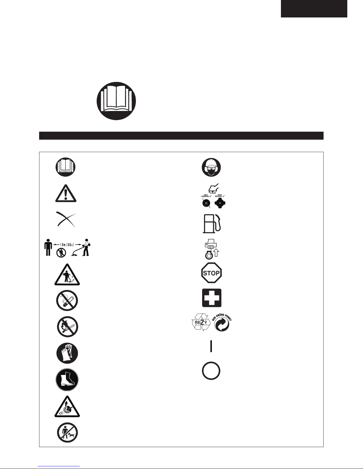
Take Particular care and attention!
Read instruction manual and follow
the warnings and safety precautions!
Forbidden!
No smoking!
No open ame!
Protective gloves must be worn!
Keep the area of operation clear of all
persons and pets!
Wear protective helmet, eye and ear
protection!
Engine-manual start
Top permissible tool speed
Emergency stop
ON/START
OFF/STOP
Flying object hazard!
Keep distance!
Kickback!
Recycling
Fuel (Gasoline)
First Aid
You will note the following symbols when reading the instructions manual.
SYMBOLS
Wear sturdy boots with nonslip soles.
Steeltoed safety boots are recommended!

4
General Instructions
– To ensure correct operation, user has to read this instruction manual to make
himself familiar with the handling of the Petrol Brushcutter. Users insufciently
informed will risk danger to themselves as well as others due to improper
handling.
– It is recommended only to lend the Petrol Brushcutter to people who have
proven to be experienced with Petrol Brushcutters.
Always hand over the instruction manual.
– First users should ask the dealer for basic instructions to familiarize oneself
with the handling of an engine powered cutter.
– Children and young persons aged under 18 years must not be allowed
to operate the Petrol Brushcutter. Persons over the age of 16 years may
however use the device for the purpose of being trained only whilst under
supervision of a qualied trainer.
– Use Petrol Brushcutters with the utmost care and attention.
– Operate the Petrol Brushcutter only if you are in good physical condition.
Perform all work calmly and carefully. The user has to accept liability for
others.
– Never use the Petrol Brushcutter after consumption of alcohol or drugs, or if
feeling tired or ill.
– National regulation can restrict the use of the machine.
Intended use of the machine
– The Petrol Brushcutter is only intended for cutter grass, weeds, Bushes,
undergrowth it should not be used for any other purpose such as Edging or
hedge cutting as this may cause injury.
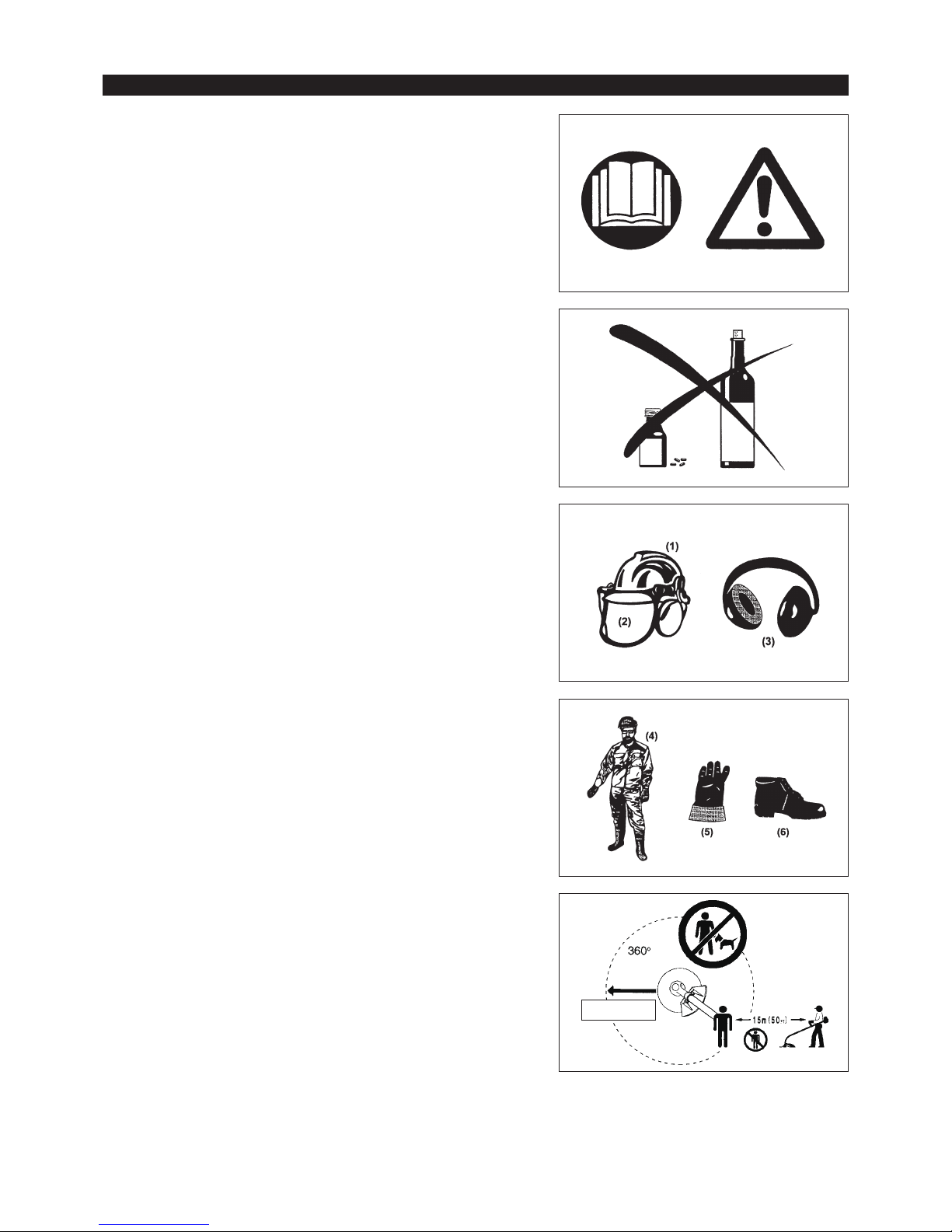
Personal protective equipment
– The clothing worn should be functional and appropriate, i.e. it should be tight-
tting but not cause hindrance. Do not wear either jewelry or clothing which
could become entangled with bushes or shrubs.
– In order to avoid either head-, eye-, hand-or foot injuries as well as to protect
your hearing the following protective equipment and protective clothing must
be used during operation of the Petrol Brushcutter.
– Always wear a helmet where there is a risk of falling objects. The protective
helmet (1) is to be checked at regular intervals for damage and is to be
replaced at the latest after 5 years. Use only approved protective helmets.
– The visor (2) of the helmet (or alternatively goggles) protects the face from
ying debris and stones. During operation of the Petrol Brushcutter always
wear goggles, or a visor to prevent eye injuries.
– Wear adequate noise protection equipment to avoid hearing impairment (ear
muffs (3), ear plugs etc.).
– The work overalls (4) protect against ying stones and debris.
We strongly recommend that the user wears work overalls.
– Special gloves (5) made of thick leather are part of the prescribed equipment
and must always be worn during operation of the Petrol Brushcutter.
– When using the Petrol Brushcutter, always wear sturdy shoes (6) with a non-
slip sole. This protects against injuries and ensures a good footing.
Starting up the Petrol Brushcutter
– Please make sure that there are no children or other people within a working
range of 15 meters (50 ft), also pay attention to any animals in the working
vicinity.
– Before use always check that the Petrol Brushcutter is safe for operation:
Check the security of the cutting tool, the control lever for easy action and
check for proper functioning of the control lever lock.
– Rotation of the cutting tool during idling speed is not allowed. Check with your
dealer for adjustment if in doubt. Check for clean and dry handles and test
the function of the start/stop switch.
15 Meters
Diagrammatic gure
SAFETY INSTRUCTIONS
5
Start the Petrol Brushcutter only in accordance with the instructions.
– Do not use any other methods for starting the engine!
– Use the Petrol Brushcutter and the tools only for such applications as
specied.
– Only start the Petrol Brushcutter engine, after the entire assembly is done.
Operation of the device is only permitted after all the appropriate accessories
are attached!
– Before starting make sure that the cutting tool has no contact with hard
objects such as branches, stones etc. as the cutting tool will revolve when
starting.
– The engine is to be switched off immediately in case of any engine problems.
– Should the cutting tool hit stones or other hard objects, immediately switch off
the engine and inspect the cutting tool.
– Inspect the cutting tool at short regular intervals for damage (detection of
hairline cracks by means of tapping-noise test).
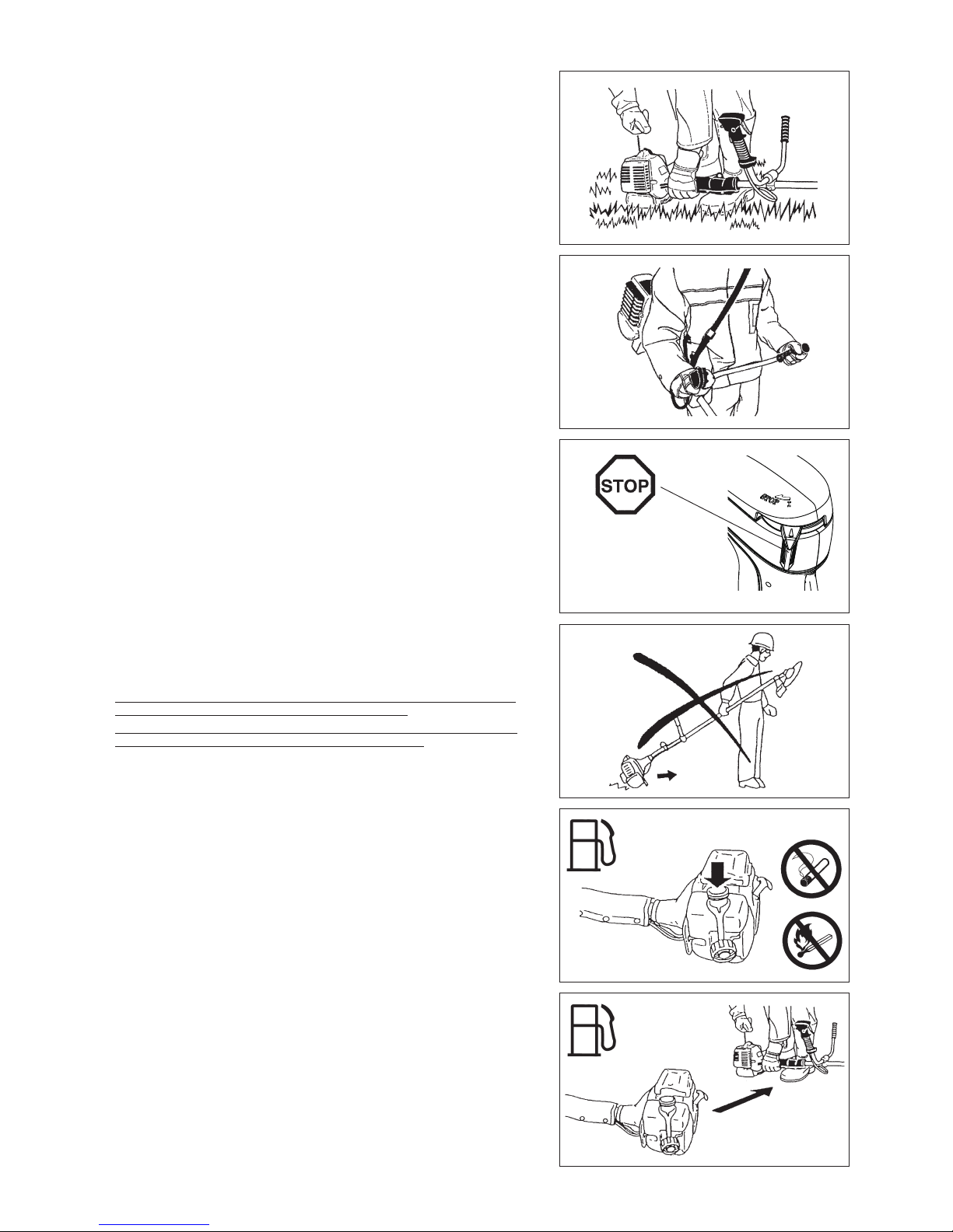
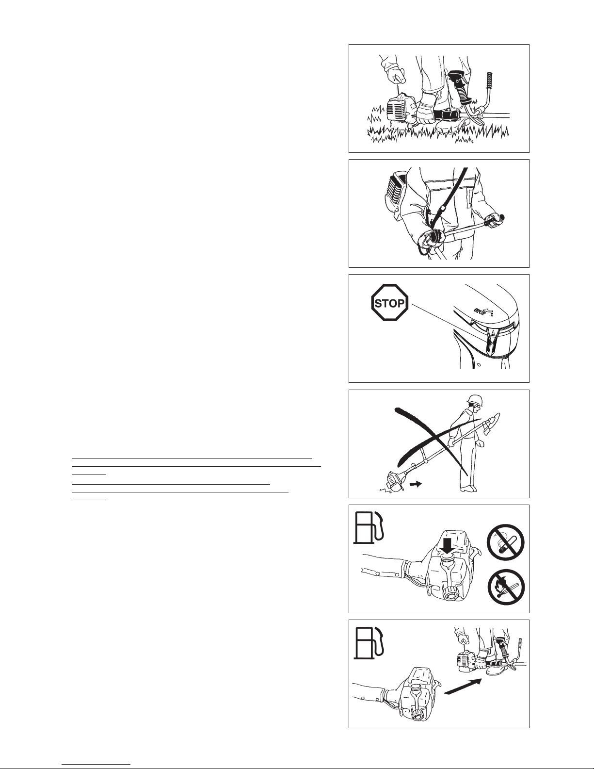
– Operate the Petrol Brushcutter only with the shoulder strap attached which is
to be suitably adjusted before putting the Petrol Brushcutter into operation. It
is essential to adjust the shoulder strap according to the user size to prevent
fatigue occurring during use. Never hold the cutter with one hand during use.
– During operation always hold the Petrol Brushcutter with both hands.
Always ensure a safe footing.
– Operate the Petrol Brushcutter in such a manner as to avoid inhalation of
the exhaust gases. Never run the engine in enclosed rooms (risk of gas
poisoning). Carbon monoxide is an odorless gas.
– Switch off the engine when resting and when leaving the Petrol Brushcutter
unattended, and place it in a safe location to prevent danger to others or
damage to the machine.
– Never put the hot Petrol Brushcutter onto dry grass or onto any combustible
materials.
– The cutting tool has to be equipped with it appropriate guard.
Never run the cutter without this guard!
– All protective installations and guards supplied with the machine must be
used during operation.
– Never operate the engine with faulty exhaust mufer.
– Shut off the engine during transport.
– During transport over long distances the tool protection included with the
equipment must always be used.
– Ensure safe position of the Petrol Brushcutter during car transportation to
avoid fuel leakage.
– When transporting the Petrol Brushcutter, ensure that the fuel tank is
completely empty.
–
When unloading the Petrol Brushcutter from the truck, never drop the Engine
to the ground or this may severely damage the fuel tank.
–
Except in case of emergency, never drop or cast the Petrol Brushcutter to the
ground or this may severely damage the Petrol Brushcutter.
– Remember to lift the entire equipment from the ground when moving the
equipment. Dragging the fuel tank is highly dangerous and will cause damage
and leakage of fuel, possibly causing re.
Refuelling
– Shut off the engine during refuelling, keep away from open ames and do not
smoke.
– Avoid skin contact with mineral oil products. Do not inhale fuel vapor. Always
wear protective gloves during refuelling. Change and clean protective clothing
at regular intervals.
– Take care not to spill either fuel or oil in order to prevent soil contamination
(environmental protection). Clean the Petrol Brushcutter immediately after
fuel has been spilt.
– Avoid any fuel contact with your clothing. Change your clothing instantly if
fuel has been spilt on it (to prevent clothing catching re).
– Inspect the fuel cap at regular intervals making sure that it can be securely
fastened and does not leak.
– Carefully tighten the fuel tank cap. Change location to start the engine (at
least 3 meters away from the place of refuelling).
– Never refuel in closed rooms. Fuel vapors accumulate at ground lever (risk of
explosions).
– Only transport and store fuel in approved containers. Make sure the fuel
stored is not accessible to children.
• Resting
• Transport
• Refuelling
• Maintenance
• Tool replacement
3 meters

6
Method of operation
– Only use the Petrol Brushcutter in good light and visibility. During the winter
season beware of slippery or wet areas, ice and snow (risk of slipping).
Always ensure a safe footing.
– Never cut above waist height.
– Never stand on a ladder and run the Petrol Brushcutter.
– Never climb up into trees to perform cutting operation with the Petrol
Brushcutter.
– Never work on unstable surfaces.
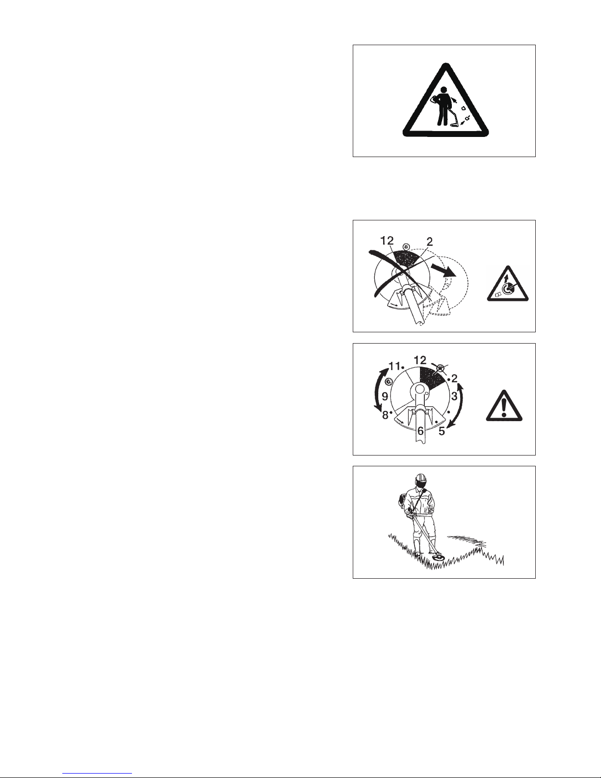
– Remove sand, stones, nails etc. found within the working range.
Foreign particles may damage the cutting tool and can cause dangerous
kick-backs.
– Before commencing cutting, the cutting tool must have reached full working
speed.
Caution:
Kickback
Diagrammatic
gure
Diagrammatic
gure
Kickback
– When operating the Petrol Brushcutter, uncontrolled kickback may occur.
– This is particularly the case when attempting to cut within a blade segment
between 12 and 2 o’clock.
– Never apply the Petrol Brushcutter within a segment between 12 and 2
o’clock.
– Never apply this segment of the Petrol Brushcutter blade to solids, such as
bushes and trees, etc., having a diameter in excess of 3 cm or the Petrol
Brushcutter will be deected at great force with the risk of injuries.
Kickback prevention
To avoid kickbacks, observe the following:
– Operation within a blade segment between 12 and 2 o’clock presents positive
hazards, especially when using metal cutting tools.
– Cutting operations within a blade segment between 11 and 12 o’clock, and
between 2 and 5 o’clock, must only be performed by trained and experienced
operators, and then only at their own risk.
Easy cutting with almost no kickback is possible within a blade segment
between 8 and 11 o’clock.
Maintenance instructions
– The condition of the cutter, in particular of the cutting tool of the protective
devices and also of the shoulder strap must be checked before commencing
work. Particular attention is to be paid to the cutting blades which must be
correctly sharpened.
– Turn off the engine and remove spark plug connector when replacing or
sharpening cutting tools, and also when cleaning the cutter or cutting tool.
Cutting Tools
Employ only the correct cutting tool for the job in hand.
EBH252U, EBH253U, EBH252L, EBH253L, BH252UG, EBH253UG,
EBH252LG, BH253LG with cutter blade, Nylon cutting head.
For cutting thick materials, such as weed, high grass, bushes, shrubs,
underwood, thicket etc. (max. 2 cm dia. thickness). Perform this cutting work by
swinging the Petrol Brushcutter evenly in half-circles from right to left (similar to
using a scythe).

7
Never straighten or weld damaged cutting tools.
– Operate the Petrol Brushcutter with as little noise and contamination as
possible. In particular check the correct setting of the carburetor.
– Clean the Petrol Brushcutter at regular intervals and check that all screws
and nuts are well tightened.
– Never service or store the Petrol Brushcutter in the vicinity of naked ames.
– Always store the Petrol Brushcutter in locked rooms and with an emptied fuel
tank.
Packaging
The MAKITA Petrol Brushcutter will be delivered in two protective cardboard
boxes to prevent transport damage. Cardboard is a basic raw material and
is therefore consequently reusable or suitable for recycling (waste paper
recycling).
Observe the relevant accident prevention instructions issued by the relevant trade associations and by the insurance companies.
Do not perform any modications on the Petrol Brushcutter as this will endanger your safety.
The performance of maintenance or repair work by the user is limited to those activities as described in the instruction manual. All other work is
to be done by an Authorized Service Agent. Use only genuine spare parts and accessories released and supplied by MAKITA.
Use of non-approved accessories and tools means increased risk of accidents.
MAKITA will not accept any liability for accidents or damage caused by the use of non-approved cutting tools and xing devices of cutting tools,
or accessories.
First Aid
In case of accident make sure that a rst-aid box is available in the vicinity of
the cutting operations. Immediately replace any item taken from the rst aid box.
When asking for help, please give the following
information:
– Place of accident
– What happened
– Number of injured persons
– Kind of injuries
– Your name

8
TECHNICAL DATA EBH252U, EBH252UG, EBH252L, EBH252LG
EBH252UG/EBH252LG: This model has adapted for use with Brazilian gasoline (E25).
Model
EBH252U
EBH252UG
EBH252L
EBH252LG
Bike handle Loop handle
Dimensions: length x width x height (without cutting blade) mm
1,770 x 620 x 490 1,770 x 330 x 275
Mass (without plastic guard and cutting blade) kg
5.7 5.3
Volume (fuel tank) L
0.5
Volume (oil tank) L 0.08
Engine displacement cm
3
24.5
Maximum engine performance kw 0.71 at 7,000 min
-1
Engine speed at recommended max. spindle speed min
-1
8,500
Maximum spindle speed (corresponding) min
-1
6,500
Maximum fuel consumption kg/h
0.33
Maximum specic fuel consumption g/kwh
408
Idling speed min
-1
3,000
Clutch engagement speed min
-1
3,750
Carburetor type
WALBRO WYL
Ignition system type Solid state ignition
Spark plug type
NGK CMR4A
Electrode gap mm 0.7 - 0.8
Fuel Automobile gasoline
Engine Oil
SAE 10W-30 oil of API Ciassication,
Class SF or higher (4-stroke engine for automobile)
Cutting tools (cutter blade dia.) mm 230
Gear ratio 14/19

9
TECHNICAL DATA EBH253U, EBH253UG, EBH253L, EBH253LG
EBH253UG/EBH253LG: This model has adapted for use with Brazilian gasoline (E25).
Model
EBH253U
EBH253UG
EBH253L
EBH253LG
Bike handle Loop handle
Dimensions: length x width x height (without cutting blade) mm
1,770 x 620 x 490 1,770 x 330 x 275
Mass (without plastic guard and cutting blade) kg
5.9 5.4
Volume (fuel tank) L
0.5
Volume (oil tank) L 0.08
Engine displacement cm
3
24.5
Maximum engine performance kw 0.71 at 7,000 min
-1
Engine speed at recommended max. spindle speed min
-1
8,500
Maximum spindle speed (corresponding) min
-1
6,500
Maximum fuel consumption kg/h
0.33
Maximum specic fuel consumption g/kwh
408
Idling speed min
-1
3,000
Clutch engagement speed min
-1
3,750
Carburetor type
WALBRO WYL
Ignition system type Solid state ignition
Spark plug type
NGK CMR4A
Electrode gap mm 0.7 - 0.8
Fuel Automobile gasoline
Engine Oil
SAE 10W-30 oil of API Ciassication,
Class SF or higher (4-stroke engine for automobile)
Cutting tools (cutter blade dia.) mm 230
Gear ratio 14/19
10
⑬
⑭
⑮
④
⑤
⑰
⑦
⑨
⑪
⑩
⑫
⑯
EBH252L/EBH252LG
EBH253L/EBH253LG
EBH252U/EBH252UG
EBH253U/EBH253UG
①
③
⑥
⑲
②
22
21
DESIGNATION OF PARTS
GB DESIGNATION OF PARTS
1 Fuel tank
2 Rewind starter
3 Air cleaner
4 I-O switch (on/off)
5 Spark plug
6 Exhaust mufer
7 Clutch case
8 Rear grip
9 Hanger
10 Handle
11 Control lever
12 Control cable
13 Shaft
14 Protector
15 Gear Case/Head case
16 Handle holder
17 Cutter blade
18 Nylon cutting head
19 Fuel ller cap
20 Starter knob
21 Exhaust pipe
22 Oil gauge
⑳
⑱
④
⑤
⑦
⑧
⑨
⑪
⑩
⑫
⑭
⑬
⑮
11
CAUTION: Before doing any work on the Petrol Brushcutter, always stop the
engine and pull the spark plug connector off the spark plug.
Always wear protective gloves!
CAUTION: Start the Petrol Brushcutter only after having assembled it
completely.
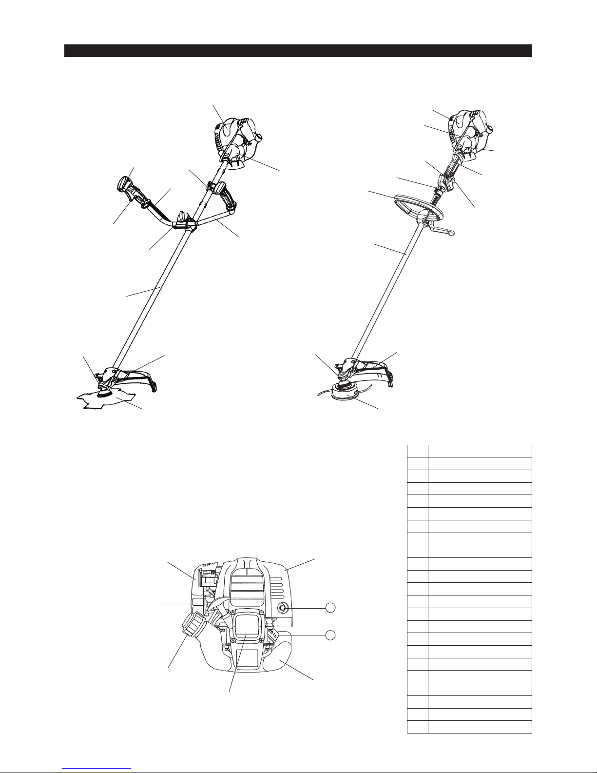
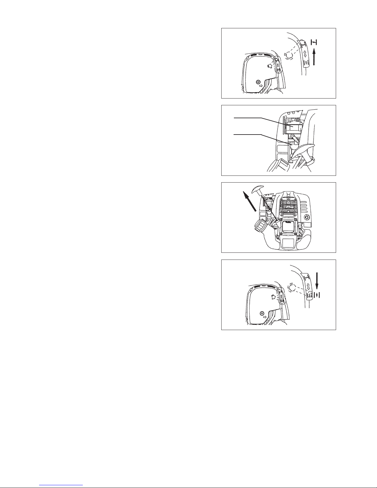
For machines with bike handle models
– Loosen knob (1).
– Place handle (4) between handle clamp (2) and handle holder (3).
– Adjust handle (4) to an angle that provides a comfortable working position
and then secure by rmly hand-tightening knob (1).
CAUTION: Do not forget to mount spring (5).
MOUNTING OF HANDLE
For machines with loop handle
– Fix a barrier to the left side of the machine together with the handle for
operator protection.
– Do not adjust position of the loop handle too close to the control grip. Keep
not less than 250 mm distance between the handle and the grip.
(a distance collar is provided for this purpose.)
(1)
(2)
(3)
(4)
(5)
Engine
Engine
12
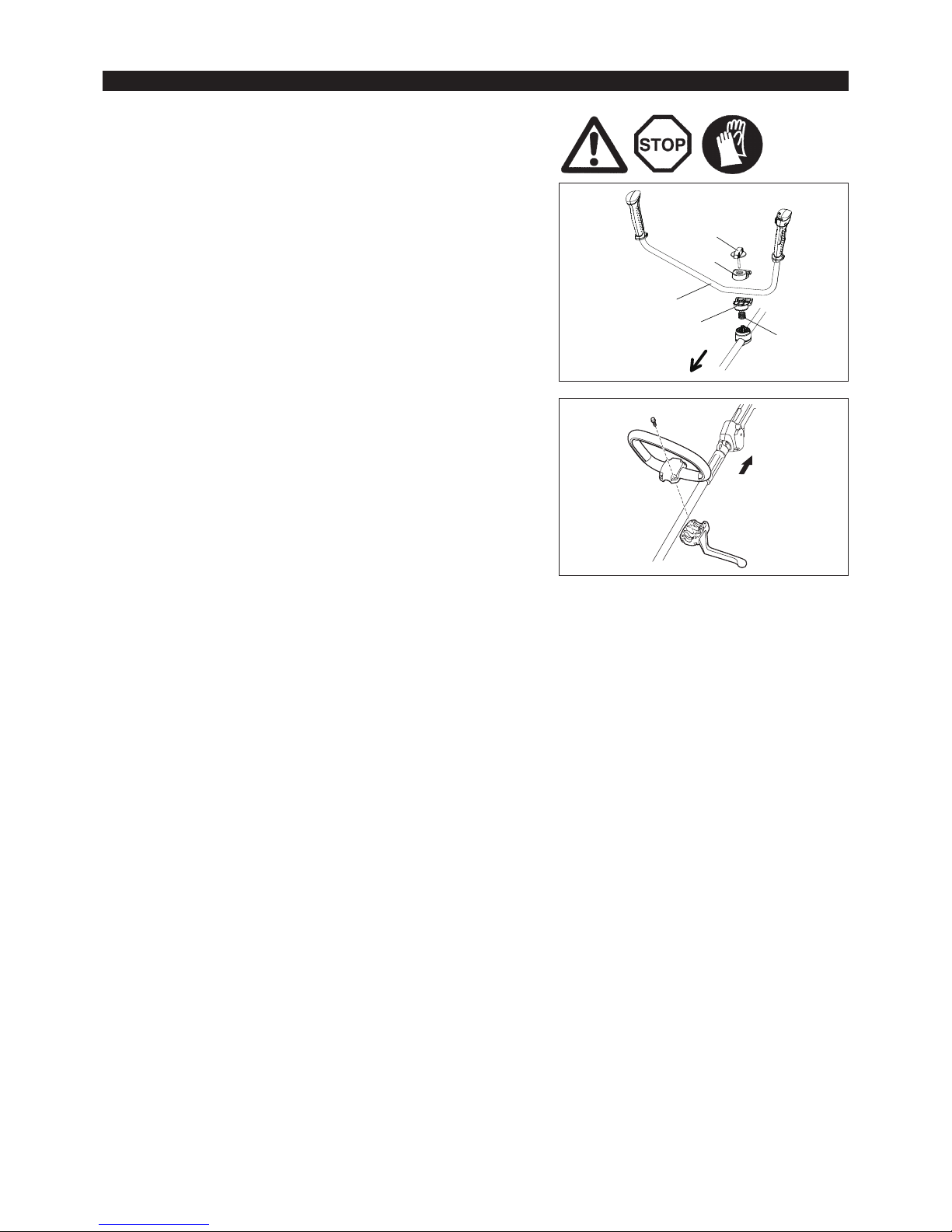
To meet the applicable safety provisions, only the tool/
protector combinations as indicated in the table must be used.
Be sure to use genuine MAKITA cutter blades or
nylon cutting head.
– The cutter blade must be well polished, free of cracks or
breakage. If the cutter blade hits against a stone during
operation, stop the engine and check the blade immediately.
– Polish or replace the cutter blade every three hours of operation.
– If the nylon cutting head hits against a stone during operation,
stop the engine and check the nylon cutting head immediately.
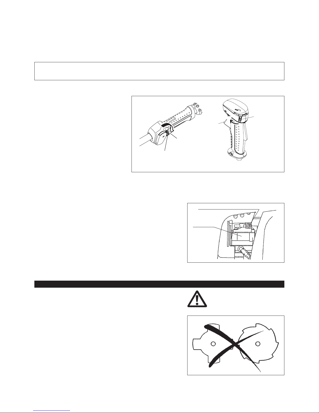
CAUTION: The appropriate protector must always be installed, for
your own safety and in order to comply with accidentprevention regulations.
Operation of the equipment without the guard being in
place is not permitted.
The outside diameter of the cutter blade must be
230 mm (9 - 1/16”). Never use any blades surpassing
230 mm (9 - 1/16”) in outside diameter.
Metal blade
Protector for metal blades
Nylon cutting head
Protector for
nylon cutting head
(3)
(2)
(1)
(3)
(4)
MOUNTING OF PROTECTOR
– In use of the metal blade, x the protector (3) to the clamp (2) with two bolts
M6 x 30 (1).
NOTE: Tighten the right and left bolts evenly so that the gap between the clamp
(2) and the protector (3) will be constant.
Otherwise, the protector sometimes may not function as specied.
– In cases where the nylon cord cutter is to be used, be sure to mount the
nylon cord cutter protector (4) onto the metal blade protector (3).
– Mount the nylon cord cutter protector (4) by sliding it into place from the ank
of the metal blade protector (3) as shown.
– Remove tape adhered to cutter, which cuts nylon cord, on nylon cord cutter
protector (4).
CAUTION: Be sure to push in nylon cord cutter protector (4) until it is fully
inserted.
Take care not to injure yourself on the cutter for cutting the nylon
cord.
– To remove the nylon cord cutter protector (4), apply a hex wrench into the
notch on the metal blade protector (3), push it in and meanwhile slide the
nylon cord cutter protector (4).
Hex wrench
13
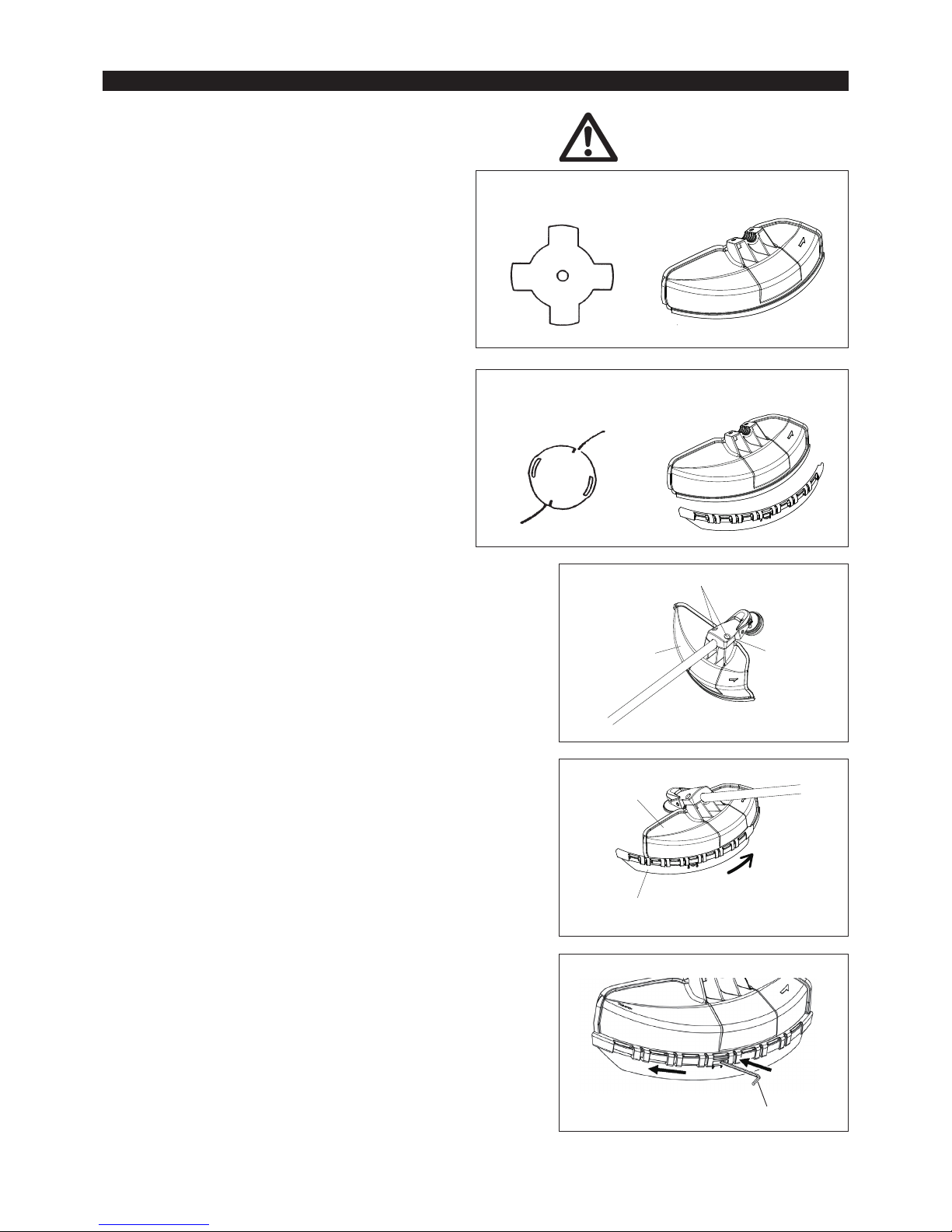
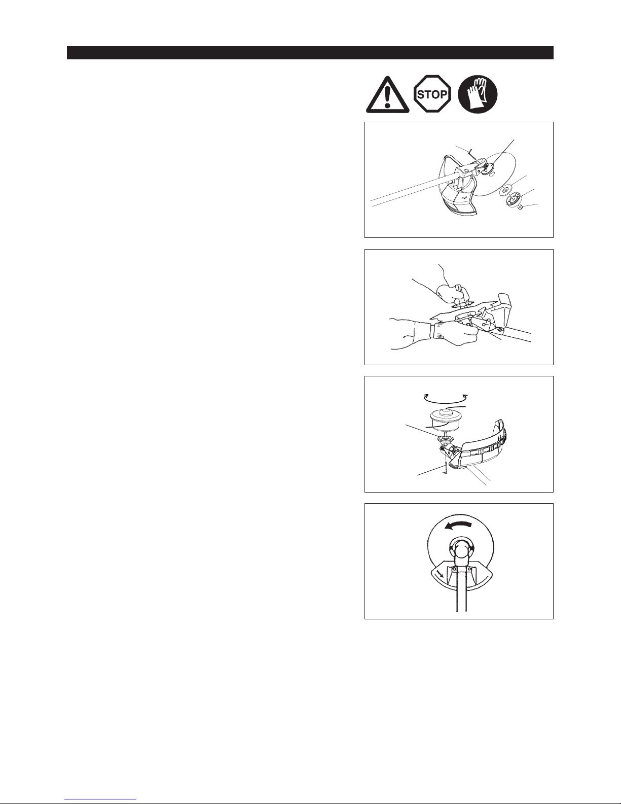
Turn the machine upside down, and you can replace the cutter blade or nylon
cutting head easily.
– Insert the hex wrench through the hole in the gear case and rotate the
receiver washer (4) until it is locked with the hex wrench.
– Loosen the nut (1) (left-hand thread) with the socket wrench and remove the
nut (1), cup (2), and clamp washer (3).
Rotation
Hex wrench
MOUNTING OF CUTTER BLADE OR NYLON CUTTING HEAD
Mounting of cutterblade with the hex wrench still in place
– Mount the cutter blade onto the shaft so that the guide of the receiver washer
(4) ts in the arbor hole in the cutter blade. Install the clamp washer (3), cup
(2), and secure the cutter blade with the nut (1).
[Tightening torque: 13 - 23 N-m]
NOTE: Always wear gloves when handling the cutter blade.
NOTE: The cutter blade-fastening nut (with spring washer) is a consumable
part. If there appears any wear or deformation on the spring washer,
replace the nut.
Mounting of nylon cutting head
– The clamp washer (3), cup (2), and nut (1) are not necessary for mounting
the nylon cutting head. The nylon cutting head should go on top of the
receiver washer (4).
– Insert the hex wrench through the hole in the gear case and rotate the
receiver washer (4) until it is locked with the hex wrench.
– Then screw the nylon cutting head onto the shaft by turning it counter-
clockwise.
– Remove the hex wrench.
– Make sure that the blade is the left way up.
(3)
(2)
(1)
Hex wrench
Loosen
Tighten
Hex wrench
(4)
(4)
14
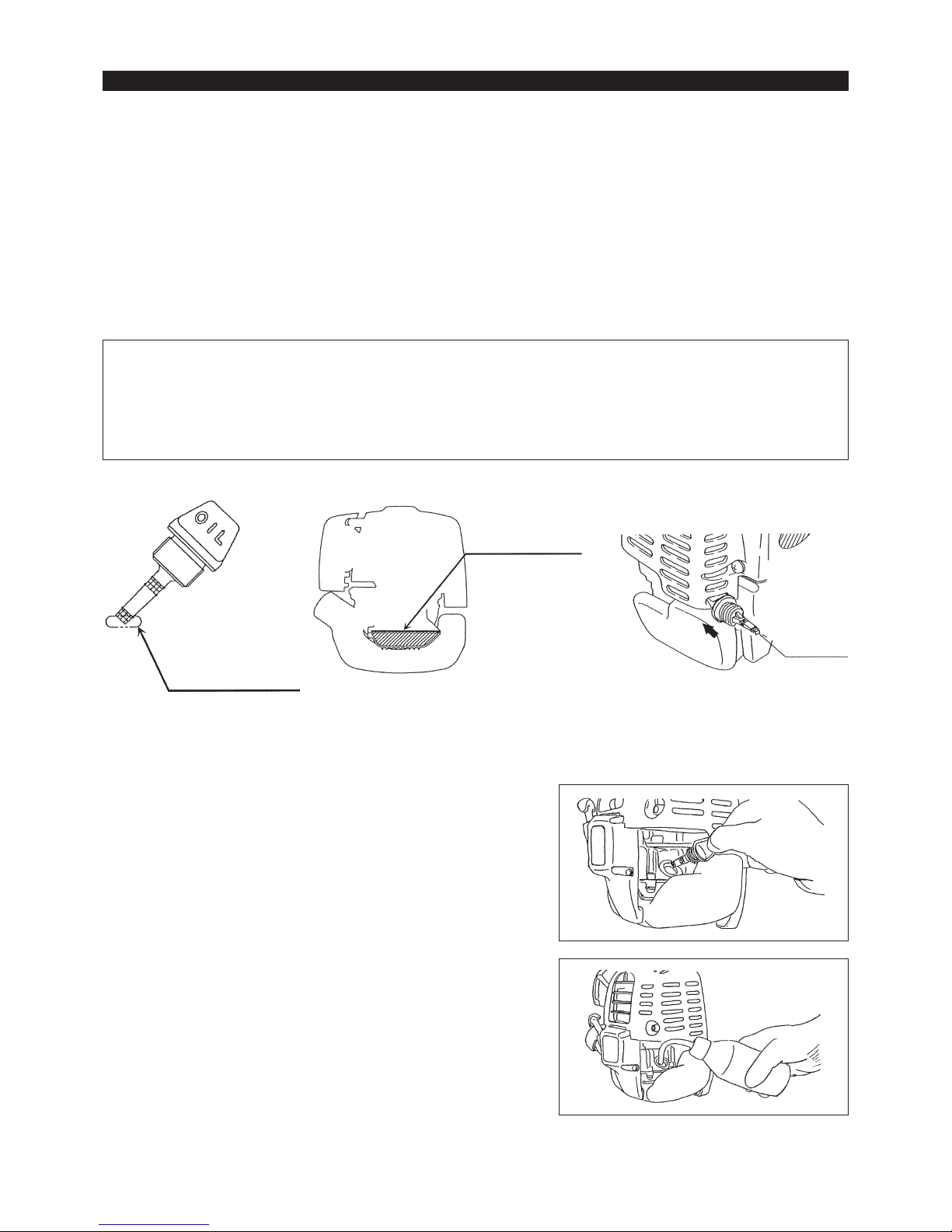
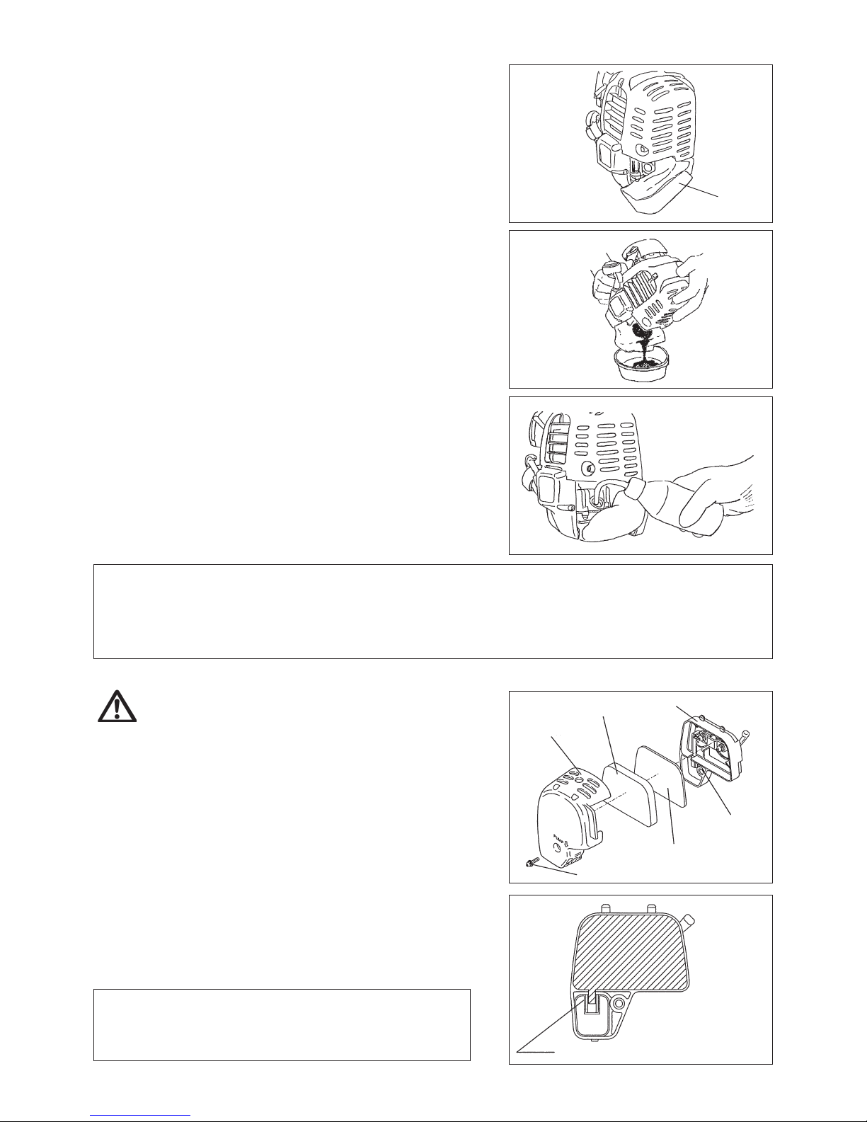
Inspection and rell of engine oil
– Perform the following procedure, with the engine cooled down.
– While keeping the engine level, remove the oil gauge, and conrm that the oil is lled within the upper and lower limit marks.
When the oil is in short in such a way that the oil gauge touches the oil only by its tip, in particular with the oil gauge remaining inserted in the
crankcase without screwing-in (Fig. 1), rell new oil near the port (Fig. 2).
– For reference, the oil rell time is about 10h (10 times or 10 tanks of oil rell).
If the oil changes in color or mixes with dirt, replace it with new one. (For the interval and method of replacement, refer to P 20)
Recommended oil: SAE 10W-30 oil of API Classication, Class SF or higher (4-stroke engine for automobile)
Oil volume: Approx. 0.08L
Note: If the engine is not kept upright, oil may go into around the engine, and may be relled excessively.
If the oil is lled above the limit, the oil may be contaminated or may catch re with white smoke.
Point 1 in Replacement of oil: “Oil gauge”
– Remove dust or dirt near the oil rell port, and detach the oil gauge.
– Keep the detached oil gauge free of sand or dust. Otherwise, any sand or dust adhering to the oil gauge may cause irregular oil
circulation or wear on the engine parts, which will result in troubles.
– As an example to keep the oil gauge clean, it is recommended to insert the oil gauge on its knob side into the engine cover, as shown
in Fig. 3.
Oil gauge
If oil adheres around
this tip, rell new oil.
Fig. 1
Upper limit
(Edge of oil rell port)
Fig. 2
Fig. 3
BEFORE START OF OPERATION
(1) Keep the engine level, and detach the oil gauge.
(2) Fill oil up to the edge of the oil rell port. (Refer to Fig. 2 of the preceding
page).
Feed oil with the lubricant rell container.
(3) Securely tighten the oil gauge. Insufcient tightening may cause oil leakage.
15
REFUELING
Handling of fuel
It is necessary to handle fuel with utmost care. Fuel may contain substances similar to solvents. Refueling must be performed in a sufciently
ventilated room or in the open air. Never inhale fuel vapor, and keep fuel away from you. If you touch fuel repeatedly or for a long time, the
skin becomes dry, which may cause skin disease or allergy. If fuel enters into the eye, clean the eye with fresh water. If your eye remains still
irritated, consult your doctor.
Storage period of fuel
Fuel should be used up within a period of 4 weeks, even if it is kept in a special container in a well-ventilated shade.
If a special container is not used or if the container is not covered, fuel may deteriorate in one day.
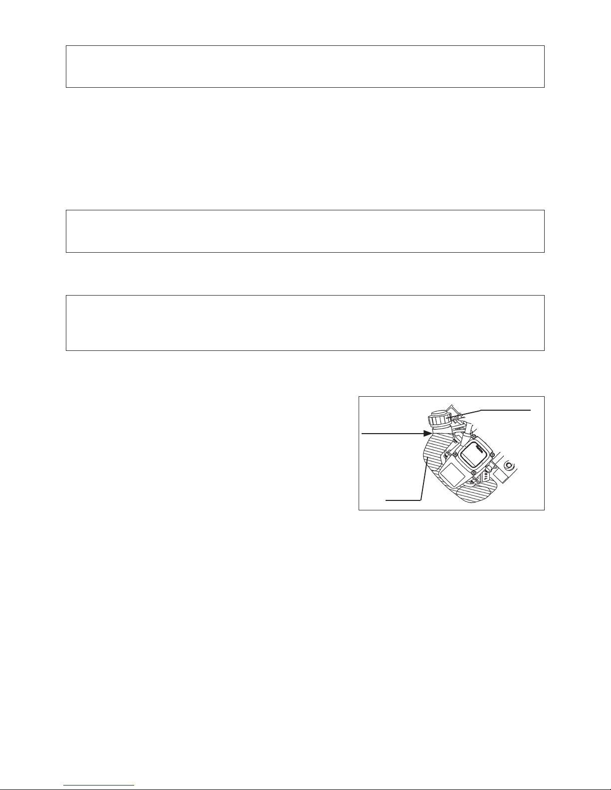
Refueling
WARNING: INFLAMMABLES STRICTLY PROHIBITED
Gasoline used: Automobile gasoline (unleaded gasoline)
– Loosen the tank cap a little so that there will be no difference in atmospheric
pressure.
– Detach the tank cap, and refuel, discharging air by tilting the fuel tank so
that the refuel port will be oriented upward. (Never rell fuel full to the oil rell
port.)
– Wipe well the periphery of the tank cap to prevent foreign matter from
entering into the fuel tank.
– After refueling, securely tighten the tank cap.
● If there is any aw or damage on the tank cap, replace it.
● The tank cap is consumable, and therefore should be renewed every two to
three years.
Fuel tank cap
Fuel upper limit
Fuel tank
Fuel
The engine is a four-stroke engine. Be sure to use an automobile gasoline (regular gasoline or premium gasoline).
Point 2 in Replacement of oil: “If oil spills out”
– If oil spills out between the fuel tank and engine main unit, the oil is sucked into through the cooling air intake port, which will
contaminate the engine. Be sure to wipe out spilt oil before start of operation.
STORAGE OF MACHINE AND REFILL TANK
– Keep the machine and tank at a cool place free from direct sunshine.
– Never keep the fuel in the cabin or trunk.
Points for fuel
– Never use a gasoline mixture which contains engine oil. Otherwise, it will cause excessive carbon accumulation or mechanical troubles.
– Use of deteriorated oil will cause irregular startup.
– EBH252UG/EBH253UG/EBH252LG/EBH253LG: This model has adapted for use with Brazilian gasoline (E25).
16
Observe the applicable accident prevention regulations!
STARTING
Move at least 3 m away from the place of refuelling. Place the Petrol Brushcutter on a clean piece of ground taking care that the cutting tool
does not come into contact with the ground or any other objects.
A: Cold start
1) Set this machine on a at space.
CORRECT HANDLING OF MACHINE
POINTS IN OPERATION AND HOW TO STOP
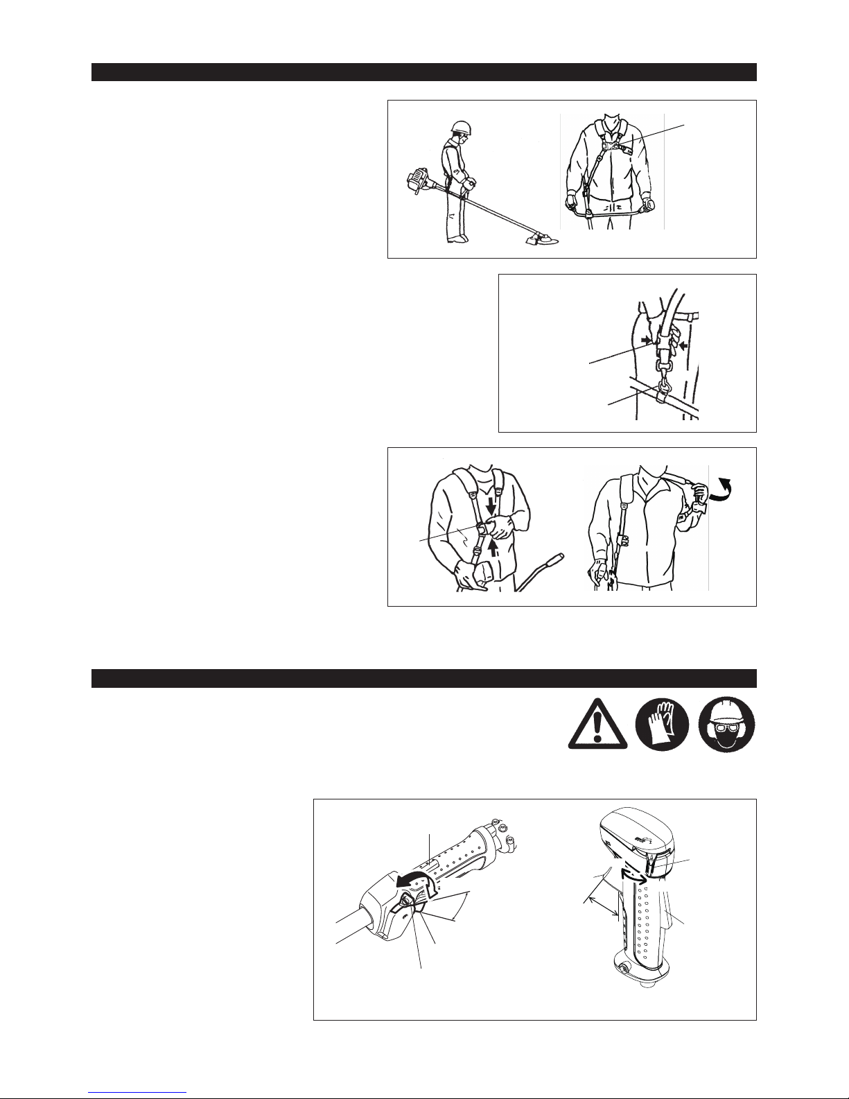
Detachment
For EBH252L, EBH252LG, EBH253L, EBH253LG
– In an emergency, push the notches (1) at both sides, and you can detach the
machine from you.
Be extremely careful to maintain control of the machine at this time. Do not
allow the machine to be deected toward you or anyone in the work vicinity.
WARNING: Failure to maintain complete control of the machine at all could
result in serious bodily injury or DEATH.
EBH252L/EBH252LG
EBH253L/EBH253LG
EBH252U/EBH252UG
EBH253U/EBH253UG
STOP
OPERATION
Lock-off lever
High speed
Low speed
Throttle lever
(1)
Attachment of shoulder strap
– Adjust the strap length so that the cutter blade will be
kept parallel with the ground.
For EBH252U, EBH252UG, EBH253U, EBH253UG
NOTE: Be careful not to trap clothing, etc., in the buckle.
OPERATION
Lock-off lever
High speed
Low speed
Throttle lever
Hanger
For EBH252U, EBH252UG, EBH253U, EBH253UG
– In an emergency, push the notches (2) at both sides, and
you can detach the machine from you.
Be extremely careful to maintain control of the machine
at this time. Do not allow the machine to be deected
toward you or anyone in the work vicinity.
WARNING: Failure to maintain complete control of the
machine at all could result in serious bodily
injury or DEATH.
STOP
(1)
(1)
Buckle
(2)
EBH252U/EBH252UG
EBH253U/EBH253UG
17
2) Set the I-O switch (1) to OPERATION.
3) Choke lever
Close the choke lever.
Choke opening:
– Full closing in cold or when the engine is cold.
– Full or half opening in restart just after stop of operation.
Note: – If the starter handle is pulled repeatedly when the choke lever remains at “CLOSE” position, the engine will not start easily due to
excessive fuel intake.
– In case of excessive fuel intake, remove the spark plug and pull the starter handle slowly to remove excess fuel. Also, dry the electrode
section of the spark plug.
Caution during operation:
If the throttle lever is opened fully in a no-load operation, the engine rotation is increased to 10,000 min-1 or more. Never operate the engine at a
higher speed than required and at an approximate speed of 6,000 - 8,500 min-1.
OPEN
CLOSE
Carburetor
Primer Pump
4) Primer pump
Continue to push the primer pump until fuel enters into the primer pump. (In
general, fuel enters into the primer pump by 7 to 10 pushes.)
If the primer pump is pushed excessively, an excess of gasoline returns to
the fuel tank.
5) Recoil starter
Pull the start knob gently until it is hard to pull (compression point). Then,
return the start knob, and pull it strongly.
Never pull the rope to the full. Once the start knob is pulled, never release
your hand immediately. Hold the start knob until it returns to its original
point.
6) Choke lever
When the engine starts, open the choke lever.
– Open the choke lever progressively while checking the engine operation.
Be sure to open the choke lever to the full in the end.
– In cold or when the engine is cooled down, never open the choke lever
suddenly. Otherwise, the engine may stop.
7) Warm-up operation
Continue warm-up operation for 2 to 3 minutes.
18
B: Startup after warm-up operation
1) Push the primer pump repeatedly.
2) Keep the throttle lever at the idling position.
3) Pull the recoil starter strongly.
4) If it is difcult to start the engine, open the throttle by about 1/3.
Pay attention to the cutter blade which may rotate.
STOPPING
1) Release the throttle lever (2) fully, and when the
engine rpm has lowered, set the I-O switch to
STOP the engine will now stop.
2) Be aware that the cutting head may not stop
immediately and allow it to slow down fully.
ADJUSTMENT OF LOW-SPEED ROTATION (IDLING)
When it is necessary to adjust the low-speed rotation (idling), perform it by the carburetor adjusting screw.
CHECKUP OF LOW-SPEED ROTATION
– Set the low-speed rotation to 3,000 min-1.
If it is necessary to change the rotation speed, regulate the adjusting screw
(illustrated on the right), with Phillips screwdriver.
– Turn the adjusting screw to the right, and the engine rotation will increase.
Turn the adjusting screw to the left, and the engine rotation will drop.
– The carburetor is generally adjusted before shipment. If it is necessary to
readjust it, please contact Authorized Service Agent.
Adjusting screw
Carburetor
CAUTION: The cutting tools mentioned below must only be resharpened by an
authorized facility. Manual resharpening will result in imbalances of
the cutting tool causing vibrations and damage to the equipment.
– cutter blade
An expert resharpening and balancing service is provided by Authorized
Service Agents.
NOTE: To increase the service life of the cutter blade it may be turned over
once, until both cutting edges have become blunt.
Attention in Operation
When the engine is operated upside down, white smoke may come out from the mufer.
RESHARPENING THE CUTTING TOOL
STOP
(1)
(2)
EBH252L/EBH252LG
EBH253L/EBH253LG
EBH252U/EBH252UG
EBH253U/EBH253UG
STOP
(1)
(2)

19
NYLON CUTTING HEAD
The nylon cutting head is a dual string trimmer head capable of both automatic
and bump & feed mechanisms.
The nylon cutting head will automatically feed out the proper length of nylon
cord by the changes in centrifugal force caused by increasing or decreasing
rpms. However, to cut soft grass more efciently, bump the nylon cutting head
against the ground to feed out extra cord as indicated under operation section.
Operation
– Increase the nylon cutting head speed to approx. 6,000 min-1.
Low speed (under 4,800 min-1) is not suitable, the nylon cord will not feed out
properly at low speed.
– The most effective cutting area is shown by the shaded area.
If the nylon cord does not feed out automatically proceed as follows:
1. Release the throttle lever to run the engine idle and then squeeze the
throttle lever fully. Repeat this procedure until the nylon cord feeds out to
the proper length.
2. If the nylon cord is too short to feed out automatically with the above
procedure, bump the knob of the nylon cutting head against the ground to
feed out the nylon cord.
3. If the nylon cord does not feed out with procedure 2, rewind/replace the
nylon cord by following the procedures described under “Replacing the
nylon cord”.
Most effective cutting area
Idle speed
Full speed
Knob
Cover
Latches
Press
Press
80 mm (3 - 1/8”)
Spool
For left hand rotation
Spool
100 mm (3 - 15/16”)
Notches
Eyelets
Replacing the nylon cord
– First, stop the engine.
– Press on the housing latches inward to lift off the cover, then remove the
spool.
– Hook the center of new nylon cord into the notch in the center of the spool,
with one end of the cord extending about 80 mm (3 - 1/8”) more than the
other.
Then wind both ends rmly around the spool in the direction of the head
rotation (left-hand direction indicated by LH and right-hand direction by RH on
the side of the spool).
– Wind all but about 100 mm (3 - 15/16”) of the cords, leaving the ends
temporarily hooked through a notch on the side of the spool.
– Mount the spool in the housing so that the grooves and protrusions on the
spool match up with those in the housing. Keep the side with letters on
the spool visible on the top. Now, unhook the ends of the cord from their
temporary position and feed the cords through the eyelets to come out of the
housing.

20
REPLACEMENT OF ENGINE OIL
Deteriorated engine oil will shorten the life of the sliding and rotating parts to a great extent. Be sure to check the period and quantity of
replacement.
ATTENTION: In general, the engine main unit and engine oil still remain hot just after the engine is stopped. In replacement of oil,
conrm that the engine main unit and engine oil are sufciently cooled down. Otherwise, there may remain a risk of
scald.
Note: If the oil lled above the limit, it may be contaminated or may catch re with white smoke.
Interval of replacement: Initially, every 20 operating hours, and subsequently every 50 operating hours
Recommended oil: SAE10W-30 oil of API Classication SF Class or higher (4-stroke engine oil for automobile)
– Align the protrusion on the underside of the cover with the slots of the
eyelets.
Then push cover rmly onto the housing to secure it.
Cover
Protrusion
Slot of eyelet
In replacement, perform the following procedure.
1) Conrm that the tank cap is tightened securely.
2) Detach the oil gauge.
Keep the oil gauge free from dust or dirt.
Fuel tank cap
Oil gauge
CAUTION: Before doing any work on the Petrol Brushcutter, always stop the engine and pull the plug cap off the spark plug (see “checking the
spark plug”).
Always wear protective gloves!
To ensure a long service life and to avoid any damage to the equipment, the following servicing operations should be performed at regular
intervals.
Daily checkup and maintenance
– Before operation, check the machine for loose screws or missing parts. Pay particular attention to the tightness of the cutter blade or nylon
cutting head.
– Before operation, always check for clogging of the cooling air passage and the cylinder ns.
Clean them if necessary.
– Perform the following work daily after use:
• Clean the Petrol Brushcutter externally and inspect for damage.
• Clean the air lter. When working under extremely dusty conditions, clean the lter the severall times a day.
• Check the blade or the nylon cutting head for damage and make sure it is rmly mounted.
• Check that there is sufcient difference between idling and engagement speed to ensure that the cutting tool is at a standstill while the
engine is idling (if necessary reduce idling speed).
If under idling conditions the tool should still continue to run, consult your nearest Authorized Service Agent.
– Check the functioning of the I-O switch, the lock-off lever, the control lever, and the look button.
SERVICING INSTRUCTIONS
21
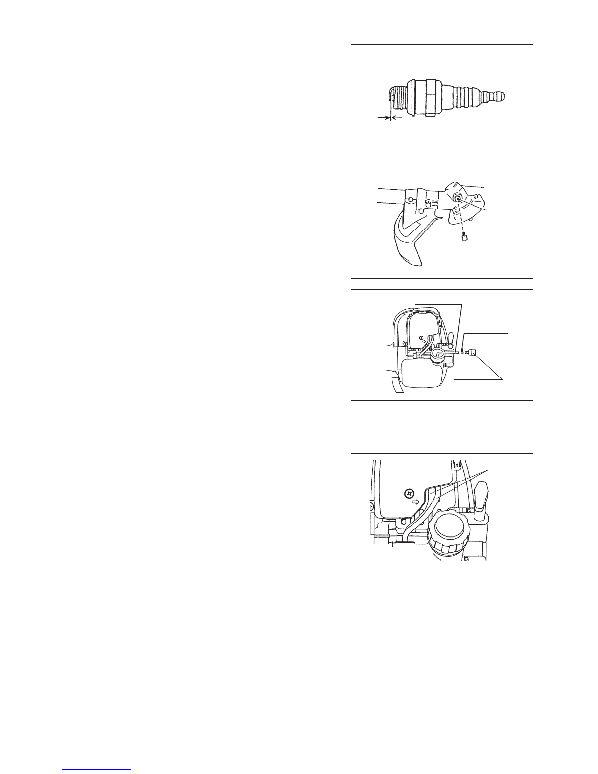
CLEANING OF AIR CLEANER
DANGER: INFLAMMABLES STRICTLY PROHIBITED
Interval of Cleaning and Inspection: Daily (every 10 operating hours)
– Turn the choke lever to the full close side, and keep the carburetor off from
dust or dirt.
– Remove the air cleaner cover-xing bolts.
– Pull the cover lower side and detach the air cleaner cover.
– If oil adheres to the element (sponge), squeeze it rmly.
– For heavy contamination:
1) Remove the element (sponge), immerse it in warm water or in waterdiluted neutral detergent, and dry it completely.
2) Clean the element (felt) with gasoline, and dry it completely.
– Before attaching the element, be sure to dry it completely. Insufcient drying
of the element may lead to difcult startup.
– Wipe out with waste cloth, oil adhering around the air cleaner cover and plate
breather.
– Immediately after cleaning is nished, attach the cleaner cover and tighten it
with xing bolts. (In remounting, rst place the upper claw, and then the lower
claw.)
Pick this part and remove the element (felt).
Plate
Element (sponge)
Air cleaner cover
Fixing bolt
Element (felt)
Breather Part
Waste or paper
3) Place waste or paper near the oil rell port.
POINTS ON OIL
– Never discard replaced engine oil in garbage, earth or sewage ditch. Disposal of oil is regulated by law. In disposal, always follow the
relevant laws and regulations. For any points remaining unknown, contact Authorized Service Agent.
– Oil will deteriorate even when it is kept unused. Perform inspection and replacement at regular intervals (replace with new oil every
6 months).
Points in Handling Air Cleaner Element
– Clean the element several times a day, if excessive dust adheres to it.
– If operation continues with the element remaining not cleared of oil, oil
in the air cleaner may fall outside, resulting in oil contamination.
4) Detach the oil gauge, and drain oil, tilting the main unit toward the oil rell
port.
Drain oil in a container for orderly disposal.
5) Keep the engine level, and feed new oil up to the edge of the oil rell port.
In rell, use a lubricant rell container.
6) After rell, securely tighten the oil gauge. Insufcient tightening of the oil
gauge will lead to oil leakage.
22
CLEANING OF FUEL FILTER
WARNING: INFLAMMABLES STRICTLY PROHIBITED
Interval of Cleaning and Inspection: Monthly (every 50 operating hours)
Suction head in the fuel tank
– The fuel lter (1) of the suction head is used to lter the fuel required by the
carburetor.
– A periodical visual inspection of the fuel lter is to be conducted. For that
purpose open the tank cap, use a wire hook and pull out the suction head
through the tank opening. Filters found to have hardened, been polluted or
clogged up are to be replaced.
– Insufcient fuel supply can result in the admissible maximum speed being
exceeded. It is therefore important to replace the fuel lter at least quarterly to
ensure satisfactory fuel supply to the carburetor.
REPLACEMENT OF FUEL PIPE
CAUTION: INFLAMMABLES STRICTLY PROHIBITED
Interval of Cleaning and Inspection: Daily (every 10 operating hours)
Replacement: Annually (every 200 operating hours)
Replace the fuel pipe every year, regardless of operating frequency. Fuel
leakage may lead to re.
If any leakage is detected during inspection, replace the oil pipe immediately.
INSPECTION OF BOLTS, NUTS AND SCREWS
– Retighten loose bolts, nuts, etc.
– Check for fuel and oil leakage.
– Replace damaged parts with new ones for safety operation.
CLEANING OF PARTS
– Keep the engine always clean.
– Keep the cylinder ns free of dust or dirt. Dust or dirt adhering to the ns will
cause piston seizure.
Fuel pipe
House clamp
Fuel pipe
0.7 mm - 0.8 mm
(0.028” - 0.032”)
CHECKING THE SPARK PLUG
– Only use the supplied universal wrench to remove or to install the spark plug.
– The gap between the two electrodes of the spark plug should be 0.7 - 0.8 mm
(0.028” - 0.032”). If the gap is too wide or too narrow, adjust it. If the spark
plug is clogged or contaminated, clean it thoroughly or replace it.
CAUTION: Never touch the spark plug connector while the engine is running
(danger of high voltage electric shock).
REPLACEMENT OF GASKETS AND PACKINGS
In reassembling after the engine is dismounted, be sure to replace the gaskets and packings with new ones.
Any maintenance of adjustment work that is not included and described in this manual is only to be performed by Authorized Service Agents.
Gear case
Grease hole
SUPPLY OF GREASE TO GEAR CASE
– Supply grease (Shell Alvania 2 or equivalent) to the gear case through the
grease hole every 30 hours. (Genuine MAKITA grease may be purchased
from your MAKITA dealer.)
Fuel
lter (1)

23
WARNING: When draining the fuel, be sure to stop the engine and conrm that the engine cools
down.
Just after stopping the engine, it may still hot with possibility of burns, inammability and re.
ATTENTION: When the machine is kept out of operation for a long time, drain up all fuel from the
fuel tank and carburetor, and keep it at a dry and clean place.
Fault location
– Drain up fuel from the fuel tank and carburetor according to the following
procedure:
1) Remove the fuel tank cap, and drain fuel completely.
If there is any foreign matter remaining in the fuel tank, remove it
completely.
2) Pull out the fuel lter from the rell port using a wire.
3) Push the primer pump until fuel is drained from there, and drain fuel
coming into the fuel tank.
4) Reset the lter to the fuel tank, and securely tighten the fuel tank cap.
5) Then, continue to operate the engine until it stops.
– Remove the spark plug, and drip several drops of engine oil through the
spark plug hole.
– Gently pull the starter handle so that engine oil will spread over the engine,
and attach the spark plug.
– Attach the cover to the cutter blade.
– During storage, keep the rod horizontal or keep the machine upright with the
blade edge oriented upward. (In this case, pay full attention to prevent the
machine from falling.)
Never store the machine with the cutter blade edge oriented downward.
Lubricating oil may spill out.
– Keep the drained fuel in a special container in a well-ventilated shade.
Drain fuel
Humidity
STORAGE
Attention after long-time storage
– Before startup after long-time shutdown, be sure to replace oil (refer to P 20). Oil will deteriorate while the machine is kept out of
operation.
Fault System Observation Cause
Engine not starting or with
difculty
Ignition system Ignition spark O.K. Fault in fuel supply or compression system, mechanical
defect
No ignition spark STOP-switch operated, wiring fault or short circuit, spark
plug or connector defective, ignition module faulty
Fuel supply Fuel tank lled Incorrect choke position, carburetor defective, fuel supply
line bent or blocked, fuel dirty
Compression No compression when
pulled over
Cylinder bottom gasket defective, crankshaft seals
damaged, cylinder or piston rings defective or improper
sealing of spark plug
Mechanical fault Starter not engaging Broken starter spring, broken parts inside of the engine
Warm start problems Tank lled ignition spark
existing
Carburetor contaminated, have it cleaned
Engine starts but dies Fuel supply Tank lled Incorrect idling adjustment, carburetor contaminated
Fuel tank vent defective, fuel supply line interrupted,
cable or STOP-switch faulty
Insufcient performance Several systems may
simultaneously be
affected
Engine idling poor Air lter contaminated, carburetor contaminated, mufer
clogged, exhaust duct in the cylinder clogged

24
*1 Perform initial replacement after 20h operation.
*2 For the 200 operating hour inspection, request Authorized Service Agent or a machine shop.
*3 After emptying the fuel tank, continue to run the engine and drain fuel in the carburetor.
Operating time
Item
Before
operation
After
lubrication
Daily
(10h)
30h 50h 200h
Shutdown/
rest
Corres-
ponding P
Engine oil
Inspect/clean 14
Replace *
1
20
Tightening parts
(bolt, nut)
Inspect 22
Fuel tank
Clean/inspect —
Drain fuel *
3
23
Throttle lever Check function —
Stop switch Check function 18
Cutting blade Inspect 12
Low-speed rotation Inspect/adjust 18
Air cleaner Clean 21
Ignition plug Inspect 22
Cooling air duct Clean/inspect 22
Fuel pipe
Inspect 22
Replace *
2
—
Gear-case grease Rell 22
Fuel lter Clean/replace 22
Clearance between air intake
valve and air discharge valve
Adjust *
2
—
Engine overhaul *
2
—
Carburetor Drain fuel *
3
23

25
TROUBLESHOOTING
Before making a request for repairs, check a trouble for yourself. If any abnormality is found, control your machine according to the description
of this manual. Never tamper or dismount any part contrary to the description. For repairs, contact Authorized Service Agent or local dealership.
When the engine does not start after warm-up operation:
If there is no abnormality found for the check items, open the throttle by about 1/3 and start the engine.
State of abnormality Probable cause (malfunction) Remedy
Engine does not start
Failure to operate primer pump Push 7 to 10 times
Low pulling speed of starter rope Pull strongly
Lack of fuel Feed fuel
Clogged fuel lter Clean
Broken fuel tube Straighten fuel tube
Deteriorated fuel Deteriorated fuel makes starting more difcult.
Replace with new one. (Recommended
replacement: 1 month)
Excessive suction of fuel Set throttle lever from medium speed to high
speed, and pull starter handle until engine
starts. Once engine starts, cutter blade
starts rotating. Pay full attention to cutter
blade.
If engine will not start still, remove spark plug,
make electrode dry, and reassemble them as
they originally are. Then, start as specied.
Detached plug cap Attach securely
Contaminated spark plug Clean
Abnormal clearance of spark plug Adjust clearance
Other abnormality of spark plug Replace
Abnormal carburetor Make request for inspection and maintenance.
Starter rope cannot be pulled Make request for inspection and maintenance.
Abnormal drive system Make request for inspection and maintenance.
Engine stops soon
Engine speed does not increase
Insufcient warm-up Perform warm-up operation
Choke lever is set to “CLOSE” although
engine is warmed up.
Set to “OPEN”
Clogged fuel lter Clean
Contaminated or clogged air cleaner Clean
Abnormal carburetor Make request for inspection and maintenance.
Abnormal drive system Make request for inspection and maintenance.
Cutter blade does not rotate Loosened cutter blade-tightening nut Tighten securely
Twigs caught by cutter blade or dispersionpreventing cover.
Remove foreign matter
Abnormal drive system Make request for inspection and maintenance.
Main unit vibrates abnormally Broken, bent or worn cutter blade Replace cutter blade
Loosened cutter blade-tightening nut Tighten securely
Shifted convex part of cutter blade and cutter
blade support tting.
Attach securely
Abnormal drive system Make request for inspection and maintenance.
Cutter blade does not stop immediately High idling rotation Adjust
Detached throttle wire Attach securely
Abnormal drive system Make request for inspection and maintenance.
Engine does not stop Detached connector Attach securely
Abnormal electric system Make request for inspection and maintenance.
Stop engine immediately
Stop engine immediately
Stop engine immediately
Run engine at idling, and set choke lever
to CLOSE
26
Merci pour votre achat de cette débroussailleuse thermique de MAKITA. Nous
sommes ravis de vous proposer la débroussailleuse thermique de MAKITA,
résultat d’un long programme de développement et de nombreuses années
d’expérience et de connaissances.
Veuillez lire ce livret qui explique en détails les nombreuses caractéristiques qui
en font un outil d’une performance exceptionnelle. Il vous aidera à obtenir le
meilleur résultat possible avec votre débroussailleuse thermique de MAKITA.
Table des matières Page
Symboles .....................................................................26
Consignes de sécurité .................................................27
Données techniques ....................................................31
Nomenclature des pièces ............................................33
Montage de la poignée ................................................34
Montage du dispositif de protection .............................35
Montage du couteau ou de la tête à l en nylon ..........36
Avant de commencer ...................................................37
Maniement correct de la machine ...............................39
Avertissement de fonctionnement et comment
l’arrêter ........................................................................39
Réaffûtage du couteau ................................................41
Instructions d’entretien ................................................43
Entreposage ................................................................46
Français
Usez d’attention et de soins tout particulier !
Lisez le mode d’emploi et suivez les
avertissements et les précautions de
sécurité !
Interdit !
Ne fumez pas !
Pas de ammes nues !
Portez des gants de protection !
Eloignez les personnes et les animaux du
lieu de travail !
Portez un casque protecteur, des lunettes
de protection et des protège-oreilles !
Démarrage manuel du moteur
Vitesse d’outil maximale autorisée
Arrêt d’urgence
SOUS TENSION/DEMARRAGE
HORS TENSION/ARRET
Danger d’objets volants !
Restez à distance !
Choc en retour !
Recyclage
Carburant (Essence)
Premier secours
Le mode d’emploi contient les symboles suivants.
SYMBOLES
Portez des bottes de sécurité avec des
semelles antidérapantes.
Les bottes de sécurité à doigts de pieds
métalliques sont recommandées !
27
Instructions générales
– Pour vous assurer d’une utilisation correcte, lisez ce mode d’emploi pour
vous familiariser avec le fonctionnement de la débroussailleuse thermique.
Sans ces informations, vous risquez de vous mettre en danger ou de blesser
d’autres personnes à cause d’une utilisation incorrecte.
– Nous vous recommandons de prêter la débroussailleuse thermique
uniquement à des personnes qui ont de l’expérience avec les
débroussailleuses thermiques.
Prêtez-leur systématiquement le mode d’emploi.
– Veuillez d’abord solliciter des instructions de base auprès du vendeur, an de
vous familiariser avec le fonctionnement d’un outil à moteur essence.
– Il est interdit aux enfants et aux mineurs d’utiliser la débroussailleuse
thermique. Les personnes de plus de 16 ans peuvent l’utiliser à des ns de
formation, mais uniquement sous la supervision d’un formateur agréé.
– Utilisez les débroussailleuses thermiques avec le plus grand soin et attention.
– N’utilisez la débroussailleuse thermique que si vous êtes en bonne condition
physique. Effectuez tout le travail avec calme et prudence. Vous êtes
responsables par rapport aux autres personnes.
– N’utilisez jamais la débroussailleuse thermique après avoir consommé de
l’alcool ou pris des médicaments, ou si vous vous sentez fatigué ou malade.
– La réglementation nationale peut restreindre l’utilisation de la machine.
Utilisation prévue de l’outil
– L’utilisation de la débroussailleuse thermique est prévue pour couper de
l’herbe, les taillis et autres petits arbustes : elle ne doit jamais être utilisée
pour d’autres ns telles que le délignage ou tailler des haies car cela peut
causer des blessures.
Dispositifs de protection individuelle
– Les vêtements que vous portez doivent être fonctionnels et appropriés,
c’est-à-dire qu’ils doivent être près du corps, sans pour autant gêner vos
mouvements. Ne portez pas de bijoux ou de vêtements qui pourraient
s’emmêler dans les taillis ou les petits arbustes.
– Vous devez porter l’équipement de protection suivant ainsi que les vêtements
de protection lorsque vous utilisez la débroussailleuse thermique an
d’éviter des blessures au pied, à la main, aux yeux et à la tête ainsi que pour
protéger votre ouïe durant l’utilisation.
– Portez toujours un casque où il y a un risque que des objets puissent tomber.
Le casque de protection (1) doit être vérié à des intervalles réguliers pour
d’éventuels dommages et doit être remplacé au plus tard tous les 5 ans.
N’utilisez que des casques de protection agréés.
– La visière (2) du casque (ou alternativement les lunettes) protège le visage
des débris et des pierres qui volent. Durant l’utilisation de la débroussailleuse
thermique, portez toujours des lunettes ou une visière an d’empêcher toute
blessure aux yeux.
– Portez un équipement de protection antibruit adéquate an d’éviter toute
perte d’ouïe (coquilles antibruit (3), bouchons d’oreille etc.).
– Les vêtements de travail (4) protègent contre les débris et les pierres qui
volent.
Nous vous recommandons fortement de portez des vêtements de travail.
– Des gants spéciaux (5) en cuir épais font partie de l’équipement prescrit
et doivent toujours être portés durant l’utilisation de la débroussailleuse
thermique.
– Quand vous utilisez la débroussailleuse thermique, portez toujours des
chaussures robustes (6) avec une semelle anti-dérapante. Elles vous
protègerons de blessures éventuelles et vous assureront une bonne stabilité.
Démarrage de la débroussailleuse thermique
– Éloignez les personnes et les enfants du lieu de travail à une distance
minimum de 15 mètres (50 pieds) et aussi faites attention aux animaux qui
pourraient se trouver à proximité.
– Avant utilisation, vériez toujours que la débroussailleuse thermique puisse
être utilisée en toute sécurité :
Vériez la sécurité du couteau et que le levier de manœuvre puisse être
facilement utilisé, et vériez également le bon fonctionnement du verrouillage
du levier de manœuvre.
– La rotation du dispositif de coupe au repos est interdite. En cas de doute,
vériez le réglage avec votre revendeur. Vériez que les poignées soient
propres et sèches, ainsi que bon fonctionnement de l’interrupteur marche/
arrêt.
15 mètres
Illustration
CONSIGNES DE SÉCURITÉ
28
Ne démarrez la débroussailleuse thermique qu’en conformité avec les
instructions.
– N’utilisez pas d’autre méthode pour démarrer le moteur !
– Utilisez uniquement la débroussailleuse thermique et les outils pour les
usages indiqués.
– Ne démarrez le moteur de la débroussailleuse thermique qu’après que
l’équipement ait été entièrement assemblé. L’utilisation de l’outil est
uniquement permise une fois que tous les accessoires ont été xés !
– Avant de démarrer, assurez-vous que l’outil de coupe n’est pas en contact
avec des objets durs tels que des branches, pierres etc. et que le couteau
tournera au démarrage.
– En cas de problème avec le moteur, éteignez-le immédiatement.
– Si l’outil de coupe frappe des pierres ou d’autres objets durs, éteignez de suite
le moteur et examinez l’outil de coupe.
– Examinez le dispositif de coupe à intervalles réguliers courts pour voir s’il n’a
pas subi de dommages (détection de ssures capillaires en utilisant le test de
tapping).
– Utilisez uniquement la débroussailleuse thermique lorsque le harnais est xé
et correctement réglé avant l’utilisation de la débroussailleuse thermique. Il est
très important de régler le harnais selon votre taille, an d’éviter toute fatigue
supplémentaire pendant l’utilisation. Ne tenez jamais la débroussailleuse
thermique d’une seule main durant l’utilisation.
– Durant l’utilisation, tenez toujours la débroussailleuse thermique avec les deux
mains.
Assurez-vous toujours d’avoir une bonne stabilité.
– Utilisez la débroussailleuse thermique de façon à éviter l’inhalation des gaz
d’échappement. Ne faites jamais tourner le moteur dans une pièce connée
(risque d’intoxication à cause des gaz). Le monoxyde de carbone est un gaz
inodore.
– Éteignez le moteur lorsque vous faites une pause ou que vous laissez la
débroussailleuse thermique sans supervision, et placez-la dans un endroit sûr
pour éviter de tout danger aux autres personnes ou dommage à l’outil.
– Ne mettez jamais la débroussailleuse thermique chaude sur de l’herbe sèche
ou sur d’autres matériaux combustibles.
– L’outil de coupe doit toujours être équipé de sa protection appropriée.
N’utilisez jamais la débroussailleuse thermique sans cette protection !
– Il faut utiliser toutes les installations protectives et les protections fournies
avec l’outil durant l’utilisation.
–
Ne faites jamais fonctionner le moteur avec un pot d’échappement endommagé.
– Eteignez le moteur durant le transport.
– Pendant son transport sur de longues distances, la machine doit toujours être
recouverte de ses protections fournies.
– Lors des transports en voiture, veillez à placer la débroussailleuse thermique
dans une position sûre an d’éviter toute fuite d’essence.
– Quand vous transportez la débroussailleuse thermique, assurez-vous que le
réservoir de carburant soit complètement vide.
–
Lorsque vous déchargez la débroussailleuse thermique du coffre, ne faites
jamais tomber le moteur au sol, car cela risquerait d’endommager le réservoir
d’essence.
–
A moins d’une urgence, ne laissez jamais tomber ou couler la
débroussailleuse thermique sur le sol ce qui pourrait l’endommager
gravement.
– Veillez à toujours soulevez l’ensemble de l’équipement du sol lorsque vous
le déplacez. Il est très dangereux de faire trainer le réservoir d’essence : cela
risque de créer des fuites d’essence, voir un incendie.
Faire le plein d’essence
– Eteignez le moteur lors du plein d’essence, éloignez-le des ammes nues et
ne fumez pas.
– Évitez tout contact entre la peau et l’essence. N’inhalez pas les vapeurs de
carburant. Portez toujours des gants de protection durant le plein d’essence.
Changez et nettoyez les vêtements de protection à intervalles réguliers.
– Veillez à ne pas renverser d’essence ou d’huile, an d’éviter toute
contamination du sol (protection environnementale). Nettoyez la
débroussailleuse thermique immédiatement si vous renversez de l’essence.
– Évitez tout contact entre vos vêtements et l’essence. Si vous renversez de
l’essence sur vos vêtements, changez-en immédiatement (pour éviter que vos
vêtements ne prennent feu).
– Vériez le bouchon du réservoir à intervalles réguliers pour vous assurer qu’il
est installé en toute sécurité et ne fuit pas.
– Serrez soigneusement le bouchon du réservoir d’essence. Déplacez-vous
pour démarrer le moteur (à au moins 3 mètres de l’endroit où vous avez fait le
plein).
– Ne faites jamais le plein dans une pièce connée. Les vapeurs d’essence
s’accumulent au niveau du sol (risques d’explosions).
– Transportez et stockez votre essence uniquement dans des conteneurs
agréés. Assurez-vous que les enfants ne puissent pas accéder à l’essence.
• Au repos
• Transport
• Plein d’essence
• Entretien
• Remplacement d’outil
3 mètres
29
Mode d’emploi
– N’utilisez la débroussailleuse thermique qu’avec une bonne visibilité et
un bon éclairage. Pendant l’hiver, soyez attentifs aux zones glissantes ou
mouillées, au verglas et à la neige (risques de glissade). Assurez-vous
toujours d’avoir une bonne stabilité.
– Ne coupez jamais à une hauteur supérieure aux épaules.
– Ne montez jamais sur une échelle pour utiliser la débroussailleuse thermique.
– Ne grimpez jamais dans les arbres pour utiliser la débroussailleuse
thermique.
– Ne travaillez jamais sur des surfaces instables.
– Enlevez le sable, les pierres, les clous etc. trouvés à l’intérieur du périmètre
de travail.
Des corps étrangers peuvent endommager l’outil de coupe et causer des
chocs en retour dangereux.
– Avant de commencer à couper, l’outil de coupe doit avoir atteint sa vitesse de
travail maximale.
Attention :
Rebond
Ilustration
Ilustration
Rebond
– Quand vous utilisez la débroussailleuse thermique, des chocs en retour
incontrôlés peuvent se produire.
– Cela risque particulièrement de se produire lorsque vous tentez de couper
avec le segment de la lame compris entre 12h et 2h.
– N’utilisez jamais le segment entre 12h et 2h de la débroussailleuse thermique
thermique.
– N’utilisez pas de segment de la débroussailleuse thermique thermique sur
des objets solides, comme des buissons ou arbres, dont le diamètre dépasse
3 cm. Sinon, la débroussailleuse thermique thermique risque d’être déviée
avec une grande force et de causer des blessures.
Prévention des chocs en retour
Pour éviter les chocs en retour, souvenez-vous ce qui suit :
– L’utilisation du segment de la lame situé entre 12h et 2h présente des
dangers, surtout lorsque vous utilisez des outils de coupe en métal.
– Les opérations de coupe avec les segments de la lame compris entre 11h et
12h, ainsi qu’entre 2h et 5h, ne doivent être effectués que par des opérateurs
formés et expérimentés, et à leur propre risque.
Pour une coupe avec des chocs en retour très limités, utilisez le segment de
la lame compris entre 8h et 11h.
Instructions d’entretien
– Avant de commencer à utiliser l’outil, vériez son état, et notamment l’outil de
coupe, les dispositifs de protection et le harnais. Examinez également avec
une attention toute particulière les couteaux, qui doivent être bien aiguisés.
– Il faut mettre sous tension le moteur et enlever le connecteur de bougies
lorsque vous remplacez ou aiguisez les dispositifs de coupe, et aussi quand
vous nettoyez le couteau et le dispositif de coupe.
Outils de coupe
Utilisez uniquement l’outil de coupe adapté au travail.
EBH252U, EBH253U, EBH252L, EBH253L, BH252UG, EBH253UG,
EBH252LG, BH253LG avec couteau, tête à l en nylon.
Pour couper des matériels épais tels que de mauvaises herbes, de l’herbe
haute, des taillis, des petits arbustes, du sous-bois, du fourré etc. (épaisseur
max. diamètre de 2 cm). Le fauchage doit être effectué avec des mouvements
de droite à gauche de la débroussailleuse thermique en demi-cercles égaux.
(de la même façon que vous utilisez une faux).
 Loading...