

Page 1
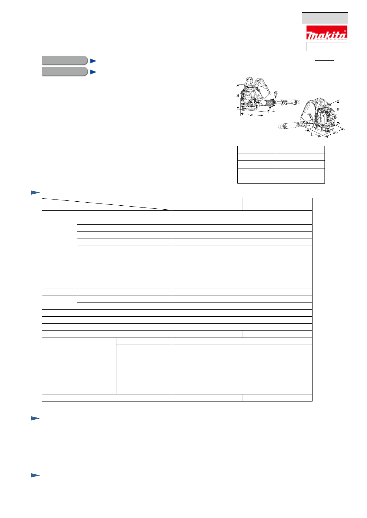
Dimensions: mm (“)
Length (L)
332 (13-1/8)
Width 1 (W1)
460 (18-1/8)
Width 2 (W2)
510 (20)
Height (H)
480 (18-7/8)
Model
Specification
4-stroke, single-cy linder, air-cooled
(Makita EH075F1)
Displacement: cm³ (cu.in)
75.6 (4.6)
Fuel
Straight u nleaded g asolin e*1 (E 0 to E10* 2)
Max output: kW (PS)
2.7 (3.7) [at 7,000 minˉ¹]
Max torque: N.m
4.4 [at 5,000 minˉ¹]
at max out put pow er
7,100
at no load
2,800
SAE10W-30,
(4-stroke eng ine oil for automobile)
Carburetor
Diaphragm
Starting
system
Easy start (Spring-assisted recoil starter)
No
Decompression valve
Yes
Spark plug
NGK CMR6A
Primer pump
Yes
Fuel tank capacity: L (US oz )
1.9 (64)
Throttle location
Tube-mounted
Hip-mounted
End nozzle 90-60
89 (200)
End nozzle 90-70
81 (181)
End nozzle 90-60
90 (201)
End nozzle 90-70
81 (182)
End nozzle 90-60
17 (607)
End nozzle 90-70
19 (682)
End nozzle 90-60
17 (611)
End nozzle 90-70
19 (682)
Dry weight: kg (lbs)
10.8 (23.8)
11.0 (24.3)
T
ECHNICAL INFORMATION
July 2015
OFFICIAL USE
for A SC & Sales Shop
P 1 /35
PRODUCT
Petrol Blower
CONCEPT AND MAIN APPLICA TIONS
Model No.
Description
S
S
O
EB7650TH/
EB7650THG
EB7650WH
EB7650TH/ EB7650THG/ EB7650WH
Models EB7650 TH/ EB7650TH G/ EB7650WH a re Petrol blow ers equip ped wit h
75.6cm³ 4-stroke engine in compliance with strict exhaust emission regulations.
These products are ideal for professional use with the following features:
• Higher air speed and larger air volume than our current model BBX7600
for excellent operation effici ency
• 4 damper springs mou nted between t he engine and the b ackpack fram e
that reduce vibration on the back of operator even during long hours
of operation t o redu ce opera tor st ress an d fatig ue
• Cushioning back padding and shoulder straps well-ventilated for effective
sweat evaporati on to provide m ore comf ort
Model EB7650TH features tube-mounted throttle while EB7650WH features
hip-mounted throttle. Model EB7650THG is E25 compatible.
pecification
EB7650TH/ EB 7650THG EB7650WH
Type
Engine
Speed: minˉ¹ = rpm
Engine oil
Max air
speed:
m/s*3
Max air
volume:
m³/min*3
*1 "Straight" means "not mixed with engine oil". *2 EB7650THG: E25 *3 Actual m easured value
tandard equi pment
Oil bottle set*4 Flexible pipe End nozzle 90-60 Long pipe 90
Box wrench 16 Swivel pipe End nozzle 90-70
Driver Hose clamp Flat nozzle 90
*4 W ith engine oil contained for some countries.
Note: The standard equipment may vary by country or model variation.
ptional accessories
Short pipe 90 Hip belt set
Long pipe 90
Short pipe 9 0
Long pipe 90
Short pipe 9 0
Class SF or higher of A PI Classification
Page 2

P 2/ 35
Repair
CAUTION: R epair the mach ine in acco rdance with “Ins tructio n manual” or “Safety instructions”.
Index
[1] NECESSARY REPAIRING T OOLS P 2
[2] GASKETS AND LUBRICA TION P 3
[3] DISASSEMB LY/ASSEM BLY P 4-28
[3]-1. W arning P 4
[3]-2. Blower Section (Band Completes L and R, Frame and Fan) P 4-9
[3]-3. Throttle Lever Section P 10-12
[3]-4. Engine Section (Rocker Arm, Valve Portion, and Cam gear Portion) P 13-17
[3]-5. Air Cleaner Case P 17
[3]-6. Carburetor P 18-20
[3]-7. Flywheel P 21
[3]-8. Ignition System P 21-22
[3]-9. Crankcase P 23-27
[3]-10. Completion Inspection Che ck Poi nts P 28
[1] NECESSARY REPAIRING T OOLS
Code No. Description Use for
1R005 Retaining ring pliers R T -2N Attaching/removing Cot ter (u sed tog ether w ith 1R 389)
1R070 Tachometer Engin e speed check
1R181 Ignition checker Diagnosis of Ignition coil
1R229 1/4” hex. Shank bit for M5 Loosening/tightening M5 Hex socket head bolts
1R288 Screwdriver magnetizer Attaching/removing Cotter
1R306 Ring spring removing jig Attaching/removing Cotter
1R311 Retaining ring pliers Removing/inserting tubes
1R364 Flywheel puller Removing Flywheel
1R366 Feeler gauge set Adjusting gaps of Spark plug, Rocker arm, an d Ignition coil
1R389 Cotter removal attachment Attaching/removing Cot ter (u sed tog ether w ith 1R 005)
1R402-A Digital tester Diagnosis of Ignition coil
Makita Corporation
Page 3
P 3/ 35
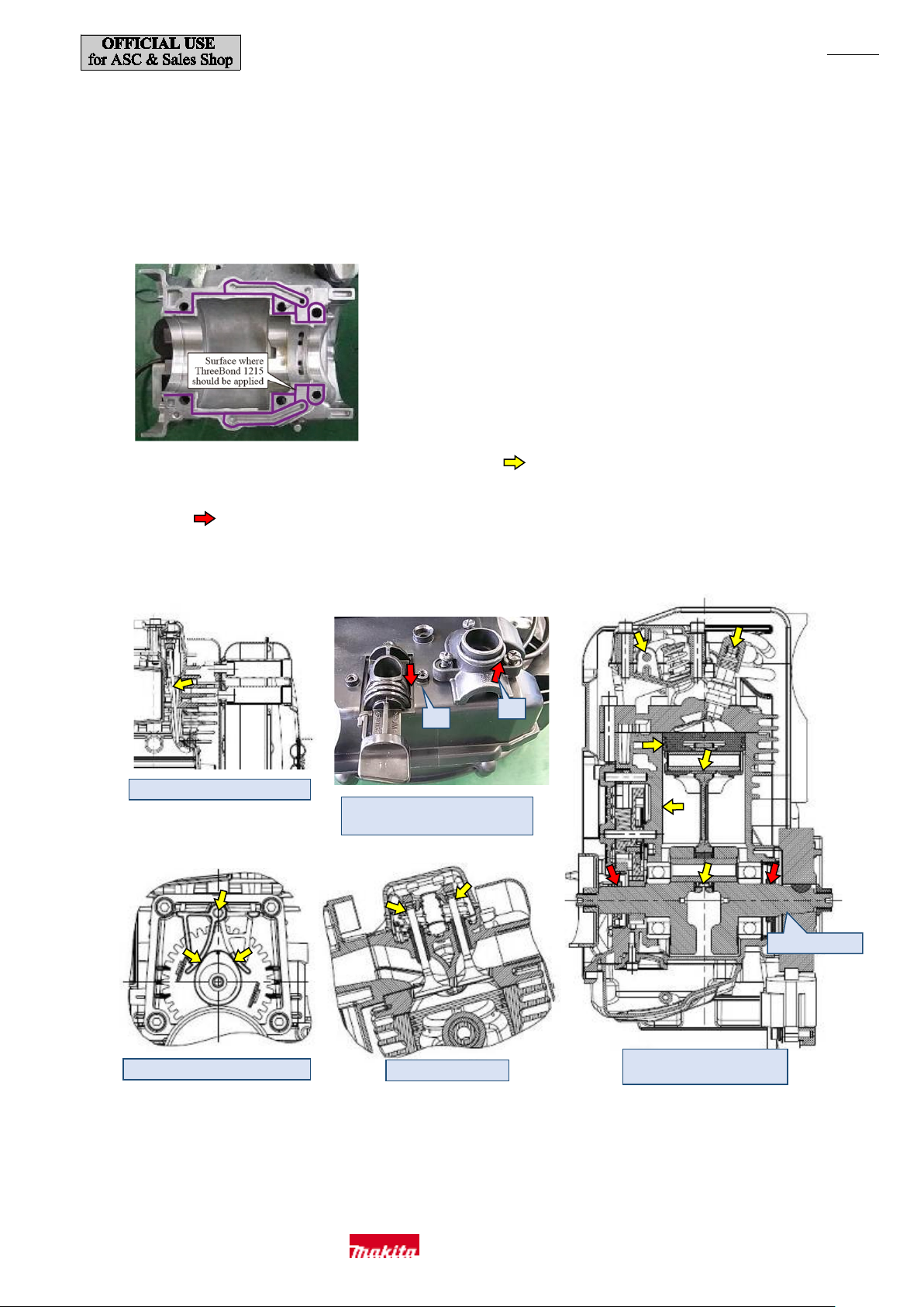
Tips of valves
Outer circumference of Cam lifter
Outer circumference of Push rods
Outer circumference of O-rings 17
17
20
Remove grease.
Sliding part s inside the engine
Sealing lips of Oil seals
[2] GASKETS AND LUBRICA TION
・After removing the gasket s, completely remove any residue.
・When reassembling, replace the gaskets with new ones.
・Use parts cleaner or the li ke to rem ove grease from the mating surface of Cylinder and Crankcase and then apply Liqu id gasket
ThreeBond 1215 as drawn below
.
・Apply a small amount of 4-s troke engine oil to each part in dicated by in the following diagrams when assembling the parts.
・Apply Makita grease N No.2 to the sealing lips of Oil seals and outer circumf erence of O rings 17 and 20 of the anti-icing valve portion
indicated by .
・Apply Makita grease N No.2 to the outer circumferen ce of the O ring of Elbow.
・When attaching Flywheel, use parts clean er or the lik e to remov e the grease from the tapered part.
and 20 of the anti-icing valve p ortion
Makita Corporation
Page 4
P 4/ 35
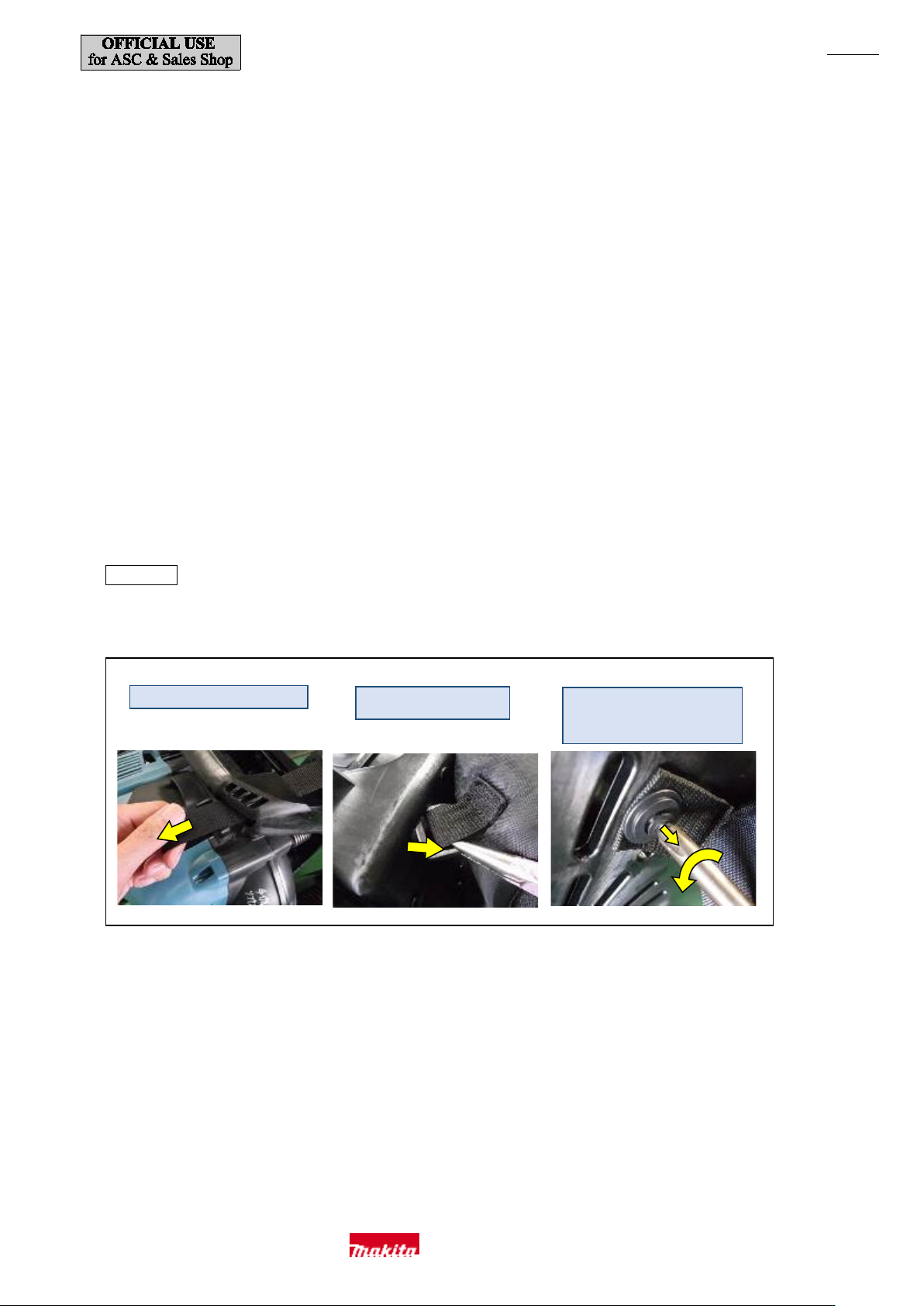
Fig. 1
Pull out the band as shown above.
Position the buck le vertica lly
and then remove it.
Turn t he ce nter of Lock rivet with
a Phillips scr ewdriv er to loose n it a
[3] DISASSEMB LY/ASSEM BLY
[3]-1. W arning
・There is a risk of a burn injury immediately after the engine is stopped. So wait until the engine has completely cooled
before performing the work.
・Completely remove all fuel from the inside of Fuel tank and Carburetor before performing the work. [No open flames]
・Remove the engine oil before performing the work.
・Perform the work on a solid workbench in a place where dust, dirt, etc. will not enter inside.
・Remember how and where the parts were assem bled when disas sembling th e product and take c are not to m ake a mis take
when assembling the product.
Prepare boxes so that you can store the parts in groups when disassembling the product.
・Handle the removed parts carefully and clean and w ash them properly.
・If a bolt or screw cann ot be loosened, do n ot apply excessive force. Use an impact d river or sim ilar tool.
・Be sure to tighten bolts and screws to the specified tightening torque values.
・After assembling the main parts, turn the engine by hand to check that there is no abnormality or looseness.
[3]-2. Blower Section (Band Completes L and R, Frame and Fan)
Disassembly
(1) Remove Band completes L and R and Hip belt. Remove each of the fixing parts as shown in Fig. 1.
little and then re move it.
Makita Corporation
Page 5
P 5/ 35
Fig. 4
Fig. 2
(a)
Fig. 3
(b)
(c)
Guard
(c)
Loosen this screw
only whe n remov ing
Fig. 5
Disconnect (e) from (f ).
(e)
2. Return Throttle
position a nd rem ove
1. Pull Throttle lev er
place with a finger.
(f)
Disconnect (e) from (d) a nd (g).
(d)
For Model EB7650WH,
(g)
Disconnec t the wire f rom the
M5-10 Hex nut
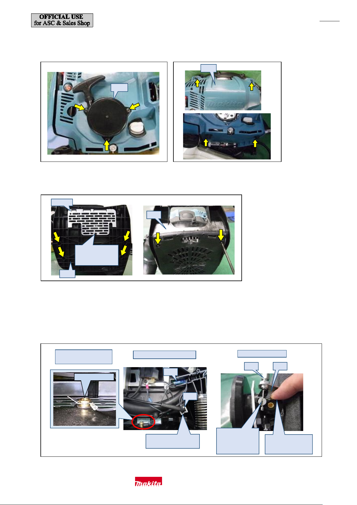
(2) Loosen three M5x20 Pan head screws and then remov e Recoil starter (a). (Fig. 2)
(3) Loosen f our 5x20 Tapping screws and then remove Engine cover (b). (Fig. 3)
(4) Remove six M5x16 Hex socket head bolts from th e bottom and front of Frame (c). (Fig. 4)
Guard.
(5) Lift up Fuel tank and disconnect the earth wire of Ignition coil from the brass M5-10 Hex nut beneath Fuel tank. (Left photo of Fig. 5)
(6) Disconnect Ignition coil at the bullet te rminals (d) (Center photo of Fig. 5), then disconnect Control cabl e (e) from Carburetor (f)
(Right photo of Fig. 5), and then rem ove the integrated Control cable (e) and Lead unit from Front volut e case (h). In th e case of
EB7650WH, remove Con trol ca ble (e) f rom Clip (g). (Center photo of Fig. 5)
earth terminal.
(7) Remove the engine, Volute case and Fuel tank together and then replace Frame (c).
lever to its or iginal
remove (e) from (g).
the wire end.
Makita Corporation
and then hold it in
Page 6
P 6/ 35
(j)
(i)
Fig. 6
3
(h)
2
1
4
(k)
Upper
Lower
Fig. 7
Fig. 8
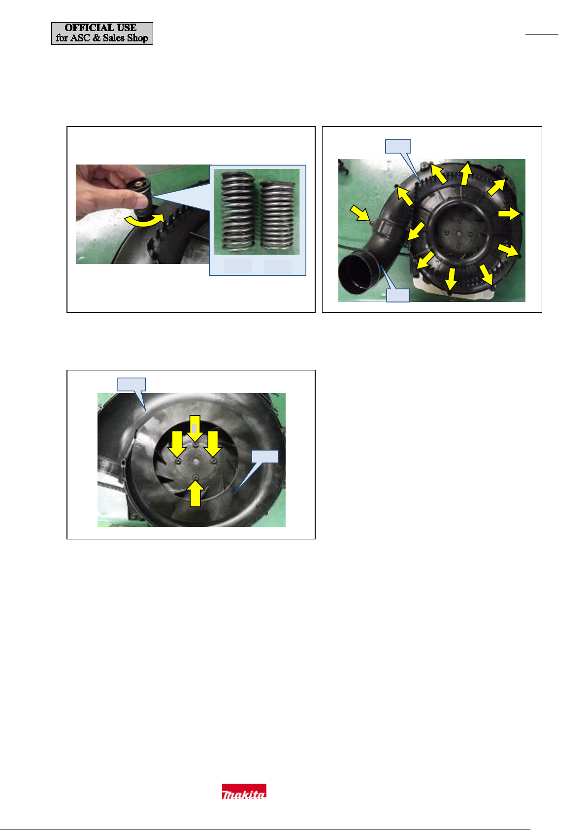
(8) Turn four Compression spri ngs 22 (the u pper tw o are sh orter than the lower two) used as vibration damper countercl ockwise and then
remove them. (Fig. 6)
(9) Loosen eleven 5x20 Tapping screws and then remove Rear volute case (i). Rem ove Elbow (j) together with it. (Fig. 7)
(10) Loosen the four M6x25 Hex socket head bolts and then remove fan (k). (Fig. 8)
Makita Corporation
Page 7

P 7/ 35
Protrusion
(b)
Slide Ru bber r ing all the w ay onto each
(a)
(c)
Place the bullet te rminals and
Fig. 9
Fig. 10
Assembly
(1) Tighten the four fan fixing screws in a criss-cross pattern (the order shown in Fig. 8).
(2) Screw Compression springs 22 all the way onto Spring holders. The two shorter ones should be at the top (of Rear volute cas e) and the
two longer on es shou ld be at the bottom (of Front volute case). (Fig. 6)
If Rubber rings at the bottom h ave been removed, att ach them as shown in the photo on the right of Fig. 9 and then screw the springs
onto Spring holders.
Spring hol der w ith the flang ed e nd of the
ring facing Front volute case.
(3) Attach Elbow (a) wit h the prot rusi on position ed as s how n in Fig. 9 so that you can rotate Elbow from the front
of the machine and then secure Rear volute case (b) with eleven Tapping screws 5. (Fig. 7)
(4) Attach Frame, then connect Carburetor to Control cable, then connect the bullet terminals and earth wire of
Ignition coil and then secure Guard. (Figs. 4 and 5)
Place the bullet terminals in place as shown in Fig. 5 (d) while taking care that it w ill not become pinched
in the engine cover. Place corrugated tube (c) of Model EB7650TH in place as shown in Fig. 10.
line filter in this space, if used.
Makita Corporation
Page 8
P 8/ 35
Left
Right
Twist 90 degrees
Carry out disassembly and assembly
he lever
Insert al ong the gui des
Recoil starter
Three M5x2 0
(d)
Oil guard:
Cylinder block
assembly
Choke lever
Four 5x20
Fig. 11
Fig. 12
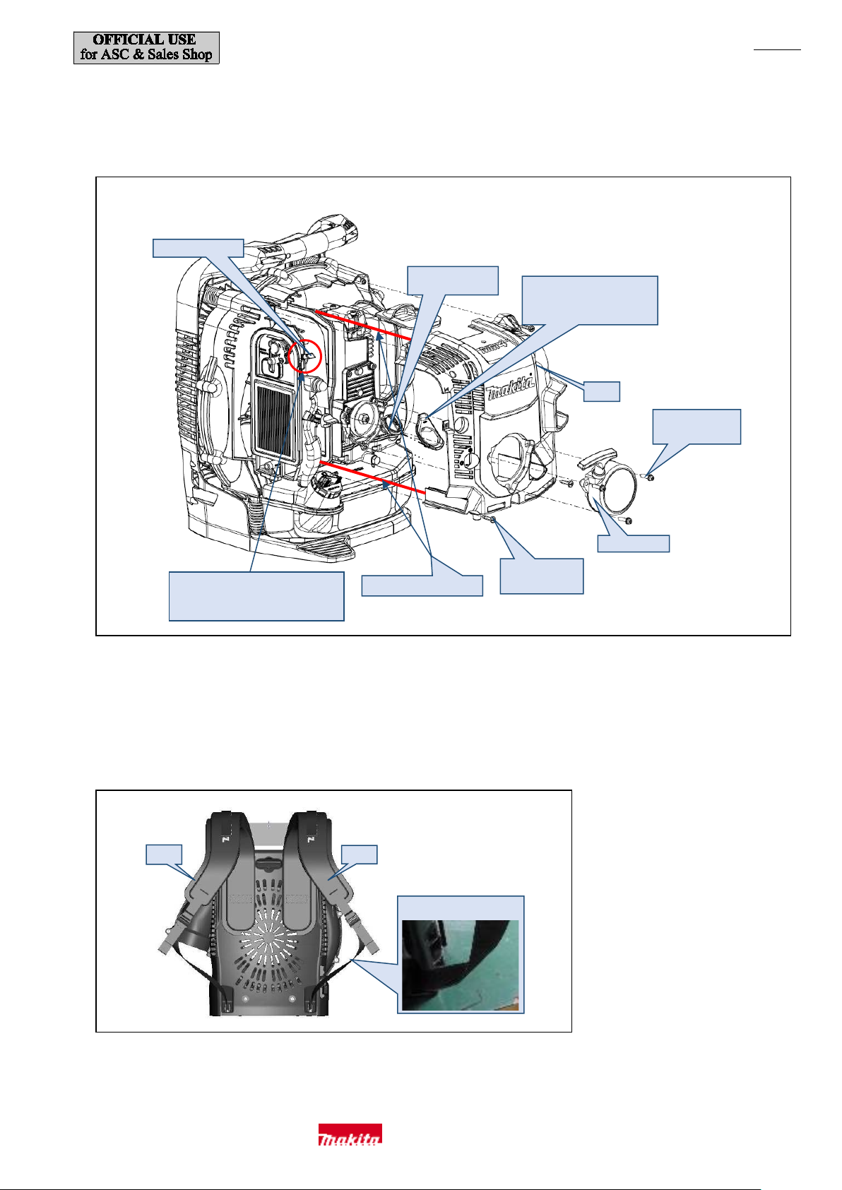
(5) When fitting Engine cover complete (d), f ollow the instructions described in Fig. 11. Make sure that Carburetor gasket is on the inner
side of the rib inside Engine cover complete and that Plug cover is not pinched.
Align the fixing screw boss positions and then fit the cover and secure it in place with the four screws. (Fig. 3)
Attach before f itting Engine
cover complete.
Pan head screws
(6) Secure Band completes L and R with the fixing parts by reversing the disassembly procedure shown in Fig. 1 while taking care not to mix
them up.
with Choke lever raised or t
will catch on the engine cover .
Tapping screws
Twist the bands; Band complete R by 90 degrees clockwis e and Band com plete L by 90 degrees counterclo ckwise viewed from the top,
and then attach them . (Fig. 12)
Makita Corporation
Page 9
P 9/ 35
Fuel tank
Coil spring 8
(e)
Slide (f) all the way
Spiral tube 6-100
Tube 3-370
(transpare nt bl ue)
Tube 3-370 (black)
Inside of Fuel Tank
Hose clamp
Filter
Tube 3-370
(black)
Tube 3-370
Slide (f) all the way
Fig. 13
Fig. 14
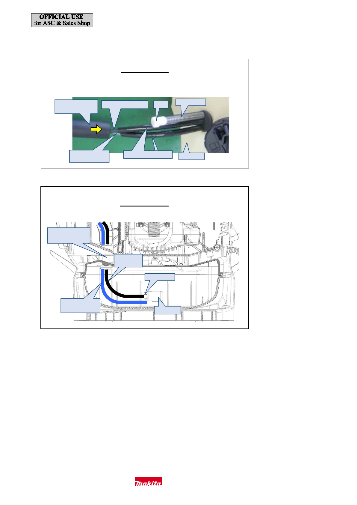
(7) When the tubes have been disconn ected from Fuel tank during disassembly, connect them as shown in Figs. 13 and 14.
Cover the two tubes coming out of Fuel tank, individually, with Spiral tube 6-100, then cover
the tube of Breather (e) w ith the coil spring 8 and then slide Tube guard 20-102 (f) all the way
to cover the tubes.
to cover the tubes.
Outside of Fuel T ank
to cover the tubes.
(transpare nt bl ue)
Makita Corporation
Page 10
P 10/ 35
(e)
(f) is on the back.
(a)
(b)
(d)
(c) (d)
Lever case L
Switch unit
Fig. 15
Fig. 16
[3]-3. Thr ottle Lever Section
EB7650TH
Disassembly
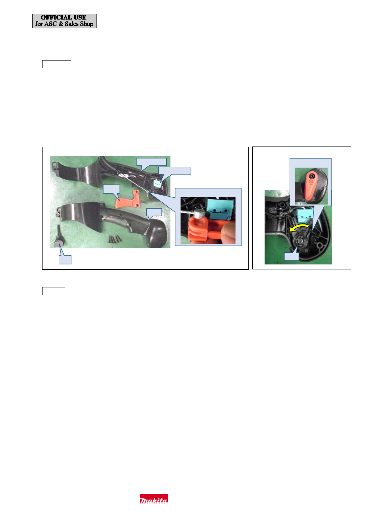
(1) Remove M5x30 thumb screw (a). (Fig. 15)
(2) Loosen five 4x18 Tapping screws and then remove Lever case R (b). (Fig. 15)
(3) Remove the h ead of Control cable (c) from Throttle lever A (d) and then remove the lever. (Fig. 15)
(4) Remove Throttle link (e), disconnect the connector of Switch unit, and then replace Switch unit.
(5) Loosen M 4x18 Hex socket head bolt and remove Throttle lever B (f). (Fig. 16)
Assembly
・Attach Throttle link (e) at the position shown in Fig. 16. First secure Throttle lever B (f) with the screw and then turn it counterclockwise
(viewed from the in side) to press the lever of Switch unit and then attach Throttle lever A (d).
Makita Corporation
Page 11
P 11/ 35
W ave washer 20
(a)
Remove (b).
Disconnect (c).
Pull out (d).
(e)
(f)
Tw o rubber sleeves 6
(h)
(g)
T wo tors ion s prings 21
(g)
Fig. 17
Fig. 18
Fig. 19
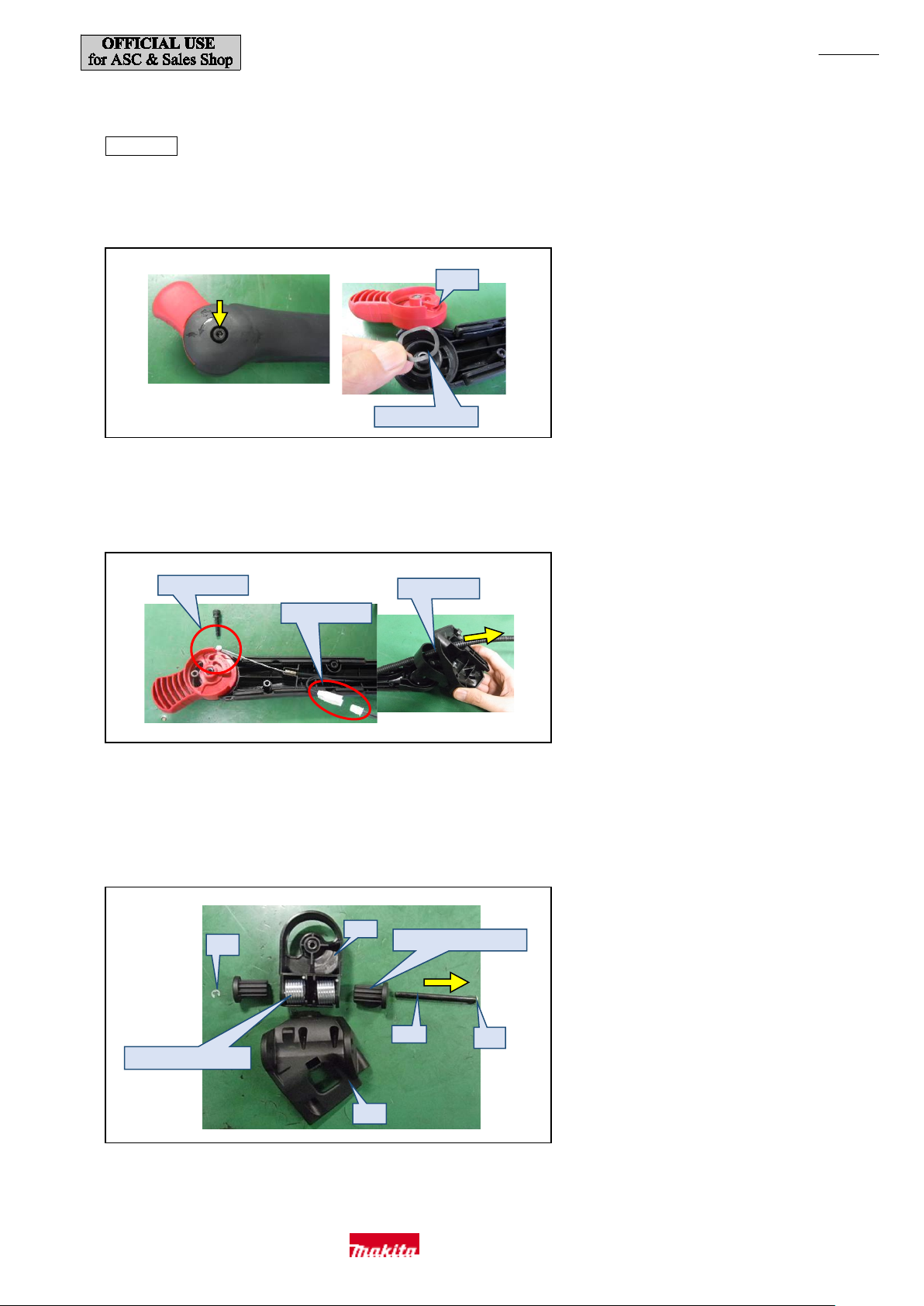
EB7650WH
Disassembly
(1) Loosen six 4x18 Tapping screws and then remove Arm cover.
(2) Loosen M 5x25 Hex socket head bolt and remove Throttle lever (a). (Fig. 17)
(3) Remove the h ead of Control cable (b) from Throttle lever (a), then disconnect the connecto r (c) of Stop sw itch wire and then pull out
Cont rol cable (b), Lead unit, and Corrugate d tube (d). (Fig. 18)
(4) Loosen M 6x25 Hex socket head bolt and then rem ove Arm base (e).
(5) Disassemble Arm base (e) and Arm base holde r (f) by rem oving on e of two E-4 Stop rings (g) and then pushing out Rod 6 (h) fr om th ere.
(Fig. 19)
Makita Corporation
Page 12
P 12/ 35
(a)
Connector
(e)
Switch unit
(f)
(f)
(c)
(b)
(d)
(g)
(b) and Flat washer 12
Fig. 20
Fig. 21
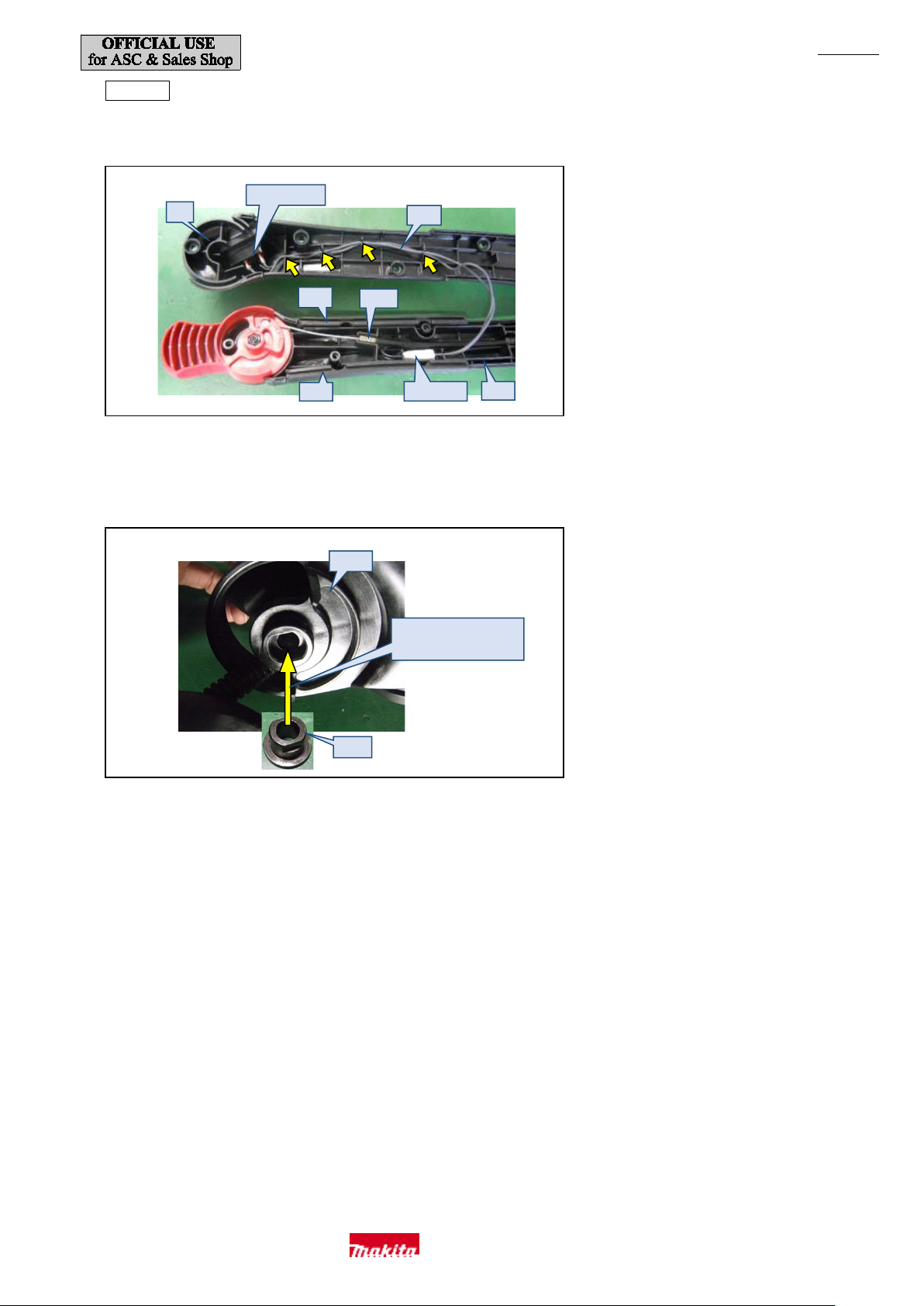
Assembly
(1) Fix Lead unit (a) in the lead wire holders of Arm (b) and Arm cover (c). (Fig. 20)
(2) Be sure to insert Wave washer 20 beneath Throttle lever. (Right photo of Fig. 17)
(3) Insert Sleeve 7 (d) into Arm base (g) while aligning the flats of the two parts . (Fig. 21)
go between (b) and (g).
(4) Pass Control cable (e), Lead unit (a), and Corrugated tube through at the position indicated in the right photo of Fig. 18.
(5) Insert Arm rubbers (f) (t hey are identical, and the orientation does not matter), and then attach Arm cover (c)
.
Makita Corporation
Page 13
P 13/ 35
(d)
(e)
(i)
(h)
(j)
(g)
(k)
(f)
(c)
(b)
Muffler
(a) 3 pcs .
Fig. 22
Fig. 23
Fig. 24
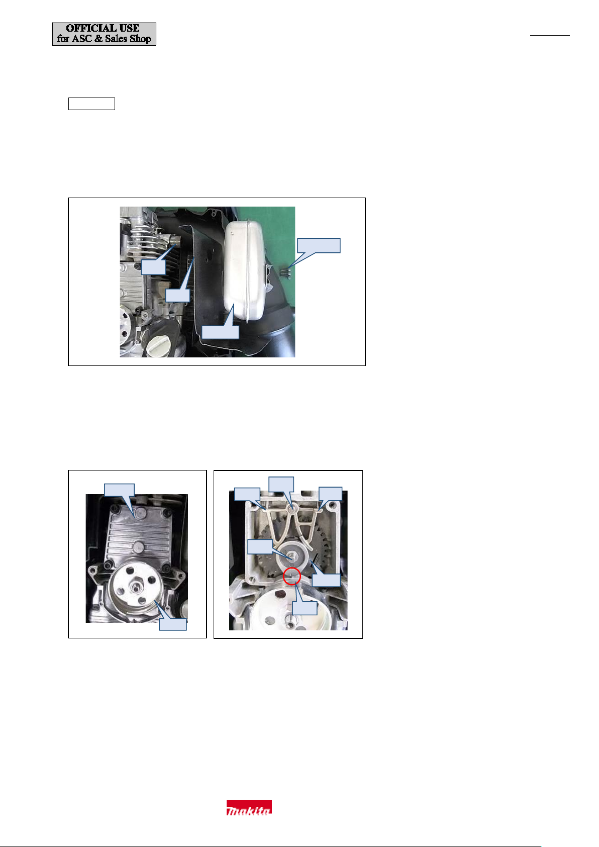
[3]-4. Engine Section (Rocker Arm , Valve Portion, and Camgear Portion)
* The blower section does not need to be disassembled when repairing Rocker arm and Camgear p ortions.
Disassembly
(1) Refer to "[3]-2. Blower Section (Band Completes L and R, Frame and Fan)" (page 4), then remove Recoil starter and Engine cover
and then disassemble Camgear portion. Leav e Frame attached.
(2) Remove three M6x18 Hex socket head bolts (a) and then remove Muffler gasket (b) and Exhaust port spacer (c). (Fig. 22)
(3) Refer to "[3]-6. Carburetor" (page 18) and then remove Carburetor.
(4) Remove Camgear cover (d). Do not rem ove Pulley (e) or you will have to turn the engine by hand. (Fig. 23)
(5) Turn Pulley (e) to align the alignm ent marks (f). Pull out Pin 5 used as cam lifter shaft [part No.256186-0] (g)
and remove Cam lifter L (h) and Cam lif ter R (i). (Fig. 24)
(6) Pull out pin 5 used as Camgear shaft [part No.256200-2] (j) and remove Camgear (k), and then check that the gear teeth and
counterweight portion are not damag ed.
Makita Corporation
Page 14
P 14/ 35
(q)
(r) 5 pcs.
Remove (p) first.
(o)
(o)
Do not loose n
this hex socke t head bol t.
Leave (l) inserted.
Do not remov e them.
1R311
(m)
(n)
Fig. 25
Fig. 26
Fig. 27
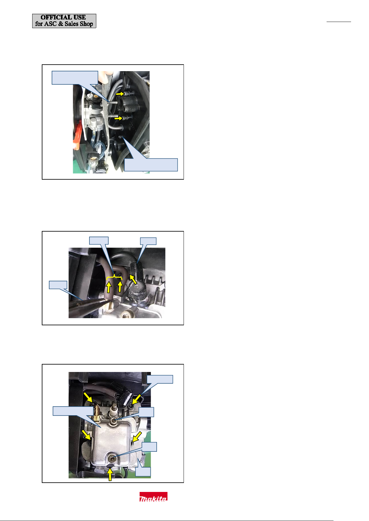
(7) Remove Air cleaner cover and Air cleaner element and then loosen two M5x60 Pan head screw s (l) securing Carburetor. (Fig. 51)
Do not remove them. Leave them inserted for easier assembling. (Fig. 25)
(8) Remove Air cleaner case and Carburetor and move them a little out of the way as shown in Fig. 25 and then remove two M5x25 Hex
socket head bolts securing Insulator with 1R229. At this time, do not loosen the lower hex socket head bolt. (Fig. 25)
(9) Remove Plug cap (m) and then disconnect the tw o tubes (n ) wit h 1R31 1. (Fig. 26)
(10) Loosen two M5x30 Hex socket head bolts (o) and rem ove Rocker cover complete (p). Loosen five M6x35 Socket head bolts (r) of
Cylin der head complete (q). (Fig. 27)
Makita Corporation
Page 15
P 15/ 35
(s)
(t)
(v)
1R389
1R005
(u)
Disassembly of Rocker arm is
Cy linder he ad
Retainer
(y)
(x)
(v) 4 pcs.
(w) 2 pcs.
Two Retainers
Exhaust port spacer
Fig. 28
Fig. 29
Fig. 30
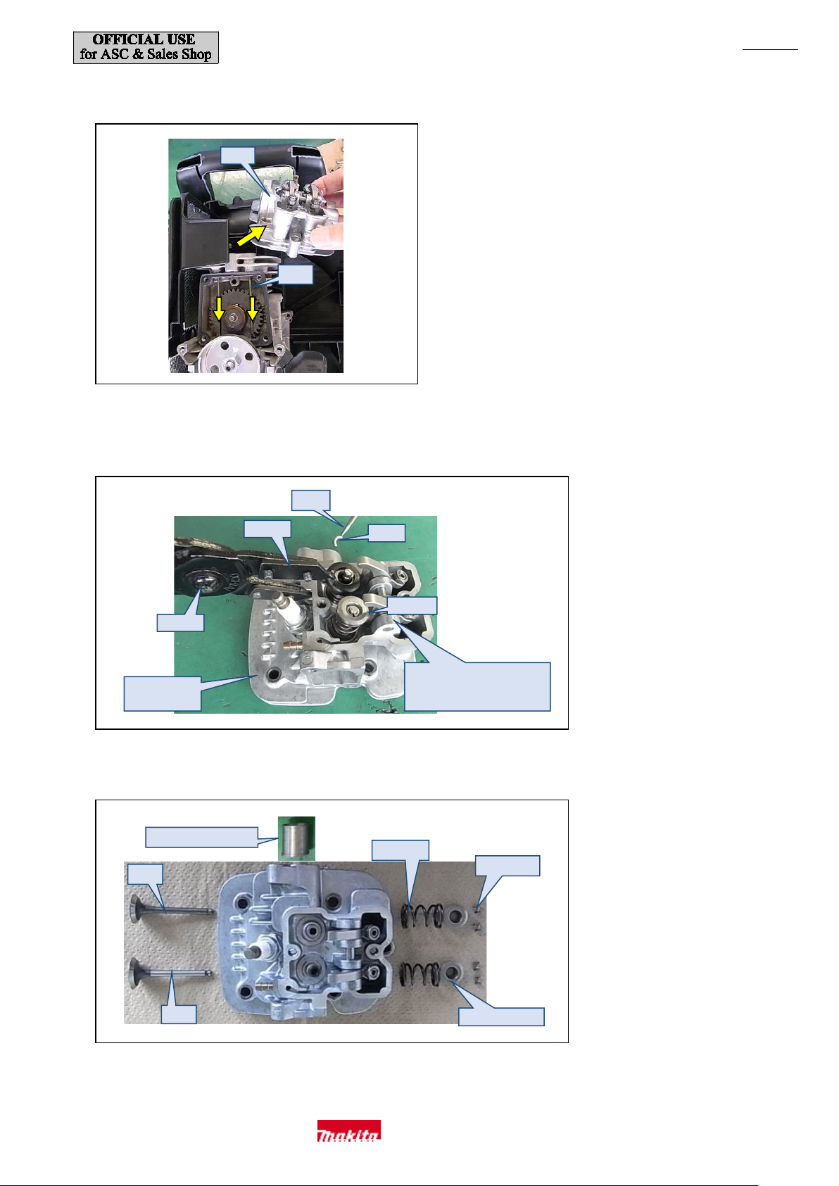
(11) Move Pusher rods (s) and remove Cylinder head complete (t). (Fig. 28)
(12) Push in Retainer w ith 1R389 an d 1R 005 to c ompres s Compression spring 11 (w) and remove Cotter (v) with a bit or the like (u)
magnetized with 1R288. (Fig. 29)
complete
prohibited. Replace Cylinder
head complete entirely.
(13) Remove Intake valve (x) and Exhaust valve (y) to replace or clean them . (Fig. 30)
Makita Corporation
Page 16
P 16/ 35
“N” on the north
pole of Flywheel
(a)
Ignition coil
Crankcase
Flywheel
(a)
(b1)
When turning Camgear by
(b2)
Fig. 31
Install so that the convex surface
Fig. 32
Fig. 33
Assembly
(1) Assemble the parts by reversing the disassembly procedure.
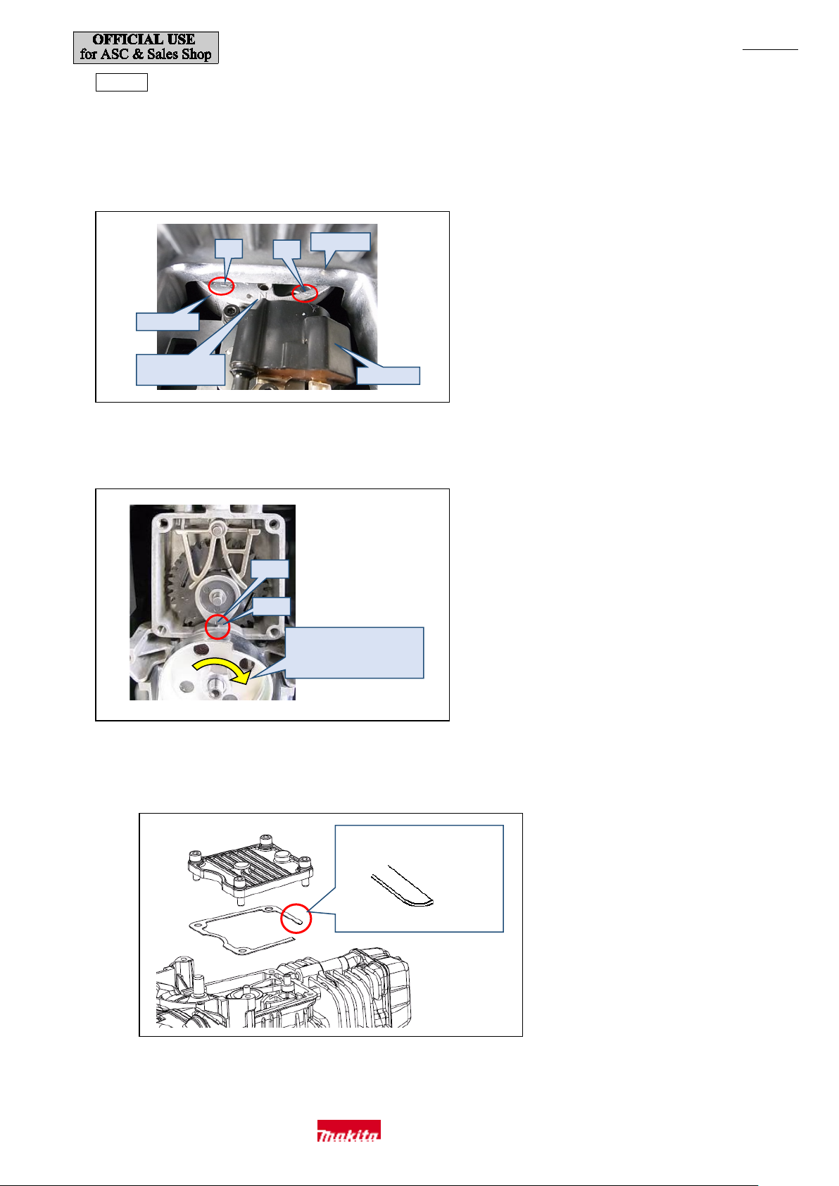
(2) Rotate Pulley to turn Crankshaft clockwise to align the alignment mark of two lines (a) on Flywheel so that they are parallel with the
surface of Crankcase. “N” on the north pole of Flywheel will be positioned directly below the surface of Crankcase. (Fig. 31)
(3) Align the alignment mark on Camgear (b1) and that of Crankcase (b2), then assemble them and then attach Cam gear cover . (Fig. 32)
hand, rotate Pulley in the
direction of the arr ow .
・Please note that the eng ine speed will not increase if even one of t he gear teeth is not aligned.
・Install the gasket so that t he conv ex surface is f acing the eng ine side. (Fig. 33)
・
is facing t he eng ine s ide.
Cross section of gasket
Makita Corporation
Page 17
P 17/ 35
(a)
(b)
(c)
(a)
(d)
(e)
M5 Hex nut
(c)
M5x9 Hex socket head screw
1R366
Fig. 34
Fig. 35
Fig. 36
Fig. 37
Fig. 38
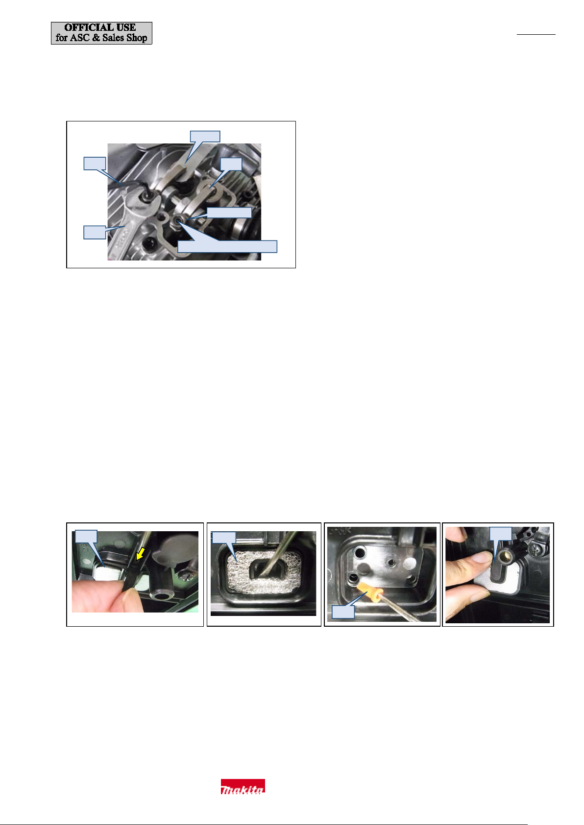
(4) Adjust the clearance between Rocker arm (c) and Valve with a wrench 8 (d) and a hex wrench 2.5 (e) so that it is 0.1 to 0.14 mm when
measured w ith 1R366 . (Fig. 34)
When tightening M5x9 Hex sock et head screw with (d), hold M5 He x nut with (e) to prevent it from rotating together with t he screw.
・Be sure to adjust the clearan ce after Camgear cover has been attac hed. If it is adjusted w ith the cover removed, Pin 5 used as Cam
lifter shaft [part No.256186-0] and Pin 5 used as Camgear shaft [part No.256200-2] will not be stable so the clearance w ill chang e
when the cover is attached after adjust ment.
(5) Turn Pulley clockwise by hand to rotate Crankshaft twice, check the gap, and then fully tighten. Confirm that a 0.15 mm leaf of the
feeler gauge cannot be inserted.
(6) Apply ThreeBond 1342 or Loctite 243 to three M6x18 Hex socket head bolts for securing Muffler and five M6x35 Socket hea d bolts for
securing Cylinder head complete when you re-tighten them because they are thread locking bolts.
[3]-5. Air Cleaner Case
(1) Pull the nozzle, insert a thin slotted screwdriver at the position shown in Fig. 35, and remov e Separator plate (a).
(2) Use the screwdriver in the same way to pull off Separator mesh (b). (Fig. 36)
(3) Loosen 3x10 Tapping screw and remove Separator case.
(4) Use an awl or similar tool to pull out Check valve (c). (Fig. 37) T a ke care not t o damage it .
(5) When installing Separator plate (a), tilt it first and then insert it as shown in Fig. 38.
Makita Corporation
Page 18
P 18/ 35
(I)
(P)
(O)
(F)
(G)
(H)
(Q)
(R)
(C)
(E)
(L)
(D)
(J)
(A)
(B)
(K)
(M)
(N)
(a)
(b)
(c)
Fig. 39
Fig. 40
[3]-6. Carburetor
Disassembly
(1) Refer to "[3]-2. Blower Section (Band Completes L and R, Frame and Fan)" (page 4) and then remove Engine cover complete and
disconnect Control c able fr om Carburetor.
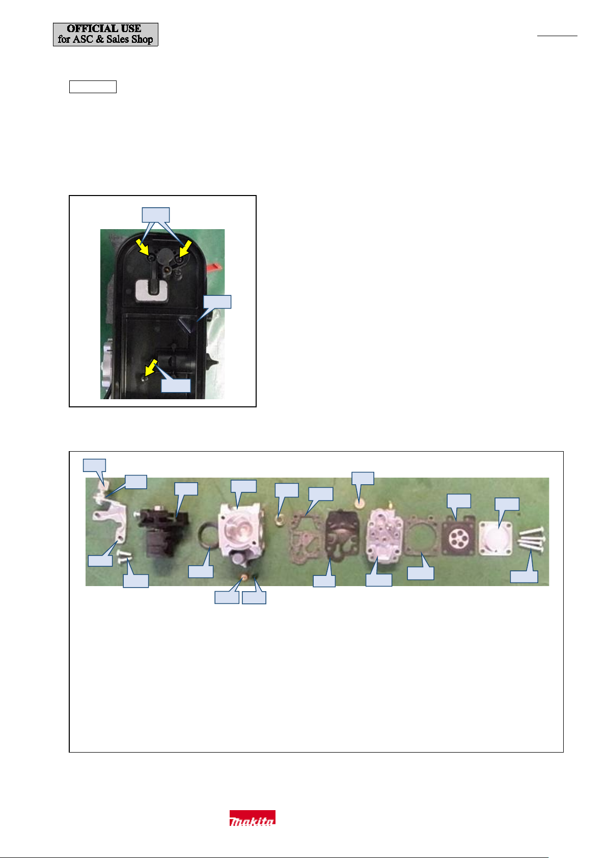
(2) Raise (close) Choke lever, then remove two M5x60 Pan head screws (b) and 5x20 Tapping screw (c) from Ai r cleaner case (a), then
disconnect the tubes, and then remove Air cleaner case and Carburetor. (Fig. 39)
(3) The Carburetor can be disassembled as shown in Fig. 40.
(A) Adjust screw (B) Cable adjust nut M6
(C) Throttle assembly (D) Carburetor
(E) Conical c ompre ssion s pring 5-9 (F) Pump gasket
(G) Inlet screen (H) Metering diaphragm
(I) Metering diaphragm cover (J) Cable bracket
(K) M3x10 pan head screw (2 pcs.) (L) Packing ring
(M) Main jet (N) O ring
(O) Pump diaphr agm (P) Pump body assembly
(Q) Metering diaphragm gasket (R) Screw (4 pcs.)
(4) Check the membrane around th e metal part of Metering diaphragm (H) and replace t he diaphragm if there is any deformation or
hardening.
Makita Corporation
Page 19
P 19/ 35
Rotor
Primer pump
Tube 3-370 (transparent),
Tube 3-60 (transparent),
Tube 3-370 (black),
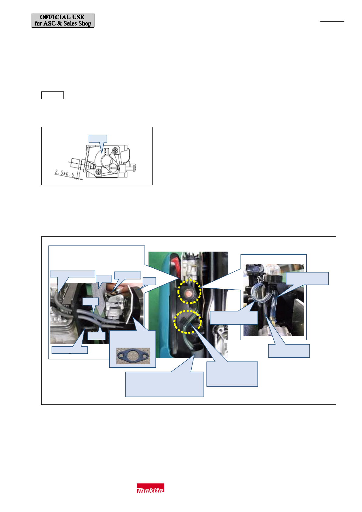
Connect the two black tubes to Air cleaner case (a) and
Branch
Single
(b)
Insert Carburetor gasket
(a)
Insert the two tubes in the
Carburetor
To Rocker arm chamber
To Cylinder s ide
For connecting tubes to Fuel tank,
Fig. 41
Fig. 42
(5) Also replace Pump diaphragm (O) if there is any deformation or hardening.
(6) Remove Inlet screen (G) while tak ing care not t o deform it an d then clean it with carburet or cleaner .
(7) Be sure to use carburetor cleaner to clean the m ain jet portion at t he center .
・Do not use air duster becau se parts such as Check valve may be damaged if they are cleaned w ith air duster .
(8) Replace Metering diaphragm gasket (Q) and Pump gasket (F) if possible when you disassemble Carburetor.
Assembly
(1) Make adjustment of Adjust screw for Cont rol cabl e as shown in Fig. 41.
(2) Check that Rotor contacts the stopper both at idling and full throttle and that the specified rotation speeds (refer to "[3]-10. Completion
Inspection Check Points" [page 28]) are achieved after assembly.
(3) Refer to Fig. 42 for the position to connect each tube to Carburetor.
pass the m thr oug h the cuto ut ho le in Carburetor gasket
(large) (b).
(small) here.
refer to assembly procedure 7 of "[3]-2.
Blower Sec tion (Ban d Completes L a nd
R, Fram e and Fan)" (page 12).
to Fuel tank
right rib. Place the black one
beneath the tra nspare nt one.
Do not use the left side.
to Carburetor
to Fuel tank
Makita Corporation
Page 20
P 20/ 35
The tubes shoul d
(b)
To Rocker arm chamber
The gap should be
1.0mm or l ess.
(c)
Orientation of (d) viewed f rom t he
Fig. 43
Fig. 44
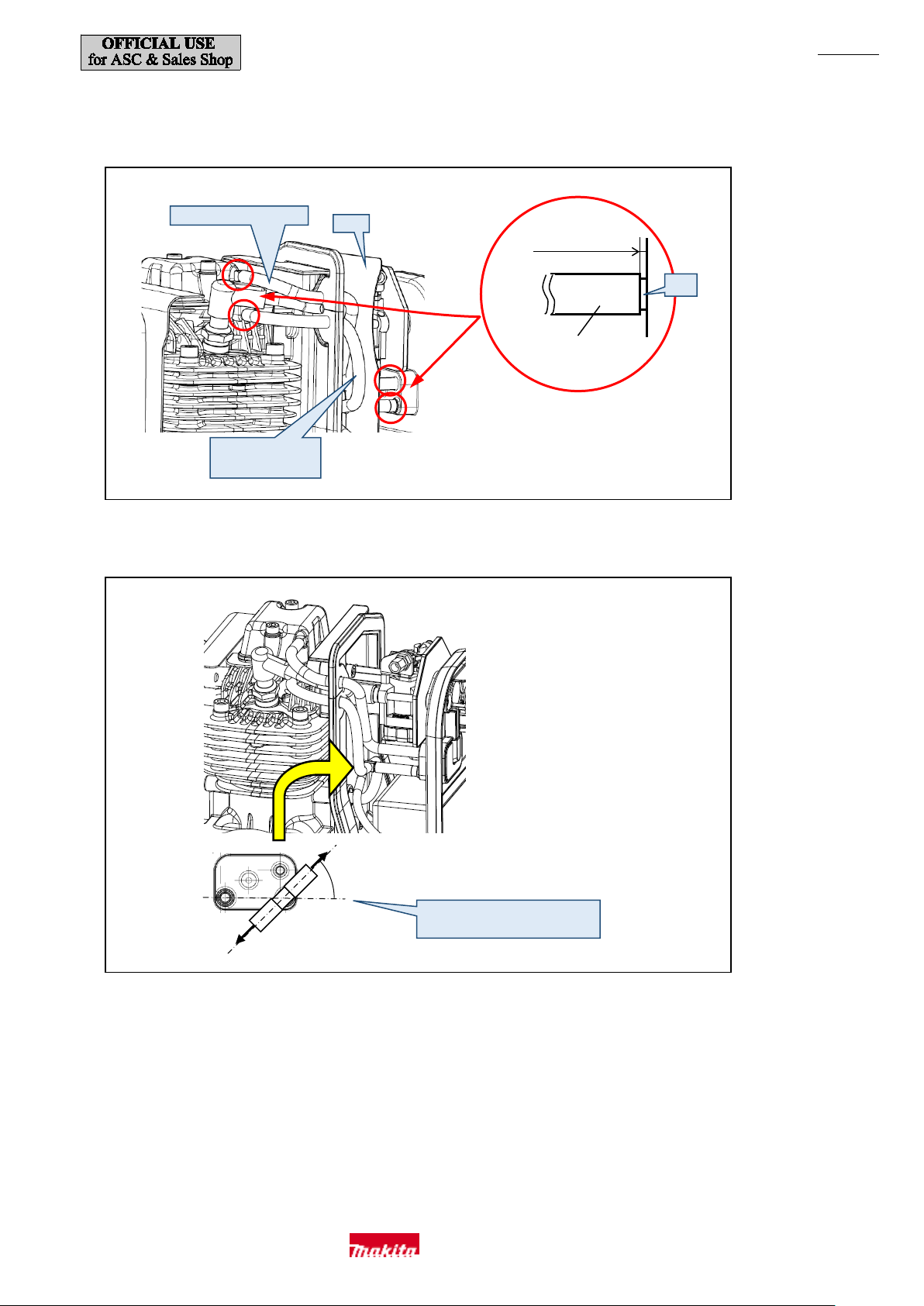
(4) Use 1R311 to slide the tubes all the way over the nipples (c) until they stop. (Fig. 43)
Make sure that the tubes are not pushing against Carburetor gasket (large) (b)
(5) Connect the tubes with Hose joint (d) oriented as shown in Fig. 44.
not push against (b).
.
1.0 mm or l ess
45 ゚±10 ゚
direction of the yellow arrow
Makita Corporation
Page 21
P 21/ 35
(a)
1R364
Temporarily
fasten (b).
Fig. 45
Fig. 46
[3]-7. Flywheel
Repair Flywheel while th e engine is separated from the blow er section.
Disassembly
(1) Refer to "[3]-2. Blower Section (Band Completes L and R, Frame and Fan)" (page 4) and "[3]-9. Crankcase" (page 23) and then
disassemble the blower section t o separate th e engine from the blower section.
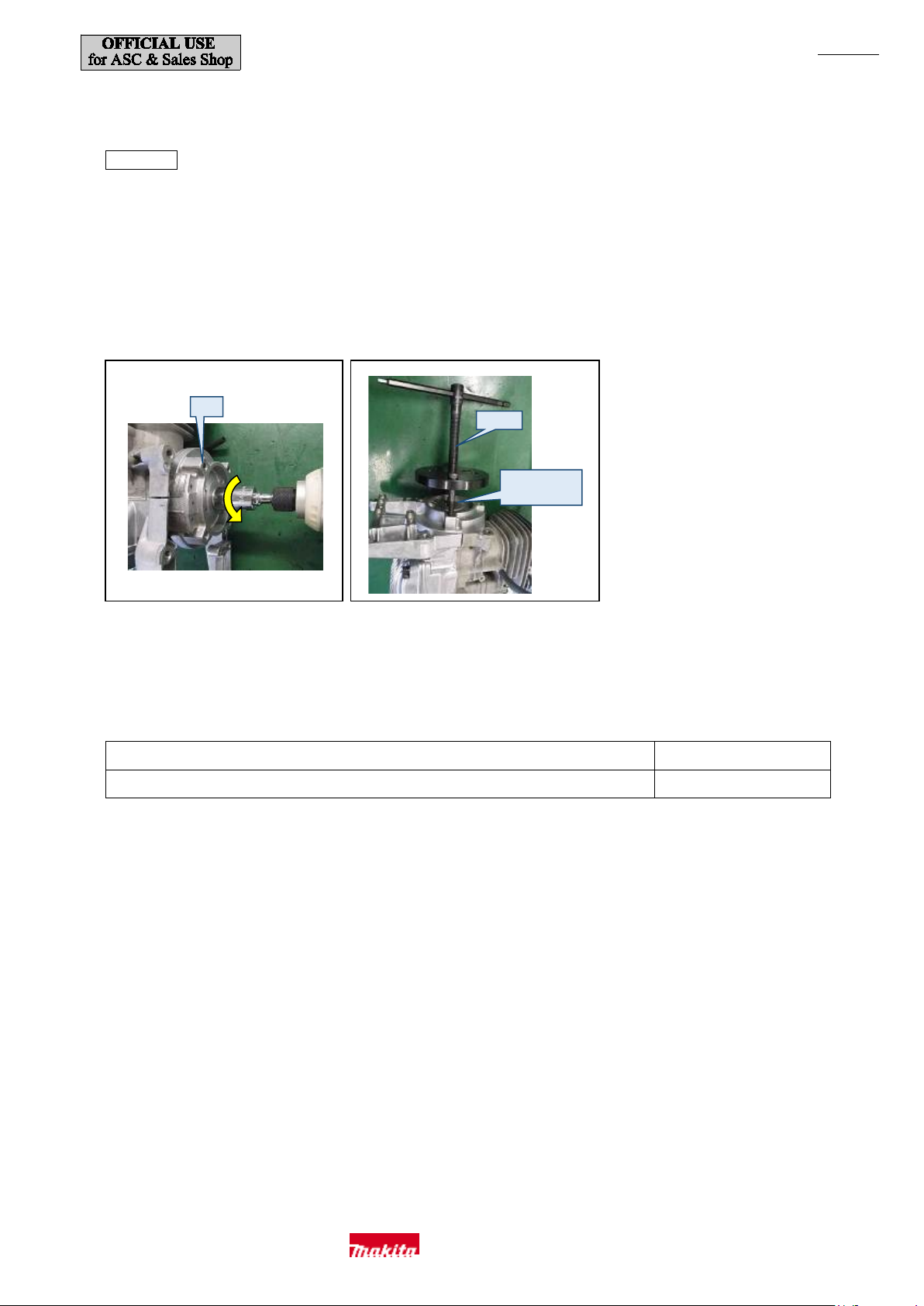
(2) Remove M10 Flange nut (right-handed) that is securing Flywheel (a) with a box bit 14 and an impact driver. (Fig. 45)
(3) Remove Flywheel with 1R364. Remove it while M10 Flange nut (b) is screwed onto Crankshaft so as to pr event deformati on of the
external (male) thread. Woodruff ke y 4 will come off so take care not to lose it. (Fig. 46)
[3]-8. Ignition System
Use 1R181 f or Ignition coil diagnosis. Refer t o page 24 of "Repair Tool List" for how to use the tool.
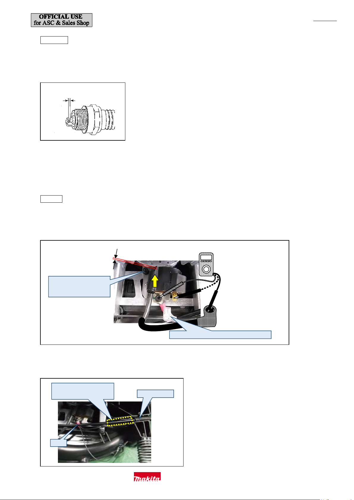
Disconnect the flag terminal of Stop switch and then, usin g 1R 402, check th e contin uity between earth an d the two places des cri bed bel ow.
The polarity of the tester does not matter . (Fig. 48)
Between the earth terminal and Plug cap spring (solid line side) 12 kΩ ±10%
Between the earth terminal and the tab terminal for Stop switch (dashed li ne side) 1.0 Ω
Makita Corporation
Page 22
P 22/ 35
While pushing towards (a),
ex
1R402
Disconnec t the flag terminal a nd test the continui ty .
0.3 mm
Fix in t his space.
Make sure they will not rise up.
Corrugate d tube
(b)
0.7 to 0.8 mm
Gap between the electrodes
Fig. 47
Fig. 48
Fig. 49
Disassembly
(1) Disconnect the secondary cabl e from Spark plug and then remove Spark plug.
(2) Check that the electrode gap is between 0.7 and 0.8 mm and that the electrodes and insulator are not contaminated or damaged. (Fig. 47)
(3) For replacement and adjustment of Ignition coil, refer to "[3]-2. Blower Section (Band Completes L and R, Frame and Fan)" (page
4) and then disassemble the blower section. Repair will be easier if you refer to "[3]-4. Engine Section (Rocker Arm, Valve Portion,
and Camgear Portion)" (page 13) and then separate the engine section from the blow er section.
(4) Remove Engine cover and Fuel tank and then remove Ig nition coil.
Assembly
(1) Align the positions of the magnet of Flywheel (a) and the iron c ore of Ignition coil and adjust the air gap with the 0.3 mm leaf of 1R366.
(Fig. 48)
tighten two M4x20 H
socket head bolts.
(2) Bend the lead wires of Stop switch an d earth terminal (b) towards the right and then secure them together to Ignition coil. (Fig. 49)
Makita Corporation
Page 23
P 23/ 35
(c)
(b)
Muffler
(a)
(d)
2
3
1
7
6 4 5
Fig. 50
Fig. 51
Fig. 52
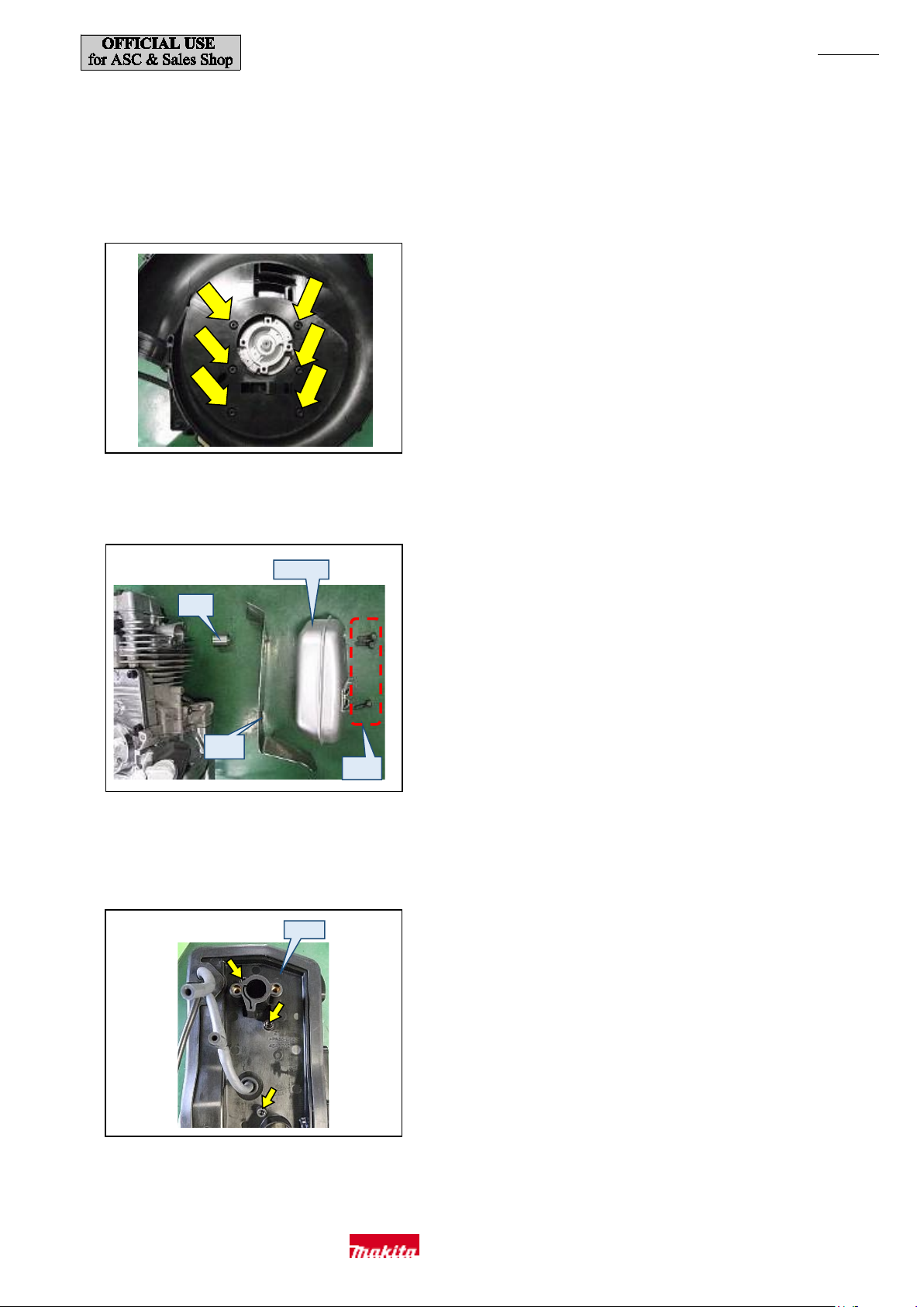
[3]-9. Crankcase
(1) Refer to "[3]-2. Blower Section (Band Completes L and R, Frame and Fan)" (page 4) an d then separate t he engine section from
Frame.
(2) Remove the six M6x25 Hex socket h ead bolts from Front volute case and then detach the engine block.
When assembling, tighten the bolts in the order shown in Fig. 50.
(3) Remove th ree M6x18 Hex socket head bolts (a) and then rem ove Muffler gasket (b) and Exhaust port spacer (c). (Fig. 51)
(4) Loosen t wo M5x25 Hex socket head bolts and on e M5x14 Hex socket head bolt (total of three bolts) an d remove Insulator complete (d).
(Fig. 52) For removing tubes, refer to "[3]-6. Carburetor" (page 18).
(5) Remove Pulley, Rocker cover complete, and Cylinder head complete.
Makita Corporation
Page 24
P 24/ 35
(h)
(g)
(f)
(e)
(l)
(k)
(j)
(i)
Fig. 53
Fig. 54
Fig. 55
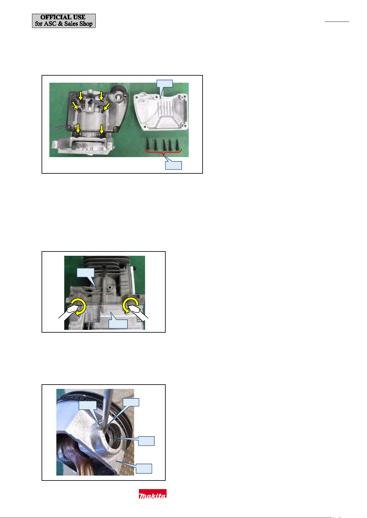
(6) When replacing Oil seal only, do n ot di sassem ble Cylinder block assembly but insert a slotted sc rewdriver in the lip portion of the inner
ring of Oil seal and pull it out. T ake car e not to dam age Cylinder.
(7) Remove five M5x25 Socket head bolts (e) from the bottom of the engine section and then remove Oil case (f). (Fig. 53)
(8) Remove four M6x30 Socket head bolts inside the oil cham ber and two M6x30 Socket head bolts outside th e oil cham ber and then
separate Cylinder block (g) and Crankcase (h). (Fig. 54)
Crankcase (h) is stuck to Cylinder block (g) with liquid gasket. Insert a slotted screwdriver into the four slots in the mating surface of
Cylinder block and Crankcase and turn it to pry them apart. Please not e that insertin g a slotted screwdriver into other than the slots may
result in damage
.
(9) Remove Crankshaft and Piston assembly and then replace Oil seals on the both ends of the shaft, Piston, and Piston rings.
(10) Pi ston (i) can be disassembled first by inserting a small slotted screwdriver or sim ilar tool in from the notch (j) shown in Fig. 55,
then by removi ng one of Ring springs 12 (k), and then pushing out Piston pin (l) from the other side.
Makita Corporation
Page 25
P 25/ 35
(C)
(D)
(E)
(A)
(G)
(F)
(L)
(M)
(I)
(B)
(H)
(J)
(K)
(a)
(b)
(c)
(d)
Fig. 56
Fig. 57
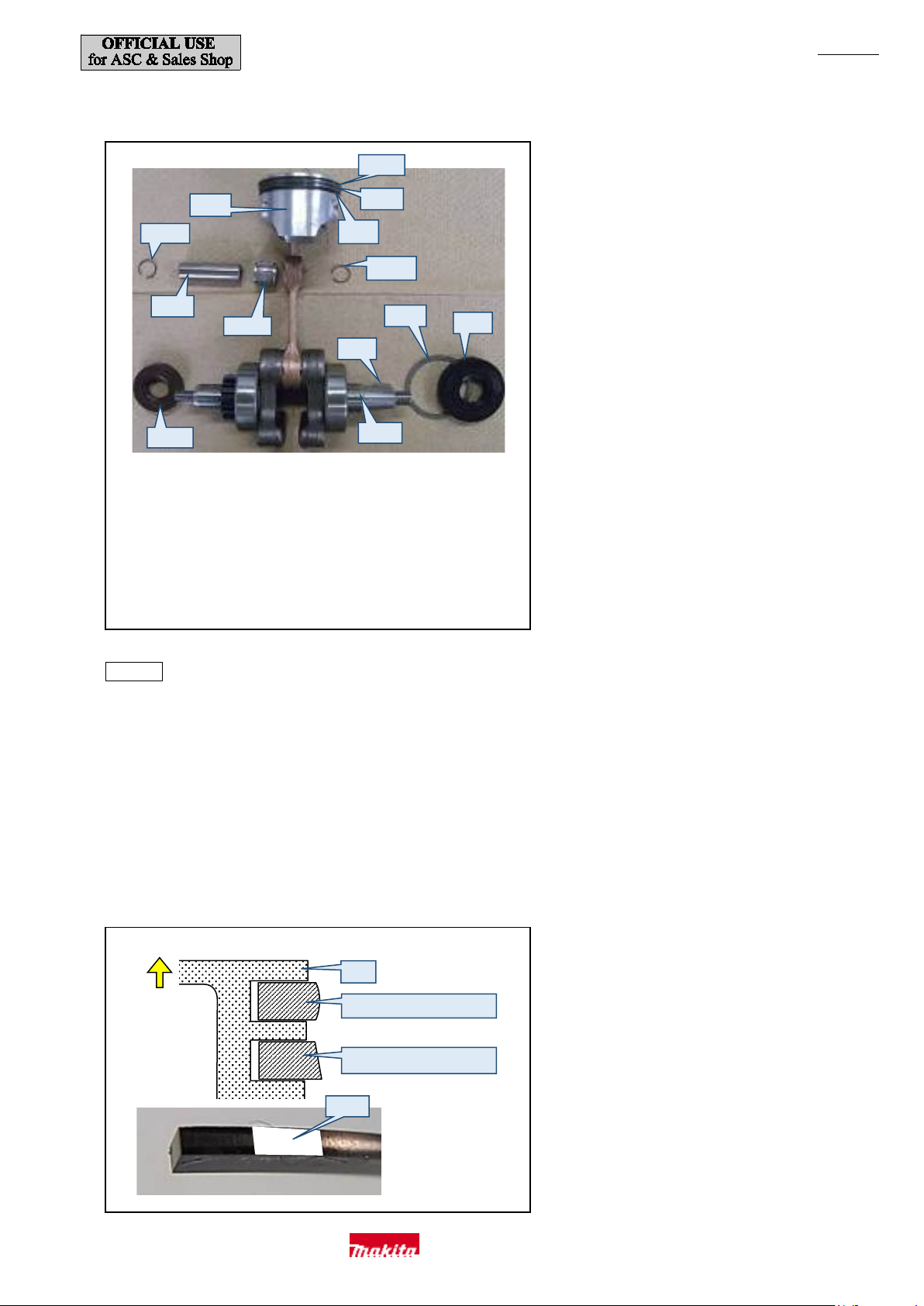
(11) The parts that can be replaced are show n in Fig. 56.
(A) Piston (B) Ring spring 12
Top ring (D) Second ring
(C)
(E) Oil ri ng (F) Ring spring 12
(G) Piston pin (H) Needle roller bearing
Woodruff key 4 (J) F lat washer 41
(I)
(K) Oil seal (L) (L) Oil seal 17
(M) Crankshaft complete
Assembly
(1) Assemble the parts by reversing the disassembly procedure.
(2) Top ring (b) and Second ring (c) of Piston (a) are dif ferent. T op ring (b) has a barrel face profile and has n o top a nd bott om as both sides
are the same. Second ri ng (c) has a taper face profile with larger bottom than top and so orientation matters. A ttach a new second ring so
that the white paint (d) mark comes to the side that is on the righ t when viewed from the side surface of Piston (a). (Fig. 57)
When inserting Piston into Cylinder:
・The gaps of Top ring (b) and Second ring (c) must be at 180 degrees to each other.
・The gaps of the three parts of Oil ring must be at 120 degree s to one another.
Up
with a barrel face profile
with a taper face profile
Makita Corporation
Page 26
P 26/ 35
(e)
(f)
(i)
(h)
(g)
Fig. 58
Fig. 59
Fig. 60
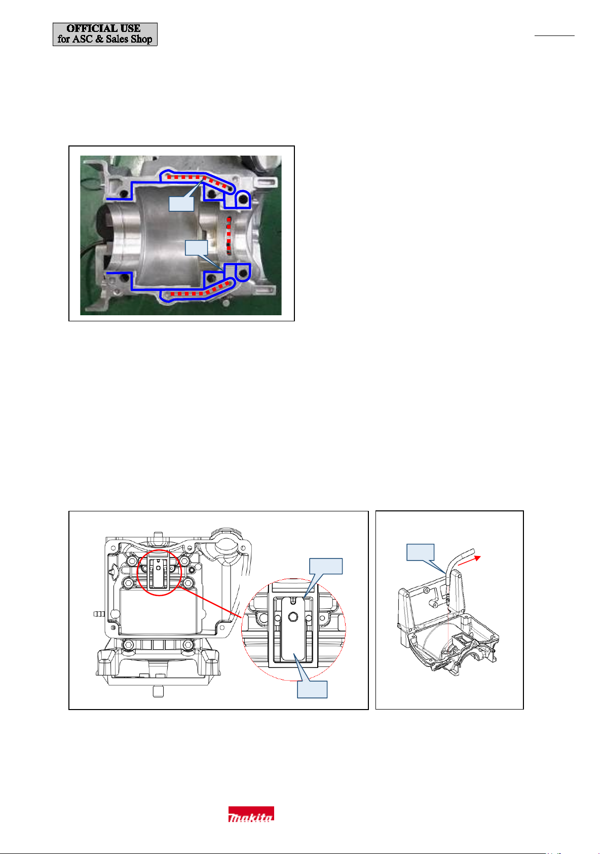
(3) When assembling Cylinder block and Crankcase, clean of f any residue of liqu id gasket from the mating surfaces and then remov e any
grease with parts cleaner. Apply a thin lay er of Liquid Gasket ThreeB ond 1215 to Crankcase and outer circumference of Oil seals, and
apply a thin layer to the parts indicated by solid lines (f) in Fig. 58 while avoiding the grooves indicated by the dashed lines (e) in Fig. 58
so as not to get any in the oil passages.
(4) Make sure that Exhaust port spacer is mounted on the muffler side of Cylinder head complete. Do not forget to mount it in place, and be
careful not to allow it to fall off in assembling Crankcase. (Fig. 51)
(5) Refer to "[3]-4. Engine Section ( Rocker Arm, Valve Portion, and Cam gear Portion)" (page 13) and then assem ble Camgear portion
and attach Camgear cover.
(6) Apply ThreeBond 1 342 or L octite 243 t o the th ree M 6x18 Hex socket head bolts for securing Muffler and the five M6x35 Hex socket
head bolts for securing Cylinder h ead complete when you re-tighten them because they are thread locking bolts.
(7) If Lead valve (g) inside Oil case has been removed, attach it s o that the n otch (h) is facing the oil filler opening. (Fig. 59)
(8) Bend Oil tube (i) to the lead v alve side. (Fig. 60)
(9) Attach Front volute case to the engine block and secure with the six M6x25 Hex socket head bolts. (Fig. 50)
Makita Corporation
Page 27
P 27/ 35
(n)
(o)
(k)
Triangular rib
(l)
Fits in groove
(j)
Control cable
(m)
Fig. 61
Fig. 62
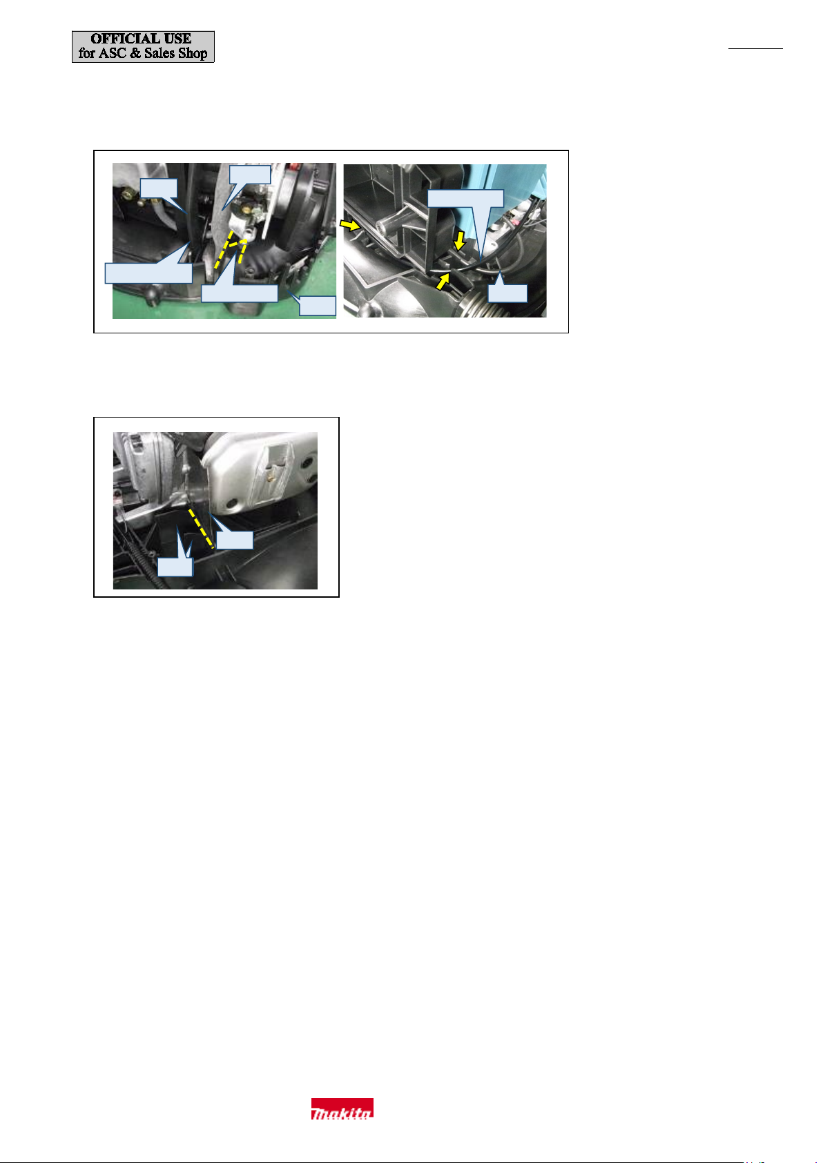
(10) When assembling Volute case (j) to Engine section, take care while routing Control cable and high voltage cable (m ) through the
grooves to ensure that Carburetor gasket (k) is in the position shown in Fig. 61 and Insulator complete (l) fits in the groove. (Fig. 61)
(11) Attach Muffler gasket (n) so that it is on the muf fler side of the rib (o) of Volute case as shown in Fig. 62.
(12) Connect Contr ol cabl e to Carburetor and connect the lead wire of Stop switch to Ignition coil.
(13) Insert Contr ol cabl e cor rugated t ube an d the bullet terminal in the storage space of Front volute case. For the s pecification with a line
filter, also insert Line filter and any slack wire in the storage space. (Fig. 10)
(14) For the tubes for connecting Fuel tank and Carburetor , attach eac h protector in reference to Fig. 42.
Makita Corporation
Page 28

P 28/ 35
[3]-10. Completion I nspect ion Chec k Point s
Measure the engine speed w ith 1R070 w hile Blower nozzle is attached.
Please note that the eng ine speed w ill not increase w hile th e nozzle is not attach ed.
(1) Are the parts, screws, and bolts installed properly?
(2) Does a cold engine start within five pulls of Recoil starter?
(3) Does the engine speed increase smoothly after idling for about 1 minute?
The engine speed should be 28 00 to 3 000 mi n-1 at idling and 7000 to 7200 min-1at maximum speed.
(4) Check that the rotor cont acts the stop per at both idling and full throttle and that the rotation speeds specified in the previous check point
are achieved after assem bly.
(5) Does Stop switch stop the engine properly?
(6) Does a warm engine start within three pulls of Recoil starter?
(7) Is there no Fuel or oil leak?
Makita Corporation
Page 29
C
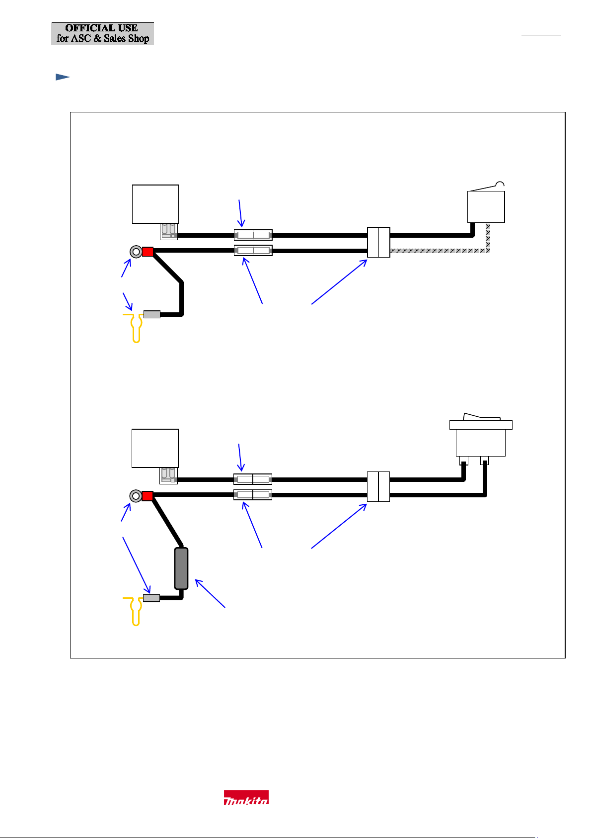
<EB7650TH>
Ignition coil
Switch unit
Earth terminal
Black
Black
Black
Black
Black
White
Black
Lead unit
Lead unit
Ignition coil
Switch unit
Earth terminal
Black
Black
Black
Black
Black
Black
Lead unit
Lead unit
1
1A
<EB7650WH>
Line filter
(if used)
Fig. D-1
ircuit diagram
P 29/ 35
黒
Makita Corporation
Page 30
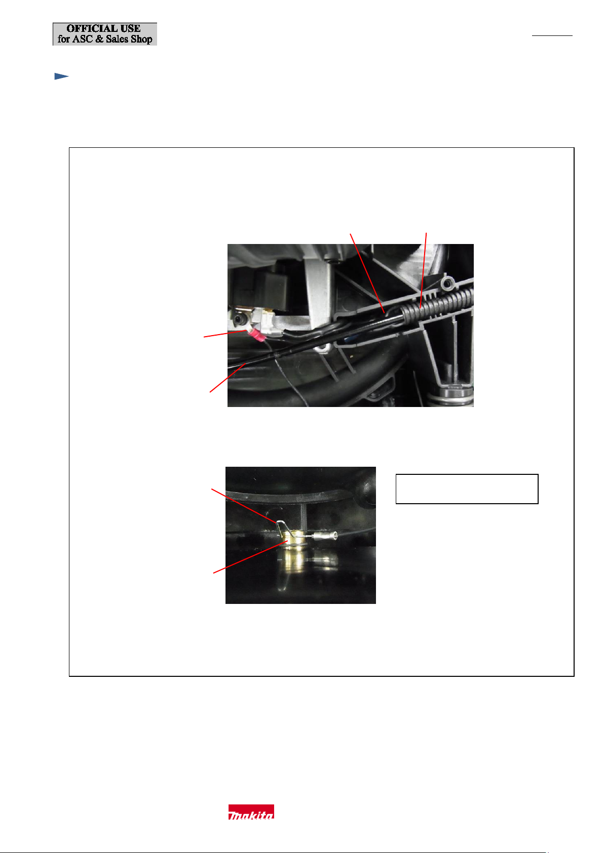
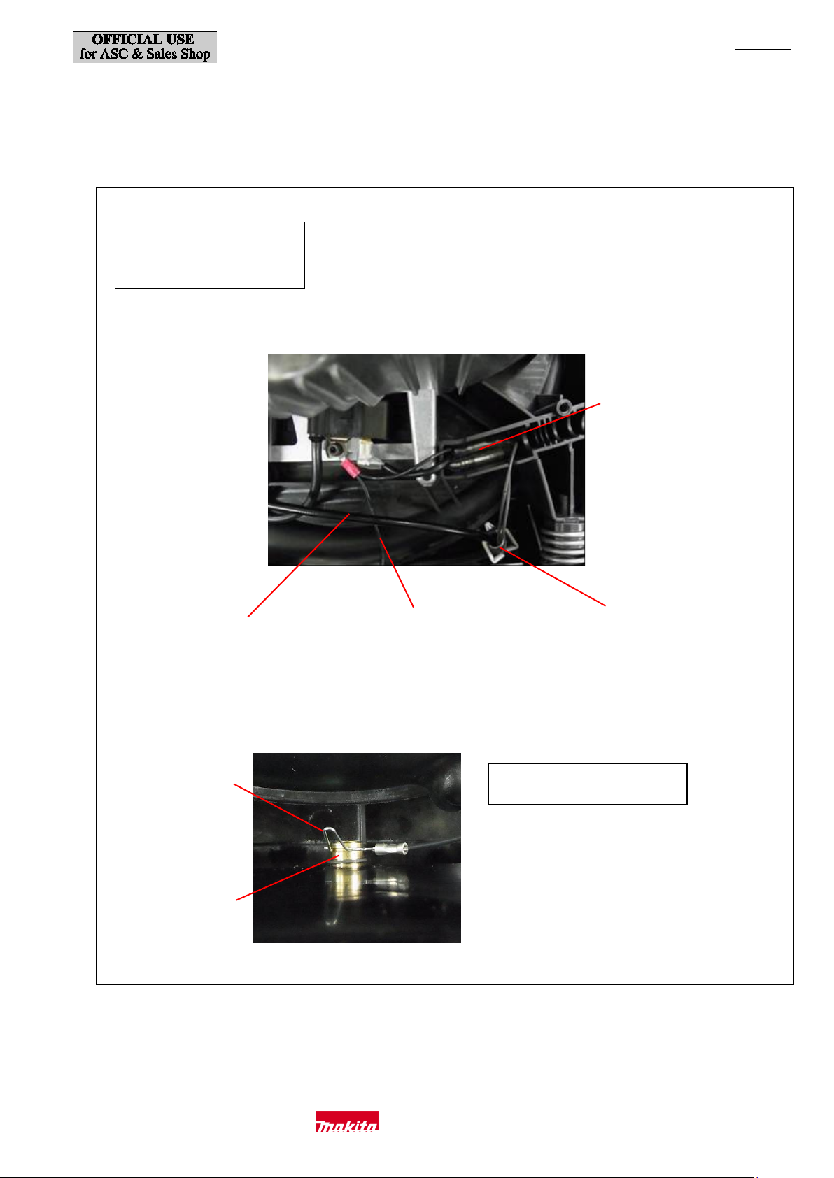
Fix Control cable and Lead unit in the groove of Front volute case.
<EB7650TH>
Earth termina
Control cable
Lead unit
Corrugated tube
Earth terminal
M5-10 Hex nut
Hook the earth terminal of Lead unit
W
Fig. D-2
iring diagram
P 30/ 35
l
in the groove of M5-10 Hex nut.
Makita Corporation
Page 31
P 31/ 35
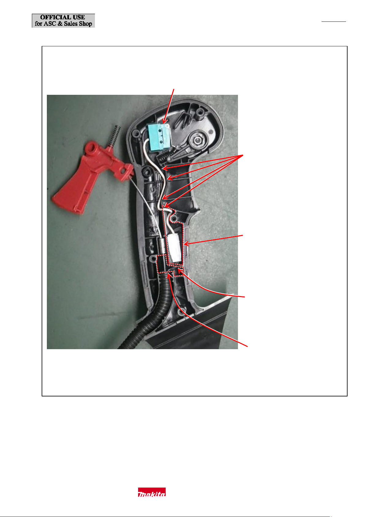
Fix the lead wires of Switch unit
Switch unit
Place Connectors and the slack of
Fix the lead wires of L ead unit
Place the slack of the l ead wires
Fig. D-3
(Stop switch)
in these lead w ire holders.
lead wires of lead unit in this space.
in this Lead wire holder.
of Lead unit in this space.
Makita Corporation
Page 32
<EB7650WH>
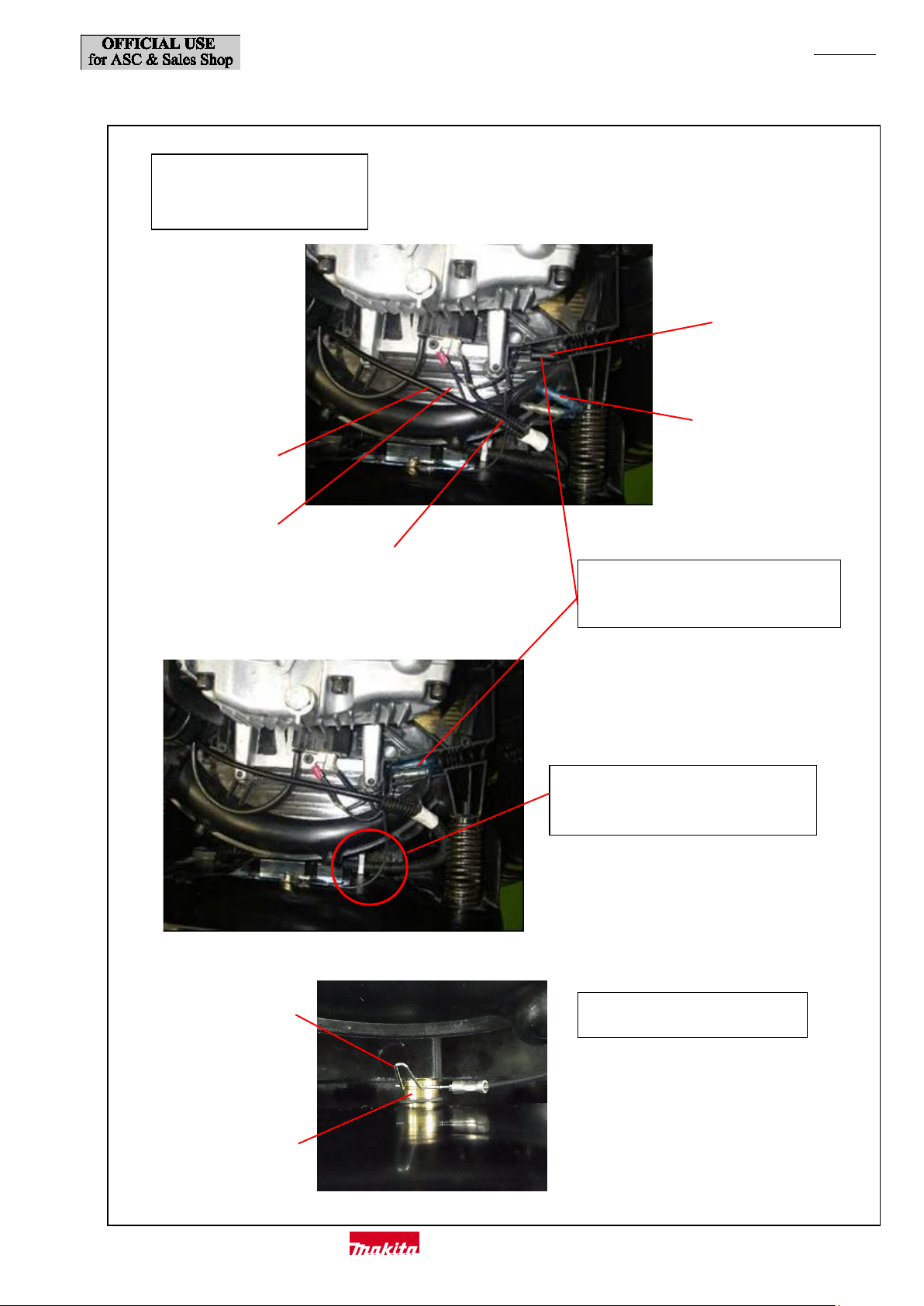
Fix Control cable and Lead unit in the groove of Front volute case. (Fig. D-4 or Fig. D-5)
Specifications without Line filter
by regulation)
Earth terminal
Lead unit
Corrugated tube
Control cable
Earth terminal
M5-10 Hex nut
Hook the earth terminal of Lead unit
Fig. D-4
(For countries and areas w here
noise suppr ession is not require d
P 32/ 35
Makita Corporation
in the groove of M5-10 Hex nut.
Page 33
P 33/ 35
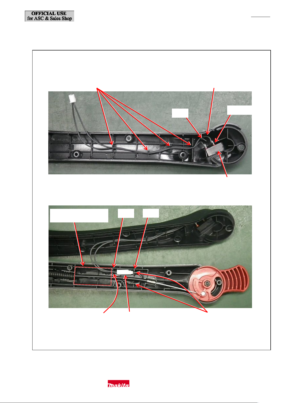
Specifications with Line filter
regulation)
Line filter
Earth termina
Lead unit
Corrugated tube
Control cable
Earth terminal
M5-10 Hex nut
Hook the earth terminal of Lead unit
Fig. D-5
(For countries and areas w here
noise suppression is required by
l
Place Line filter and the bullet terminals
in this space.
Allow the lead wire of Lead unit to have
some slack when routing it here.
in the groove of M5-10 Hex nut.
Makita Corporation
Page 34
P 34/ 35
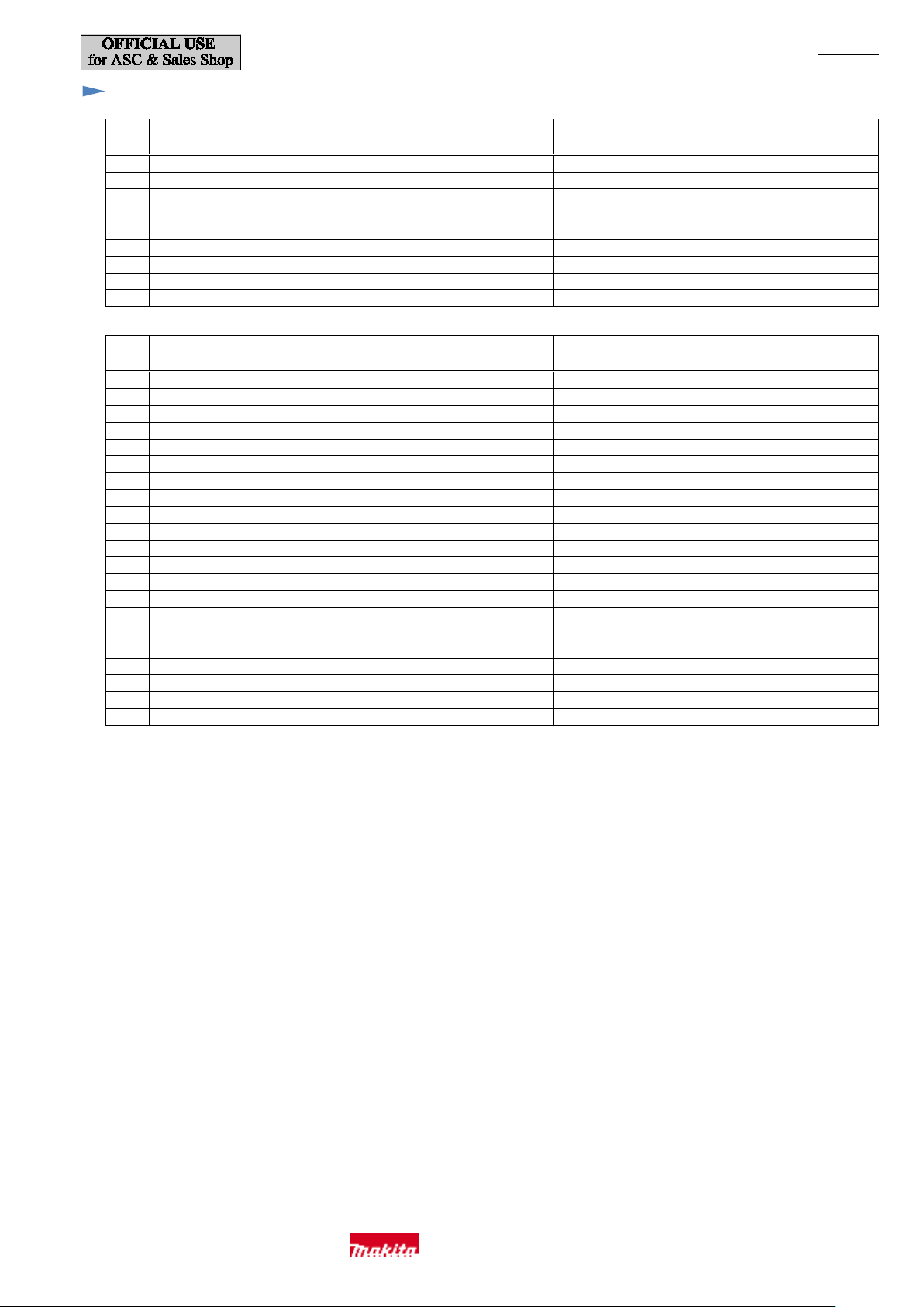
Switch unit
Fix the lead wires of Switch unit (Stop sw itch)
The lead wire of Switch unit (Stop switch)
Switch terminal 1
Rib A
Fix the lead wires of
Place Connectors between
Fix the lead wires of Switch unit
Rib B
Rib C
Place the slack of the l ead wires
Fig. D-6
connected t o Switch terminal 1 must be routed
in these lead wire holders.
between Rib A and the wall of A rm cover .
of Lead unit in this space.
(Stop switch) in this lead wire holder.
Rib B and Rib C.
(Stop switch)
Lead unit (Stop switch)
in these lead wire holders.
Makita Corporation
Page 35
Tightening tor que spec ificat ions
Tightening torque
[N・m]
1
Engine / Front volute case
8.0 - 10.0
M6×25 Hex socket head bolt WR
6
2
Fan 250/ Flywheel complete
8.0 - 10.0
M6×25 Hex socket head bolt WR
4 3 Throttle lever B/ Throttle link
1.5 - 1.7
M4×18 Hex socket head bolt
1 4 Arm/ T hrottle lever
0.8 - 1.2
M5×25 Hex socket head bolt WR
1 5 Arm/ Arm base
1.1 - 1.5
M6×25 Hex socket head bolt WR
1
6
Handle L/ Handle R
0.9 - 1.4
4×18 Tapping screw
3
7
Air cleaner cover/ Air cleaner case
0.9 - 1.2
M5×20 Thumb screw
2
8
Recoil/ Engine
2.5 - 4.0
M5×20 Pan head screw
3
9
Lever case L/ Lever case R
1.0 - 1.3
4×18 Tapping screw
5
Tightening torque
[N・m]
1
Crankcase / Cylin der
10.0 - 12.0
M6×30 Hex socket head bolt
6
2
Retainer plate/ Crankcase
2.0 – 3.5
M4×10 Hex socket head bolt SW
1
3
M8x12 Hex socket bolt (+ Gasket)/ Oil case
4.0 – 6.0
M8x12 Hex socket bolt t
1
4
Oil case/ Crankcase
4.5 – 6.5
M5×25 Hex socket head bolt W, SW
5
5
Cylinder he ad/ Cylinder
10.0 – 14.0
M6×35 Hex socket head bolt
5 6 Flywheel
35.0 – 40.0
M10 Nut
1
7
Ignition coil/ Crankcase
2.3 – 2.7
M4×20 Hex socket head bolt W, SW
2
8
Camgear cover/ Cylinder
4.5 – 6.5
M5×16 Hex socket head bolt WR
4
9
Rocker arm/ Adjust screw
4.0 – 5.5
M5 Nut
2
10
Rocker cover/ Cylinder head
4.5 – 6.5
M5×30 Hex socket head bolt WR
2
11
Spark plug
9.0 – 13.0
M10 Spark pl ug CMR6A
1
12
Muffler/ Cylinder head
13.0 – 16.0
M6×18 Hex socket head bolt with thread locker
3
13
Insulator / Cyli nder he ad
5.0 – 7.0
M5×25 Hex socket head bolt WR with thread locker
2
14
Insulator/ Cylin der
4.5 – 6.0
M5×14 Hex socket head bolt W, SW
1
15
Air cleaner case/ Insulator
2.9 – 3.3
M5×60 Pan head screw WR
2
16
Air cleaner case/ Insulator
2.2 – 2.7
5x20 Tapping screw
1
17
Adjust screw
1.0 – 2.0
M6 Cable adjust nut
1
18
Pulley/ Crankshaft
9.0 – 11.0
M8 Pulley (15mm across flats)
1
19
Oil cap (+ Gasket)/ Crankcase
0.4 – 0.7
Oil cap
1
20
Choke plate/ Choke lever
0.9 – 1.1
4x14 Tapping screw
1
21
Air cleaner case/ Anti-icing valve cover
0.9 – 1.1
4x14 Tapping screw
3
P 35/ 35
Parts to fasten
Parts to fasten
Fastener pcs
Fastener pcs
Makita Corporation
 Loading...