

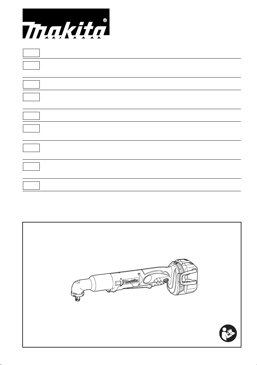
GB Cordless Angle Impact Wrench Instruction manual
F Outil d’entraînement à impact Manuel d’instructions
angulaire sans fil
D Akku-Winkelschlagschrauber Betriebsanleitung
I Avvitatrice angolare ad Istruzioni per l’uso
impulsi a batteria
NL Haakse accuslagdopsleutel Gebruiksaanwijzing
E Llave de impacto angular Manual de instrucciones
sin cables
P Chave de percussão para Manual de instruções
cantos sem fios
DK Ledningsfri Brugsanvisning
vinkelslagskruenøgle
GR Γωνιακό παλμικό κλειδί μπαταρίας Οδηγίες χρήσης
DTL062
DTL063
008503
1 012122 2 012128
1
2
3
4
5
6
7
8
A
B
9
10
11
3 015659 4 008330
5 008498 6 008331
12
7 008496 8 008338
2
14
13
15
16
12
18
19
50
40
30
20
10
0
01
2
3
M12
(M12)
M10
(M10)
M8
(M8)
(408)
(204)
(510)
(306)
(102)
21
23
20 22
17
9 008335 10 008336
11 002828 12 002829
13 008497 14 008500
3
40
(408)
30
(306)
24
M8
(M8)
20
20 22
(204)
10
(102)
0
M6
(M6)
0123
23
15 008499
4
ENGLISH (Original instructions)
Explanation of general view
1. Red indicator
2. Button
3. Battery cartridge
4. Star marking
5. Indicator lamps
6. Check button
7. Switch lever
8. Lamp
9. Reversing switch lever
10. Socket
11. An vil
12. Groove
13. Screw
14. Hook
15. Hex bolt
16. Angle head
17. Tooth
18. Straight head
19. Ratchet head
20. Standard bolt
21. Fastening torque
22. Proper fastening torque
23. Fastening time (S)
24. High tensile bolt
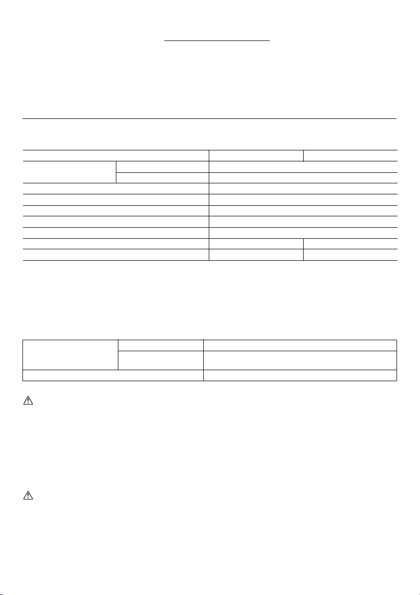
SPECIFICATIONS
Model DTL062 DTL063
Capacities
Square drive 9.5 mm
No load speed (min
Impacts per minute 0 - 3,000
Max. fastening torque 60 N•m
Overall length 387 mm
Net weight 1.4 - 1.8 kg 1.4 - 2.0 kg
Rated voltage D.C. 14.4 V D.C. 18 V
• Due to our continuing program of research and development, the specifications herein are subject to change without
notice.
• Specifications may differ from country to country.
• The weight may differ depending on the attachment(s), including the battery cartridge. The lightest and heaviest
combination, according to EPTA-Procedure 01/2014, are shown in the table.
Standard bolt M4 - M12
High tensile bolt M4 - M8
-1
) 0 - 2,000
Applicable battery cartridge and charger
Battery cartridge
Charger DC18RC/DC18RD/DC18RE/DC18SD/DC18SE/DC18SF
• Some of the battery cartridges and chargers listed above may not be available depending on your region of residence.
WARNING:
• Only use the battery cartridges and chargers listed above. Use of any other battery cartridges and chargers may
cause injury and/or fire.
Intended use
The tool is intended for screw driving in wood, metal and
plastic.
General power tool safety
warnings
WARNING: Read all safety warnings, instructions,
illustrations and specifications provided with this
power tool. Failure to follow all instructions listed below
may result in electric shock, fire and/or serious injury.
D.C.14.4 V Model BL1415N/BL1430/BL1430B/BL1440/BL1450/BL1460B
D.C.18 V Model
ENE033-1
BL1815N/BL1820/BL1820B/BL1830/BL1830B/BL1840/
BL1840B/BL1850/BL1850B/BL1860B
Save all warnings and
instructions for future reference.
The term “power tool” in the warnings refers to your
mains-operated (corded) power tool or battery-operated
GEA010-2
(cordless) power tool.
CORDLESS IMPACT WRENCH
SAFETY WARNINGS
1. Hold the power tool by insulated gripping
surfaces, when performing an operation where the
fastener may contact hidden wiring. Fasteners
contacting a “live” wire may make exposed metal parts
GEB138-1
5

of the power tool “live” and could give the operator an
electric shock.
2. Wear ear protectors.
3. Check the impact socket carefully for wear, cracks
or damage before installation.
4. Hold the tool firmly.
5. Keep hands away from rotating parts.
6. Always be sure you have a firm footing.
Be sure no one is below when using the tool in
high locations.
7. The proper fastening torque may differ depending
upon the kind or size of the bolt. Check the torque
with a torque wrench.
For preparation of the item being shipped, consulting
an expert for hazardous material is required. Please
also observe possibly more detailed national
regulations.
Tape or mask off open contacts and pack up the
battery in such a manner that it cannot move around in
the packaging.
11. Follow your local regulations relating to disposal
of battery.
12. Use the batteries only with the products specified
by Makita. Installing the batteries to non-compliant
products may result in a fire, excessive heat,
explosion, or leak of electrolyte.
SAVE THESE INSTRUCTIONS.
WARNING: DO NOT let comfort or familiarity with
product (gained from repeated use) replace strict
adherence to safety rules for the subject product.
MISUSE or failure to follow the safety rules stated in
this instruction manual may cause serious personal
injury.
IMPORTANT SAFETY
INSTRUCTIONS FOR BATTERY
CARTRIDGE
1. Before using battery cartridge, read all
instructions and cautionary markings on (1)
battery charger, (2) battery, and (3) product using
battery.
2. Do not disassemble battery cartridge.
3. If operating time has become excessively shorter,
stop operating immediately. It may result in a risk
of overheating, possible burns and even an
explosion.
4. If electrolyte gets into your eyes, rinse them out
with clear water and seek medical attention right
away. It may result in loss of your eyesight.
5. Do not short the battery cartridge:
(1) Do not touch the terminals with any
conductive material.
(2) Avoid storing battery cartridge in a container
with other metal objects such as nails, coins,
etc.
(3) Do not expose battery cartridge to water or
rain.
A battery short can cause a large current flow,
overheating, possible burns and even a
breakdown.
6. Do not store the tool and battery cartridge in
locations where the temperature may reach or
exceed 50°C (122°F).
7. Do not incinerate the battery cartridge even if it is
severely damaged or is completely worn out. The
battery cartridge can explode in a fire.
8. Be careful not to drop or strike battery.
9. Do not use a damaged battery.
10. The contained lithium-ion batteries are subject to
the Dangerous Goods Legislation requirements.
For commercial transports e.g. by third parties,
forwarding agents, special requirement on packaging
and labeling must be observed.
6
ENC007-12
SAVE THESE INSTRUCTIONS.
CAUTION: Only use genuine Makita batteries.
Use of non-genuine Makita batteries, or batteries that
have been altered, may result in the battery bursting
causing fires, personal injury and damage. It will also void
the Makita warranty for the Makita tool and charger.
Tips for maintaining maximum battery life
1. Charge the battery cartridge before completely
discharged.
Always stop tool operation and charge the battery
cartridge when you notice less tool power.
2. Never recharge a fully charged battery cartridge.
Overcharging shortens the battery service life.
3. Charge the battery cartridge with room
temperature at 10°C - 40°C (50°F - 104°F). Let a hot
battery cartridge cool down before charging it.
4. Charge the battery cartridge if you do not use it for
a long period (more than six months).
FUNCTIONAL DESCRIPTION
CAUTION:
• Always be sure that the tool is switched off and the
battery cartridge is removed before adjusting or
checking function on the tool.
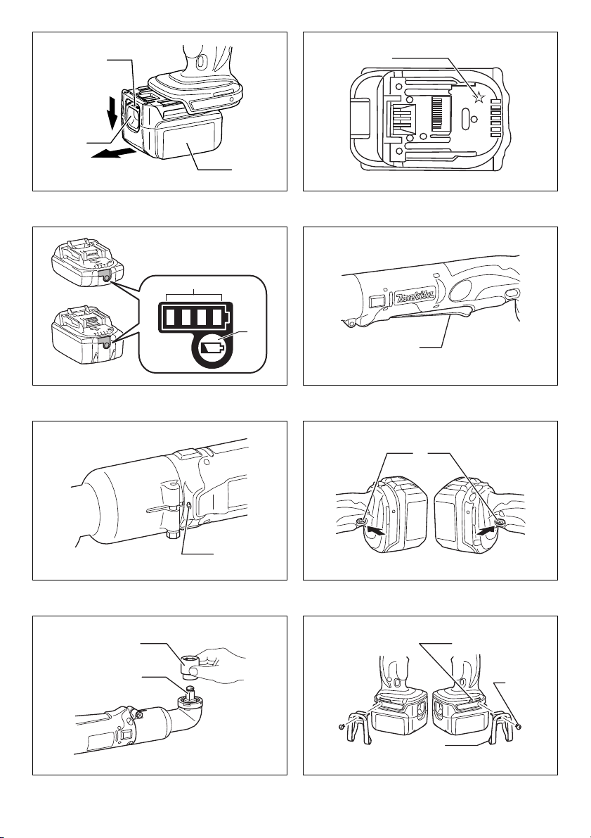
Installing or removing battery cartridge
(Fig. 1)
• Always switch off the tool before installing or removing
of the battery cartridge.
• To remove the battery cartridge, slide it from the tool
while sliding the button on the front of the cartridge.
• To install the battery cartridge, align the tongue on the
battery cartridge with the groove in the housing and slip
it into place. Always insert it all the way until it locks in
place with a little click. If you can see the red indicator
on the upper side of the button, it is not locked
completely. Install it fully until the red indicator cannot
be seen. If not, it may accidentally fall out of the tool,
causing injury to you or someone around you.
• Do not use force when installing the battery cartridge. If
the cartridge does not slide in easily, it is not being
inserted correctly.
Battery protection system (Lithium-ion
battery with star marking) (Fig. 2)
Lithium-ion batteries with a star marking are equipped
with a protection system. This system automatically cuts
off power to the tool to extend battery life.
The tool will automatically stop during operation if the tool
and/or battery are placed under one of the following
conditions:
• Overloaded:
The tool is operated in a manner that causes it to
draw an abnormally high current.
In this situation, release the trigger switch on the tool
and stop the application that caused the tool to
become overloaded. Then pull the trigger switch
again to restart.
If the tool does not start, the battery is overheated. In
this situation, let the battery cool before pulling the
trigger switch again.
• Low battery voltage:
The remaining battery capacity is too low and the tool
will not operate. In this situation, remove and
recharge the battery.
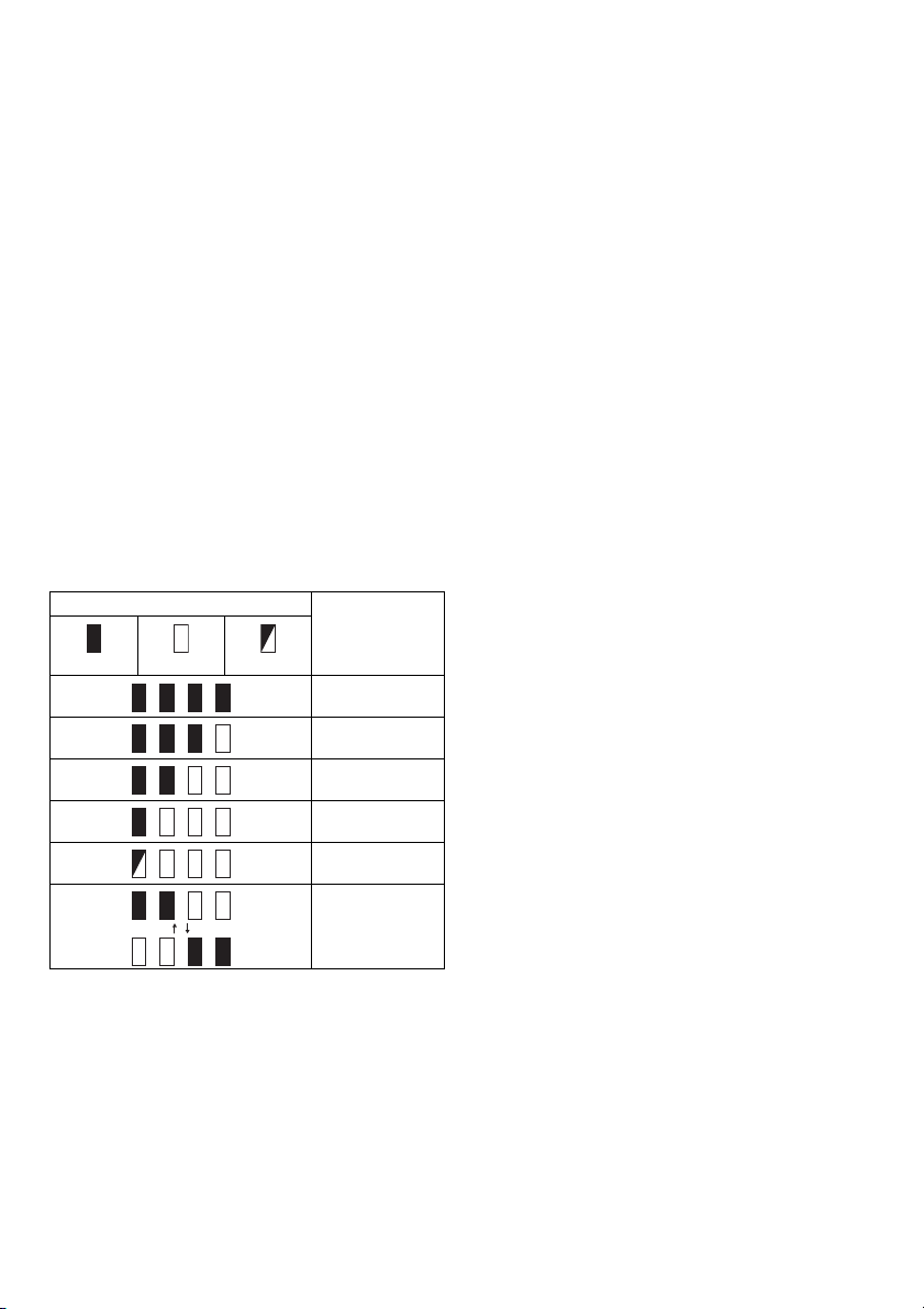
Indicating the remaining battery capacity
Only for battery cartridges with the indicator (Fig. 3)
Press the check button on the battery cartridge to indicate
the remaining battery capacity. The indicator lamps light
up for a few seconds.
Indicator lamps
Lighted Off Blinking
NOTE:
• Depending on the conditions of use and the ambient
temperature, the indication may differ slightly from the
actual capacity.
Remaining
capacity
75% to 100%
50% to 75%
25% to 50%
0% to 25%
Charge the
battery.
The battery may
have
malfunctioned.
Switch action
CAUTION:
• Before inserting the battery cartridge into the tool,
always check to see that the switch lever actuates
properly and returns to the “OFF” position when
released. (Fig. 4)
To start the tool, simply pull the switch lever. Tool speed is
increased by increasing pressure on the switch lever.
Release the switch lever to stop.
Lighting up the front lamp
CAUTION:
• Do not look in the light or see the source of light
directly. (Fig. 5)
Pull the switch lever to light up the lamp. The lamp keeps
on lighting while the switch lever is being pulled. The light
automatically goes out 10 - 15 seconds after the switch
lever is released.
NOTE:
• Use a dry cloth to wipe the dirt off the lens of lamp. Be
careful not to scratch the lens of lamp, or it may lower
the illumination.
Reversing switch action (Fig. 6)
This tool has a reversing switch to change the direction of
rotation. Depress the reversing switch lever from the A
side for clockwise rotation or from the B side for
counterclockwise rotation.
When the reversing switch lever is in the neutral position,
the switch lever cannot be pulled.
CAUTION:
• Always check the direction of rotation before operation.
• Use the reversing switch only after the tool comes to a
complete stop. Changing the direction of rotation
before the tool stops may damage the tool.
• When not operating the tool, always set the reversing
switch lever to the neutral position.
ASSEMBLY
CAUTION:
• Always be sure that the tool is switched off and the
battery cartridge is removed before carrying out any
work on the tool.
Selecting correct socket
Always use the correct size socket for bolts and nuts. An
incorrect size socket will result in inaccurate and
inconsistent fastening torque and/or damage to the bolt or
nut.
Installing or removing socket (Fig. 7)
To install the socket, push it onto the anvil of the tool until
it locks into place.
To remove the socket, simply pull it off.
Hook (Accessory)
CAUTION:
• When installing the hook, tighten the screw firmly.
Failure to do so may cause the breakage of the tool or
personal injury. (Fig. 8)
The hook is convenient for temporarily hanging the tool.
This can be installed on either side of the tool.
To install the hook, insert it into a groove in the tool
housing on either side and then secure it with a screw.
To remove, loosen the screw and then take it out.
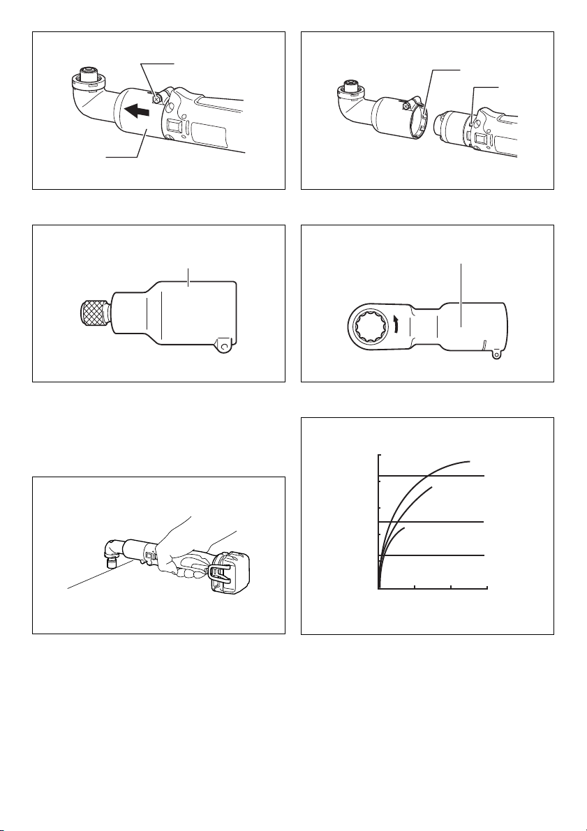
Adjusting the angle head
The angle head can be adjusted 360° (8 positions in 45degree increments). To adjust it, loosen the hex bolt and
remove the angle head.
7

Adjust the angle head to the desired position and reinstall
it so that the teeth on the housing will match up with the
grooves in the angle head. Then tighten the hex bolt to
secure the angle head. (Fig. 9 & 10)
Straight head and ratchet head
(Accessory)
Straight heads and ratchet heads are available as optional
accessories for various applications on the job. (Fig. 11 &
12)
OPERATION
CAUTION:
• Always insert the battery cartridge all the way until it
locks in place. If you can see the red part on the upper
side of the button, it is not locked completely.
Insert it fully until the red part cannot be seen. If not, it
may accidentally fall out of the tool, causing injury to
you or someone around you.
Hold the tool firmly and place the socket over the bolt or
nut. Turn the tool on and fasten for the proper fastening
time. (Fig. 13)
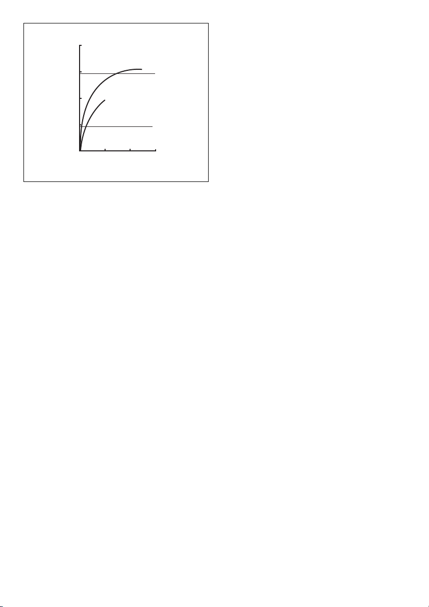
The proper fastening torque may differ depending upon
the kind or size of the bolt, the material of the workpiece to
be fastened, etc. The relation between fastening torque
and fastening time is shown in the figures. (Fig. 14 & 15)
NOTE:
• Hold the tool pointed straight at the bolt or nut.
• Excessive fastening torque may damage the bolt/nut or
socket. Before starting your job, always perform a test
operation to determine the proper fastening time for
your bolt or nut.
• If the tool is operated continuously until the battery
cartridge has discharged, allow the tool to rest for
15 minutes before proceeding with a fresh battery.
The fastening torque is affected by a wide variety of
factors including the following. After fastening, always
check the torque with a torque wrench.
1. When the battery cartridge is discharged almost
completely, voltage will drop and the fastening torque
will be reduced.
2. Driver bit or socket bit
• Failure to use the correct size driver bit or socket bit
will cause a reduction in the fastening torque.
• A worn socket (wear on the hex end or square end)
will cause a reduction in the fastening torque.
3. Bolt
• Even though the torque coefficient and the class of
bolt are the same, the proper fastening torque will
differ according to the diameter of bolt.
• Even though the diameters of bolts are the same,
the proper fastening torque will differ according to
the torque coefficient, the class of bolt and the bolt
length.
4. The use of the universal joint or the extension bar
somewhat reduces the fastening force of the impact
wrench. Compensate by fastening for a longer period
of time.
5. The manner of holding the tool or the material of
driving position to be fastened will affect the torque.
6. Operating the tool at low speed will cause a reduction
in the fastening torque.
MAINTENANCE
CAUTION:
• Always be sure that the tool is switched off and the
battery cartridge is removed before attempting to
perform inspection or maintenance.
• Never use gasoline, benzine, thinner, alcohol or the
like. Discoloration, deformation or cracks may result.
To maintain product SAFETY and RELIABILITY, repairs,
any other maintenance or adjustment should be
performed by Makita Authorized Service Centers, always
using Makita replacement parts.
OPTIONAL ACCESSORIES
CAUTION:
• These accessories or attachments are recommended
for use with your Makita tool specified in this manual.
The use of any other accessories or attachments might
present a risk of injury to persons. Only use accessory
or attachment for its stated purpose.
If you need any assistance for more details regarding
these accessories, ask your local Makita Service Center.
• Sockets
• Extension bar
• Universal joint
• Bit adapter
• Various type of Makita genuine batteries and chargers
NOTE:
• Some items in the list may be included in the tool
package as standard accessories. They may differ from
country to country.
Noise
The typical A-weighted noise level determined according
to EN62841:
Sound pressure level (L
Sound power level (L
Uncertainty (K): 3 dB (A)
• The declared noise emission value(s) has been
measured in accordance with a standard test method
and may be used for comparing one tool with another.
• The declared noise emission value(s) may also be
used in a preliminary assessment of exposure.
WARNING:
• Wear ear protection.
• The noise emission during actual use of the power
tool can differ from the declared value(s)
depending on the ways in which the tool is used
especially what kind of workpiece is processed.
• Be sure to identify safety measures to protect the
operator that are based on an estimation of
exposure in the actual conditions of use (taking
account of all parts of the operating cycle such as
the times when the tool is switched off and when it
is running idle in addition to the trigger time).
): 88 dB (A)
pA
): 99 dB (A)
WA
ENG905-1
ENG907-1
8

Vibration
ENG900-1
The vibration total value (tri-axial vector sum) determined
according to EN62841:
Model DTL062
Work mode: impact tightening of fasteners of the
maximum capacity of the tool
Vibration emission (a
Uncertainty (K): 2.0 m/s
): 14.5 m/s
h
2
2
Model DTL063
Work mode: impact tightening of fasteners of the
maximum capacity of the tool
Vibration emission (a
Uncertainty (K): 2.0 m/s
): 16.5 m/s
h
2
2
ENG901-2
• The declared vibration total value(s) has been
measured in accordance with a standard test method
and may be used for comparing one tool with another.
• The declared vibration total value(s) may also be used
in a preliminary assessment of exposure.
WARNING:
• The vibration emission during actual use of the
power tool can differ from the declared value(s)
depending on the ways in which the tool is used
especially what kind of workpiece is processed.
• Be sure to identify safety measures to protect the
operator that are based on an estimation of
exposure in the actual conditions of use (taking
account of all parts of the operating cycle such as
the times when the tool is switched off and when it
is running idle in addition to the trigger time).
EC Declaration of Conformity
For European countries only
The EC declaration of conformity is included as Annex A
to this instruction manual.
9

FRANÇAIS (Instructions d’origine)
Descriptif
1. Voyant rouge
2. Bouton
3. Batterie
4. Étoile
5. Voyants
6. Bouton de vérification
7. Levier de l’interrupteur
8. Lampe
9. Levier de l’inverseur
10. Embout
11. En clu me
12. Rainure
13. Vis
14. Crochet
15. Boulon hexagonal
16. Tête d’angle
17. Dent
18. Tête droite
19. Tête de rochet
20. Boulon hexagonal
21. Couple de serrage
22. Couple de serrage approprié
23. Délai de fixation (S)
24. Boulon à haute résistance à la
traction
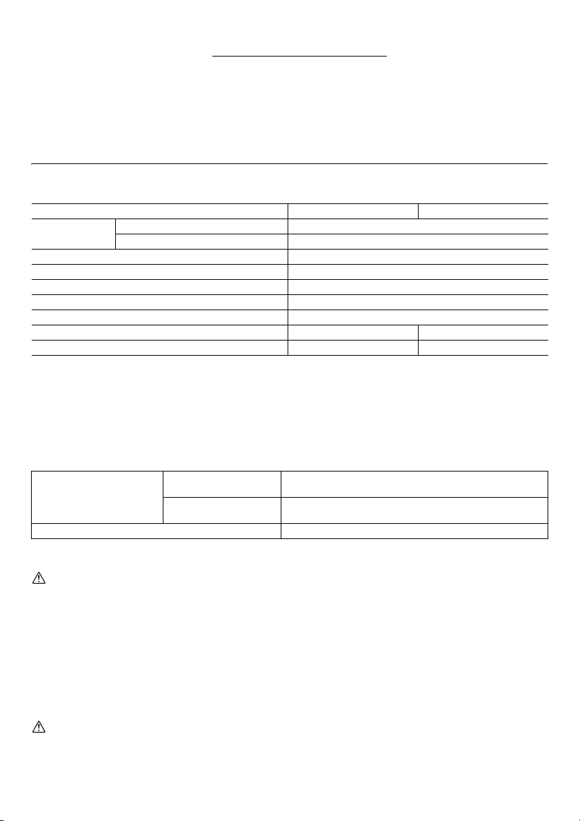
SPÉCIFICATIONS
Modèle DTL062 DTL063
Capacités
• Étant donné l’évolution constante de notre programme de recherche et de développement, les spécifications
contenues dans ce manuel sont sujettes à des modifications sans préavis.
• Les spécifications peuvent varier suivant les pays.
• Le poids peut varier en fonction des pièces complémentaires, notamment de la batterie. La combinaison la plus légère
et la combinaison la plus lourde, selon la procédure EPTA du 01/2014, sont présentées dans le tableau.
Boulon à haute résistance à la traction M4 - M8
Carré conducteur 9,5 mm
Vitesse à vide (min
Impacts par minute 0 - 3 000
Couple de serrage maxi. 60 N•m
Tension nominale 14,4 V C.C. 18 V C.C.
Boulon hexagonal M4 - M12
-1
) 0 - 2 000
Longueur totale 387 mm
Poids net 1,4 - 1,8 kg 1,4 - 2,0 kg
Batterie standard et chargeur applicables
Batterie
Chargeur DC18RC/DC18RD/DC18RE/DC18SD/DC18SE/DC18SF
• Certains types de batterie et de chargeurs répertoriés ci-dessus peuvent ne pas être disponibles en fonction de votre
région ou lieu de résidence.
AVERTISSEMENT:
• Utilisez uniquement les batteries et chargeurs indiqués ci-dessus. L'utilisation de toute autre batterie ou d'un autre
chargeur peut provoquer des blessures et/ou déclencher un incendie.
Utilisations
L’outil est conçu pour le vissage dans le bois, le métal et
le plastique.
C.C. 14,4 V Modèle BL1415N/BL1430/BL1430B/BL1440/BL1450/BL1460B
C.C. 18 V Modèle
ENE033-1
BL1815N/BL1820/BL1820B/BL1830/BL1830B/BL1840/
BL1840B/BL1850/BL1850B/BL1860B
Conservez toutes les mises en
garde et instructions pour
référence ultérieure.
Consignes de sécurité générales
pour outils électriques
AVERTISSEMENT : Veuillez lire les consignes de
sécurité, instructions, illustrations et spécifications
qui accompagnent cet outil électrique. Le non-respect
de toutes les instructions indiquées ci-dessous peut
entraîner une électrocution, un incendie et/ou de graves
blessures.
10
GEA010-2
Le terme « outil électrique » dans les avertissements fait
référence à l’outil électrique alimenté par le secteur (avec
cordon d’alimentation) ou à l’outil électrique fonctionnant
sur batterie (sans cordon d’alimentation).

CONSIGNES DE SÉCURITÉ POUR
BOULONNEUSE SANS FIL
1. Tenez l’outil électrique par des surfaces de prise
isolées lorsque vous effectuez une tâche au cours
de laquelle la vis ou le boulon peut entrer en
contact avec des fils cachés. Le contact de la vis ou
du boulon avec un fil sous tension peut transmettre du
courant dans les pièces métalliques exposées de
l’outil et électrocuter l’opérateur.
2. Portez un casque anti-bruit.
3. Vérifiez que la douille à choc n’est pas usée,
fissurée ou endommagée avant l’installation.
4. Tenez votre outil fermement.
5. Gardez les mains éloignées des pièces en
rotation.
6. Ayez toujours une assise ferme sous vos pieds.
Veillez à ce que personne ne se trouve en dessous
de vous quand vous utilisez l’outil en hauteur.
7. Le couple de serrage correct peut varier en
fonction du type ou de la dimension du boulon.
Vérifiez le couple à l’aide d’une clé
dynamométrique.
GEB138-1
CONSERVEZ CES
INSTRUCTIONS.
AVERTISSEMENT : NE vous laissez PAS tromper
(au fil d’une utilisation répétée) par un sentiment
d’aisance et de familiarité avec le produit, en
négligeant le respect rigoureux des consignes de
sécurité qui accompagnent le produit en question.
La MAUVAISE UTILISATION de l’outil ou l’ignorance
des consignes de sécurité indiquées dans ce mode
d’emploi peut entraîner de graves blessures.
Un court-circuit de la batterie risque de provoquer
un fort courant, une surchauffe, parfois des
brûlures et même une panne.
6. Ne rangez pas l’outil ou la batterie dans des
endroits où la température risque d’atteindre ou
de dépasser 50 °C (122 °F).
7. Ne jetez pas la batterie au feu même si elle est
sérieusement endommagée ou complètement
épuisée. La batterie peut exploser au contact du
feu.
8. Veillez à ne pas laisser tomber ou heurter la
batterie.
9. N’utilisez pas de batterie endommagée.
10. Les batteries au lithium-ion contenues sont
soumises aux exigences de la législation sur les
marchandises dangereuses.
Lors du transport commercial par des tierces parties
ou des transitaires par exemple, des exigences
spécifiques en matière d’étiquetage et d’emballage
doivent être respectées.
Pour la préparation de l’article expédié, il est
nécessaire de consulter un expert en matériau
dangereux. Veuillez également respecter les
réglementations nationales susceptibles d’être plus
détaillées.
Recouvrez les contacts exposés avec du ruban
adhésif ou du ruban de masquage et emballez la
batterie de telle sorte qu’elle ne puisse pas bouger
dans l’emballage.
11. Respectez les réglementations locales relatives à
la mise au rebut des batteries.
12. Utilisez les batteries uniquement avec les produits
spécifiés par Makita. L’installation des batteries sur
des produits non conformes peut entraîner un
incendie, une chaleur excessive, une explosion ou
une fuite d’électrolyte.
CONSIGNES DE SECURITE
IMPORTANTES POUR LA
BATTERIE
ENC007-12
1. Avant d’utiliser la batterie, veuillez lire toutes les
instructions et tous les avertissements inscrits
sur (1) le chargeur, (2) la batterie et (3) l’appareil
alimenté par la batterie.
2. Ne démontez pas la batterie.
3. Cessez immédiatement d’utiliser l’outil si le temps
de fonctionnement devient excessivement court. Il
y a risque de surchauffe, de brûlures, voire
d’explosion.
4. Si l’électrolyte pénètre dans vos yeux, rincez-les à
l’eau claire et consultez immédiatement un
médecin. Il y a risque de perte de la vue.
5. Évitez de court-circuiter la batterie :
(1) Ne touchez les bornes avec aucun matériau
conducteur.
(2) Évitez de ranger la batterie dans un
contenant où se trouvent d’autres objets
métalliques tels que des clous, pièces de
monnaie, etc.
(3) N’exposez pas la batterie à l’eau ou à la pluie.
CONSERVEZ CES
INSTRUCTIONS.
ATTENTION : N’utilisez que des batteries Makita
d’origine.
L’utilisation de batteries de marque autre que Makita ou
de batteries modifiées peut provoquer l’explosion des
batteries, ce qui présente un risque d’incendie, de
dommages matériels et corporels. Cela annulera
également la garantie Makita pour l’outil et le chargeur
Makita.
Conseils pour assurer la durée de vie
optimale de la batterie
1. Rechargez la batterie avant qu’elle ne soit
complètement épuisée.
Arrêtez toujours l’outil et rechargez la batterie
quand vous constatez que la puissance de l’outil
diminue.
2. Ne rechargez jamais une batterie complètement
chargée.
La surcharge réduit la durée de service de la
batterie.
3. Chargez la batterie alors que la température de la
pièce se trouve entre 10 °C et 40 °C (50 °F et
11
104 °F). Si une batterie est chaude, laissez-la
refroidir avant de la charger.
4. Chargez la batterie si vous ne l’avez pas utilisée
pendant une longue période (plus de six mois).
DESCRIPTION DU
FONCTIONNEMENT
ATT EN TIO N :
• Veillez toujours à éteindre l’outil et déposer la batterie
avant de régler ou vérifier le fonctionnement de
l’appareil.
Installation et retrait de la batterie (Fig. 1)
• Éteignez toujours l’outil avant d’installer ou de déposer
la batterie.
• Pour retirer la batterie, faites glisser le bouton à l’avant
de la batterie et sortez la batterie.
• Pour installer la batterie, alignez sa languette sur la
rainure qui se trouve à l’intérieur du carter, puis glissez
la batterie pour la mettre en place. Insérez-la toujours
bien à fond, jusqu’à ce qu’elle se verrouille en émettant
un léger clic. Si vous pouvez voir le voyant rouge sur la
face supérieure du bouton, la batterie n’est pas
parfaitement verrouillée. Installez-la à fond, jusqu’à ce
que le voyant rouge ne soit plus visible. Sinon, elle
risque de tomber accidentellement de l’outil, en vous
blessant ou en blessant une personne située près de
vous.
• N’appliquez pas une force excessive lors de
l’installation de la batterie. Si la batterie ne glisse pas
aisément, c’est qu’elle n’est pas insérée correctement.
Système de protection de la batterie
(batterie au lithium-ion comportant une
étoile) (Fig. 2)
Les batteries au lithium-ion comportant une étoile sont
équipées d’un système de protection. Ce système coupe
automatiquement l’alimentation en électricité vers l’outil
afin de prolonger sa durée de vie.
L’outil s’arrête automatiquement pendant l’utilisation
lorsqu’il et/ou la batterie se trouvent dans l’une des
situations suivantes :
• Surchargé :
L’outil fonctionne de manière à créer un courant
anormalement élevé.
Dans ce cas, relâchez la gâchette située sur l’outil et
arrêtez l’application ayant provoqué la surcharge de
l’outil. Ensuite, tirez à nouveau sur la gâchette pour
redémarrer l’outil.
Si l’outil ne démarre pas, la batterie est en
surchauffe. Dans ce cas, laissez la batterie refroidir
avant de tirer à nouveau sur la gâchette.
• Basse tension :
L’autonomie restante est trop basse et l’outil ne
fonctionnera pas. Dans ce cas, retirez la batterie et
rechargez-la.
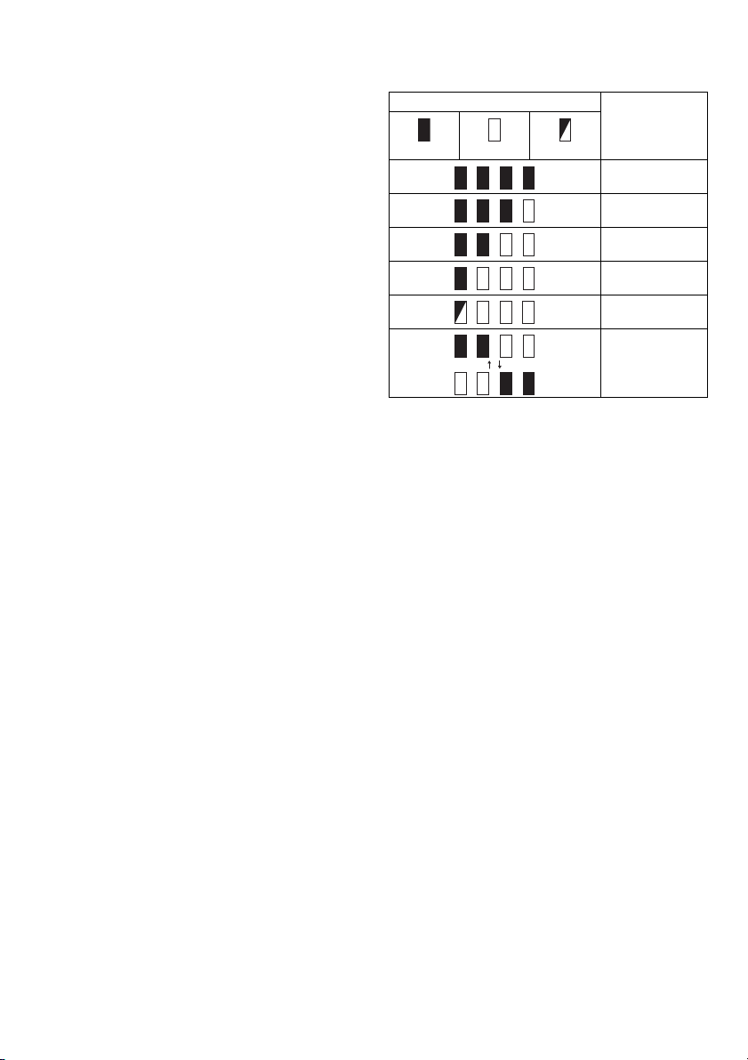
Indication de l’autonomie restante de la
batterie
Uniquement pour les batteries avec voyant lumineux
(Fig. 3)
Appuyez sur le bouton de vérification sur la batterie pour
indiquer la charge restante de la batterie. Les témoins
s’allument pendant quelques secondes.
Voyants
Allumé Éteint Clignotant
REMARQUE :
• Selon les conditions d’utilisation et la température
ambiante, les indications peuvent différer légèrement
de l’autonomie réelle restante.
Autonomie
restante
75 % à 100 %
50 % à 75 %
25 % à 50 %
0% à 25%
Recharger la
batterie.
Il est possible que
la batterie ait mal
fonctionné.
Interrupteur
ATT EN TIO N :
• Avant d’insérer la batterie dans l’outil, vérifiez toujours
que la gâchette fonctionne bien et revient en position
d’arrêt lorsque libérée. (Fig. 4)
Pour mettre l’outil en marche, tirez simplement sur le
levier de l’interrupteur. La vitesse de l’outil augmente à
mesure que l’on accroît la pression sur le levier de
l’interrupteur. Pour arrêter l’outil, relâchez le levier de
l’interrupteur.
Allumage des lampes
ATT EN TIO N :
• Ne regardez pas directement la lumière ou la source
de lumière. (Fig. 5)
Appuyez sur la gâchette pour allumer la lampe. La lampe
demeure allumée tant que la pression sur la gâchette est
maintenue. La lumière s’éteint d’elle-même de 10 à
15 secondes après la libération de la gâchette.
REMARQUE :
• Utilisez un chiffon sec pour essuyer les saletés qui
recouvrent la lentille de la lampe. Prenez garde de
rayer la lentille de la lampe, sinon sa capacité
d’éclairage sera affectée.
Marche arrière (Fig. 6)
L’outil possède un inverseur qui permet de changer le
sens de rotation. Appuyez sur le levier de l’inverseur par
le côté A pour une rotation dans le sens des aiguilles
d’une montre, ou par le côté B pour une rotation en sens
inverse.
La pression sur la gâchette n’est pas possible lorsque le
levier de l’inverseur se trouve en position neutre.
12

ATT EN TIO N :
• Vérifiez toujours le sens de rotation avant de mettre
l’outil en marche.
• N’actionnez l’inverseur qu’une fois l’outil complètement
arrêté. Si vous changez le sens de rotation de l’outil
avant l’arrêt de l’outil, vous risquez de l’endommager.
• Lorsque vous n’utilisez pas l’outil, placez toujours le
levier de l’inverseur en position neutre.
ASSEMBLAGE
ATT EN TIO N :
• Assurez-vous toujours que l’outil est hors tension et
que la batterie est retirée avant d’effectuer toute
intervention sur l’outil.
Choisissez un embout approprié
Toujours choisir la taille de l’embout correct pour les
boulons et les écrous. Un embout de taille incorrect
résultera en un couple de serrage inconsistant et imprécis
et/ou endommagera le boulon ou l’écrou.
Installation ou dépose de la batterie
(Fig. 7)
Pour installer l’embout, pousser le dans l’enclume de
l’outil jusqu’à ce qu’il se verrouille en place.
Pour retirer l’embout, tirez le simplement.
Crochet (Accessoire)
ATT EN TIO N :
• Quand vous installez le crochet, serrez la vis
fermement. Ne pas le faire risque de casser l’outil ou
causer des blessures personnelles. (Fig. 8)
L’outil est équipé d’un crochet pratique qui permet de le
suspendre temporairement.
Il s’installe d’un côté comme de l’autre de l’outil.
Pour installer le crochet, insérez-le dans une rainure du
carter de l’outil d’un côté ou de l’autre puis serrez-le avec
une vis.
Pour le retirer, desserrez la vis et enlevez-le.
Réglage de la tête d’angle
La tête d’angle peut être ajustée à 360° (8 positions en
des incréments à 45 degrés). Pour la régler, desserrez le
boulon hexagonal et retirez la tête d’angle.
Réglez la tête d’angle à la position désirée et réinstallez-la
de sorte que les dents dans le carter correspondront avec
les rainures de la tête d’angle. Serrez ensuite le boulon
hexagonal dans le sens des aiguilles d’une montre pour
immobiliser le couvercle central. (Fig. 9 et 10)
Tête droite et tête de rochet (Accessoire)
Les têtes droites et les têtes de rochets sont disponibles
comme accessoires optionnels pour diverses utilisations
sur le poste. (Fig. 11 et 12)
UTILISATION
ATT EN TIO N :
• Insérez toujours la batterie bien à fond, jusqu’à ce
qu’elle se verrouille en place. Si vous pouvez voir la
partie rouge sur la face supérieure du bouton, la
batterie n’est pas parfaitement verrouillée.
Insérez-la à fond, jusqu’à ce que la partie rouge ne soit
plus visible. Dans le cas contraire, la batterie risque de
tomber accidentellement de l’outil et de vous blesser
ou de blesser une personne se trouvant près de vous.
Tenir l’outil fermement et placez l’embout au-dessus du
boulon ou de la vis. Allumez l’outil et attachez-le pour le
délai de fixation correct. (Fig. 13)
Le couple de serrage correct peut différer selon le type ou
la taille du boulon, le matériel de la pièce de travail à fixer,
etc. La relation entre le couple de serrage et le délai de
fixation est illustré aux figures. (Fig. 14 et 15)
REMARQUE :
• Tenez l’outil pointé droit sur le boulon ou l’écrou.
• Un couple de serrage excessif peut endommager le
boulon/écrou ou l’embout. Avant de commencer votre
travail, effectuez toujours une opération d’essai pour
déterminer le délai de fixation approprié pour votre vis.
• Si l’outil a fonctionné de façon continue jusqu’à ce que
la batterie s’épuise, laissez-le reposer pendant
15 minutes avant de poursuivre avec une batterie
fraîche.
Le couple de serrage est affecté par une grande variété
de facteurs, notamment ce qui suit. Après le serrage,
vérifiez toujours le couple à l’aide d’une clé
dynamométrique.
1. Quand la batterie est presque totalement déchargée,
la tension chutera et le couple de serrage sera réduit.
2. Embout ou embout à douille
• Si vous n’utilisez pas un embout ou un embout à
douille de taille appropriée, cela entraînera une
diminution du couple de serrage.
• Un embout usé (l’usure est sur l’extrémité
hexagonale ou carrée) causera une réduction dans
le couple de serrage.
3. Boulon
• Bien que le coefficient de couple et la classe de
boulon soient identiques, le couple de serrage
approprié différera en fonction du diamètre du
boulon.
• Bien que les diamètres des boulons soient
identiques, le couple de serrage approprié différera
en fonction du coefficient de couple et de la classe
et de la longueur du boulon.
4. L’utilisation du joint universel ou de la barre
d’extension réduit quelque peu la force de serrage de
la clé à chocs. Compensez en serrant pendant plus
longtemps.
5. La manière de tenir l’outil ou le matériau de la position
d’entraînement à fixer affectera le couple.
6. L’opération de l’outil à une vitesse lente entraînera
une réduction du couple de serrage.
MAINTENANCE
ATT EN TIO N :
• Assurez-vous toujours que l’outil est hors tension et
que la batterie est retirée avant d’y effectuer tout travail
d’inspection ou d’entretien.
• N’utilisez jamais d’essence, de benzine, de diluant,
d’alcool ou de produit similaire. Ces produits risquent
de provoquer des décolorations, des déformations ou
des fissures.
Pour assurer la SÉCURITÉ et la FIABILITÉ du produit,
toute réparation et tout travail d’entretien ou de réglage
13

doivent être effectués par un Centre de service aprèsvente agréé Makita, avec des pièces de rechange Makita.
ACCESSOIRES FOURNIS EN
OPTION
ATTENTION :
• Ces accessoires ou pièces complémentaires sont
recommandés pour être utilisés avec l’outil Makita
spécifié dans ce mode d’emploi. L’utilisation de tout
autre accessoire ou pièce complémentaire peut
comporter un risque de blessure. N’utilisez les
accessoires ou pièces qu’aux fins auxquelles ils ont été
conçus.
Pour obtenir plus de détails sur ces accessoires,
contactez votre Centre de service local Makita.
• Embouts
• Barre d’extension
• Joint universel
• Partie d’embout
• Divers types de batteries et chargeurs de marque
Makita.
REMARQUE :
• Certains éléments de la liste peuvent être inclus en tant
qu’accessoires standard dans le coffret de l’outil
envoyé. Ils peuvent varier suivant les pays.
Bruit
Les niveaux de bruit pondéré A typiques ont été mesurés
selon la norme EN62841 :
Niveau de pression sonore (L
Niveau de puissance sonore (L
Incertitude (K) : 3 dB (A)
): 88dB (A)
pA
) : 99 dB (A)
WA
• La ou les valeurs d’émission de bruit déclarées ont été
mesurées conformément à la méthode de test
standard et peuvent être utilisées pour comparer les
outils entre eux.
• La ou les valeurs d’émission de bruit déclarées
peuvent aussi être utilisées pour l’évaluation
préliminaire de l’exposition.
AVERTISSEMENT :
• Portez un serre-tête antibruit.
• L’émission de bruit lors de l’usage réel de l’outil
électrique peut être différente de la ou des valeurs
déclarées, suivant la façon dont l’outil est utilisé,
particulièrement selon le type de pièce usinée.
• Les mesures de sécurité à prendre pour protéger
l’utilisateur doivent être basées sur une estimation
de l’exposition dans des conditions réelles
d’utilisation (en tenant compte de toutes les
composantes du cycle d’utilisation, comme par
exemple le moment de sa mise hors tension,
lorsqu’il tourne à vide et le moment de son
déclenchement).
ENG905-1
ENG907-1
Vibrations
ENG900-1
La valeur totale de vibration (somme du vecteur triaxial) a
été déterminée selon la norme EN62841 :
Modèle DTL062
Mode de fonctionnement : serrage avec chocs de
boulons ou d’écrous à la capacité maximale de l’outil
Émission des vibrations (a
Incertitude (K) : 2,0 m/s
): 14,5m/s
h
2
2
Modèle DTL063
Mode de fonctionnement : serrage avec chocs de
boulons ou d’écrous à la capacité maximale de l’outil
Émission des vibrations (a
Incertitude (K) : 2,0 m/s
): 16,5m/s
h
2
2
ENG901-2
• La ou les valeurs de vibration totales déclarées ont été
mesurées conformément à la méthode de test
standard et peuvent être utilisées pour comparer les
outils entre eux.
• La ou les valeurs de vibration totales déclarées
peuvent aussi être utilisées pour l’évaluation
préliminaire de l’exposition.
AVERTISSEMENT :
• L’émission de vibrations lors de l’usage réel de
l’outil électrique peut être différente de la ou des
valeurs déclarées, suivant la façon dont l’outil est
utilisé, particulièrement selon le type de pièce
usinée.
• Les mesures de sécurité à prendre pour protéger
l’utilisateur doivent être basées sur une estimation
de l’exposition dans des conditions réelles
d’utilisation (en tenant compte de toutes les
composantes du cycle d’utilisation, comme par
exemple le moment de sa mise hors tension,
lorsqu’il tourne à vide et le moment de son
déclenchement).
Déclaration de conformité CE
Pour les pays d’Europe uniquement
La Déclaration de conformité CE figure en Annexe A du
présent mode d’emploi.
14
DEUTSCH (Originalanweisungen)
Erklärung der Gesamtdarstellung
1. Roter Bereich
2. Taste
3. Akkublock
4. Sternmarkierung
5. Anzeigenlampen
6. Akkuprüftaste
7. Hebelschalter
8. Lampe
9. Umschalthebel
10. Steckeinsatz
11. Aufsatzhalter
12. Rille
13. Schraube
14. Einhängeclip
15. Sechskantschraube
16. Winkelkopf
17. Zahn
18. Gerader Kopf
19. Ratschenkopf
20. Standardbolzen
21. Anzugsmoment
22. Richtiges Anzugsmoment
23. Anzugszeit (s)
24. Höherfester Bolzen
TECHNISCHE ANGABEN
Modell DTL062 DTL063
Leistungen
Leerlaufdrehzahl (U/min
Schläge pro Minute 0 - 3.000
Max. Anzugsmoment 60 Nm
• Aufgrund unserer beständigen Forschungen und Weiterentwicklungen sind Änderungen an den hier angegebenen
Technischen Daten ohne Vorankündigung vorbehalten.
• Die Technischen Daten können in den einzelnen Ländern voneinander abweichen.
• Das Gewicht kann sich je nach Umfang und Art der vorhandenen Zubehörteile inkl. Akkublock ändern. Das Gewicht
der leichtest- und schwerstmöglichen Kombination, das im Einklang mit dem EPTA-Verfahren 01/2014 ermittelt wurde,
ist in der Tabelle aufgeführt.
Standardbolzen M4 - M12
Bolzen mit hohem Abschermoment M4 - M8
Vierkantaufsatz 9,5 mm
Gesamtlänge 387 mm
Nettogewicht 1,4 - 1,8 kg 1,4 - 2,0 kg
Nennspannung 14,4 V Gleichspannung 18 V Gleichspannung
-1
) 0 - 2.000
Zu verwendender Akkublock mit Ladegerät
14,4 V Gleichspannung
Akkublock
Ladegerät DC18RC/DC18RD/DC18RE/DC18SD/DC18SE/DC18SF
• In Abhängigkeit der Region, in der Sie ansässig sind, kann es vorkommen, dass einige von den oben aufgeführten
Akkublöcken und Ladegeräten nicht verfügbar sind.
WARNUNG:
• Verwenden Sie ausschließlich die oben angegebenen Akkublöcke und Ladegeräte. Bei Verwendung anderer
Akkublöcke und Ladegeräte besteht Verletzungs- und Brandgefahr.
Verwendungszweck
Das Werkzeug wurde für das Schrauben in Holz, Metall
und Kunststoff entwickelt.
Modell
18 V Gleichspannung
Modell
ENE033-1
Allgemeine
Sicherheitswarnungen für
Elektrowerkzeuge
WARNUNG: Lesen Sie alle mit diesem
Elektrowerkzeug gelieferten Sicherheitswarnungen,
Anweisungen, Abbildungen und technischen Daten
durch. Eine Missachtung der unten aufgeführten
GEA010-2
BL1415N/BL1430/BL1430B/BL1440/BL1450/BL1460B
BL1815N/BL1820/BL1820B/BL1830/BL1830B/BL1840/
BL1840B/BL1850/BL1850B/BL1860B
Anweisungen kann zu einem elektrischen Schlag, Brand
und/oder schweren Verletzungen führen.
Bewahren Sie alle Warnungen und
Anweisungen für spätere
Bezugnahme auf.
Der Ausdruck „Elektrowerkzeug“ in den Warnhinweisen
bezieht sich auf Ihr mit Netzstrom (mit Kabel) oder Akku
(ohne Kabel) betriebenes Elektrowerkzeug.
15

SICHERHEITSWARNUNGEN FÜR
AKKU-SCHLAGSCHRAUBER
GEB138-1
1. Halten Sie das Elektrowerkzeug nur an den
isolierten Griffflächen, wenn Sie Arbeiten
ausführen, bei denen die Gefahr besteht, dass das
Befestigungselement verborgene Kabel
kontaktiert. Bei Kontakt mit einem Strom führenden
Kabel können die freiliegenden Metallteile des
Elektrowerkzeugs ebenfalls Strom führend werden, so
dass der Benutzer einen elektrischen Schlag erleiden
kann.
2. Tragen Sie Gehörschützer.
3. Überprüfen Sie den Schlagsteckschlüsseleinsatz
vor der Montage sorgfältig auf Verschleiß, Risse
oder Beschädigung.
4. Halten Sie das Werkzeug mit festem Griff.
5. Halten Sie Ihre Hände von rotierenden Teilen fern.
6. Achten Sie stets auf sicheren Stand.
Vergewissern Sie sich bei Einsatz des Werkzeugs
an hochgelegenen Arbeitsplätzen, dass sich keine
Personen darunter aufhalten.
7. Das korrekte Anzugsmoment kann je nach Art
oder Größe der Schraube unterschiedlich sein.
Überprüfen Sie das Anzugsmoment mit einem
Drehmomentschlüssel.
DIESE ANWEISUNGEN
AUFBEWAHREN.
WARNUNG: Lassen Sie sich NICHT durch
Bequemlichkeit oder Vertrautheit mit dem Produkt
(durch wiederholten Gebrauch erworben) von der
strikten Einhaltung der Sicherheitsregeln für das
vorliegende Produkt abhalten.
MISSBRAUCH oder Missachtung der
Sicherheitsvorschriften in dieser Anleitung können
schwere Verletzungen verursachen.
WICHTIGE
SICHERHEITSANWEISUNGEN
FÜR AKKU
1. Lesen Sie vor der Verwendung des Akkublocks
alle Anweisungen und Sicherheitshinweise für das
Akkuladegerät (1), den Akku (2) und das Produkt
(3), für das der Akku verwendet wird, sorgfältig
durch.
2. Der Akkublock darf nicht zerlegt werden.
3. Falls die Betriebsdauer erheblich kürzer wird,
beenden Sie den Betrieb umgehend. Andernfalls
besteht die Gefahr einer Überhitzung sowie das
Risiko möglicher Verbrennungen und sogar einer
Explosion.
4. Wenn Elektrolyt in Ihre Augen gerät, waschen Sie
diese mit klarem Wasser aus und suchen Sie
sofort einen Arzt auf. Andernfalls können Sie Ihre
Sehfähigkeit verlieren.
5. Vermeiden Sie einen Kurzschluss des
Akkublocks:
(1) Die Kontakte dürfen nicht mit leitendem
Material in Berührung kommen.
16
ENC007-12
(2) Der Akkublock darf nicht in einem Behälter
aufbewahrt werden, in dem sich andere
metallische Gegenstände wie beispielsweise
Nägel, Münzen usw. befinden.
(3) Der Akkublock darf weder Feuchtigkeit noch
Regen ausgesetzt werden.
Ein Kurzschluss des Akkus kann zu hohem
Kriechstrom, Überhitzung, möglichen
Verbrennungen und sogar zu einer Zerstörung des
Werkzeugs führen.
6. Werkzeug und Akkublock dürfen nicht an Orten
aufbewahrt werden, an denen Temperaturen von
50°C oder darüber erreicht werden können.
7. Beschädigte oder verbrauchte Akkus dürfen nicht
verbrannt werden. Der Akkublock kann in den
Flammen explodieren.
8. Lassen Sie den Akku nicht fallen und vermeiden
Sie Schläge gegen den Akku.
9. Verwenden Sie niemals einen beschädigten Akku.
10. Die enthaltenen Lithium-Ionen-Akkus unterliegen
den Anforderungen der GefahrengutGesetzgebung.
Für kommerzielle Transporte, z. B. durch Dritte oder
Spediteure, müssen besondere Anforderungen zu
Verpackung und Etikettierung beachtet werden.
Zur Vorbereitung des zu transportierenden Artikels ist
eine Beratung durch einen Experten für Gefahrengut
erforderlich. Bitte beachten Sie möglicherweise
ausführlichere nationale Vorschriften.
Überkleben oder verdecken Sie offene Kontakte, und
verpacken Sie den Akku so, dass er sich in der
Verpackung nicht umher bewegen kann.
11. Befolgen Sie die in Ihrem Land geltenden
Bestimmungen bzgl. der Entsorgung von Akkus.
12. Verwenden Sie die Akkus nur mit den von Makita
genannten Produkten. Der Einsatz der Akkus in
nicht kompatiblen Produkten kann Brände, extreme
Wärmeentwicklung, Explosionen oder einen Austritt
von Elektrolyt verursachen.
BEWAHREN SIE DIESE
ANLEITUNG SORGFÄLTIG AUF.
VORSICHT: Verwenden Sie nur Original-Makita-
Akkus.
Die Verwendung von Nicht-Original-Makita-Akkus oder
von Akkus, die abgeändert worden sind, kann zum
Bersten des Akkus und daraus resultierenden Bränden,
Personenschäden und Beschädigung führen. Außerdem
wird dadurch die Makita-Garantie für das MakitaWerkzeug und -Ladegerät ungültig.
Tipps für eine maximale Nutzungsdauer
von Akkus
1. Laden Sie den Akkublock auf, bevor der Akku
vollständig entladen ist.
Sobald Sie eine verringerte Leistung des
Werkzeugs bemerken, beenden Sie stets den
Betrieb des Werkzeugs und laden Sie den
Akkublock auf.
2. Ein voll aufgeladener Akkublock darf niemals
erneut geladen werden.
Durch Überladungen wird die Lebensdauer des
Akkus verkürzt.
 Loading...