

Page 1
INSTRUCTION MANUAL
MANUEL D'INSTRUCTION
MANUAL DE INSTRUCCIONES
Cordless Plate Joiner
Lamelleuse Sans Fil
Engalletadora Inalámbrica
DPJ180
IMPORTANT: Read Before Using.
IMPORTANT: Lire avant usage.
IMPORTANTE: Leer antes de usar.
012516
1
Page 2

ENGLISH (Original instructions)
SPECIFICATIONS
Model DPJ180
Blade size
Max. grooving depth 20 mm (3/4")
No load speed (RPM) 6,500 /min
Overall length 351 mm (13-3/4")
Net weight 3.0 kg (6.7 lbs)
Rated voltage D.C. 18 V
Standard battery cartridge
• Due to our continuing program of research and development, the specifications herein are subject to change without notice.
• Specifications and battery cartridge may differ from country to country.
• Weight, with battery cartridge, according to EPTA-Procedure 01/2003
General Power Tool Safety
Warnings
WARNING Read all safety warnings and all
instructions. Failure to follow the warnings and
instructions may result in electric shock, fire and/or
serious injury.
Save all warnings and
instructions for future reference.
The term "power tool" in the warnings refers to your
mains-operated (corded) power tool or battery-operated
(cordless) power tool.
Work area safety
1. Keep work area clean and well lit. Cluttered or
dark areas invite accidents.
2. Do not operate power tools in explosive
atmospheres, such as in the presence of
flammable liquids, gases or dust. Power tools
create sparks which may ignite the dust or fumes.
3. Keep children and bystanders away while
operating a power tool. Distractions can cause
you to lose control.
Electrical safety
4. Power tool plugs must match the outlet. Never
modify the plug in any way. Do not use any
adapter plugs with earthed (grounded) power
tools. Unmodified plugs and matching outlets will
reduce risk of electric shock.
5. Avoid body contact with earthed or grounded
surfaces such as pipes, radiators, ranges and
refrigerators. There is an increased risk of
electric shock if your body is earthed or grounded.
6. Do not expose power tools to rain or wet
conditions. Water entering a power tool will
increase the risk of electric shock.
Plate joiner blade
(Outer dia. x Width x Arbor dia.)
GEA006-2
BL1830 / BL1830B / BL1840 / BL1840B / BL1850 / BL1850B / BL1860B
7. Do not abuse the cord. Never use the cord for
carrying, pulling or unplugging the power tool.
Keep cord away from heat, oil, sharp edges or
moving parts. Damaged or entangled cords
increase the risk of electric shock.
8. When operating a power tool outdoors, use an
extension cord suitable for outdoor use. Use of
a cord suitable for outdoor use reduces the risk of
electric shock.
9. If operating a power tool in a damp location is
unavoidable, use a ground fault circuit
interrupter (GFCI) protected supply. Use of an
GFCI reduces the risk of electric shock.
Personal safety
10. Stay alert, watch what you are doing and use
common sense when operating a power tool.
Do not use a power tool while you are tired or
under the influence of drugs, alcohol or
medication. A moment of inattention while
operating power tools may result in serious
personal injury.
11. Use personal protective equipment. Always
wear eye protection. Protective equipment such
as dust mask, non-skid safety shoes, hard hat, or
hearing protection used for appropriate conditions
will reduce personal injuries.
12. Prevent unintentional starting. Ensure the
switch is in the off-position before connecting
to power source and/or battery pack, picking
up or carrying the tool. Carrying power tools
with your finger on the switch or energising power
tools that have the switch on invites accidents.
13. Remove any adjusting key or wrench before
turning the power tool on. A wrench or a key left
attached to a rotating part of the power tool may
result in personal injury.
2
100 mm x 4 mm x 22 mm
(4" x 5/32" x 7/8")
Page 3

14. Do not overreach. Keep proper footing and
balance at all times. This enables better control
of the power tool in unexpected situations.
15. Dress properly. Do not wear loose clothing or
jewellery. Keep your hair, clothing, and gloves
away from moving parts. Loose clothes,
jewellery or long hair can be caught in moving
parts.
16.
If devices are provided for the connection of
dust extraction and collection facilities, ensure
these are connected and properly used.
dust collection can reduce dust-related hazards.
Power tool use and care
17. Do not force the power tool. Use the correct
power tool for your application. The correct
power tool will do the job better and safer at the
rate for which it was designed.
18. Do not use the power tool if the switch does
not turn it on and off. Any power tool that cannot
be controlled with the switch is dangerous and
must be repaired.
19. Disconnect the plug from the power source
and/or the battery pack from the power tool
before making any adjustments, changing
accessories, or storing power tools. Such
preventive safety measures reduce the risk of
starting the power tool accidentally.
20. Store idle power tools out of the reach of
children and do not allow persons unfamiliar
with the power tool or these instructions to
operate the power tool. Power tools are
dangerous in the hands of untrained users.
21. Maintain power tools. Check for misalignment
or binding of moving parts, breakage of parts
and any other condition that may affect the
power tool’s operation. If damaged, have the
power tool repaired before use. Many accidents
are caused by poorly maintained power tools.
22. Keep cutting tools sharp and clean. Properly
maintained cutting tools with sharp cutting edges
are less likely to bind and are easier to control.
23. Use the power tool, accessories and tool bits
etc. in accordance with these instructions,
taking into account the working conditions
and the work to be performed. Use of the power
tool for operations different from those intended
could result in a hazardous situation.
Battery tool use and care
24. Recharge only with the charger specified by
the manufacturer. A charger that is suitable for
one type of battery pack may create a risk of fire
when used with another battery pack.
25. Use power tools only with specifically
designated battery packs. Use of any other
battery packs may create a risk of injury and fire.
Use of
26. When battery pack is not in use, keep it away
from other metal objects, like paper clips,
coins, keys, nails, screws or other small metal
objects, that can make a connection from one
terminal to another. Shorting the battery
terminals together may cause burns or a fire.
27. Under abusive conditions, liquid may be
ejected from the battery; avoid contact. If
contact accidentally occurs, flush with water.
If liquid contacts eyes, additionally seek
medical help. Liquid ejected from the battery may
cause irritation or burns.
Service
28. Have your power tool serviced by a qualified
repair person using only identical replacement
parts. This will ensure that the safety of the power
tool is maintained.
29. Follow instruction for lubricating and
changing accessories.
30. Keep handles dry, clean and free from oil and
grease.
GEB093-1
CORDLESS PLATE JOINER
SAFETY WARNINGS
1. Blades must be rated for at least the speed
marked on the tool. Blades running over rated
speed can fly apart and cause injury.
2. Always use the guard. The guard protects the
operator from broken blade fragments and
unintentional contact with the blade.
3. Use only the blades specified for this tool.
4. Never operate the tool with the blade locked in
exposed position or without the blade cover
secured properly in place.
5. Make sure that the blade slides smoothly
before operation.
6. Check the blades carefully for cracks or
damage before operation. Replace cracked or
damaged blades immediately.
7. Make sure that the flange fits in the arbor hole
when installing the blade.
8. Inspect for and remove all nails or foreign
matter from the workpieces before operation.
9. Always place the workpieces on a stable
workbench.
10. Secure the workpieces firmly with clamp or
vise.
11. NEVER wear gloves during operation.
12. Hold the tool firmly with both hands.
13. Keep your hands and body away from the
grooving area.
3
Page 4

14. Run the tool for a while without the blade
pointing toward anybody. Watch for vibration
or wobbling that could indicate poor
installation or a poorly balanced blade.
15. Never reach your hands underneath the
workpieces while the blade is rotating.
16. Do not leave the tool running unattended.
17.
Always be sure that the tool is switched off and
the battery cartridge is removed before making
any adjustments or replacing the blade.
18. Some material contains chemicals which may
be toxic. Take caution to prevent dust
inhalation and skin contact. Follow material
supplier safety data.
19. Do not use blunt or damaged blades.
20. Do not use the tool with damaged guards.
SAVE THESE INSTRUCTIONS.
WARNING:
DO NOT let comfort or familiarity with product (gained
from repeated use) replace strict adherence to safety
rules for the subject product. MISUSE or failure to
follow the safety rules stated in this instruction
manual may cause serious personal injury.
USD301-4
Symbols
The followings show the symbols used for tool.
・ volts
・ direct current
・ rated speed
・ no load speed
・ revolutions or reciprocation per minute
ENC007-11
IMPORTANT SAFETY
INSTRUCTIONS
FOR BATTERY CARTRIDGE
1. Before using battery cartridge, read all
instructions and cautionary markings on (1)
battery charger, (2) battery, and (3) product
using battery.
2. Do not disassemble battery cartridge.
3. If operating time has become excessively
shorter, stop operating immediately. It may
result in a risk of overheating, possible burns
and even an explosion.
4.
If electrolyte gets into your eyes, rinse them out
with clear water and seek medical attention right
away. It may result in loss of your eyesight.
5. Do not short the battery cartridge:
(1) Do not touch the terminals with any
conductive material.
(2) Avoid storing battery cartridge in a
container with other metal objects such as
nails, coins, etc.
(3) Do not expose battery cartridge to water
or rain.
A battery short can cause a large current flow,
overheating, possible burns and even a breakdown.
6. Do not store the tool and battery cartridge in
locations where the temperature may reach or
exceed 50 ゚ C (122 ゚ F).
7. Do not incinerate the battery cartridge even if
it is severely damaged or is completely worn
out. The battery cartridge can explode in a fire.
8. Be careful not to drop or strike battery.
9. Do not use a damaged battery.
10.
The contained lithium-ion batteries are subject to
the Dangerous Goods Legislation requirements.
For commercial transports e.g. by third parties,
forwarding agents, special requirement on
packaging and labeling must be observed.
For preparation of the item being shipped,
consulting an expert for hazardous material is
required. Please also observe possibly more
detailed national regulations.
Tape or mask off open contacts and pack up the
battery in such a manner that it cannot move
around in the packaging.
11. Follow your local regulations relating to
disposal of battery.
SAVE THESE INSTRUCTIONS.
CAUTION: Only use genuine Makita batteries.
Use of non-genuine Makita batteries, or batteries that
have been altered, may result in the battery bursting
causing fires, personal injury and damage. It will also
void the Makita warranty for the Makita tool and charger.
Tips for maintaining maximum battery life
1. Charge the battery cartridge before
completely discharged.
Always stop tool operation and charge the battery
cartridge when you notice less tool power.
2.
Never recharge a fully charged battery cartridge.
Overcharging shortens the battery service life.
3.
Charge the battery cartridge with room
temperature at 10
hot battery cartridge cool down before charging it.
4. Charge the battery cartridge if you do not use
it for a long period (more than six months).
゚
C - 40゚C (50゚F - 104゚F). Let a
4
Page 5
FUNCTIONAL DESCRIPTION
CAUTION:
• Always be sure that the tool is switched off and the
battery cartridge is removed before adjusting or
checking function on the tool.
Installing or removing battery cartridge
1
2
012517
CAUTION:
• Always switch off the tool before installing or
removing of the battery cartridge.
•
Hold the tool and the battery cartridge firmly when
installing or removing battery cartridge.
hold the tool and the battery cartridge firmly may cause
them to slip off your hands and result in damage to the
tool and battery cartridge and a personal injury.
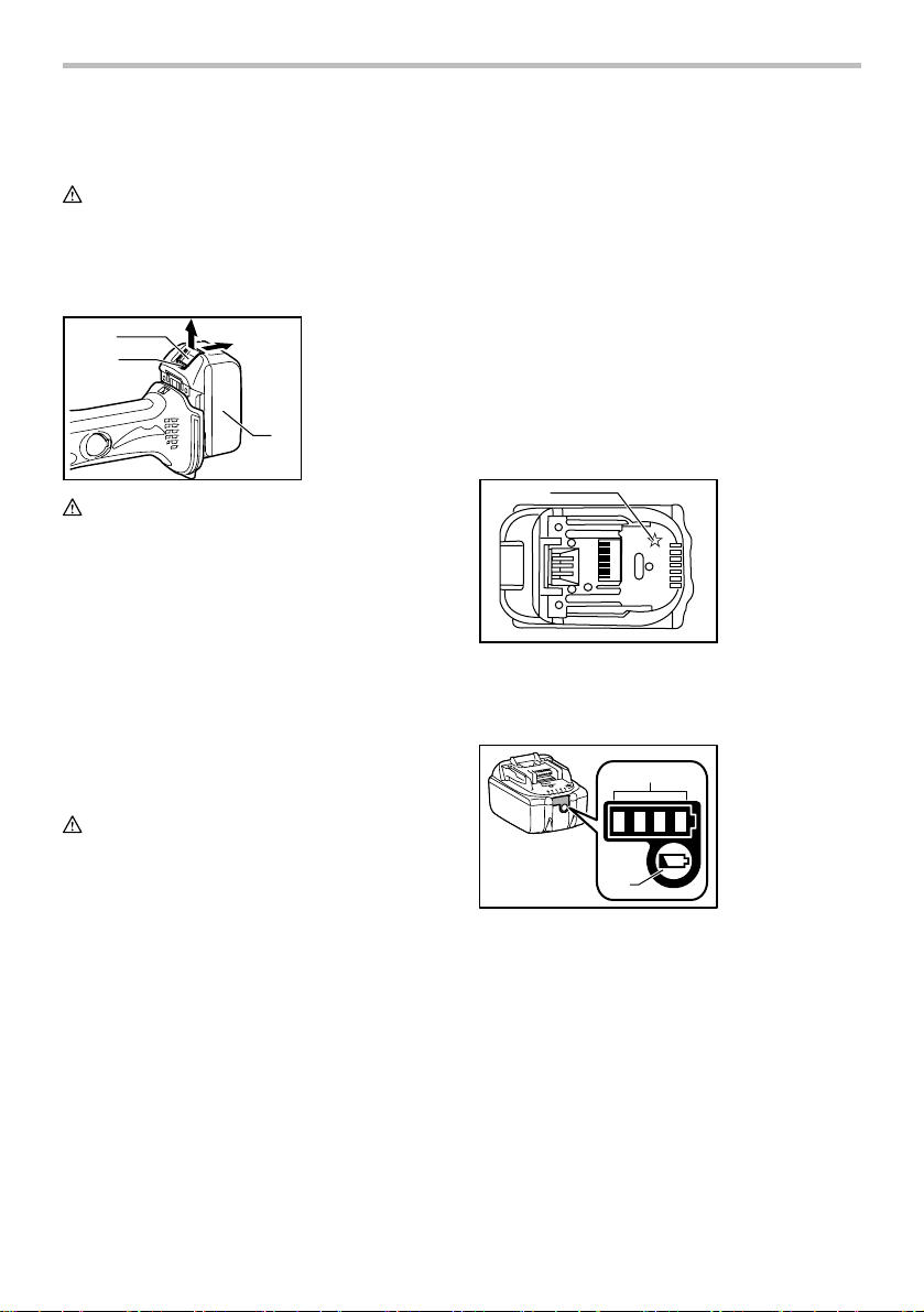
To remove the battery cartridge, slide it from the tool
while sliding the button on the front of the cartridge.
To install the battery cartridge, align the tongue on the
battery cartridge with the groove in the housing and slip
it into place. Insert it all the way until it locks in place with
a little click. If you can see the red indicator on the upper
side of the button, it is not locked completely.
CAUTION:
• Always install the battery cartridge fully until the
red indicator cannot be seen. If not, it may
accidentally fall out of the tool, causing injury to
you or someone around you.
• Do not install the battery cartridge forcibly. If the
cartridge does not slide in easily, it is not being
inserted correctly.
Battery protection system
The tool is equipped with a battery protection system.
This system automatically cuts off power to the motor to
extend battery life.
The tool will automatically stop during operation if the
tool and/or battery are placed under one of the following
conditions:
1. Button
2. Red indicator
3. Battery cartridge
3
Failure to
• Overloaded:
The tool is operated in a manner that causes
it to draw an abnormally high current.
In this situation, turn the tool off and stop the
application that caused the tool to become
overloaded. Then turn the tool on to restart.
If the tool does not start, the battery is
overheated. In this situation, let the battery
cool before turning the tool on again.
• Low battery voltage:
The remaining battery capacity is too low and
the tool will not operate. In this situation,
remove and recharge the battery.
NOTE:
The overheat protection works only with a battery
cartridge with a star mark.
1
012128
1. Star marking
Indicating the remaining battery capacity
(Only for battery cartridges with "B" at the end of the
model number.)
1. Indicator lamps
1
2
015676
Press the check button on the battery cartridge to
indicate the remaining battery capacity. The indicator
lamps light up for few seconds.
2. CHECK button
5
Page 6
015658
Indicator lamps
Off
BlinkingLighted
Remaining
capacity
75% to 100%
50% to 75%
25% to 50%
0% to 25%
Charge the
battery.
The battery
may have
malfunctioned.
NOTE:
• Depending on the conditions of use and the
ambient temperature, the indication may differ
slightly from the actual capacity.
Indication lamp with multi function
1. Indication lamp
1
012513
Indication lamps are located in two positions.
When the battery cartridge is inserted on the tool with
the slide switch positioned in the "O (OFF)" position, the
indication lamp flickers quickly for approximately one
second. If it does not flicker so, the battery cartridge or
indication lamp has broken.
− Overload protection
− When the tool is overloaded, the indication
lamp lights up. When the load on the tool is
reduced, the lamp goes out.
− If the tool continues to be overloaded and the
indication lamp continues to light up for
approximately two seconds, the tool stops.
This prevents the motor and its related parts
from being damaged.
− In this case, to start the tool again, move the
slide switch to the "O (OFF)" position once
and then to the "I (ON)" position.
− Battery cartridge replacing signal
− When the remaining battery capacity gets
small, the indicator lamp lights up during
operation earlier than enough capacity
battery use.
− Accidental re-start preventive function
− Even if the battery cartridge is inserted on the
tool with the slide switch in the "I (ON)"
position, the tool does not start. At this time,
the lamp flickers slowly and this shows that
the accidental re-start preventive function is
at work.
− To start the tool, first slide the slide switch
toward the "O (OFF)" position and then slide
it toward the "I (ON)" position.
Adjusting the depth of groove
3
2
012682
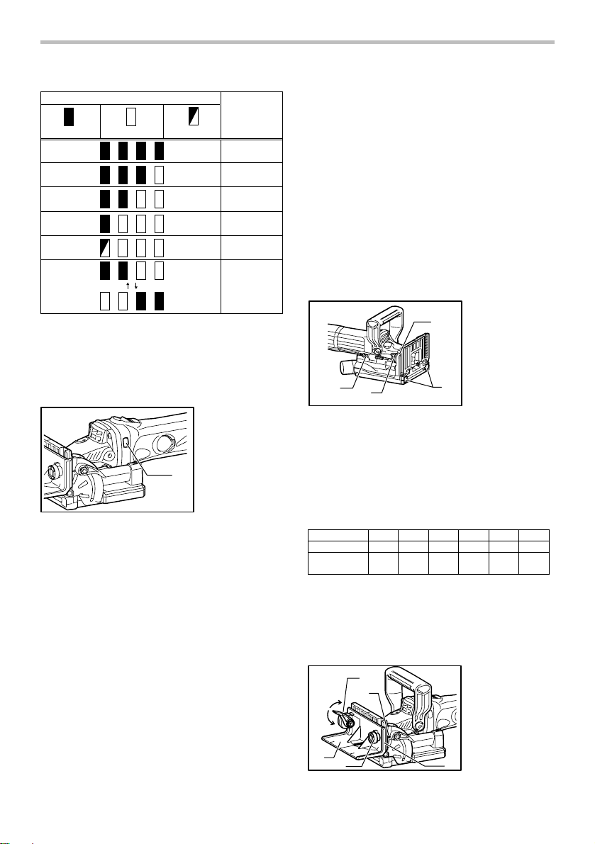
6 grooving depths can be preset according to the size of
biscuit to be used.
Refer to the table below for the correspondence
between the sizes marked on the stopper and the biscuit
size. Fine adjustments to the grooving depth can be
made by turning the adjusting screw after loosening the
hex nut. This may become necessary after the blade has
been resharpened a few times.
Size on stopper 0 10 20 S D MAX
Biscuit size 0 10 20
Depth of groove
* With the rubber spikes removed.
012683
8 mm
(0.3")
10 mm
(0.4")
1. Pointer
2. Stopper
1
3. Adjusting screw
4. Rubber spike
4
---
12.3mm
(0.48")
13 mm
(0.51")
14.7mm
(0.58")
Angle guide
The angle guide height can be moved up and down to
adjust the position of the blade in relation to the top of
the workpiece.
1. Lock lever
2. Angle guide
3. Knob
4. Scale
5. Pointer
6. Tighten
7. Loosen
4
6
2
012497
1
5
6
7
3
20 mm
(0.8")
*
Page 7
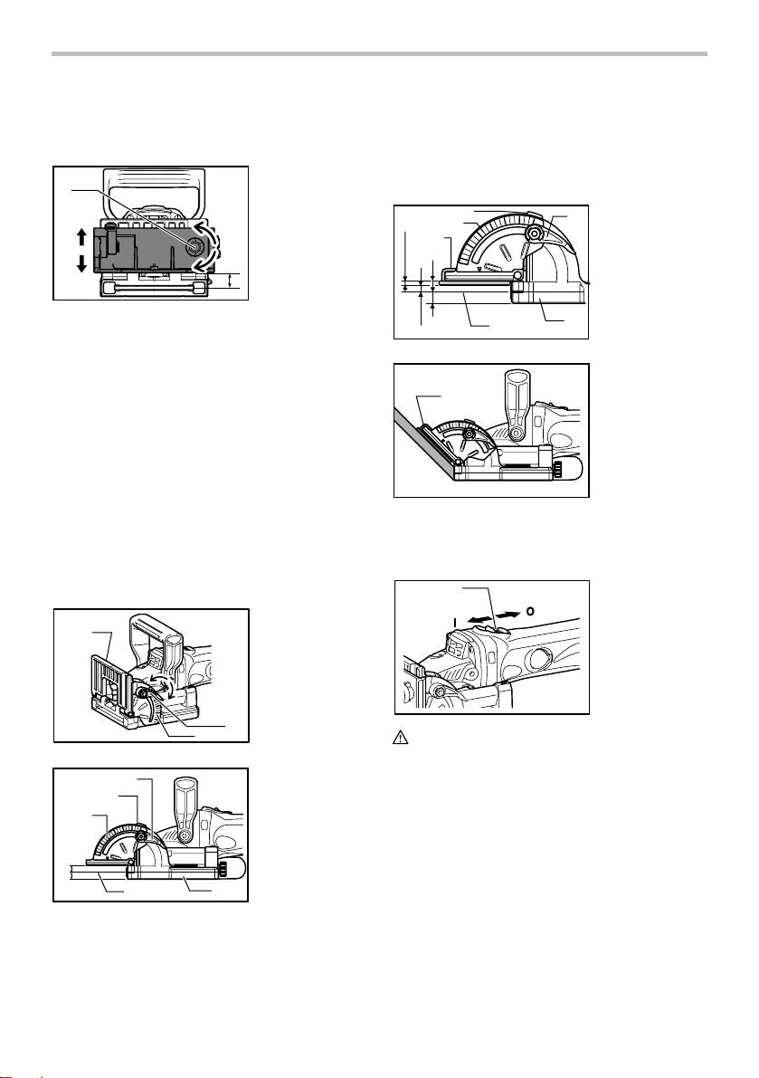
To adjust the angle guide height, loosen the lock lever
down and rotate the knob until the pointer points to the
desired scale graduation marked on the angle guide.
1. Knob
1
2. Down
3. Up
4. Center of blade
2
thickness
3
4
012498
Then tighten the lock lever up to secure the angle guide.
The scale on the angle guide indicates the distance from
the top of the workpiece to the center of the blade
thickness.
The angle guide is removable from the fence according
to the need of your work. To remove the angle guide,
loosen the lock lever and turn the knob clockwise until it
comes out of the upper end of the fence.
Fence
NOTE:
• Remove the angle guide according to the need of
your work when using the tool with the angle of the
fence adjusted to other than 0 ゚. When you need to
use the angle guide under the above condition, be
sure to adjust the depth of groove to get a proper
depth.
1. Fence
1
5
2. Angle scale
3. Lock lever
4. Tighten
5. Loosen
4
3
2
012499
10mm
10mm
012500
1
2
3
45
1. Lock lever
2. Pointer
3. Angle scale
4. Center of blade
thickness
5. Blade cover
The angle of the fence can be adjusted between 0° and
90° (positive stops at 0°, 45° and 90°). To adjust the
angle, loosen the lock lever and tilt the fence until the
pointer points to the desired graduation on the angle
scale. Then tighten the lock lever to secure the fence.
When the fence is set at 90°, both the distance from the
center of the blade thickness to the fence and the
distance from the center of the blade thickness to the
bottom of the blade cover are 10 mm (0.4").
Set plate
10mm
10mm
2
3
4
6
5:
6mm
012258
4mm
1
012501
Use the set plate as shown in the figures when cutting
slots in thin workpieces.
1. Lock lever
1
2. Pointer
3. Angle scale
4. Set plate
5. Thickness of set
plate
6. Center of blade
thickness
7
7. Blade cover
1. Set plate
Switch action
1
012512
CAUTION:
• Before installing the battery cartridge into the tool,
always check to see that the slide switch actuates
properly and returns to the "OFF" position when
the rear of the slide switch is depressed.
• Switch can be locked in "ON" position for ease of
operator comfort during extended use. Apply
caution when locking tool in "ON" position and
maintain firm grasp on tool.
To start the tool, slide the slide switch toward the "I (ON)"
position. For continuous operation, press the front of the
slide switch to lock it.
To stop the tool, press the rear of the slide switch, then
slide it toward the "O (OFF)" position.
1. Slide switch
7
Page 8
ASSEMBLY
CAUTION:
• Always be sure that the tool is switched off and the
battery cartridge is removed before carrying out
any work on the tool.
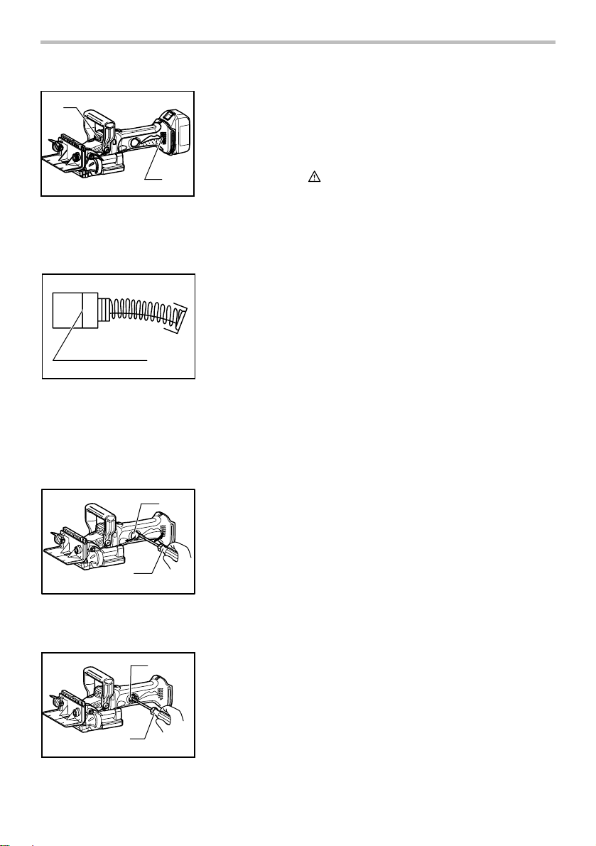
Removing or installing the blade
1
8
7
6
5
012502
CAUTION:
•
When installing the plate joiner blade, mount the inner
flange with the side marked "22" facing toward you.
To remove the blade, loosen the clamp screw and open
the blade cover. Push the shaft lock and loosen the lock
nut using the lock nut wrench. To install the blade, first
mount the inner flange.
Then mount the blade and the lock nut. Securely tighten
the lock nut using the lock nut wrench. Close the blade
cover and tighten the clamp screw to secure the blade
cover.
CAUTION:
• Use only Makita lock nut wrench provided to
remove or install the blade.
• Always check the depth of groove after replacing
the blade. Reajust it if necessary.
Dust bag
1
1. Lock nut
2
2. Plate joiner
3
blade
4
3. Blade cover
4. Inner flange
5. Clamp screw
6. Shaft lock
7. Loosen
8. Tighten
1. Dust bag
2. Fastener
3. Dust nozzle
NOTE:
• If you connect a Makita vacuum cleaner to your
plate joiner, more efficient and cleaner operations
can be performed.
OPERATION
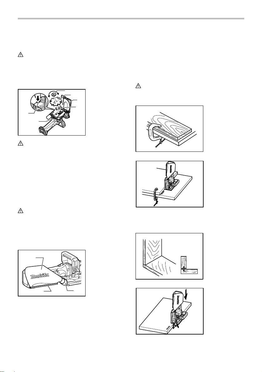
How to make joints
WARNING:
• Always clamp the workpiece to the workbench
before each operation.
004589
012504
Corner Joint (Fig. A)
Fig. A
2
012503
3
To attach the dust bag, fit it onto the dust nozzle. If the
dust bag becomes an obstacle to your work, turn the
dust nozzle to change the dust bag position.
When the dust bag is about half full, switch off and remove
the battery cartridge. Remove the dust bag from the tool
and pull the bag's fastener out. Empty the dust bag by
tapping it lightly to remove as much of the dust as possible.
8
004584
012505
Page 9
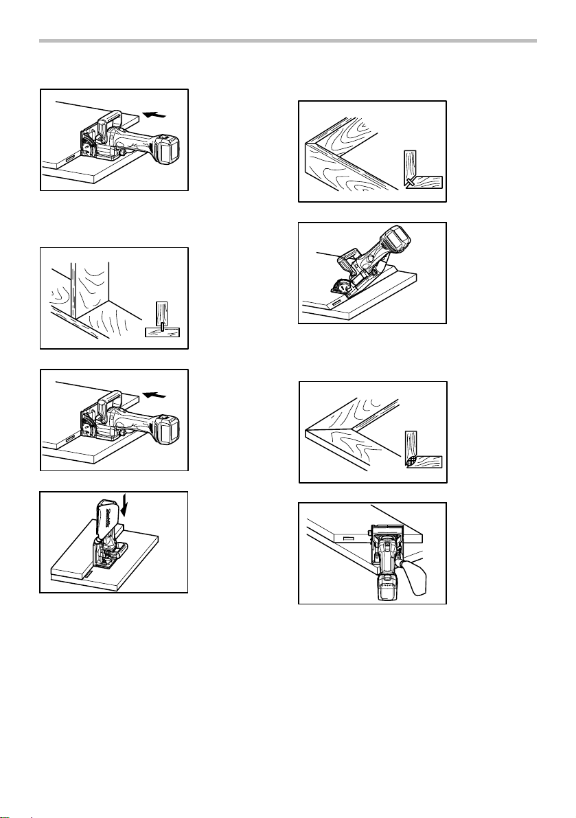
Miter Joint (Fig. C)
Fig. C
012506
T-Butt Joint (Fig. B)
004585
012506
Fig. B
004586
012508
Frame Joint (Fig. D)
004587
Fig. D
012507
9
012509
Page 10
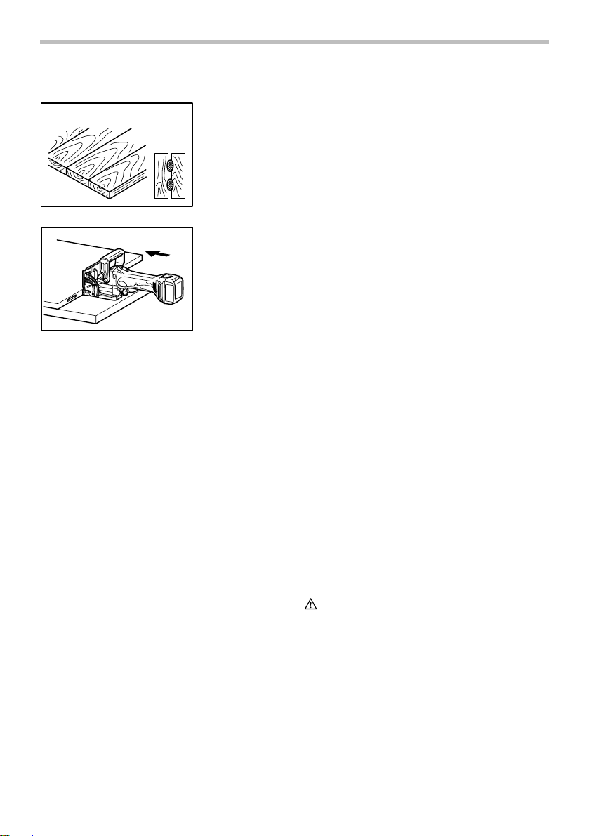
Edge-To-Edge Joint (Fig. E)
Fig. E
004588
012506
To make joints, proceed as follows:
1. Fit the two workpieces together as they will
appear in the finished joint position.
2. Mark the center of the intended biscuit grooves on
the workpiece using a pencil.
NOTE:
•
The center of grooves should be at least 50 mm
(2") from the outer edge of the workpieces.
• Allow 100 mm - 150 mm (4"-6") between
grooves in multiple biscuit application.
3. For Corner Joint and T-Butt Joint only
Clamp the vertical workpiece to the
workbench.
For Miter Joint only
Clamp one workpiece to the workbench with
the mitered edge facing up.
For Frame Joint and Edge-To-Edge Joint only
Clamp one workpiece to the workbench.
4. Set the depth of groove according to the size of
biscuit to be used. Refer to the table in the
"Adjusting the depth of groove" section.
5. Adjust the angle guide height so that the blade is
centered in the board thickness.
6. Align the center mark on the base with the pencil
line on the workpiece.
7. Switch on the tool and gently push it forward to
extend the blade into the workpiece.
8. Gently return the tool to the original position after
the adjusting screw reaches the stopper.
9. For Corner Joint and T-Butt Joint only
Clamp the horizontal workpiece to the
workbench.
For Miter Joint only
Clamp the other workpiece to the workbench
with the mitered edge facing up.
For Frame Joint and Edge-To-Edge Joint only
Clamp the other workpiece to the workbench.
10. For Corner Joint only
Place the tool on the workpiece so that the
blade is facing down.
For T-Butt Joint only
Remove the angle guide from the tool. Place
the tool on the workpiece so that the blade is
facing down.
11. Repeat the steps 6 - 8 to groove in the horizontal
or the other workpiece.
If you do not need to center the blade in the board
thickness, proceed as follows:
For Corner Joint, Miter Joint, Frame Joint and
Edge-To-Edge Joint only
• Remove the angle guide from the tool. Set the
fence at 90° for Corner Joint, Frame Joint and
Edge-To-Edge Joint or at 45° for Miter Joint.
• Follow steps 1 - 11 excluding steps 5 and 10
described above.
For T-Butt Joint only
• Fit the two workpieces together as they will appear
in the finished joint position.
• Lay the vertical workpiece on the horizontal one.
Clamp both workpieces to the workbench.
• Remove the angle guide from the tool.
• Follow the steps 2, 4, 6, 7, 8 and 11 described
above.
MAINTENANCE
CAUTION:
• Always be sure that the tool is switched off and the
battery cartridge is removed before attempting to
perform inspection or maintenance.
• Never use gasoline, benzine, thinner, alcohol or
the like. Discoloration, deformation or cracks may
result.
10
Page 11
1
1. Exhaust vent
2. Inhalation vent
2
012519
The tool and its air vents have to be kept clean.
Regularly clean the tool's air vents or whenever the
vents start to become obstructed.
Replacing carbon brushes
1. Limit mark
1
001145
Remove and check the carbon brushes regularly.
Replace when they wear down to the limit mark. Keep
the carbon brushes clean and free to slip in the holders.
Both carbon brushes should be replaced at the same
time. Use only identical carbon brushes.
Insert the top end of slotted bit screwdriver into the notch
in the tool and remove the holder cap cover by lifting it up.
1. Holder cap
1
cover
2. Screwdriver
To maintain product SAFETY and RELIABILITY, repairs,
any other maintenance or adjustment should be
performed by Makita Authorized or Factory Service
Centers, always using Makita replacement parts.
OPTIONAL ACCESSORIES
CAUTION:
• These accessories or attachments are
recommended for use with your Makita tool
specified in this manual. The use of any other
accessories or attachments might present a risk of
injury to persons. Only use accessory or
attachment for its stated purpose.
If you need any assistance for more details regarding
these accessories, ask your local Makita Service Center.
• Angle guide
• Dust bag
• Set plate
• Lock nut wrench
• Plate joiner blades
• Makita genuine battery and charger
NOTE:
• Some items in the list may be included in the tool
package as standard accessories. They may differ
from country to country.
2
012514
Use a screwdriver to remove the brush holder caps.
Take out the worn carbon brushes, insert the new ones
and secure the brush holder caps.
1
1. Brush holder
cap
2. Screwdriver
2
012515
Reinstall the holder cap cover on the tool.
11
Page 12

MAKITA LIMITED ONE YEAR WARRANTY
Warranty Policy
Every Makita tool is thoroughly inspected and tested
before leaving the factory. It is warranted to be free of
defects from workmanship and materials for the period
of ONE YEAR from the date of original purchase.
Should any trouble develop during this one year period,
return the COMPLETE tool, freight prepaid, to one of
Makita’s Factory or Authorized Service Centers. If
inspection shows the trouble is caused by defective
workmanship or material, Makita will repair (or at our
option, replace) without charge.
This Warranty does not apply where:
repairs have been made or attempted by others:
repairs are required because of normal wear and
tear:
the tool has been abused, misused or improperly
maintained:
alterations have been made to the tool.
IN NO EVENT SHALL MAKITA BE LIABLE FOR ANY
INDIRECT, INCIDENTAL OR CONSEQUENTIAL
DAMAGES FROM THE SALE OR USE OF THE
PRODUCT. THIS DISCLAIMER APPLIES BOTH
DURING AND AFTER THE TERM OF THIS
WARRANTY.
MAKITA DISCLAIMS LIABILITY FOR ANY IMPLIED
WARRANTIES, INCLUDING IMPLIED WARRANTIES
OF "MERCHANTABILITY" AND "FITNESS FOR A
SPECIFIC PURPOSE," AFTER THE ONE YEAR TERM
OF THIS WARRANTY.
This Warranty gives you specific legal rights, and you
may also have other rights which vary from state to
state. Some states do not allow the exclusion or
limitation of incidental or consequential damages, so
the above limitation or exclusion may not apply to you.
Some states do not allow limitation on how long an
implied warranty lasts, so the above limitation may not
apply to you.
EN0006-1
12
Page 13

FRANÇAIS (Mode d’emploi original)
SPÉCIFICATIONS
Modèle DPJ180
Format de lame
Profondeur de rainure max. 20 mm (3/4")
Vitesse à vide (T/MIN) 6 500 /min
Longueur totale 351 mm (13-3/4")
Tension nominale C.C. 18 V
Batterie standard
• Étant donné l'évolution constante de notre programme de recherche et de développement, les spécifications contenues dans ce
manuel sont sujettes à modification sans préavis.
• Les caractéristiques techniques et la batterie peuvent varier suivant les pays.
• Poids, batterie comprise, conforme à la procédure EPTA de 01/2003
Consignes de sécurité générales
pour outils électriques
MISE EN GARDE Veuillez lire toutes les mises en
garde de sécurité et toutes les instructions.
des mises en garde et des instructions comporte un risque de
choc électrique, d'incendie et/ou de blessure grave.
Conservez toutes les mises en
garde et instructions pour
référence future.
Le terme ≪ outil électrique ≫ qui figure dans les
avertissements fait référence à un outil électrique
branché sur une prise de courant (par un cordon
d'alimentation) ou alimenté par batterie (sans fil).
Sécurité de la zone de travail
1. Maintenez la zone de travail propre et bien
éclairée. Les zones de travail encombrées ou
sombres ouvrent grande la porte aux accidents.
2. N'utilisez pas les outils électriques dans les
atmosphères explosives, par exemple en
présence de liquides, gaz ou poussières
inflammables. Les outils électriques produisent
des étincelles au contact desquelles la poussière
ou les vapeurs peuvent s'enflammer.
3. Assurez-vous qu'aucun enfant ou curieux ne
s'approche pendant que vous utilisez un outil
électrique. Vous risquez de perdre la maîtrise de
l'outil si votre attention est détournée.
Sécurité en matière d'électricité
4. Les fiches d'outil électrique sont conçues
pour s'adapter parfaitement aux prises de
courant. Ne modifiez jamais la fiche de
quelque façon que ce soit. N'utilisez aucun
Lame pour lamelleuse
(dia. externe x largeur x dia. arbre)
Poids net 3,0 kg (6,7 lbs)
BL1830 / BL1830B / BL1840 / BL1840B / BL1850 / BL1850B / BL1860B
GEA006-2
L'ignorance
adaptateur de fiche sur les outils électriques
avec mise à la terre. En ne modifiant pas les
fiches et en les insérant dans des prises de
courant pour lesquelles elles ont été conçues
vous réduirez les risques de choc électrique.
5. Évitez tout contact corporel avec les surfaces
mises à la terre, telles que les tuyaux,
radiateurs, cuisinières et réfrigérateurs. Le
risque de choc électrique est plus élevé si votre
corps se trouve mis à la terre.
6. N'exposez pas les outils électriques à la pluie
ou à l'eau. La présence d'eau dans un outil
électrique augmente le risque de choc électrique.
7.
Ne maltraitez pas le cordon. N'utilisez jamais le
cordon pour transporter, tirer ou débrancher
l'outil électrique. Maintenez le cordon à l'écart
des sources de chaleur, de l'huile, des objets à
bords tranchants et des pièces en mouvement.
Le risque de choc électrique est plus élevé lorsque
les cordons sont endommagés ou enchevêtrés.
8.
Lorsque vous utilisez un outil électrique à
l'extérieur, utilisez un cordon prolongateur prévu à
cette fin.
lorsqu'un cordon conçu pour l'extérieur est utilisé.
9. Si vous devez utiliser un outil électrique dans
un endroit humide, utilisez une source
d'alimentation protégée par un disjoncteur de
fuite à la terre. L'utilisation d'un disjoncteur de
fuite à la terre réduit le risque de choc électrique.
Sécurité personnelle
10.
Restez alerte, attentif à vos mouvements et faites
preuve de bon sens lorsque vous utilisez un outil
électrique. Évitez d'utiliser un outil électrique si
vous êtes fatigué ou si vous avez pris une drogue,
de l'alcool ou un médicament.
d'inattention pendant l'utilisation d'un outil électrique
100 mm x 4 mm x 22 mm
(4" x 5/32" x 7/8")
Les risques de choc électrique sont moindres
Un moment
13
Page 14

peut entraîner une grave blessure.
11. Portez des dispositifs de protection
personnelle. Portez toujours un protecteur
pour la vue. Les risques de blessure seront
moins élevés si vous utilisez des dispositifs de
protection tels qu'un masque antipoussières, des
chaussures à semelle antidérapante, une coiffure
résistante ou une protection d'oreilles.
12.
Évitez les démarrages accidentels. Assurez-vous
que l’interrupteur soit en position d'arrêt avant de
brancher l'outil à la prise électrique et/ou au
bloc-piles, avant de prendre ou de transporter
l’outil.
Vous ouvrez la porte aux accidents si vous
transportez les outils électriques avec le doigt sur
l’interrupteur ou si vous les branchez alors que
l’interrupteur est en position de marche.
13. Retirez toute clé de réglage ou de serrage
avant de mettre l'outil sous tension. Toute clé
laissée en place sur une pièce rotative de l'outil
électrique peut entraîner une blessure.
14. Maintenez une bonne position. Assurez-vous
d'une bonne prise au sol et d'une bonne
position d'équilibre en tout temps. Cela vous
permettra d'avoir une meilleure maîtrise de l'outil
dans les situations imprévues.
15. Portez des vêtements adéquats. Ne portez ni
vêtements amples ni bijoux. Vous devez
maintenir cheveux, vêtements et gants à
l'écart des pièces en mouvement. Les pièces
en mouvement peuvent happer les vêtements
amples, les bijoux et les cheveux longs.
16. Si des accessoires sont fournis pour
raccorder un appareil d'aspiration et de
collecte de la poussière, assurez-vous qu'ils
sont correctement raccordés et qu'ils sont
utilisés de manière adéquate. L'utilisation d'un
appareil d'aspiration permet de réduire les risques
liés à la présence de poussière dans l'air.
Utilisation et entretien des outils électriques
17. Ne forcez pas l'outil électrique. Utilisez l'outil
électrique adéquat suivant le type de travail à
effectuer. Si vous utilisez l'outil électrique
adéquat et respectez le régime pour lequel il a été
conçu, il effectuera un travail de meilleure qualité
et de façon plus sécuritaire.
18.
N'utilisez pas l'outil électrique s'il n'est pas possible
de mettre sa gâchette en position de marche et
d'arrêt.
Un outil électrique dont l'interrupteur est
défectueux représente un danger et doit être réparé.
19.
Débranchez la fiche de la source d'alimentation
et/ou retirez le bloc-piles de l'outil électrique
avant d'effectuer tout réglage, de changer un
accessoire ou de ranger l'outil électrique.
De
telles mesures préventives réduisent les risques de
démarrage accidentel de l'outil électrique.
20. Après l'utilisation d'un outil électrique,
rangez-le hors de portée des enfants et ne
laissez aucune personne l'utiliser si elle n'est
pas familiarisée avec l'outil électrique ou les
présentes instructions d'utilisation. Les outils
électriques représentent un danger entre les
mains de personnes qui n'en connaissent pas le
mode d'utilisation.
21. Veillez à l’entretien des outils électriques.
Assurez-vous que les pièces mobiles ne sont
pas désalignées ou coincées, qu’aucune pièce
n’est cassée et que l’outil électrique n’a subi
aucun dommage affectant son bon
fonctionnement. Le cas échéant, faites réparer
l'outil électrique avant de l'utiliser. De
nombreux accidents sont causés par des outils
électriques mal entretenus.
22. Maintenez les outils tranchants bien aiguisés
et propres. Un outil tranchant dont l'entretien est
effectué correctement et dont les bords sont bien
aiguisés risquera moins de se coincer et sera plus
facile à maîtriser.
23. Utilisez l'outil électrique, ses accessoires, ses
embouts, etc., en respectant les présentes
instructions, en tenant compte des conditions
de travail et du type de travail à effectuer.
L'utilisation d'un outil électrique à des fins autres
que celles prévues peut entraîner une situation
dangereuse.
Utilisation et entretien des outils alimentés par
batterie
24. Pour recharger, utilisez uniquement le
chargeur spécifié par le fabricant. L'utilisation
d'un chargeur conçu pour un type donné de
bloc-piles comporte un risque d'incendie lorsqu'il
est utilisé avec un autre type de bloc-piles.
25. N'utilisez un outil électrique qu'avec le
bloc-piles conçu spécifiquement pour cet outil.
Il y a risque de blessure ou d'incendie si un autre
bloc-piles est utilisé.
26. Lorsque vous n'utilisez pas le bloc-piles,
rangez-le à l'écart des objets métalliques tels
que trombones, pièces de monnaie, clés,
clous, vis ou autres petits objets métalliques
qui risquent d'établir une connexion entre les
bornes. La mise en court-circuit des bornes de
batterie peut causer des brûlures ou un incendie.
27. Dans des conditions d'utilisation inadéquates
de la batterie, il peut y avoir fuite d'électrolyte;
évitez tout contact avec ce liquide. En cas de
contact accidentel, rincez avec beaucoup
d’eau. Si le liquide pénètre dans vos yeux, il
faut aussi consulter un médecin. L'électrolyte
qui s'échappe de la batterie peut causer des
irritations ou des brûlures.
14
Page 15

Réparation
28. Faites réparer votre outil électrique par un
réparateur qualifié qui utilise des pièces de
rechange identiques aux pièces d'origine. Le
maintien de la sûreté de l'outil électrique sera
ainsi assuré.
29. Suivez les instructions de lubrification et de
changement des accessoires.
30. Maintenez les poignées de l'outil sèches,
propres et exemptes d'huile ou de graisse.
GEB093-1
CONSIGNES DE SÉCURITÉ POUR
LA LAMELLEUSE SANS FIL
1. Les lames doivent être réglées au minimum
sur la vitesse indiquée sur l’outil. Les lames
tournant au-dessus de la vitesse nominale
peuvent se détacher et causer des blessures.
2.
Utilisez toujours le protecteur.
protège l'utilisateur contre les fragments de lame
cassée et contre tout contact accidentel avec la lame.
3. Utilisez uniquement les lames spécifiées pour
cet outil.
4. N'utilisez jamais l'outil sans que le couvercle
de lame n'ait été refermé au préalable, et
solidement verrouillé dans cette position.
5. Avant la mise en route, assurez vous que la
lame coulisse librement et sans entrave dans
son logement.
6. Vérifiez attentivement la présence de fissures
ou de dommages sur les fers avant d'utiliser
l'outil. Remplacez immédiatement tout fer
fissuré ou endommagé.
7. Assurez-vous que le flasque s'ajuste bien à
l'orifice de l'arbre lorsque vous installez la
lame.
8. Avant de travailler votre pièce, inspectez-la et
retirez-en tous les clous ou matériaux autres
que la pièce elle-même.
9. Placez toujours les pièces sur un établi stable.
10. Fixez fermement les pièces à travailler au
moyen d'un dispositif de serrage ou d'un étau.
11. Ne portez JAMAIS de gants pendant
l'utilisation de cet outil.
12. Tenez l'outil fermement à deux mains.
13. Éloignez vos mains et votre corps de la zone
de rainurage.
14. Faites tournez l'outil un instant, en ne pointant
la lame vers personne. Soyez attentif à toute
vibration ou sautillement pouvant indiquer
que la lame n'est pas bien installée ou est mal
équilibrée.
15. Ne placez jamais vos mains sous la pièce
alors que la lame tourne.
Le protecteur
16.
Ne laissez pas l'outil tourner sans surveillance.
17. Assurez-vous toujours que l’outil est hors
tension et que sa batterie est retirée avant
d’effectuer des réglages ou de remplacer la
lame.
18. Certains matériaux contiennent des produits
chimiques qui peuvent être toxiques. Prenez
les précautions nécessaires pour éviter
l'inhalation de ces poussières ou leur contact
avec la peau. Conformez-vous aux consignes
de sécurité du fournisseur du matériau.
19. N'utilisez pas les lames émoussées ou
endommagées.
20. N'utilisez jamais l'outil avec des protecteurs
endommagés.
CONSERVEZ CE MODE
D'EMPLOI.
AVERTISSEMENT:
NE VOUS LAISSEZ PAS tromper (au fil d'une
utilisation répétée) par un sentiment d'aisance ou de
familiarité avec le produit en négligeant les
consignes de sécurité qui accompagnent le produit.
L’utilisation non sécuritaire ou incorrecte de cet
outil comporte un risque de blessure grave.
USD301-4
Symboles
Les symboles utilisés pour l'outil sont indiqués
ci-dessous.
・ volts
・ courant continu
・ vitesse nominale
・ vitesse à vide
・ tours ou alternances par minute
ENC007-11
CONSIGNES DE SÉCURITÉ
IMPORTANTES
POUR LA BATTERIE
1. Avant d'utiliser la batterie, lisez toutes les
instructions et précautions relatives (1) au
chargeur de batterie, (2) à la batterie, et (3) à
l'outil utilisant la batterie.
2. Ne démontez pas la batterie.
15
Page 16

3. Cessez immédiatement l'utilisation si le temps
de fonctionnement devient excessivement
court. Il y a risque de surchauffe, de brûlures,
voire d'explosion.
4. Si l'électrolyte pénètre dans vos yeux,
rincez-les à l'eau claire et consultez
immédiatement un médecin. Il y a risque de
perte de la vue.
5. Ne court-circuitez pas la batterie :
(1) Ne touchez les bornes avec aucun
matériau conducteur.
(2) Évitez de ranger la batterie dans un
conteneur avec d'autres objets
métalliques, par exemple des clous, des
pièces de monnaie, etc.
(3) Évitez d'exposer la batterie à l'eau ou à la
pluie.
Un court-circuit de la batterie pourrait
provoquer un fort courant, une surchauffe,
parfois des brûlures et même une panne.
6. Ne rangez pas l'outil ou la batterie dans des
endroits où la température risque d'atteindre
ou de dépasser 50 ゚ C (122 ゚ F).
7. Ne jetez pas la batterie au feu même si elle est
sérieusement endommagée ou complètement
épuisée. La batterie peut exploser au contact
du feu.
8. Prenez garde d'échapper ou de heurter la
batterie.
9. N'utilisez pas une batterie si elle est
endommagée.
10. Les batteries au lithium-ion contenues sont
soumises aux exigences des lois applicables
concernant les matières dangereuses.
Pour le transport commercial, p. ex. par des
entreprises de transport tiers, il est nécessaire de
respecter certaines mesures particulières ayant
trait à l'emballage et à l'étiquetage.
L'assistance d'un expert en matières
dangereuses est requise pour la préparation de
l'article à expédier. Veuillez également vous
conformer aux réglementations nationales en
vigueur qui pourraient être plus détaillées.
Masquez les contacts découverts ou couvrez-lez
de ruban, et emballez la batterie de façon à ce
qu'elle ne puisse se déplacer à l'intérieur du
paquet.
11. Suivez la réglementation locale concernant la
mise au rebut de la batterie.
CONSERVEZ CE MODE
D'EMPLOI.
ATTENTION : Utilisez uniquement des batteries
Makita d'origine.
L'utilisation de batteries autres que les batteries
d'origine Makita ou de batteries qui ont été modifiées
peut entraîner l'explosion de la batterie et provoquer des
incendies, blessures et autres dommages. Cela
annulerait également la garantie de Makita s'appliquant
à l'outil Makita et au chargeur.
Conseils pour obtenir la durée de service
maximale de la batterie
1. Rechargez la batterie avant qu'elle ne soit
complètement déchargée.
Arrêtez toujours l'outil et rechargez la batterie
quand vous remarquez que la puissance de
l'outil diminue.
2. Ne rechargez jamais une batterie
complètement chargée.
La surcharge réduit la durée de service de la
batterie.
3. Rechargez la batterie à une température
ambiante comprise entre 10 ゚ C et 40 ゚ C (50 ゚
F - 104 ゚ F). Si la batterie est chaude, laissez-la
refroidir avant de la recharger.
4. Rechargez la batterie si vous ne l'utilisez pas
pendant une période prolongée (plus de six
mois).
16
Page 17

DESCRIPTION DU
FONCTIONNEMENT
ATT EN TI ON :
• Assurez-vous toujours que l'outil est hors tension
et que sa batterie est retirée avant de l'ajuster ou
de vérifier son fonctionnement.
Installation ou retrait de la batterie
1
2
012517
ATT EN TI ON :
• Mettez toujours l'appareil hors tension avant
d'installer ou de retirer la batterie.
• Tenez fermement l'outil et la batterie lors de
l'installation ou du retrait de cette dernière.
Sinon, l'outil et la batterie pourraient vous glisser
des mains, ce qui risque d'endommager l'outil et la
batterie, ou encore de provoquer des blessures.
Pour retirer la batterie, faites-la glisser de l'outil tout en
faisant glisser le bouton se trouvant à l'avant.
Pour installer la batterie, alignez sa languette sur la
rainure pratiquée dans le boîtier, et glissez la batterie en
place. Insérez-la à fond jusqu'à ce que vous entendiez
un clic. Si vous pouvez voir l'indicateur rouge situé sur le
dessus du bouton, la batterie n'est pas complètement
verrouillée.
ATT EN TI ON :
• Installez toujours la batterie à fond jusqu’à ce que
vous ne puissiez plus voir l’indicateur rouge. Dans
le cas contraire, elle pourrait tomber de l'outil et
entraîner des blessures.
• Ne forcez pas sur la batterie pour l'installer. Si la
batterie ne glisse pas facilement, c'est qu'elle n'est
pas insérée correctement.
Système de protection de la batterie
L'outil est équipé d'un système de protection de la
batterie. Ce système coupe automatiquement
l'alimentation du moteur pour augmenter la durée de vie
de la batterie.
L'outil s'arrête automatiquement pendant l'utilisation
lorsque l'outil et/ou la batterie sont dans l'une des
situations suivantes :
1. Bouton
2. Indicateur rouge
3. Batterie
3
• En surcharge :
L'outil est utilisé d'une manière entraînant
une consommation anormale de courant.
Si une telle situation se présente, mettez l’outil
hors tension et cessez l’application ayant
provoqué la surcharge de l’outil. Mettez ensuite
l’outil en position de marche pour le redémarrer.
Si l’outil ne démarre pas, il y a surchauffe de
la batterie. Si tel est le cas, laissez la batterie
refroidir avant de remettre l’outil en marche.
• Tension de la batterie faible :
La capacité restante de la batterie est trop faible
pour que l'outil puisse fonctionner. Dans cette
situation, retirez et rechargez la batterie.
NOTE:
La protection de surchauffe fonctionne uniquement avec
les batteries comportant un repère en forme d'étoile.
1
012128
1. Étoile
Affiche la capacité restante de la batterie
(Uniquement pour les batteries dont le numéro de
modèle se termine par « B ».)
1. Témoins
1
2
015676
Appuyez sur le bouton de vérification sur la batterie pour
afficher la capacité résiduelle de la batterie. Les témoins
s'allument pendant quelques secondes.
17
2. Bouton CHECK
Page 18

015658
Témoins
ARRÊT
ClignotementAllumé
Capacité
résiduelle
75 % à 100 %
50 % à 75 %
25 % à 50 %
0 % à 25 %
Chargez la
batterie.
La batterie peut
avoir présenté
un défaut de
fonctionnement.
NOTE:
• Selon les conditions d'utilisation et la température
ambiante, il est possible que la capacité relevée
soit légèrement différente par rapport à la capacité
réelle.
Témoin d'indication à fonctions multiples
1. Voyant lumineux
1
012513
Les témoins d'indication se trouvent en deux positions.
Lorsque la batterie est insérée dans l'outil avec l'interrupteur à
glissière sur la position "O" (arrêt), le témoin d'indication
clignote rapidement pendant environ une seconde. S'il ne
clignote pas ainsi, la batterie ou le témoin indicateur est cassé.
− Dispositif de protection contre la surcharge
− Lorsque l'outil est soumis à une surcharge, le
témoin d'indication s'allume. Le témoin
s'éteint lorsque la charge diminue.
− Si l'outil demeure soumis à une surcharge et
que le témoin d'indication demeure allumé
pendant environ deux secondes, l'outil
s'arrête. Cela permet d'éviter que le moteur
et les pièces qui lui sont liées ne subissent
des dommages.
− Le cas échéant, pour redémarrer l'outil,
déplacez l'interrupteur à glissière sur la
position "O" (arrêt) une fois pour ramenez-le
sur la position "I" (marche).
− Signal de remplacement de la batterie
− Lorsque la charge restante de la batterie
devient faible, le témoin indicateur s'allume
pendant l'opération plus tôt que lorsque la
charge est encore suffisante.
− Fonction de prévention du redémarrage
accidentel
− L'outil ne démarre pas même si la batterie y
est insérée et que l'interrupteur à glissière se
trouve en position "I" (marche). Le témoin
clignote alors lentement pour indiquer que la
fonction de prévention du redémarrage
accidentel est activée.
− Pour mettre l'outil en marche, glissez d'abord
l'interrupteur à glissière vers la position "O"
(arrêt) puis glissez-le vers la position "I"
(marche).
Réglage de la profondeur de rainure
1. Index
2. Butoir
1
3. Vis de réglage
4. Crampon en
caoutchouc
4
012682
3
2
6 profondeurs de rainure peuvent être préréglées selon
la taille de lamelle utilisée.
Référez-vous au tableau ci-dessous pour voir la
correspondance entre les tailles marquées sur la butée
et la taille de lamelle. Il est possible d’ajuster
précisément la profondeur de rainure en tournant la vis
de réglage après avoir desserré l’écrou hexagonal. Cela
peut être nécessaire quand la lame a été réaffûtée
plusieurs fois.
Taille sur la butée
Taille de lamelle 0 10 20
Profondeur de
rainure
* Une fois les crampons en caoutchouc retirés.
012683
0 10 20 L D MAX
8 mm
10 mm
(0,3")
(0,4")
12,3mm
(0,48")
---
13 mm
(0,51")
14,7mm
(0,58")
Guide d'angle
La hauteur du guide d’angle peut être augmentée ou
réduite pour régler la position de la lame en fonction de
la hauteur de la pièce.
20 mm
(0,8")
*
18
Page 19

1. Levier de
verrouillage
2. Guidage d’angle
3. Bouton
4. Échelle
5. Index
6. Serrer
7. Desserrer
4
2
012497
1
5
6
7
3
Pour ajuster la hauteur du guide d’angle, desserrez le
levier de verrouillage et tournez le bouton jusqu’à ce que
l’index pointe sur la valeur d’échelle désirée marquée
sur le guide d’angle.
1. Bouton
1
012498
2. Pour descendre
3. Pour monter
4. Plan médian de
2
3
l'épaisseur de la
lame
4
Puis serrez le levier de verrouillage pour immobiliser le
guide d’angle.
L'échelle graduée du guide d'angle indique la distance
qui sépare le dessus de la pièce à travailler du plan
médian de l'épaisseur de la lame.
Le guide d’angle peut être retiré de la plaque frontale
selon la tâche que vous devez effectuer. Pour retirer le
guide d’angle, desserrez le levier de verrouillage et
tournez le bouton dans le sens des aiguilles d’une
montre jusqu'à ce qu’il sorte de la partie supérieure de la
plaque frontale.
Plaque frontale
NOTE:
• Retirez le guide d’angle selon la tâche que vous
devez effectuer lorsque vous utilisez l’outil avec
l’angle de la plaque frontale ajusté sur une valeur
différente de 0 ゚. Lorsque vous devez utiliser le
guide d’angle dans les conditions susmentionnées,
assurez-vous d’ajuster l’outil sur une profondeur
de rainure correcte.
1. Plaque frontale
2. Secteur
angulaire
3. Levier de
verrouillage
4. Serrer
5. Desserrer
3
012499
1
5
4
2
1. Levier de
verrouillage
2. Index
Secteur angulaire
3.
4. Plan médian de
l'épaisseur de la
lame
5. Couvercle de
lame
10mm
10mm
012500
1
2
3
45
Vous pouvez ajuster l'angle de la plaque frontale sur une
plage de 0° à 90° (avec des arrêts fixes sur 0°, 45° et
90°). Pour ajuster l'angle, desserrez le levier de
verrouillage et inclinez la plaque frontale jusqu'à ce que
l'index soit pointé sur la valeur désirée sur le secteur
angulaire. Serrez ensuite le levier de verrouillage
fermement pour immobiliser la plaque frontale.
Lorsque la plaque frontale est réglée sur 90°, la distance
entre le centre de l'épaisseur de la lame et la plaque
frontale et la distance entre le centre de l’épaisseur de la
lame et le bas du couvercle de lame sont de 10 mm (0,4").
Plaque de fixation
10mm
10mm
2
3
4
6
5:
6mm
012258
4mm
1
012501
Utilisez la plaque de fixation de la façon indiquée sur les figures
lorsque vous coupez des entailles dans des pièces minces.
1.
Levier de verrouillage
1
2.
Index
3.
Secteur angulaire
4.
Plaque de fixation
5.
Épaisseur de la
plaque de fixation
6.
Plan médian de
l'épaisseur de la lame
7
7.
Couvercle de lame
1. Plaque de
fixation
Interrupteur
1
012512
19
1. Interrupteur à
glissière
Page 20

ATT EN TI ON :
• Avant d'installer la batterie dans l'outil, vérifiez
toujours que l’interrupteur à glissière fonctionne
correctement et qu'il revient en position "OFF"
quand vous en relâchez l’arrière.
•
Pour rendre le travail de l'utilisateur plus confortable
lors d'une utilisation prolongée, l'interrupteur peut être
verrouillé en position de marche. Soyez prudent
lorsque vous verrouillez l'outil en position de marche,
et maintenez une poigne solide sur l'outil.
Pour mettre l'outil en marche, faites glisser l'interrupteur
à glissière vers la positon d'"I (ON)". Pour une utilisation
continue, appuyez sur la partie avant de l'interrupteur à
glissière pour le verrouiller.
Pour arrêter l'outil, appuyez sur la partie arrière de
l'interrupteur à glissière, puis faites-le glisser vers la
position d'"O (OFF)".
ASSEMBLAGE
ATT EN TI ON :
• Assurez-vous toujours que l'outil est hors tension
et que sa batterie est retirée avant d'effectuer tout
travail dessus.
Pose et dépose de la lame
1
8
7
6
5
012502
ATT EN TI ON :
• Lors de l’installation de la lame pour lamelleuse,
montez le flasque intérieur avec le côté indiquant «
22 » tourné vers vous.
Pour retirer la lame, desserrez la vis de serrage et ouvrez
le couvercle de lame. Appuyez sur le blocage de l'arbre et
desserrez le contre-écrou avec la clé à contre-écrou. Pour
installer la lame, montez d'abord le flasque intérieur.
Montez ensuite la lame et le contre-écrou. Serrez
fermement le contre-écrou avec la clé à contre-écrou.
Fermez le couvercle de lame et serrez la vis de serrage
pour immobiliser le couvercle de lame.
ATT EN TI ON :
• Utilisez exclusivement la clé à contre-écrou Makita
fournie pour retirer ou installer la lame.
• Vérifiez toujours la profondeur de rainure après
avoir remplacé la lame. Réajustez-la si nécessaire.
1.
2
Contre-écrou
Lame pour lamelleuse
2.
3
3.
Couvercle de lame
4
4.
Bague interne
5.
Vis de serrage
Verrouillage de
6.
l'arbre
7.
Desserrer
8.
Serrer
Sac à poussières
1. Sac à
poussières
2. Pièce de fixation
3. Raccord à
poussières
012503
1
2
3
Pour fixer le sac à poussières, insérez-le dans le raccord
à poussières. Si le sac à poussière nuit à l'exécution de
votre travail, tournez le raccord à poussières pour
changer la position du sac.
Lorsque le sac à poussières est rempli environ à la moitié de
sa capacité, mettez l’outil hors tension et retirez la batterie.
Retirez le sac à poussières de l’outil et tirez sur la fixation du
sac pour la retirer. Videz le sac à poussières en le tapotant
pour extraire le plus de poussières possible.
NOTE:
• Si vous raccordez votre lamelleuse à un aspirateur
MAKITA, votre travail gagnera en propreté et en
efficacité.
UTILISATION
Pour effectuer des assemblages
AVERTISSEMENT:
• Fixez toujours la pièce à l’établi avant chaque
opération.
004589
012504
20
Page 21

Assemblage en angle (Fig. A)
Fig. A
004584
012505
012506
Assemblage en T (Fig. B)
Fig. B
012507
Assemblage à onglet (Fig. C)
Fig. C
004586
012508
Assemblage de cadre (Fig. D)
Fig. D
004585
012506
21
004587
Page 22

012509
Assemblage chant sur chant (Fig. E)
Fig. E
004588
012506
Pour effectuer des assemblages, procédez comme suit :
1. Présentez les deux pièces dans la position qui
sera la leur une fois l'assemblage réalisé.
2. Marquez le centre des rainures de lamelle
prévues sur la pièce avec un crayon.
NOTE:
• Le centre des rainures doit être au moins à 50
mm (2") du bord extérieur des pièces.
• Laissez un espace de 100 mm à 150 mm (4" à
6") entre les rainures si vous installez
plusieurs lamelles.
3. Pour assemblage en angle et assemblage en T
uniquement
Fixez la pièce verticale sur l'établi.
Pour assemblage à onglet uniquement
Fixez une pièce sur l'établi avec le bord en
onglet orienté vers le haut.
Pour assemblage à cadre et assemblage chant
sur chant uniquement
Fixez une pièce sur l'établi.
4. Réglez la profondeur de rainure en fonction de la
taille de lamelle utilisée. Reportez-vous au
tableau dans la section « Réglage de la
profondeur de rainure ».
5.
Ajustez la hauteur du guide d'angle de sorte que la
lame soit centrée sur le plan médian de l'épaisseur.
6. Alignez la marque centrale de la base sur la ligne
tracée au crayon sur la pièce à travailler.
7. Mettez l'outil en marche et poussez-le doucement
vers l'avant pour que la lame atteigne la pièce à
travailler.
8. Ramenez doucement l'outil sur sa position initiale
après que la vis de réglage ait atteint la butée.
9. Pour assemblage en angle et assemblage en T
uniquement
Fixez la pièce horizontale sur l'établi.
Pour assemblage à onglet uniquement
Fixez l'autre pièce sur l'établi avec le bord en
onglet orienté vers le haut.
Pour assemblage à cadre et assemblage chant
sur chant uniquement
Fixez l'autre pièce sur l'établi.
10. Pour assemblage en angle uniquement
Placez l'outil sur la pièce de sorte que la lame
soit orientée vers le bas.
Pour assemblage en T uniquement
Enlevez le guide d'angle de la machine.
Placez la machine sur la pièce de façon à ce
que la lame soit tournée vers le bas.
11. Répétez les étapes 6 à 8 pour rainurer à
l’horizontale ou l’autre pièce.
Si vous n'avez pas besoin de centrer la lame dans
l'épaisseur de la planche, procédez comme suit :
Pour assemblage en angle, assemblage à
onglet, assemblage à cadre et assemblage
chant sur chant uniquement
• Retirez le guide d'angle de l'outil. Réglez la plaque
frontale sur 90° pour l'assemblage en angle,
l'assemblage à cadre et l'assemblage chant sur
chant, ou sur 45° pour l'assemblage à onglet.
• Suivez les étapes 1 - 11 sauf les étapes 5 et 10
décrites ci-dessus.
Pour assemblage en T uniquement
• Présentez les deux pièces dans la position qui
sera la leur une fois l'assemblage réalisé.
• Disposez la pièce verticale sur la pièce horizontale.
Fixez les deux pièces à l'établi.
22
Page 23

• Enlevez le guide d'angle de la machine.
• Suivez les étapes 2, 4, 6, 7, 8 et 11 décrites
ci-dessus.
ENTRETIEN
ATT EN TI ON :
• Assurez-vous toujours que l'outil est hors tension
et que la batterie est retirée avant d'y effectuer tout
travail d'inspection ou d'entretien.
• N'utilisez jamais d'essence, de benzine, de solvant,
d'alcool ou d'autres produits similaires. Une
décoloration, une déformation, ou la formation de
fissures peuvent en découler.
1
1. Orifice de sortie
d’air
2. Orifice d'entrée
d'air
1. Couvercle de
1
porte-charbon
2. Tournevis
2
012514
Utilisez un tournevis pour retirer les bouchons de
porte-charbon. Enlevez les charbons usés, insérez-en
de nouveaux et revissez solidement les bouchons de
porte-charbon.
1
1. Bouchon de
porte-charbon
2. Tournevis
2
012519
L'outil et ses orifices d'aération doivent être maintenus
propres. Nettoyez régulièrement les orifices d'aération
de l'outil, ou chaque fois qu'ils commencent à se
boucher.
Remplacement des charbons
1. Trait de limite
d'usure
1
001145
Retirez et vérifiez régulièrement les charbons.
Remplacez-les lorsqu'ils sont usés jusqu'au trait de
limite d'usure. Maintenez les charbons propres et en état
de glisser aisément dans les porte-charbon. Les deux
charbons doivent être remplacés en même temps.
N'utilisez que des charbons identiques.
Insérez l'extrémité du tournevis à bout fendu dans
l'entaille de l'outil et retirez le couvercle de
porte-charbon en le soulevant.
2
012515
Remettez le couvercle de porte-charbon en place sur l'outil.
Pour maintenir la SÉCURITÉ et la FIABILITÉ du produit,
les réparations, tout autre travail d'entretien ou de
réglage doivent être effectués dans un centre de service
Makita agréé ou un centre de service de l'usine Makita,
exclusivement avec des pièces de rechange Makita.
ACCESSOIRES EN OPTION
ATT EN TI ON :
• Ces accessoires ou pièces complémentaires sont
recommandés pour l'utilisation avec l'outil Makita
spécifié dans ce mode d'emploi. L'utilisation de
tout autre accessoire ou pièce complémentaire
peut comporter un risque de blessure. N'utilisez les
accessoires ou pièces qu'aux fins auxquelles ils
ont été conçus.
Si vous désirez obtenir plus de détails concernant ces
accessoires, veuillez contacter le centre de service
après-vente Makita le plus près.
• Guide d'angle
• Sac à poussières
• Plaque de fixation
• Clé à contre-écrou
• Lames de la lamelleuse
• Chargeur et batterie authentiques Makita
NOTE:
• Certains éléments de la liste peuvent être inclus
avec l'outil comme accessoires standard. Ils
peuvent varier suivant les pays.
23
Page 24

GARANTIE LIMITÉE D’UN AN MAKITA
A
À
A
Politique de garantie
Chaque outil Makita est inspecté rigoureusement et
testé avant sa sortie d’usine. Nous garantissons qu’il
sera exempt de défaut de fabrication et de vice de
matériau pour une période d’UN AN à partir de la date
de son achat initial. Si un problème quelconque devait
survenir au cours de cette période d’un an, veuillez
retourner l’outil COMPLET, port payé, à une usine ou à
un centre de service après-vente Makita. Makita
réparera l’outil gratuitement (ou le remplacera, à sa
discrétion) si un défaut de fabrication ou un vice de
matériau est découvert lors de l’inspection.
Cette garantie ne s’applique pas dans les cas où:
des réparations ont été effectuées ou tentées par
un tiers:
des réparations s’imposent suite à une usure
normale:
l’outil a été malmené, mal utilisé ou mal entretenu:
l’outil a subi des modifications.
MAKITA DÉCLINE TOUTE RESPONSABILITÉ POUR
TOUT DOMMAGE ACCESSOIRE OU INDIRECT LIÉ À
LA VENTE OU À L’UTILISATION DU PRODUIT. CET
VIS DE NON-RESPONSABILITÉ S’APPLIQUE À LA
FOIS PENDANT ET APRÈS LA PÉRIODE COUVERTE
PAR CETTE GARANTIE.
MAKITA DÉCLINE TOUTE RESPONSABILITÉ QUANT
TOUTE GARANTIE TACITE, INCLUANT LES
GARANTIES TACITES DE “QUALITÉ MARCHANDE”
ET “ADÉQUATION À UN USAGE PARTICULIER”
PRÈS LA PÉRIODE D’UN AN COUVERTE PAR
CETTE GARANTIE.
Cette garantie vous donne des droits spécifiques
reconnus par la loi, et possiblement d’autres droits, qui
varient d’un État à l’autre. Certains États ne permettant
pas l’exclusion ou la limitation des dommages
accessoires ou indirects, il se peut que la limitation ou
exclusion ci-dessus ne s’applique pas à vous. Certains
États ne permettant pas la limitation de la durée
d’application d’une garantie tacite, il se peut que la
limitation ci-dessus ne s’applique pas à vous.
EN0006-1
24
Page 25

ESPAÑOL (Instrucciones originales)
ESPECIFICACIONES
Modelo DPJ180
Tamaño del disco
Profundidad máxima de ranurado 20 mm (3/4")
Velocidad sin carga (r.p.m.) 6 500 r/min
Cartucho de batería estándar
• Debido a nuestro programa continuo de investigación y desarrollo, las especificaciones aquí dadas están sujetas a cambios sin
previo aviso.
• Las especificaciones y el cartucho de la batería pueden variar de país a país.
• Peso de acuerdo al procedimiento de EPTA-01/2003 incluyendo el cartucho de la batería
Advertencias de seguridad
generales para herramientas
eléctricas
ADVERTENCIA: lea todas las advertencias de
seguridad e instrucciones. Si no sigue todas las
advertencias e instrucciones indicadas a continuación,
podrá ocasionar una descarga eléctrica, un incendio y/o
lesiones graves.
Guarde todas las advertencias e
instrucciones para su futura
referencia.
El término "herramienta eléctrica" se refiere, en todas
las advertencias que aparecen a continuación, a su
herramienta eléctrica de funcionamiento con conexión a
la red eléctrica (con cableado eléctrico) o herramienta
eléctrica de funcionamiento a batería (inalámbrica).
Seguridad en el área de trabajo
1. Mantenga el área de trabajo limpia y bien
iluminada. Las áreas oscuras o desordenadas
son propensas a accidentes.
2.
No utilice las herramientas eléctricas en
atmósferas explosivas, tal como en la presencia
de líquidos, gases o polvo inflamables.
herramientas eléctricas crean chispas que pueden
prender fuego al polvo o los humos.
3. Mantenga a los niños y curiosos alejados
mientras utiliza una herramienta eléctrica. Las
distracciones le pueden hacer perder el control.
Seguridad eléctrica
4.
Las clavijas de conexión de las herramientas
eléctricas deberán encajar perfectamente en la
toma de corriente. No modifique nunca la
Disco de engalletadora
(diámetro exterior x ancho x diámetro del eje)
Longitud total 351 mm (13-3/4")
Peso neto 3,0 kg (6,7 lbs)
Tensión nominal 18 V c.c.
GEA006-2
BL1830 / BL1830B / BL1840 / BL1840B / BL1850 / BL1850B / BL1860B
clavija de conexión de ninguna forma. No
utilice ninguna clavija adaptadora con
herramientas eléctricas que tengan conexión a
tierra (puesta a tierra).
no modificadas y que encajen perfectamente en la
toma de corriente reducirá el riesgo de que se
produzca una descarga eléctrica.
5.
Evite tocar con el cuerpo superficies conectadas
a tierra o puestas a tierra tales como tubos,
radiadores, cocinas y refrigeradores.
es puesto a tierra o conectado a tierra existirá un
mayor riesgo de que sufra una descarga eléctrica.
6.
No exponga las herramientas eléctricas a la
lluvia ni a condiciones húmedas.
agua en una herramienta eléctrica aumentará el
riesgo de que se produzca una descarga eléctrica.
7. No jale el cable. Nunca utilice el cable para
transportar, jalar o desconectar la herramienta
eléctrica. Mantenga el cable alejado del calor,
aceite, objetos cortantes o piezas móviles. Los
cables dañados o atrapados aumentan el riesgo
de sufrir una descarga eléctrica.
8.
Cuando utilice una herramienta eléctrica en
exteriores, utilice un cable de extensión
apropiado para uso en exteriores.
un cable apropiado para uso en exteriores reducirá el
Las
25
riesgo de que se produzca una descarga eléctrica.
9. Si no es posible evitar usar una herramienta
eléctrica en condiciones húmedas, utilice un
alimentador protegido con interruptor de
circuito de falla en tierra (ICFT). El uso de un
ICFT reduce el riesgo de descarga eléctrica.
Seguridad personal
10. Manténgase alerta, preste atención a lo que
está haciendo y utilice su sentido común
cuando opere una herramienta eléctrica. No
100 mm x 4 mm x 22 mm
(4" x 5/32" x 7/8")
La utilización de clavijas
Si su cuerpo
La entrada de
La utilización de
Page 26

utilice la herramienta eléctrica cuando esté
cansado o bajo la influencia de drogas,
alcohol o medicamentos. Un momento de
distracción mientras opera la máquina puede dar
como resultado heridas personales graves.
11.
Use equipo de protección personal. Póngase
siempre protección para los ojos.
El equipo
protector tal como máscara contra el polvo, zapatos
de seguridad antiderrapantes, casco rígido y
protección para oídos utilizado en las condiciones
apropiadas reducirá las heridas personales.
12.
Impida el encendido accidental. Asegúrese de
que el interruptor esté en la posición de apagado
antes de conectar a la alimentación eléctrica y/o
de colocar el cartucho de la batería, así como al
levantar o cargar la herramienta.
Cargar las
herramientas eléctricas con su dedo en el interruptor
o enchufarlas con el interruptor encendido hace que
los accidentes sean propensos.
13.
Retire cualquier llave de ajuste o llave de apriete
antes de encender la herramienta.
Una llave de
ajuste o llave de apriete que haya sido dejada puesta
en una parte giratoria de la herramienta eléctrica
podrá resultar en heridas personales.
14.
No utilice la herramienta donde no alcance.
Mantenga los pies sobre suelo firme y el equilibrio
en todo momento.
Esto permite un mejor control de
la herramienta eléctrica en situaciones inesperadas.
15.
Use vestimenta apropiada. No use ropas sueltas ni
joyas. Mantenga el cabello, la ropa y los guantes
alejados de las piezas móviles.
Las prendas de vestir
holgadas, las joyas y el cabello suelto podrían
engancharse en estas piezas móviles.
16. Si dispone de dispositivos para la conexión de
equipos de extracción y recolección de polvo,
asegúrese de conectarlos y utilizarlos
debidamente. La utilización de estos dispositivos
reduce los riesgos relacionados con el polvo.
Mantenimiento y uso de la herramienta eléctrica
17.
No fuerce la herramienta eléctrica. Utilice la
herramienta eléctrica correcta para su aplicación.
La herramienta eléctrica adecuada hará un trabajo
mejor a la velocidad para la que ha sido fabricada.
18. No utilice la herramienta eléctrica si el
interruptor no la enciende y apaga. Cualquier
herramienta eléctrica que no pueda ser
controlada con el interruptor es peligrosa y debe
ser reemplazada.
19. Desconecte la clavija de la fuente de energía
y/o la batería de la herramienta eléctrica antes
de realizar ajustes, cambiar accesorios o
guardar las herramientas eléctricas. Dichas
medidas de seguridad preventivas reducen el
riesgo de que la herramienta se inicie
accidentalmente.
20. Guarde la herramienta eléctrica que no use
fuera del alcance de los niños y no permita
que las personas que no están familiarizadas
con ella o con las instrucciones la operen. Las
herramientas eléctricas son peligrosas en manos
de personas que no saben operarlas.
21.
Realice el mantenimiento a las herramientas
eléctricas. Compruebe que no haya partes
móviles desalineadas o estancadas, piezas
rotas y cualquier otra condición que pueda
afectar al funcionamiento de la herramienta
eléctrica. Si la herramienta eléctrica está
dañada, haga que se la reparen antes de
utilizarla.
Muchos accidentes son ocasionados por
herramientas eléctricas con un mal mantenimiento.
22.
Mantenga las herramientas de corte limpias y
filosas.
Si recibe un mantenimiento adecuado y tiene
los bordes afilados, es probable que la herramienta se
atasque menos y sea más fácil controlarla.
23.
Utilice la herramienta eléctrica, así como
accesorios, piezas, brocas, etc. de acuerdo con
estas instrucciones y de la manera establecida
para cada tipo de unidad en particular; tenga en
cuenta las condiciones laborales y el trabajo a
realizar.
Si utiliza la herramienta eléctrica para
realizar operaciones distintas de las indicadas,
podrá presentarse una situación peligrosa.
Uso y cuidado de la herramienta a batería
24.
Realice la recarga sólo con el cargador
especificado por el fabricante.
Un cargador que es
adecuado para un solo tipo de batería puede generar
riesgo de incendio al ser utilizado con otra batería.
25. Utilice las herramientas eléctricas solamente
con las baterías designadas específicamente
para ellas. La utilización de cualquier otra batería
puede crear un riesgo de heridas o incendio.
26.
Cuando no se esté usando el cartucho de la
batería, manténgalo alejado de otros objetos
metálicos, como sujetapapeles (clips), monedas,
llaves, clavos, tornillos u otros objetos pequeños
de metal los cuales pueden actuar creando una
conexión entre las terminales de la batería.
el circuito las terminales de la batería puede causar
quemaduras o incendios.
27. En condiciones abusivas, podrá escapar
líquido de la batería; evite tocarlo. Si lo toca
accidentalmente, enjuague con agua. Si hay
contacto del líquido con los ojos, acuda por
ayuda médica. Puede que el líquido expulsado
de la batería cause irritación o quemaduras.
Servicio de mantenimiento
28.
Haga que una persona calificada repare la
herramienta utilizando sólo piezas de repuesto
idénticas.
Esto asegura que se mantenga la
seguridad de la herramienta eléctrica.
26
Cerrar
Page 27

29. Siga las instrucciones para la lubricación y
cambio de accesorios.
30. Mantenga las agarraderas secas, limpias y sin
aceite o grasa.
GEB093-1
ADVERTENCIAS DE SEGURIDAD
PARA LA ENGALLETADORA
INALÁMBRICA
1. Los discos deberán tener una especificación
de al menos la velocidad que se indica por la
herramienta. Los discos que se ejecuten a una
velocidad superior a la especificada pueden
desintegrarse y ocasionar lesiones.
2. Siempre use la cubierta protectora. La cubierta
protectora protege al operador contra fragmentos
rotos del disco cortador y del contacto accidental
con el mismo.
3. Use solo discos cortadores especificados
para esta herramienta.
4. Nunca opere la herramienta con el disco
cortador bloqueado en posición descubierta o
sin la cubierta protectora en su lugar.
5. Asegúrese de que el disco cortador se desliza
con agilidad antes de la operación.
6. Inspeccione los discos cortadores
cuidadosamente para ver si hay grietas o
daños antes de comenzar la operación.
Reemplace los discos cortadores
inmediatamente si se agrietan o dañan.
7. Asegúrese que la brida encaje en el hueco del
enrejado al instalar el disco cortador.
8. Inspeccione y elimine todos los clavos y
objetos extraños de las piezas de trabajo
antes de la operación.
9. Siempre coloque las piezas de trabajo sobre
una mesa de trabajo estable.
10.
Fije las piezas de trabajo con firmeza con la
abrazadera o con el tornillo de la mesa de trabajo.
11. NO SE PONGA NUNCA guantes para trabajar
con la herramienta.
12. Sujete la herramienta firmemente con ambas
manos.
13. Mantenga sus manos y cuerpo alejados de la
sección de ranurado.
14. Ejecute la herramienta por un momento sin
apuntar el disco cortador a nadie. Observe si
hay vibración o tambaleo que pudiera indicar
una mala instalación o alineación del disco
cortador.
15. Nunca sujete las piezas de trabajo por debajo
mientras el disco cortador esté girando.
16. No deje la herramienta en marcha sin
supervisión.
17. Siempre asegúrese de que la herramienta esté
apagada y el cartucho de batería extraído
antes de realizar cualquier ajuste o reemplazo
del disco cortador.
18. Algunos materiales contienen sustancias
químicas que pueden ser tóxicas. Tome
precauciones para evitar la inhalación de
polvo o que éste tenga contacto con la piel.
Consulte la información de seguridad del
proveedor de los materiales.
19. Evite el uso de discos cortadores desafilados
o dañados.
20. Evite el uso de la herramienta con las
protecciones dañadas.
GUARDE ESTAS
INSTRUCCIONES.
ADVERTENCIA:
NO DEJE que la comodidad o familiaridad con el producto
(a base de utilizarlo repetidamente) sustituya la estricta
observancia de las normas de seguridad para dicho
producto. El MAL USO o el no seguir las normas de
seguridad establecidas en este manual de instrucciones
puede ocasionar graves lesiones personales.
USD301-4
Símbolos
A continuación se muestran los símbolos utilizados para
la herramienta.
・ volts o voltios
・ corriente directa o continua
・ velocidad indicada
・ velocidad en vacío o sin carga
・ revoluciones o alternaciones por minuto,
frecuencia de rotación
ENC007-11
INSTRUCCIONES IMPORTANTES
DE SEGURIDAD
PARA CARTUCHO DE BATERÍA
1. Antes de utilizar el cartucho de batería, lea
todas las instrucciones e indicaciones de
precaución sobre (1) el cargador de baterías,
(2) la batería, y (3) el producto con el que se
utiliza la batería.
2. No desarme el cartucho de batería.
27
Page 28

3. Si el tiempo de operación se ha acortado en
exceso, deje de operar de inmediato. Podría
correrse el riesgo de sobrecalentamiento,
posibles quemaduras e incluso explosión.
4. En caso de que ingresen electrolitos en sus
ojos, enjuáguelos bien con agua limpia y
consulte de inmediato a un médico. Podría
perder la visión.
5. No cortocircuite el cartucho de batería:
(1) No toque las terminales con ningún
material conductor.
(2) Evite guardar el cartucho de batería en un
cajón junto con otros objetos metálicos,
tales como clavos, monedas, etc.
(3) No exponga la batería de cartucho a la
lluvia o nieve.
Un corto circuito en la batería puede causar un
flujo grande de corriente, sobrecalentamiento,
posibles quemaduras y aún descomposturas.
6. No guarde la herramienta ni el cartucho de
batería en lugares donde la temperatura pueda
alcanzar o exceder los 50 ゚ C (122 ゚ F).
7. Nunca incinere el cartucho de batería incluso
en el caso de que esté dañado seriamente o ya
no sirva en absoluto. El cartucho de batería
puede explotar si se tira al fuego.
8. Tenga cuidado de no dejar caer ni golpear el
cartucho de batería.
9. No use una batería dañada.
10. Las baterías incluidas están sujetas a cumplir
con los requisitos de la Legislación de
Insumos Peligrosos.
Para transportes comerciales, p.ej. por entidades
terceras como agencias de envío de paquetería,
se requiere de un empacado con el etiquetado
correspondiente.
Para la preparación del artículo a ser enviado, se
requiere de la asesoría de un experto con
sustancias peligrosas. Por favor también
asegúrese de cumplir con las posibles normas
nacionales detalladas.
Cubra con cinta adhesiva o coloque una barrera
en los contactos que estén expuestos y empaque
la batería de tal manera que no pueda moverse
dentro del paquete.
11. Siga las regulaciones locales relacionadas al
desecho de las baterías.
GUARDE ESTAS
INSTRUCCIONES.
PRECAUCIÓN: Use solo baterías auténticas de
Makita.
El uso de baterías no auténticas de Makita, o baterías
que hayan sido alteradas, puede que resulte en la
explosión de la batería, originando un incendio, así
como lesiones al usuario y daños. También anulará la
garantía de Makita para la herramienta y el cargador
Makita.
Consejos para alargar al máximo la vida útil
de la batería
1. Cargue el cartucho de batería antes de que se
descargue completamente.
Pare siempre la operación y cargue el
cartucho de batería cuando note menos
potencia en la herramienta.
2. No cargue nunca un cartucho de batería que
esté completamente cargado.
La sobrecarga acortará la vida de servicio de
la batería.
3. Cargue el cartucho de batería a temperatura
ambiente de 10 ゚ C - 40 ゚ C (50 ゚ F - 104 ゚ F). Si
un cartucho de batería está caliente, déjelo
enfriar antes de cargarlo.
4. Cargue el cartucho de batería si no lo ha
usado por un largo período (más de seis
meses).
28
Page 29

DESCRIPCIÓN DEL
FUNCIONAMIENTO
PRECAUCIÓN:
• Asegúrese siempre de que la herramienta esté
apagada y el cartucho de batería extraído antes de
realizar cualquier ajuste o comprobación en la
herramienta.
Instalación o desmontaje del cartucho de
batería
1
2
012517
PRECAUCIÓN:
• Apague siempre la herramienta antes de colocar o
quitar el cartucho de batería.
• Sujete la herramienta y el cartucho de la batería
con firmeza al colocar o quitar el cartucho. Si
no se sujeta con firmeza la herramienta y el
cartucho de la batería, puede ocasionar que se
resbalen de sus manos resultando en daños a la
herramienta y al cartucho, así como lesiones a la
persona.
Para quitar el cartucho de batería, deslícelo de la
herramienta mientras desliza el botón sobre la parte
delantera del cartucho.
Para colocar el cartucho de batería, alinee la lengüeta
sobre el cartucho de batería con la ranura en la carcasa
y deslice en su lugar. Inserte por completo hasta que se
fije en su lugar con un pequeño clic. Si puede ver el
indicador rojo del lado superior del botón, esto indica
que no ha quedado fijo por completo.
PRECAUCIÓN:
• Introduzca siempre completamente el cartucho de
batería hasta que el indicador rojo no pueda verse.
Si no, podría accidentalmente salirse de la
herramienta y caer al suelo causando una lesión a
usted o alguien a su alrededor.
• No instale el cartucho de batería a la fuerza: si el
cartucho no se desliza al interior fácilmente, se
debe a que no está siendo insertado
correctamente.
1. Botón
2. Indicador rojo
3. Cartucho de
batería
3
Sistema de protección de la batería
La herramienta está equipada con un sistema de
protección de la batería. Este sistema corta en forma
automática el suministro de energía al motor para
prolongar la vida útil de la batería.
La herramienta se detendrá automáticamente durante el
funcionamiento si la herramienta y/o la batería se
someten a una de las siguientes condiciones:
• Sobrecarga:
La herramienta se está utilizando de una
manera que causa que consuma una
cantidad de corriente inusualmente alta.
En este caso, apague la herramienta y
detenga la aplicación que causó que la
herramienta se sobrecargara. Luego
encienda la herramienta y reinicie.
Si la herramienta no empieza a funcionar,
significa que la batería se sobrecalentó. En
este caso, espere que la batería se enfríe
antes de volver a encender la herramienta.
• Bajo voltaje de la batería:
La capacidad restante de la batería es demasiado
baja y la herramienta no funcionará. En este caso,
extraiga la batería y vuelva a cargarla.
NOTA:
La protección contra el sobrecalentamiento funciona
solamente con una cartucho de batería el cuál
presente una marca de estrella.
1
012128
1. Marca de
estrella
Indicación de la capacidad restante de la
batería
(Solo para cartuchos de batería con una "B" al final del
número de modelo.)
1. Luces
1
2
015676
indicadoras
2. Botón de
verificación
“CHECK”
29
Page 30

Presione el botón de comprobación en el cartucho de la
batería para indicar la capacidad restante de la batería.
La luz indicadora se enciende por algunos segundos.
015658
Luces indicadoras
APAGADO
IntermitenciaEncendido
Capacidad
restante
75% a 100%
50 % a 75 %
25% a 50%
0 % a 25 %
Recargue la
batería.
Puede que haya
un defecto en el
funcionamiento
de la batería.
NOTA:
• Dependiendo de las condiciones de uso y de la
temperatura ambiental, puede que el nivel
indicado difiera ligeramente de la capacidad real
de la batería.
Luz indicadora de función múltiple
1. Luz indicadora
1
012513
Las luces indicadoras se ubican en dos lugares.
Cuando el cartucho de la batería está puesto en la
herramienta con el interruptor de deslizamiento en la
posición "O" de apagado ("OFF"), la luz indicadora
parpadea rápidamente por aproximadamente un
segundo. Si no parpadea así, el cartucho de la batería o
la luz indicadora no está funcionando.
− Protección contra sobrecarga
− Cuando la herramienta está sobrecargada, la
luz indicadora se ilumina. Al reducir la carga
en la herramienta, la luz indicadora se apaga.
− Si la herramienta continúa sobrecargada, así
como la luz indicadora sigue encendida por
aproximadamente dos segundos, la
herramienta se detiene. Esto previene que el
motor y sus partes relacionadas se dañen.
− En este caso, para encender la herramienta
de nuevo, deslice el interruptor a la posición
de apagado "O" ("OFF") y regréselo a la
posición de encendido "I" ("ON").
− Señal de reemplazo del cartucho de la batería
− Cuando la capacidad restante de la batería
es pequeña, la luz indicadora se ilumina
durante la operación con antelación al uso de
capacidad suficiente de la batería.
− Función preventiva de reinicio accidental
− Incluso cuando el cartucho de la batería está
insertado en la herramienta con el interruptor de
deslizamiento en la posición de encendido "I"
"(ON)", la herramienta no enciende. En este
momento, la luz indicadora parpadea lentamente
y esto muestra que la función preventiva contra
reinicio accidental está en ejecución.
− Para iniciar la herramienta, primero deslice el
interruptor hacia la posición de apagado "O"
("OFF") y luego vuélvalo a deslizar a la
posición de encendido "I" ("ON").
Ajuste de la profundidad de ranura
1. Puntero
2. Tapón
1
3. Tornillo de
ajuste
4. Punta de hule
4
012682
3
2
Se pueden preajustar 6 profundidades de ranurado
según el tamaño de la galleta a ser utilizada.
Consulte la tabla a continuación para la
correspondencia entre los tamaños marcados sobre el
cerco y el tamaño de la galleta. Las afinaciones en la
profundidad de ranurado pueden hacerse al girar el
tornillo de ajuste después de haber aflojado la tuerca
hexagonal. Puede que esto sea necesario después de
que el disco cortador haya sido afilado varias veces.
Tamaño en el Tapón
Tamano de galleta
Profundidad de
ranura
* Con las puntas de hule extraídas
012683
0 10 20 S D MAX
01020
8 mm
10 mm
(0,3")
(0,4")
12,3mm
(0,48")
---
13 mm
(0,51")
14,7mm
(0,58")
20 mm
(0,8")
*
Guía de ángulo
La altura de la guía de ángulo puede moverse hacia
arriba y abajo para ajustar la posición del disco cortador
en relación con la parte superior de la pieza de trabajo.
30
Page 31

1. Palanca de
bloqueo
2. Guía de ángulo
3. Perilla
4. Escala
5. Puntero
6. Apretar
7. Aflojar
4
2
012497
1
5
6
7
3
Para ajustar la altura de la guía de ángulo, afloje la
palanca de bloqueo hacia abajo y gire la perilla hasta
que el puntero señale a la graduación deseada en la
escala de medición marcada en la guía de ángulo.
1. Perilla
1
012498
2. Abajo
3. Arriba
4. Centro del
2
3
4
grosor del disco
cortador
Después apriete la palanca de bloqueo hacia arriba para
fijar la guía de ángulo.
La escala de medición en la guía de ángulo indica la
distancia desde la parte superior de la pieza hasta el
centro del grosor del disco cortador.
La guía de ángulo es extraíble desde el cerco según lo
requiera el trabajo a realizar. Para extraer la guía de
ángulo, afloje la palanca de bloqueo y gire la perilla en
sentido de las agujas del reloj hasta que salga del
extremo superior del cerco.
Cerco
NOTA:
• Extraiga la guía de ángulo según se requiera por
trabajo a realizar al usar la herramienta con el
ángulo del cerco ajustado a otro valor distinto a 0゚.
Cuando requiera usar el ángulo de guía bajo la
condición antes descrita, asegúrese de ajustar la
profundidad de ranura a la medida adecuada.
1. Cerco
2. Regla de
medición de
ángulo
3. Palanca de
bloqueo
4. Apretar
5. Aflojar
3
012499
1
5
4
2
1. Palanca de
bloqueo
2.
Puntero
Escala de medición
3.
de ángulo
4.
Centro del grosor
del disco cortador
5.
Cubierta protectora
de las cuchillas
10mm
10mm
012500
1
2
3
45
El ángulo del cerco puede ajustarse entre 0° y 90°
(topes positivos a los 0°, 45° y 90°). Para ajustar el
ángulo, afloje la palanca de bloqueo e incline el cerco
hasta que el apuntador señale a la graduación deseada
en la escala de medición del ángulo. Luego apriete la
palanca de bloqueo para fijar el cerco.
Cuando el cerco esté puesto a 90°, tanto la distancia
entre el centro del grosor del disco cortador y el cerco,
así como la distancia entre el centro del grosor del disco
cortador y el fondo de la cubierta del disco, será de 10
mm (0,4").
Placa de fijación
1. Palanca de
bloqueo
2.
Puntero
3. Escala de medición
1
de ángulo
4.
Placa de fijación
Grosor de placa
5.
de presión
6.
Centro del grosor
del disco cortador
7.
Cubierta protectora
7
de las cuchillas
5:
6mm
012258
4mm
10mm
10mm
2
3
4
6
1. Placa de fijación
1
012501
Use la placa de fijación como se ilustra en las figuras
cuando el corte haga ranuras en las piezas de trabajo
pequeñas.
31
Page 32

Accionamiento del interruptor
p
r
1
012512
PRECAUCIÓN:
• Antes de colocar el cartucho de la batería en la
herramienta, siempre verifique que el interruptor
de deslizamiento funciona adecuadamente y que
retorna a la posición de apagado “OFF” al
presionar la parte trasera de dicho interruptor.
• El interruptor puede ser bloqueado en la posición
"ON" (encendido) para mayor comodidad del
operario durante una utilización prolongada. Tenga
precaución cuando bloquee la herramienta en la
posición "ON" (encendido) y sujete la herramienta
firmemente.
Para poner en marcha la herramienta, deslice el
interruptor deslizable hacia la posición "I"
(ON-Encendido). Para una operación continua, presione
la parte delantera del interruptor deslizable para
bloquearlo. Para parar la herramienta, presione la parte
trasera del interruptor deslizable, después deslícelo
hacia la posición "O" (OFF-Apagado).
1. Interruptor
deslizable
ENSAMBLE
PRECAUCIÓN:
• Asegúrese siempre de que la herramienta esté
apagada y el cartucho de batería extraído antes de
realizar cualquier trabajo en la misma.
Extracción e instalación del disco cortador
1
8
7
6
5
012502
PRECAUCIÓN:
• Al instalar el disco de la engalletadora, monte la
brida interior con el lado con la marca "22"
haciendo frente hacia usted.
1. Contratuerca
2. Disco de
2
engalletadora
3
3.
Cubierta protectora
4
de las cuchillas
4. Brida interior
Tornillo de fijación
5.
6. Bloqueo del eje
7. Aflojar
8. A
reta
32
Para quitar el disco cortador, afloje el tornillo de la
abrazadera y abra la cubierta del disco cortador. Empuje
el seguro del eje y afloje la tuerca de bloqueo usando la
llave para la tuerca de bloqueo. Para instalar el disco
cortador, primero monte la brida interior.
Luego monte el disco y la tuerca de bloqueo. Apriete
fijamente la tuerca de bloqueo usando la llave para la
misma. Cierre la cubierta del disco cortador y apriete el
tornillo de la abrazadera para dejarla fija.
PRECAUCIÓN:
• Use solamente la llave Makita para tuercas de
bloqueo proporcionada para quitar o poner el disco
cortador.
• Siempre verifique la profundidad de ranura antes
de reemplazar el disco cortador. Reajuste en caso
de ser necesario.
Bolsa recolectora de polvo
1.
Bolsa para polvo
1
2
012503
Para adherir la bolsa recolectora de polvo, encájela en
la boquilla para el polvo. Si la bolsa recolectora de polvo
se convierte en un obstáculo para su trabajo, gire la
boquilla para el polvo y cambie la posición de la bolsa.
Cuando la bolsa recolectora de polvo se llene
aproximadamente a la mitad, apague y extraiga el
cartucho de batería de la herramienta. Extraiga la bolsa
recolectora de polvo de la herramienta y jale hacia
afuera el sujetador de la bolsa. Vacíe la bolsa
recolectora de polvo al golpetearla ligeramente para
eliminar todo el polvo posible.
NOTA:
• Si conecta una aspiradora Makita a su
engalletadora, el desempeño de las operaciones
será más eficiente y limpio.
2. Sujetador
3. Boquilla para
polvo
3
Page 33

OPERACIÓN
Cómo hacer ranuras de unión
ADVERTENCIA:
• Fije siempre la pieza de trabajo a la mesa de
trabajo antes de cada operación.
004589
012504
Ranura de unión de esquina (Fig. A)
004584
Fig. A
012506
Ranura de unión en forma de colilla-T (Fig. B)
004585
012506
Fig. B
012505
33
012507
Page 34

Ranura de unión ingleteada (Fig. C)
Ranura de unión de borde-a-borde (Fig. E)
Fig. C
004586
012508
Ranura de unión de marco (Fig. D)
Fig. D
004587
012509
Fig. E
004588
012506
Para hacer ranuras de unión, proceda como se indica a
continuación:
1. Aproxime las piezas de la manera en como
quedarían unidas con la ranura de unión.
2. Marque el centro de las ranuras hechas con la
galleta que se planean hacer sobre la pieza de
trabajo utilizando un lápiz.
NOTA:
• El centro de las ranuras debe estar al menos
50 mm (2") de los bordes exteriores de las
piezas de trabajo.
•
Deje entre 100 mm y 150 mm (entre 4" y 6") entre
las ranuras en las aplicaciones de galleta múltiple.
3. Solamente para ranuras de unión de esquina y
de forma de colilla-T
Sujete con la abrazadera la pieza vertical a la
mesa de trabajo.
Solamente para ranuras de unión ingleteada
Sujete con la abrazadera la pieza a la mesa de
trabajo con el borde ingleteado de cara arriba.
Solamente para ranuras de unión de marco y
de borde-a-borde
Sujete la pieza con la abrazadera a la mesa
de trabajo.
4. Ajuste la profundidad de ranura de acuerdo al
tamaño de la galleta a ser utilizada. Consulte la
tabla en la sección de "Ajuste de la profundidad
de ranura".
34
Page 35

5.
Ajuste la altura de la guía de ángulo de tal manea que
el disco cortador esté al centro del grosor del tablón.
6. Alinee la marca central en la base con la línea
hecha con el lápiz sobre la pieza de trabajo.
7.
Encienda la herramienta y empuje con cuidado para
extender el disco cortador hacia la pieza de trabajo.
8. Regrese con cuidado la herramienta a la posición
original después de que el tornillo de ajuste haga
contacto con el tope.
9. Solamente para ranuras de unión de esquina y
de forma de colilla-T
Sujete con la abrazadera la pieza horizontal
a la mesa de trabajo.
Solamente para ranuras de unión ingleteada
Sujete con la abrazadera la otra pieza a la
mesa de trabajo con el borde ingleteado de
cara arriba.
Solamente para ranuras de unión de marco y
de borde-a-borde
Sujete con la abrazadera la otra pieza a la
mesa de trabajo.
10. Solamente para ranuras de unión de esquina
Coloque la herramienta sobre la pieza de
trabajo de tal forma que el disco cortador
esté de cara abajo.
Solamente para ranuras de unión en forma de
colilla-T
Retire la guía de ángulo de la herramienta.
Coloque la herramienta sobre la pieza de
trabajo de tal forma que el disco cortador
esté de cara abajo.
11. Repita los pasos del 6 al 8 para ranurar la pieza
de trabajo horizontal o en la otra pieza.
Si no requiere centrar el disco cortador en el grosor del
tablón, proceda como se indica a continuación:
Solamente para ranuras de unión de esquina,
ingleteada, de marco y de borde-a-borde
• Retire la guía de ángulo de la herramienta. Ponga
el cerco a 90° para ranuras de unión de esquina,
de marco y de borde-a-borde y a 45° para ranuras
de unión ingleteada.
• Siga los pasos del 1 al 11 excluyendo los pasos 5 y
10 descritos anteriormente.
Solamente para ranuras de unión en forma de
colilla-T
• Aproxime las piezas de la manera en como
quedarían unidas con la ranura de unión.
• Coloque la pieza de trabajo vertical sobre la
horizontal. Sujete con la abrazadera ambas piezas
a la mesa de trabajo.
• Retire la guía de ángulo de la herramienta.
• Siga los pasos 2, 4, 6, 7, 8 y 11 descritos
anteriormente.
MANTENIMIENTO
PRECAUCIÓN:
• Asegúrese siempre de que la herramienta esté
apagada y el cartucho de batería extraído antes de
intentar realizar una inspección o mantenimiento.
• Nunca use gasolina, bencina, diluyente (tíner),
alcohol o sustancias similares. Puede que esto
ocasione grietas o descoloramiento.
1
012519
La herramienta y sus aberturas de ventilación han de
mantenerse limpias. Limpie las aberturas de ventilación
regularmente o siempre que los orificios empiecen a
estar obstruidos.
Reemplazamiento de las escobillas de carbón
1
001145
Extraiga e inspeccione de forma periódica las escobillas
de carbón. Sustitúyalas cuando se hayan gastado hasta
la marca límite. Mantenga las escobillas de carbón
limpias de forma que entren libremente en los
portaescobillas. Ambas escobillas de carbón deberán
ser sustituidas al mismo tiempo. Utilice únicamente
escobillas de carbón originales e idénticas.
Inserte el extremo superior del desarmador de punta
plana en la ranura sobre la herramienta y retire la
tapadera del sujetador al levantar.
2
012514
35
1. Abertura de
ventilación de
salida.
2. Abertura de
ventilación de
entrada.
2
1. Marca límite
1. Tapadera del
1
sujetador
2. Destornillador
Page 36

Utilice un destornillador para quitar Tapa del carbón.
Extraiga las escobillas gastadas, inserte las nuevas y
vuelva a colocar las tapas.
1
1. Tapa del carbón
2. Destornillador
2
012515
Reinstale la tapadera del sujetador sobre la herramienta.
Para mantener la SEGURIDAD y FIABILIDAD del
producto, las reparaciones, y cualquier otra tarea de
mantenimiento o ajuste deberán ser realizadas en
Centros de Servicio Autorizados por Makita, empleando
siempre repuestos Makita.
ACCESORIOS OPCIONALES
PRECAUCIÓN:
• Estos accesorios o aditamentos (incluidos o no)
están recomendados para utilizar con su
herramienta Makita especificada en este manual.
El empleo de cualesquiera otros accesorios o
acoplamientos conllevará un riesgo de sufrir
heridas personales. Utilice los accesorios o
acoplamientos solamente para su fin establecido.
Si necesita cualquier ayuda para más detalles en
relación con estos accesorios, pregunte a su centro de
servicio Makita local.
• Guía de ángulo
• Bolsa recolectora de polvo
• Placa de presión
• Llave de contratuerca
• Discos de engalletadora
• Batería y cargador originales de Makita
NOTA:
• Algunos de los artículos en la lista puede que
vengan junto con el paquete de la herramienta
como accesorios incluidos. Puede que estos
accesorios varíen de país a país.
GARANTÍA LIMITADA MAKITA DE UN AÑO
Ésta Garantía no aplica para México
Política de garantía
Cada herramienta Makita es inspeccionada y probada
exhaustivamente antes de salir de fábrica. Se
garantiza que va a estar libre de defectos de mano de
obra y materiales por el periodo de UN AÑO a partir de
la fecha de adquisición original. Si durante este
periodo de un año se desarrollase algún problema,
retorne la herramienta COMPLETA, porte pagado con
antelación, a una de las fábricas o centros de servicio
autorizados Makita. Si la inspección muestra que el
problema ha sido causado por mano de obra o
material defectuoso, Makita la reparará (o a nuestra
opción, reemplazará) sin cobrar.
Esta garantía no será aplicable cuando:
se hayan hecho o intentado hacer reparaciones
por otros:
se requieran reparaciones debido al desgaste
normal:
la herramienta haya sido abusada, mal usada o
mantenido indebidamente:
se hayan hecho alteraciones a la herramienta.
EN NINGÚN CASO MAKITA SE HARÁ
RESPONSABLE DE NINGÚN DAÑO INDIRECTO,
FORTUITO O CONSECUENCIAL DERIVADO DE LA
VENTA O USO DEL PRODUCTO.
ESTA RENUNCIA SERÁ APLICABLE TANTO
DURANTE COMO DESPUÉS DEL TÉRMINO DE
ESTA GARANTÍA.
MAKITA RENUNCIA LA RESPONSABILIDAD POR
CUALQUIER GARANTÍA IMPLÍCITA, INCLUYENDO
GARANTÍAS IMPLÍCITAS DE “COMERCIALIDAD” E
“IDONEIDAD PARA UN FIN ESPECÍFICO”, DESPUÉS
DEL TÉRMINO DE UN AÑO DE ESTA GARANTÍA.
Esta garantía le concede a usted derechos legales
específicos, y usted podrá tener también otros
derechos que varían de un estado a otro. Algunos
estados no permiten la exclusión o limitación de daños
fortuitos o consecuenciales, por lo que es posible que
la antedicha limitación o exclusión no le sea de
aplicación a usted. Algunos estados no permiten
limitación sobre la duración de una garantía implícita,
por lo que es posible que la antedicha limitación no le
sea de aplicación a usted.
EN0006-1
36
Page 37

37
Page 38

38
Page 39

39 40
Page 40

< USA only >
WARNING
Some dust created by power sanding, sawing, grinding, drilling, and other
construction activities contains chemicals known to the State of California
to cause cancer, birth defects or other reproductive harm. Some examples
of these chemicals are:
• lead from lead-based paints,
• crystalline silica from bricks and cement and other masonry products, and
• arsenic and chromium from chemically-treated lumber.
Your risk from these exposures varies, depending on how often you do this
type of work. To reduce your exposure to these chemicals: work in a well
ventilated area, and work with approved safety equipment, such as those
dust masks that are specially designed to filter out microscopic particles.
< Sólo en los Estados Unidos >
ADVERTENCIA
Algunos polvos creados por el lijado, aserrado, esmerilado, taladrado y
otras actividades de la construcción contienen sustancias químicas
reconocidas por el Estado de California como causantes de cáncer, defectos
de nacimiento y otros peligros de reproducción. Algunos ejemplos de estos
productos químicos son:
• plomo de pinturas a base de plomo,
• sílice cristalino de ladrillos y cemento y otros productos de albañilería, y
• arsénico y cromo de maderas tratadas químicamente.
El riesgo al que se expone varía, dependiendo de la frecuencia con la que
realice este tipo de trabajo. Para reducir la exposición a estos productos
químicos: trabaje en un área bien ventilada y póngase el equipo de seguridad
indicado, tal como las máscaras contra polvo que están especialmente
diseñadas para filtrar partículas microscó
picas.
Makita Corporation
3-11-8, Sumiyoshi-cho,
Anjo, Aichi 446-8502 Japan
885297A935 DPJ180-1
www.makita.com
 Loading...