

Page 1
Instruction and Safety Manual
for Gasoline Power Cuts (page 2 - 29)
Manuel d’instructions et de sécurité
de découpeuse thermiques (page 30 - 57)
Manual de instrucciones y de seguridad
para Cortadora de muela de tronzar (pagina 58 - 85)
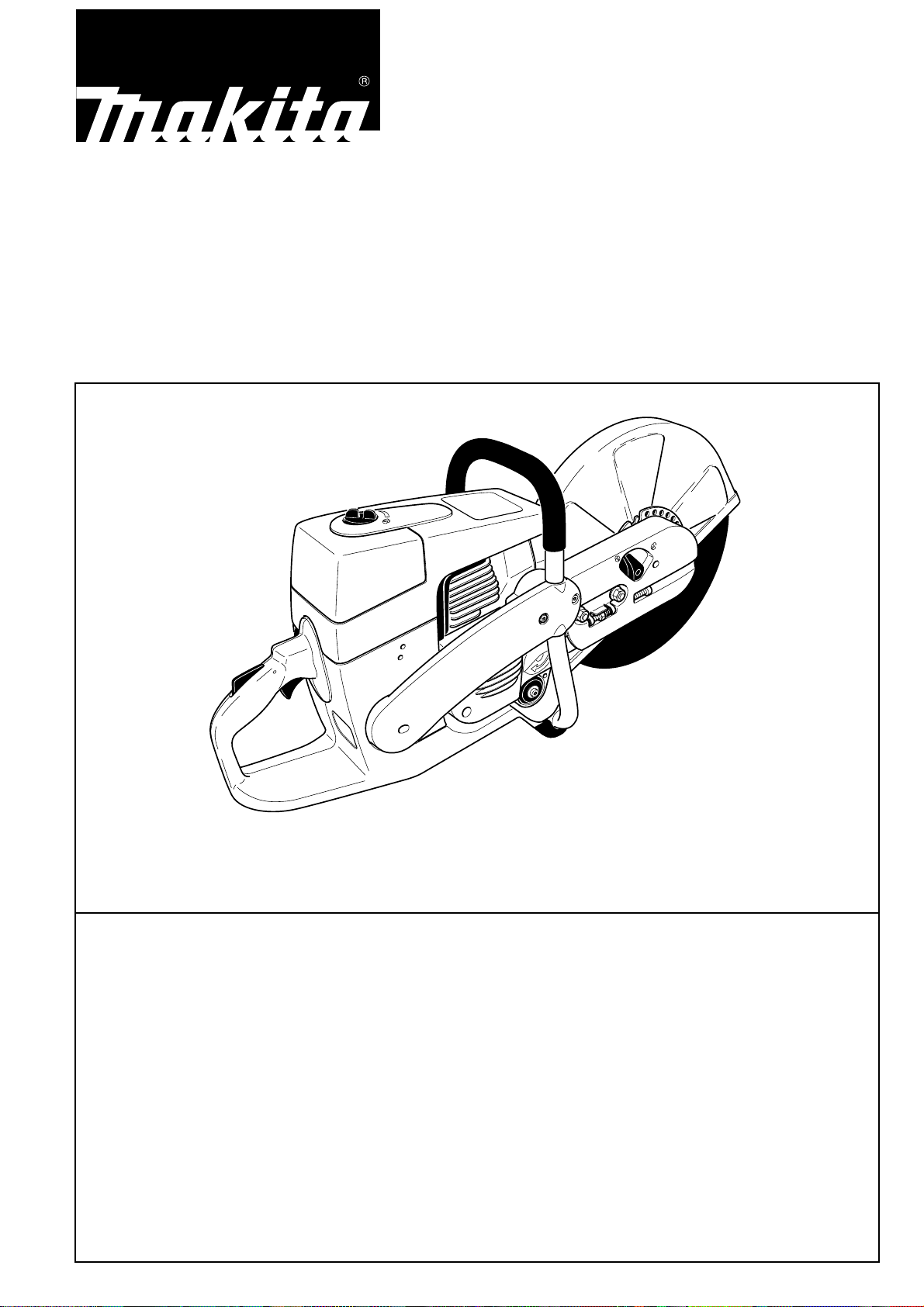
DPC 6400, DPC 6401
DPC 7300, DPC 7301
WARNING!
Read and understand this Manual. Always follow safety precautions in the Instruction and
Safety Manual. Improper use can cause serious injury!
The engine exhaust from this product contains chemicals known to the State of California to cause
cancer, birth defects or other reproductive harm. Preserve this Manual carefully!
ATTENTION!
Suivez toujours les conseils de sécurité du présent manuel d’instructions et de sécurité.
Une utilisation incorrecte de la découpeuse peut entraîner des blessures graves!
Conservez avec soin ce manuel! Les gaz d’échappement émis par ce produit contiennent des produits
chimiques connus par l’Etat de Californie pour provoquer le cancer, des défauts de naissance ou
autres dommages de reproduction. Lisez et comprenez ce manuel.
ADVERTENCIA:
Observe siempre las instrucciones de seguridad contenidas en el manual. Lea y compenétrese con el
contenido del manual. El uso inadecuado de la cortadora puede causar lesiones de gravedad.
Los gases de escape del motor de este producto contienen sustancias químicas conocidas en el Estado
de California como causantes de cáncer, defectos genéticos y otros problemas relacionados con la
reproducción. Conserve este manual cuidadosamente.
1
Page 2
Thank you for purchasing a MAKITA product!
Congratulations on choosing a MAKITA Power Cut cutoff saw!
Like our chain saws, the MAKITA Power Cuts feature specially
designed high-performance engines with outstanding
power-to-weight ratios, for heavy-duty yet lightweight tools.
Other advantages of the MAKITA Power Cuts:
• Sturdy construction and high reliability.
• Maintenance-free electronic ignition, hermetically sealed to
protect against dust and moisture.
• Vibration damping with the MAKITA 2-mass system (D2M)
for tireless working even when guiding the Power Cut by
hand.
• Five-stage air-filter system for reliable working even under
very dusty conditions.
• Two options for mounting the cutter attachment: Either
centrally, for good balance when guiding the unit manually,
or on the side, for flush cuts along walls or curbsides or
horizontally directly above the ground.
• Extensive line of synthetic-resin and diamond cutting discs,
and trolley with vibration damping, dust catcher, and several
systems for water supply to the cutting disc.
The following industrial property rights apply:
US 08510690, SE 95027298, SE 95027306, IT 95000653,
IT 95000654, GBM 9412558, GBM 9412559.
We want you to be satisfied with your MAKITA product.
In order to guarantee the optimal function and performance of
your Power Cut and to ensure your personal safety we would
request you to perform the following:
Read this Instruction and Safety manual carefully before
putting the Power Cut into operation for the first time,
and strictly observe the safety regulations! Failure to
observe these precautions can lead to severe injury or
death!
WARNING!
Some dust created by power sanding sawing,
grinding, drilling, and other construction activities
contains chemicals known (to the State of California)
to cause cancer, birth defects or other reproductive
harm.
Some examples of these chemicals are:
• lead from lead-based paints,
• crystalline silica from bricks and cement and
other masonry products, and
• arsenic and chromium from chemically-treated
lumber.
Y our risk from these exposures varies, depending on
how often you do this type of work.
To reduce your exposure to these chemicals: work in
a well ventilated area, and work with approved safety
equipment, such as those dust masks that are
specially designed to filter out microscopic particles.
Table of contents Page
Packing ................................................................................2
Delivery inventory ..............................................................3
Symbols ...............................................................................3
SAFETY PRECAUTIONS
General precautions........................................................4
Protective equipment .................................................. 4-5
Fuels / Refuelling ............................................................5
Putting into operation......................................................5
Cutting discs....................................................................6
Kickback and lock-in .......................................................7
Working behavior / Method of working ...........................7
Cutting metal ...................................................................8
Cutting masonry and concrete.................................... 8-9
Transport and storage ....................................................9
Maintenance..................................................................10
First aid .........................................................................10
Technical data...................................................................11
Denomination of components.........................................11
PUTTING INTO OPERATION
Mounting the cutting disc ..............................................12
Tightening the V-belt / Checking V-belt tension ...........13
Fuels / Refuelling .................................................... 13-14
Starting the engine.................................................. 14-15
Cold-starting..................................................................15
Warm-starting................................................................15
If the engine won’t start.................................................16
If the engine won’t start.................................................16
Working in winter ..........................................................16
Adjusting the carburetor .................................................17
MAINTENANCE
Changing the V-belt ......................................................1 8
Cleaning the protection hood........................................19
Cleaning / changing the air filter ............................. 19-20
Replacing the spark plug ..............................................20
Replacing the suction head ..........................................21
Replacing the starter cable ..................................... 21-22
Replacing the return spring ..........................................22
Instructions for periodic maintenance...........................26
Cutting attachment in central / side position.......... 23-24
Repositioning the cutting attachment ..................... 23-24
SPECIAL ACCESSORIES
Diamond cutting discs, cart, water tank
and pressure water system...........................................25
Service, spare parts and guarantee ......................... 26-27
Troubleshooting ...............................................................27
Extract from spare parts list............................................28
Accessories...................................................................28
Service stations ................................................................86
Packing
Your MAKITA Power Cut is packed in a cardboard box to
prevent shipping damage.
Cardboard is a basic raw material and is consequently reuseable or suitable for recycling (waste paper recycling).
RE Y
2
Page 3
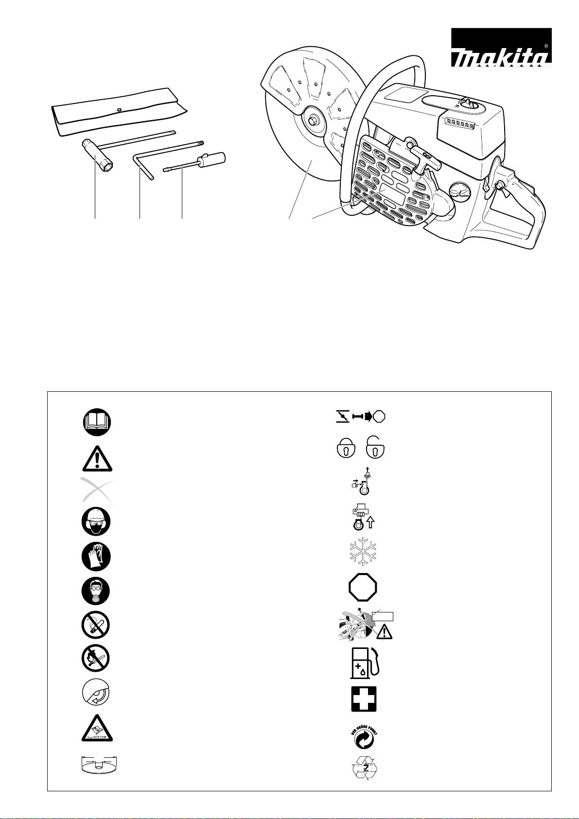
Delivery inventory
STOP
34521
1. Power Cut
2. Cutting disc
3. Universal wrench 13/19
4. Offset screwdriver
5. Screwdriver for carburetor adjustment
6. Instruction and Safety manual (not shown)
In case one of the parts listed should not be included in the
delivery inventory, please consult your sales agent.
Symbols
You will notice the following symbols on the Power Cut and in the Instruction Manual:
Read Instruction and Safety
Manual and follow the warningand safety precautions!
Particular care and caution!
2
1
Forbidden!
Wear protective helmet, eye and
ear protection!
Wear protective gloves!
Wear respiratory protection!
No smoking!
STOP
Combination Start/Stop (I/O)
switch, choke
Locked / Unlocked
Press starting valve
Engine - manual start
Working in winter
Stop engine!
Warning! Kickback!
No open fire!
Direction of cutting wheel
rotation
Warning: the max. peripheral
speed of the cutting disc
is 80 m/s!
Cutting disc dimensions
Fuel and oil mixture
First aid
Recycling
RE Y
3
Page 4
FE
A
B
C
D
SAFETY PRECAUTIONS
General precautions
- The operator MUST read this instruction manual to ensure
safe operation (even if you already have experience in
using cutoff saws). It is important to be familiar with the
operation of this particular cutoff saw. Users insufficiently
informed will endanger themselves as well as others due to
improper handling.
- Let only persons who have experience in using cutoff saws
work with this unit. When letting another person use the Power
Cut, this instruction manual must be provided along with it.
- First-time operators should ask a specialist to instruct them in
working with gasoline-powered cutoff saws.
- Children and persons under 18 years of age must not be
allowed to use this Power Cut. Persons over the age of 16
years may, however, use the Power Cut for the purpose of
being trained as long as they are under the supervision of a
qualified trainer.
- Working with the Power Cut requires high concentration.
- Operate the Power Cut only if you are in good physical
condition. If you are tired, your attention will be reduced. Be
especially careful at the end of a working day. Perform all work
calmly and carefully. The user has to accept liability for others.
- Never work while under the influence of alcohol, drugs, medication or other substances which may impair vision, dexterity
or judgement.
- A fire extinguisher must be available in the immediate vicinity
when working in easily inflammable vegetation or when it has
not rained for a long time (danger of fire).
- Asbestos and other materials that can release toxins may be
cut only with the necessary safety precautions and after
notification of the proper authorities and under their supervision or that of a person appointed by them.
1
2
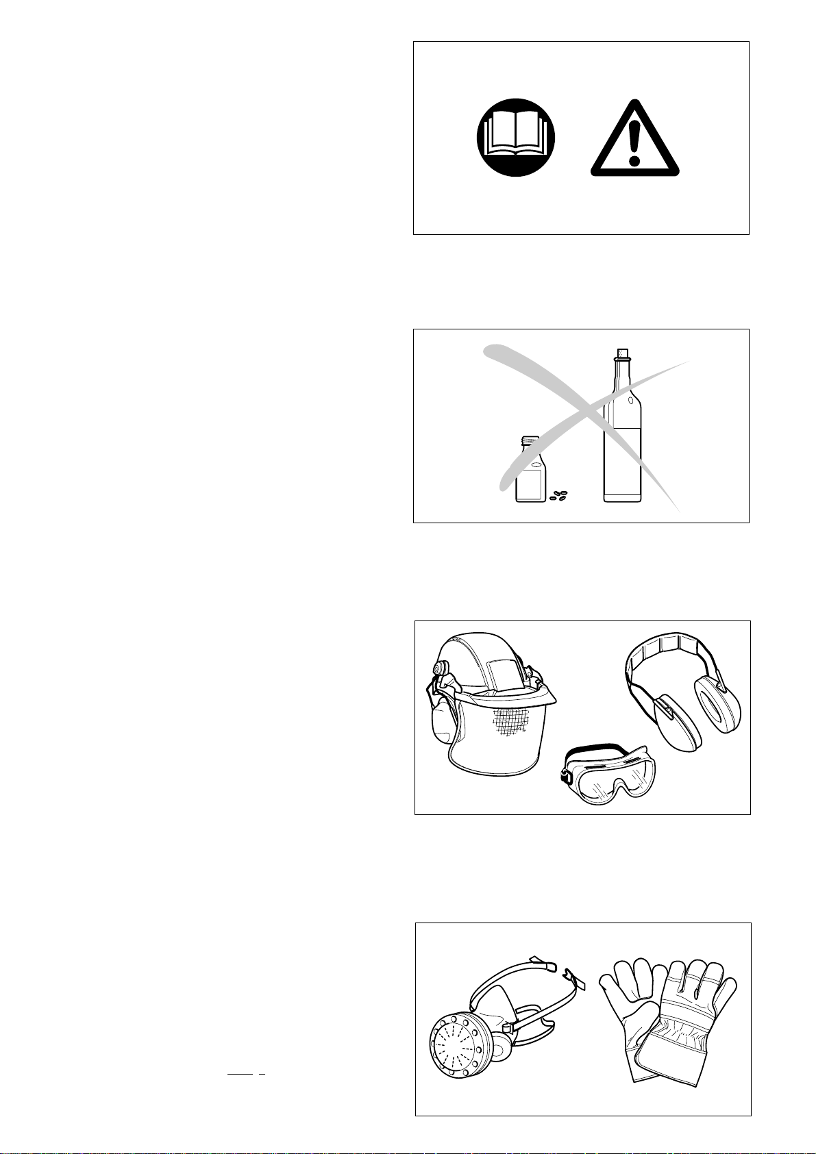
Protective equipment
- In order to avoid head, eye, hand or foot injuries as well as
to protect your hearing the following protective equipment must be used during operation of the Power Cut:
- The kind of clothing should be appropriate, i. e. it should be
tight-fitting but not be a hindrance. Clothing in which grains of
material can accumulate (trousers with cuffs, jackets and
trousers with wide-open pockets, etc.) must not be worn,
particularly when cutting metal.
- Do not wear any jewellery or clothing that can get caught or
distract from the operation of the Power Cut.
- It is necessary to wear a protective helmet whenever working
with the Power Cut. The protective helmet (A) is to be
checked in regular intervals for damage and is to be replaced
after 5 years at the latest. Use only approved protective
helmets.
- The helmet visor (B) protects the face from dust and material
grains. In order to prevent injuries to eyes and face, always
wear protective goggles (C) or visor when using the Power
Cut.
- To prevent hearing damage, always wear suitable personal
hearing protection. (ear muffs (D), ear plugs, etc.). Octave
brand analysis upon request.
- When dry-cutting dust-producing materials such as stone or
concrete, always wear approved respiratory protection (E).
- Work gloves (F) of tough leather are part of the required work
kit of the Power Cut and must
with the Power Cut.
always be worn when working
3
4
4
Page 5
H
G
- Always wear safety shoes or boots (G) with steel toes, non-skid
soles, and leg protectors when working with the Power Cut.
Safety shoes equipped with a protective layer provide protection
against cuts and ensure a secure footing.
- Always wear a work suit (H) of sturdy material.
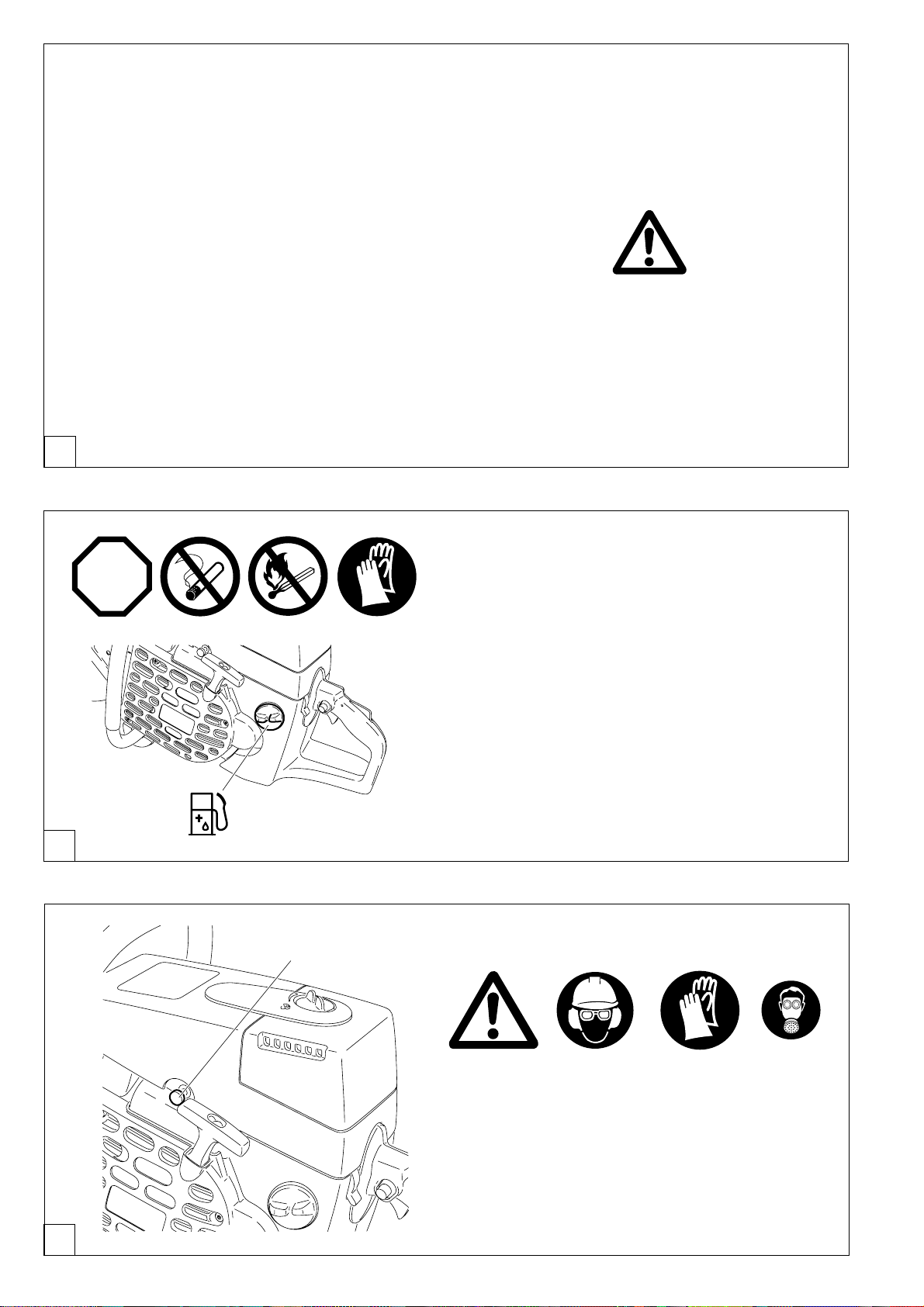
Fuels / Refuelling
- Go to a safe, level place before refuelling. Never refuel while
on scaffolding, on heaps of material, or in similar places!
- Switch off the engine before refuelling the Power Cut.
- Do not smoke or work near open fires (6).
- Let the engine cool down before refuelling.
- Fuels can contain substances similar to solvents. Eyes and skin
should not come in contact with mineral oil products. Always
wear protective gloves when refuelling (not the regular work
gloves!). Frequently clean and change protective clothes. Do
not breathe in fuel vapors. Inhalation of fuel vapours can be
hazardous to your health.
- Do not spill fuel. If a spill occurs, clean off the Power Cut
immediately. Fuel should not come in contact with clothes. If your
clothes have come in contact with fuel, change them at once.
- Ensure that no fuel is spilled into the soil (environmental
protection). Use an appropriate surface.
- Refuelling is not allowed in closed rooms. Fuel vapors will
accumulate near the floor (explosion hazard).
- Ensure to firmly tighten the screw cap of the fuel tank.
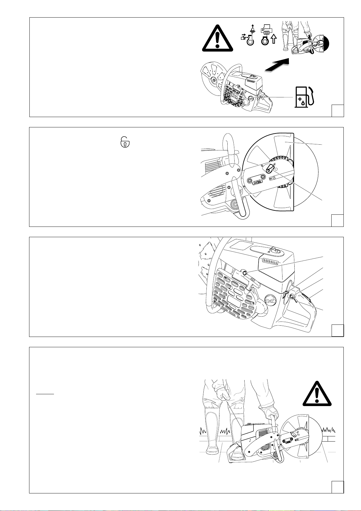
- Before starting the engine, move to a location at least 3 meters
(approx. 10 feet) from where you fuelled the Power Cut (7), but
not within the extended swing range of the cutting disc (direction
of sparks).
- Fuel cannot be stored for an unlimited period of time. Buy only
as much as will be consumed in the near future.
- When making up the gasoline/oil mixture, always put the oil in the
mixing container
- Use only approved and marked containers for the transport and
storage of fuel.
- Keep fuel away from children!
first, and then the gasoline.
5
6
3 meters
(10 feet)
Putting into operation
- Do not work on your own. There must be someone around
in case of an emergency (within shouting distance).
- Observe all anti-noise regulations when working in residential
areas.
- Never use the Power Cut near inflammable materials or
explosive gases! The Power Cut can create sparks leading
to fire or explosion!
- Make sure that all persons within 30 meters (100 feet), such as
other workers, are wearing protective gear (see "Protective
Equipment") (8). Children and other unauthorized persons must
remain more than 30 meters (100 feet) away from the working
area. Keep an eye out for animals as well (9).
- Before starting work the Power Cut must be checked for
perfect function and operating safety according to the
prescriptions.
In particular, make sure that the cutting wheel is in good
condition(replace immediately if torn, damaged or bent), the
cutting wheel is properly mounted, the protective hood is locked
in place, the hand guard is properly mounted, the V-belt has the
proper tension, the throttle moves easily and the half-throttle
lock button functions properly, the grips are clean and dry, and
the combination switch functions properly.
- Start the Power Cut only after complete assembly and inspection. Never use the Power Cut when it is not completely
assembled.
7
30 m (100 feet)
8
9
= wearing Protective Equipment
5
Page 6
Cutoff discs
- The protection hood must always be on! Change discs only
with the engine off!
- There are two basic types of cutoff discs:
- For metal (hot cutting)
- For masonry (cold cutting)
NOTE:
When using diamond cutoff discs, always make sure to observe the
"direction of rotation" markings. Diamond discs should only be
used for cutting masonry/brick/ concrete etc.
- Cutoff discs are intended only for radial loading, i.e. for cutting.
Do not grind with the sides of the cutting disk! This will break the
disk! (10)!
Caution!
Never change direction (turning radius less than 5 meters /
16 feet), exert lateral (sideways) pressure, or tip the Power Cut
during cutting (11)!
- Use a cutting disc only for cutting the materials it is intended for.
The proper type of disc must be used, for either metals or
masonry.
- The arbour hole (bore) of the cutting disc must fit the shaft
exactly. If the arbour hole is larger than the shaft diameter, a
spacer ring must be used.
- Use only cutting wheels approved by the DSA (German Abrasive Disc Committee) or equivalent organisation for freehand
cutting at up to 4370 RPM (= 80 m/sec. at circumference) for
14"/350 mm discs, or up to 5100 RPM (= 80 m/sec. at circumference) for 12"/300 mm discs.
- The disc must be free of defects (12). Do not use defective
cutting discs.
Always tighten the cutting disc mounting bolt to a torque of 30
Nm. Otherwise, the cutting disc can twist.
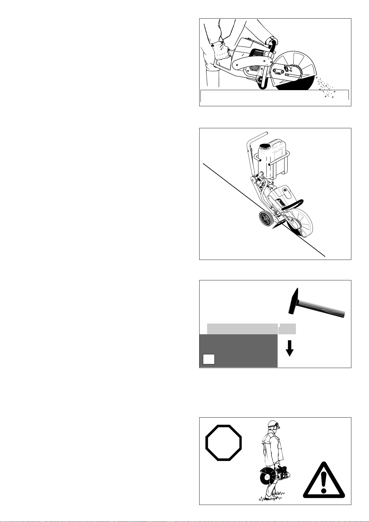
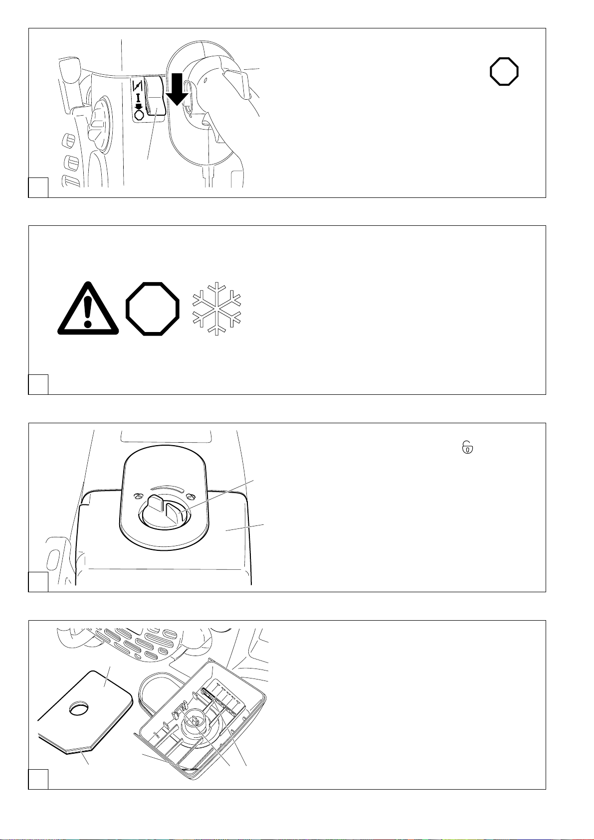
- Before starting the cutting disc, make sure you have a steady
footing.
- Put the Power Cut into operation only as described in this
instruction manual (13). Always place your left foot in the rear
handle and grasp the other handle firmly (with thumb and
fingers). Other starting methods are not allowed.
- When starting the Power Cut it must be well supported and
securely held. The cutting disc must not be touching anything.
- If the cutting disc is new, test it by running it at least 60 seconds
at top speed. When doing this, make sure that no persons or
body parts are in the extended swing range of the disc, in case
it is defective and flies apart.
- When working with the Power Cut always hold it with both
hands. Take the back handle with the right hand and the tubular
handle with the left hand. Hold the handles tightly with your
thumbs facing your fingers.
- CAUTION: When you release the throttle lever the disc will
keep spinning for a short period of time (free-wheeling
effect).
- Continuously ensure that you have a safe footing.
- Hold the Power Cut such that you will not breathe in the exhaust
gas. Do not work in closed rooms or in deep holes or ditches
(danger of poisoning by fumes).
- Switch off the Power Cut immediately if you observe any
changes in its operating behavior.
- Switch off the engine before inspecting the V-belt tension
or tightening it, replacing the cutting wheel, repositioning
the cutter attachment (side or middle position) or eliminating
faults (14).
- Turn off the engine immediately and check the disc if you hear
or feel any change in cutting behaviour.
- Turn off the Power Cut when taking a break or stopping work
(14). Place the unit in such a way that the disc is not touching
anything and cannot endanger anyone.
- Do not put the overheated Power Cut in dry grass or on any
inflammable objects. The muffler is very hot (danger of fire).
- IMPORTANT: After wet cutting, first turn off the water feed and
then let the disc run at least 30 seconds, to fling off the remaining
water and prevent corrosion.
13
14
10
11
12
min. 5 m
(16 feet)
P
O
T
S
● Maintenance
● Refuelling
● Changing cutoff discs
● Repositioning the
cutting attachment
● Stopping work
● Transport
● Putting out of function
6
Page 7
Kickback and lock-in
- When working with the Power Cut there is a danger of kickback
and lock-in.
- Kickback occurs when the top of the cutting disc is used for
cutting (15).
- This causes the Power Cut to be thrown back toward the user
with great force and out of control. Risk of injury!
To prevent kickback, observe the following:
- Never cut with the section of the cutting disc shown in figure 15.
Be especially careful when reinserting the disc into cuts
that have already been started!
- Lock-in occurs when the cut narrows (crack, or workpiece under
stress).
- This causes the Power Cut to suddenly jump forward, out of
control and with great force. Risk of injury!
To prevent lock-in, observe the following:
- When reinserting the disc into previous cuts, have the Power
Cut running at top speed. Always cut at top speed.
- Always support the workpiece so that the cut is under tension
(16), so that the cut does not press together and jam the cutting
disc as it proceeds through the material.
- When starting a cut, apply the disc to the workpiece with care.
Do not just shove it into the material.
- Never cut more than one piece at a time! When cutting, make
sure that no other workpiece comes into contact.
15
Working behavior / Method of working
- Before starting work, check the work area for any hazards
(electrical wires, inflammable substances). Clearly mark the
work area (for example with warning signs or by cordoning off
the area).
- When working with the Power Cut hold it firmly by the front and
rear handles. Never leave the Power Cut unattended!
- Whenever possible run the Power Cut at the rated arbour
speed (see ”Technical Data”).
- Only use the Power Cut during good light and visibility periods.
Be aware of slippery or wet areas, and of ice and snow (risk of
slipping).
- Never work on unstable surfaces. Make sure that there are no
obstacles in the working area, risk of stumbling. Always ensure
that you have a safe footing.
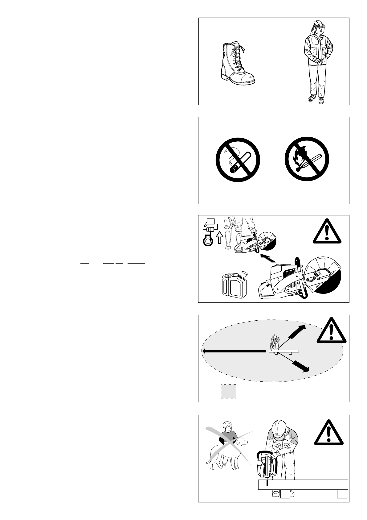
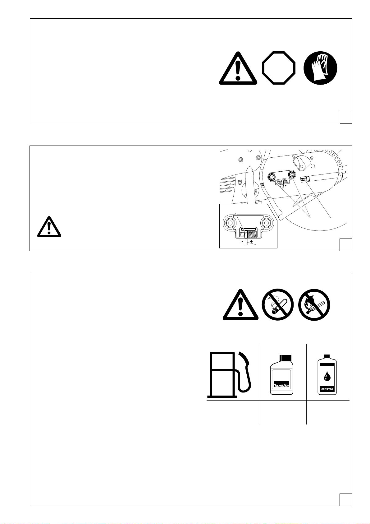
- Never cut above your shoulder height (17).
- Never stand on a ladder to cut (17).
- Never use the Power Cut while standing on scaffolding.
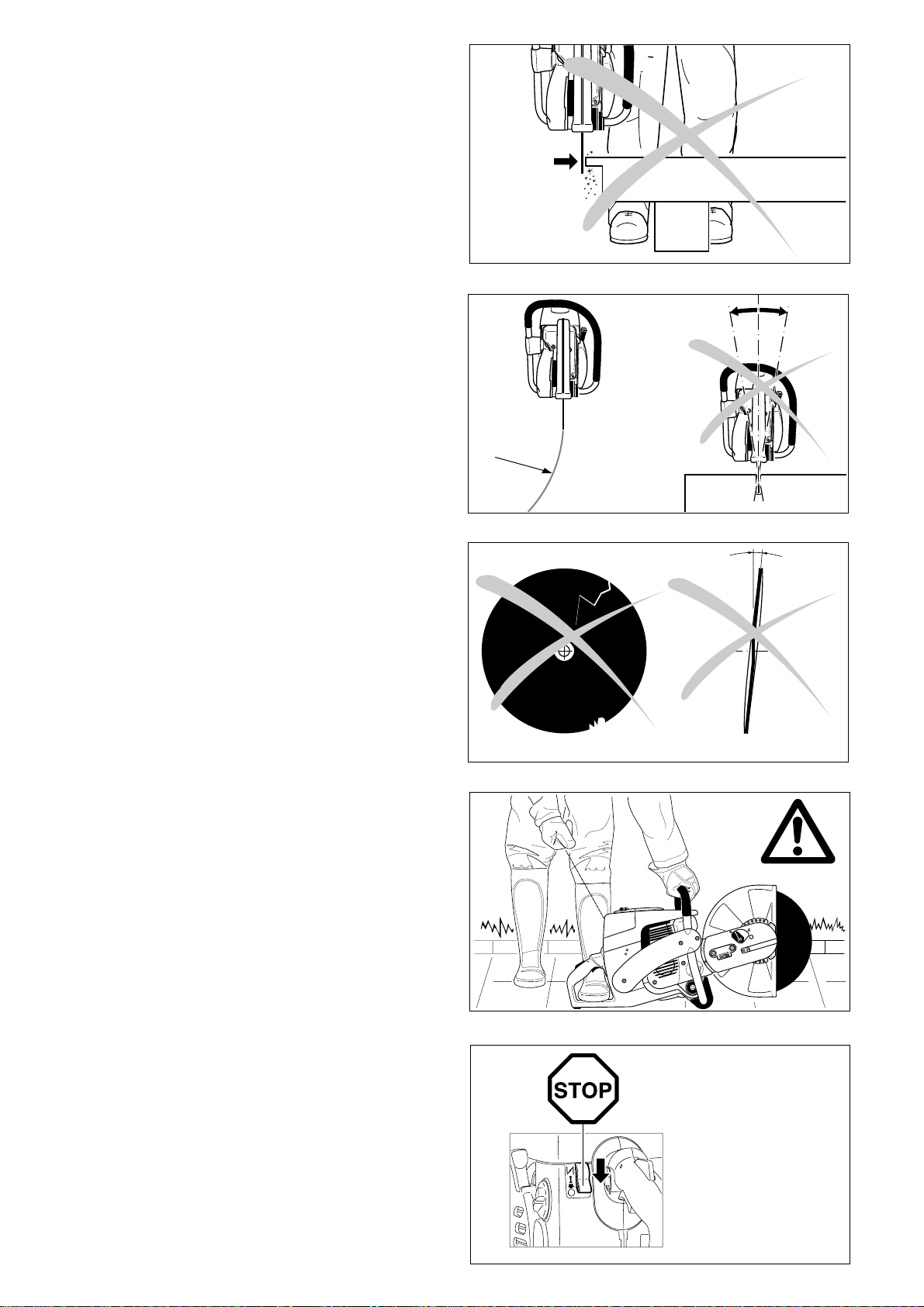
- Do not lean over too far when working. When putting down and
picking up the Power Cut, do not bend over from the waist, but
instead bend in the knees. Save your back!
- Guide the Power Cut in such a way that no part of your body is
within the extended swing range of the disc (18).
- Use cutting discs only for the materials for which they are
designed!
- Use cutting discs only for the materials for which they are
designed. Do not use the Power Cut to lift up and shovel away
pieces of material and other objects.
Important! Before cutting, remove all foreign objects, such as
rocks, gravel, nails etc. from the cutting area. Otherwise, such
objects can be flung away by the disc with great speed. Injury
hazard!
- When cutting workpieces down to length use a firm support. If
necessary, secure the workpiece from slipping, but do not
steady it with your foot or allow another person to hold it.
- When cutting round items, always secure them against rotation.
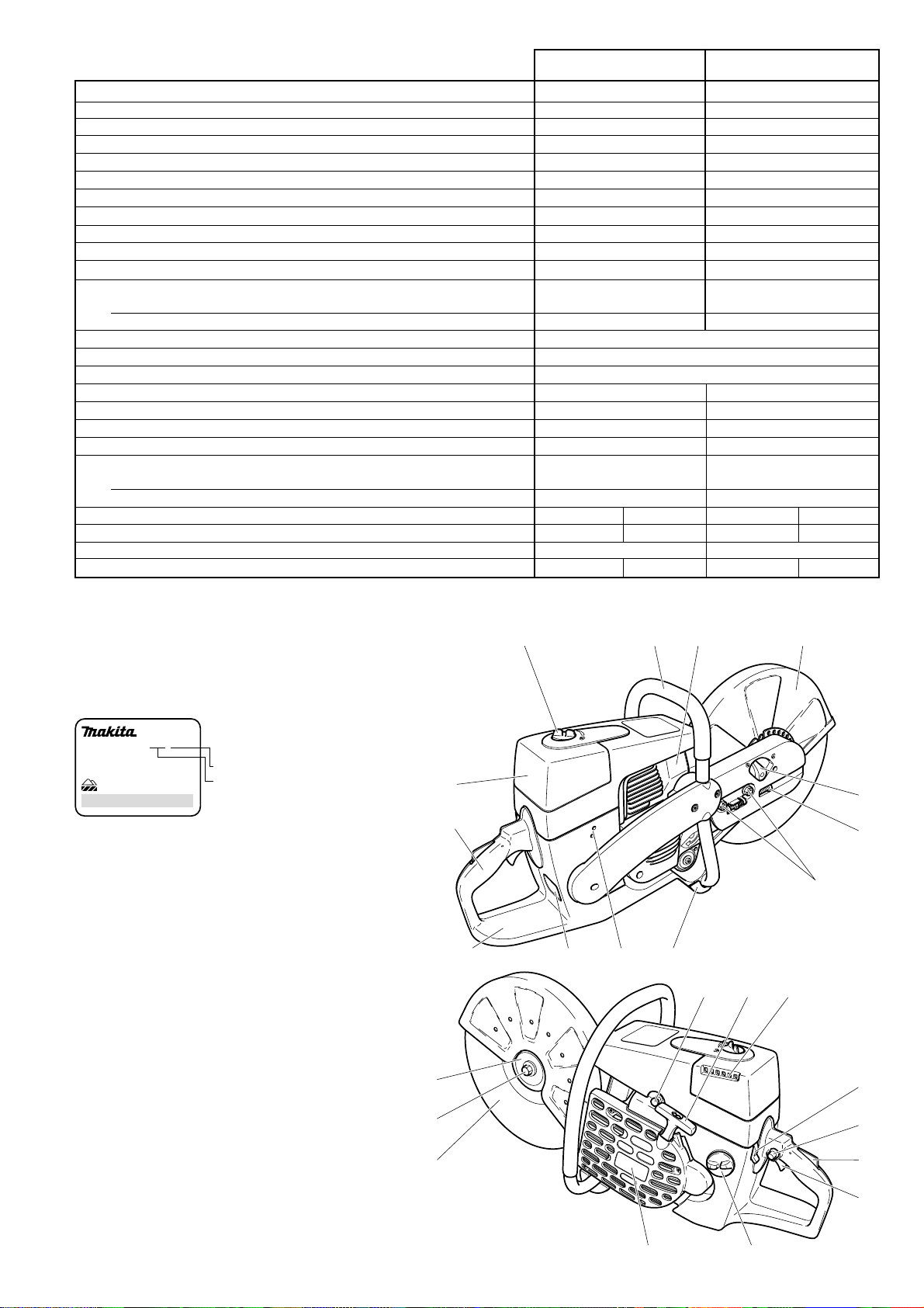
- When guiding the Power Cut by hand, use the side mounting
position of the cutter attachment only when actually necessary.
Otherwise, always use the central position. This gives the unit
a better balance, for reduced operator fatigue.
16
17
18
7
Page 8
Cutting metals
IMPORTANT!
Always wear approved respiratory protection!
Materials that can release toxic substances may be cut only
after notifying the proper authorities and under their supervision or that of a person appointed by them.
CAUTION!
The rapid rotation of the cutting disc heats metal and melts it
at the point of contact. Swing the guard as far down as
possible behind the cut (19) in order to direct the stream of
sparks forward, away from the operator (fire hazard).
- Determine the direction of cutting, mark the cut and apply the
disc to the material at moderate speed, to cut a guide groove
before going to top speed and applying more pressure to the
Power Cut.
- Keep the disc straight and vertical. Do not tip it, as this can break
it.
- The best way to get a good, clean cut is to pull or move the
Power Cut back and forth. Do not simply press the disc into the
material.
- Thick round stock is best cut in stages (20).
- Thin tubing and pipes can be cut with a simple downward cut.
- Cut large-diameter pipes as for round stock. To prevent tipping
and for better control, do not let the disc sink too deeply into the
material. Instead, always cut shallow around the whole piece.
- Worn discs have a smaller diameter than new discs, so that at
the same engine speed they have a lower effective circumferential speed and therefore do not cut as well.
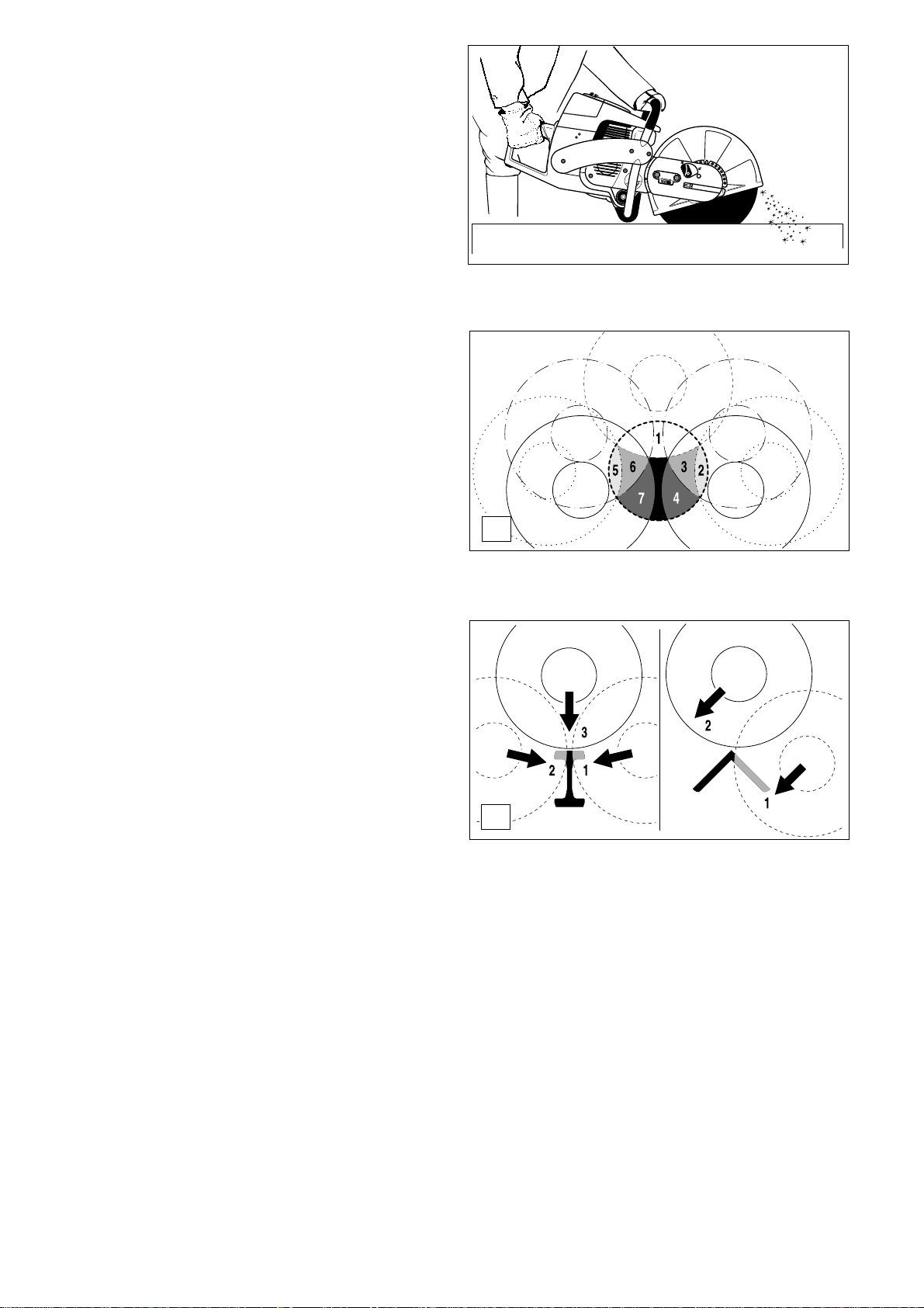
- Cut I-beams and L-bars in steps; see Figure 21.
- Cut bands and plates like pipes: along the wide side with a long
cut.
- When cutting material under stress (supported material or
material in structures), always make a notch in the thrust
(pressure) side, and then cut from the tension side, so that the
disc does not lock in. Secure cutoff material from falling!
CAUTION!
If there is a chance that the material is under stress, be
prepared for it to kick back. Make sure you can get out of the
way if you have to!
Be particularly careful in scrap-metal yards, junkyards, at
accident sites, and with haphazard piles of material. Precariously balanced pieces or pieces under stress can act in
unpredictable ways, and may slide, jump out, or burst. Secure cutoff material from falling! Always exercise extreme
caution and use only equipment that is in perfect working
order.
Observe the accident-prevention rules and regulations of
your employer and/or insurance organization.
19
20
21
Cutting masonry and concrete
IMPORTANT!
Always wear approved respiratory protection!
Asbestos and other materials that can release toxic sub-
stances may be cut only after notifying the proper authorities
and under their supervision or that of a person appointed by
them. When cutting prestressed and reinforced concrete
piles, follow the instructions and standards of the responsible authorities or the builder of the structural member.
Reinforcement rods must be cut in the prescribed sequence
and in accordance with applicable safety regulations.
NOTE:
Mortar, stone, and concrete develop large quantities of dust
during cutting. To increase the lifetime of the cutting disc (by
cooling), to improve visibility, and to avoid excessive dust creation, we strongly recommend wet cutting instead of dry cutting.
8
Page 9
In wet cutting, the disc is wetted at an equal rate on both sides by
a trickle of water. MAKITA offers the right accessories for all wet
cutting applications (see also "SPECIAL ACCESSORIES").
- Remove foreign objects such as sand, stones and nails found
within the working area. Caution: Watch out for electric
wires and cables!
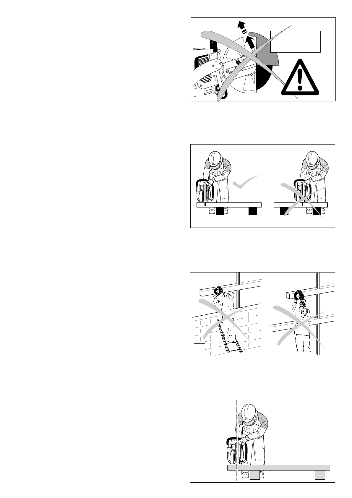
The rapid rotation of the cutting disc at the point of contact
throws fragments out of the cut groove at high speed. For
your safety, swing the protection hood down as far as
possible behind the cut (23), so that material fragments are
thrown forward, away from the operator.
- Mark the cut, and then make a groove about 5 mm (just under
1/5") along the entire length of the planned cut. This groove
will then guide the Power Cut accurately guring the actual
cutoff.
NOTE:
For long, straight cuts we recommend using a cart (24, see also
"SPECIAL ACCESSORIES"). This makes it much easier to guide
the unit straight.
- Perform the cut with a steady back-and-forth motion.
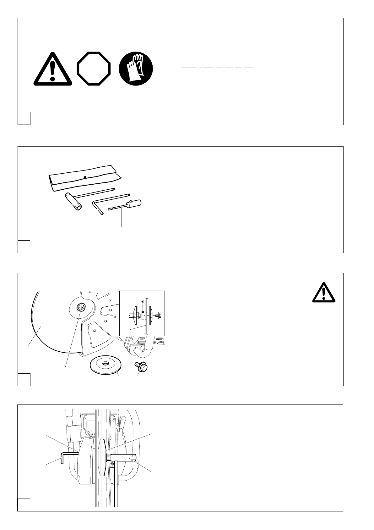
- When cutting slabs to size, you need not cut through the entire
material thickness (creating unnecessary dust). Instead, simply make a shallow groove, and then knock off the excess
material cleanly on a flat surface (25).
CAREFUL!
When cutting into lengths, cutting through material, making
cutouts, etc., always make sure to plan the direction and sequence of cuts in such a way that the disc does not get jammed
by the cut-off piece, and that no persons can be injured by falling
pieces.
23
Transport and storage
- Always turn off the Power Cut when transporting it or
moving it from place to place on a site (26).
- Never carry or move the unit with the engine on or the disc
moving!
- Carry the unit only by the tubular (middle) handle with the
cutting disc pointing behind you (26). Avoid touching the
exhaust muffler (burn hazard!)
- When moving the Power Cut over longer distances, use a
wheelbarrow or wagon.
- When transporting the Power Cut in a vehicle, make sure it is
securely positioned in such a way that no fuel can leak out.
Always remove the cutting disc before transporting the unit in
a vehicle.
- The Power Cut should be stored safely in a dry place. It must
not be left outdoors! Always dismount the cutting disc before
storage. Keep the Power Cut away from children.
- Before long-term storage and before shipping the Power
Cut, follow the instructions in the chapter on "Periodic
care and maintenance". ALWAYS empty the fuel tank and
run the carburetor dry.
- When putting cutting discs in storage, be careful to:
- Clean and dry them well.
- Store them lying down flat.
- Avoid dampness, freezing temperatures, direct sunshine,
high temperatures and temperature fluctuations, as these can
cause breakage and splintering.
- Always check new cutting discs or cutting discs that have
been in storage to make sure that they are free of defects.
24
25
STOP
26
9
Page 10

Maintenance
STOP
- Before performing maintenance work switch off the Power
Cut (27) and pull out the plug cap.
- Always check the Power Cut before using it to make sure that
it is in good working order. In particular, make sure that the
cutting disc is properly mounted. Make sure that the cutting
wheel is undamaged and suitable for the job it will be used for.
- Operate the Power Cut only at a low noise and emission level.
For this ensure the carburetor is adjusted correctly.
- Clean the Power Cut regularly.
- Check the fuel tank cap regularly for good sealing.
Observe the accident prevention instructions issued by
trade associations and insurance companies. NEVER make
any modifications to the Power Cut! You will only be
putting your own safety at risk!
Perform only the maintenance and repair works described in
the instruction manual. All other work must be carried out by
MAKITA Service.
Use only original MAKITA spares and accessories.
The use of non-MAKITA spares, accessories, or cutting discs
increases the risk of accident. We cannot accept any responsibility for accidents or damage occurring in association with
the use of cutting discs or accessories other than original
MAKITA.
27
SERVICE
28
First aid
For the event of a possible accident, please make sure that a
first aid kit is always immediately available close by. Immediately replace any items used from the first aid box.
When calling for help, give the following information:
- Place of the accident
- What happened
- Number of injured people
- Kind of injuries
- Your name!
NOTE
Individuals with poor circulation who are exposed to excessive
vibration may experience injury to blood vessels or the nervous
system.
Vibration may cause the following symptoms to occur in the
fingers, hands or wrists: ”Falling asleep” (numbness), tingling,
pain, stabbing sensation, alteration of skin colour or of the skin.
If any of these symptoms occur, see a physician!
29
10
Page 11
Technical data
DPC 6400 DPC6401 DPC 7300 DPC 7301
Displacement cu in (cm3) 3,9 (64) 4,5 (73)
Bore in (mm) 1,85 (47) 1,97 (50)
Stroke in (mm) 1,46 (37) 1,46 (37)
Max. power hp (kW) 4,3 (3,2) 5,6 (4,2)
Max. torque Nm 4,0 5,0
Idling speed rpm 2.500 2.500
Clutch engagement speed rpm 3.800 3.800
Engine speed limitation rpm 9.350 9.350
Max. spindle speed rpm 4.300 4.300
Sound pressure level at the operators ear
1)
dB (A) 97 104
Sound pressure level at the bystander’s position (50 ft)1)dB (A) 84 86
Vibration acceleration a
- Tubular handle (idle/rated spindle speed) m/s
- Rear handle (idle/rated spindle speed) m/s
per EN 1454
h,w
2
2
6 / 5 7 / 6
8 / 6 8 / 7
Carburetor (diaphragm carburetor) Type TILLOTSON HS-273 A
Ignition system (with speed limitation) Type electronic
Spark plug Type
NGK BPMR 7A / BOSCH WSR 6F / CHAMPION RCJ 6Y
Electrode gap in (mm) .020 (0,5) .020 (0,5)
Fuel consumption at max. load per ISO 8893 kg/h 1,65 2,1
Specific consumption at max. load per ISO 8893 g/kWh 500 500
Fuel tank capacity fl oz (l) 37 (1,1) 37 (1,1)
Mixture ratio (fuel/two-stroke oil)
- when using MAKITA HP 100 high-performance oil 100:1 100:1
- when using MAKITA oil 50:1 50:1
Cutting disc for 80 m/sec.
2) 3)
(DSA approved) dimensions: in (mm)
12” / 20mm / 0,2”
14” / 20 mm / 0,2” 12” / 20mm / 0,2”
14” / 20 mm / 0,2”
Arbor diameter in (mm) 20 mm 20 mm 20 mm 20 mm
V-belt part no. 965 300 470 965 300 470
Overall weight (tanks empty, without cutting disc ) lb 21.38 21.82 21.60 22.04
1)
According to UL-test requirement under full load (cutting concrete).
2)
Circumference speed at max. engine speed
3)
Outside diameter / arbor hole / thickness
Denomination of components
DPC 7301
EMI OFB
973108
22045 Hamburg, Germany
0201 123456
394.100.661 Typ 394
1 Handle
2 Filter cover for air filter and spark plug cap
3 Cover lock
4 Tubular handle
5 Muffler with spark arrester screen
6 Protection hood
7 Hood lock
8 V-belt tension adjusting screw
9 Retaining nuts
10 Base
11 Carburetor adjustment opening
12 Identification plate
13 Fuel tank with handle
14 Starting valve
15 Starter grip
16 Air intake
17 Combination Start/Stop (I/O) switch, choke
18 Stop knob for halfway throttle
19 Safety locking button
20 Throttle lever
21 Fuel tank cap
22 Fan housing with starting assembly
23 Cutting disc
24 Disc bolt
25 Spring washer
Identification plate (12)
Indicate when ordering spare parts!
Serial number
Year of manufacture
25
24
23
3 4 5 6
2
1
7
8
9
12 1113
10
14 15 16
17
18
19
20
2122
11
Page 12
A
STOP
PUTTING INTO OPERATION
CAUTION:
Always turn off the engine and pull off the spark plug cap
before doing any work on the Power Cut! Always wear
protective gloves!
CAUTION:
Start the Power Cut only after complete assembly and
inspection.
For the the following work, use the assembly tools included
with delivery:
1. 13/19 AF combination wrench
2. Allen key
3. Carburetor adjustment screwdriver
B
C
Place the Power Cut on a stable surface and carry out the
1
2
3
Schematic drawing
7
5
5
following assembly steps:
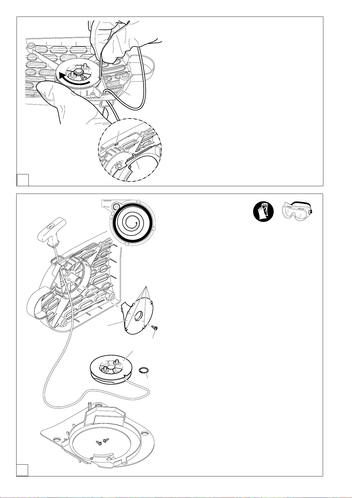
Mounting the cutting disc
Inspect the disc for damage.
See SAFETY INSTRUCTIONS, Page 6.
Unscrew screw (9) and remove the spring washer (8).
Before assembly make sure the tool area and contact
surfaces are absolutely clean.
Place the cutting disc (5) on the arbour (7).
For cutting discs with 1" arbour hole use the optional accessory
adapter ring (*), part number 394 228 120.
CAUTION: When using a diamond cutting disc be sure
7
98
to mount it so that it rotates in the proper direction!
12
D
10
Place the spring washer (8) on the arbour and insert the screw
8
2
(C/9) and tighten by hand.
Slowly turn the cutting disc until the stop hole of the V-belt
wheel is visible in the drive-arm hole (10).
Insert the Allen key (2) as far as it will go. The shaft is now
blocked.
Tighten the screw with the combination wrench (1)
1
NOTE: Tighten the screw firmly (30 ± 2 Nm), as otherwise the
cutting wheel may slip during cutting.
Page 13
Tightening the V-belt /
Checking V-belt tension
IMPORTANT
Exact V-belt tension is essential for maximum cutting
performance with minimum fuel consumption. Improper
V-belt tension will result in premature wear to the V-belt
and V-belt wheel or damage to the clutch bearing.
NOTE: The two fastening nuts (11) must be loosened before
tightening the V-belt or checking the tension.
To increase the belt tension, turn the tightening screw (12) to
the right (clockwise) with the combination wrench included
with the Power Cut.
The belt tension is correctly adjusted when the nut (13) is
centred on the mark (14).
:
IMPORTANT:
After tightening/inspection, make certain to tighten
the fastening nuts (11) (30 ± 2 Nm).
13
STOP
14
E
11 12
F
Fuels
Caution:
The Power Cut uses mineral-oil products (gasoline and
oil).
Be especially careful when handling gasoline.
Do not smoke. Do not allow gasoline to come near flames,
sparks or fire (explosion hazard).
Fuel mixture
The Power Cut is powered by a high-performance two-stroke
engine. It runs on a mixture of gasoline and two-stroke engine
oil.
The engine is designed for unleaded regular gasoline with a min.
octane value of 91 ROZ. In case no such fuel is available, you
can use fuel with a higher octane value. This will not affect the
engine.
In order to obtain an optimum engine output and to protect
your health and the environment use unleaded fuel only.
Gasoline which contens alcohol should not used in
MAKITA products.
To lubricate the engine, use a two-stroke engine oil (quality
grade TC-3), which is added to the fuel. The engine is designed
for the use of MAKITA HP 100 high-performance two-stroke
engine oil at a mixture ratio of only 100:1 to protect the environment. In addition, this ensures a long service life and reliable
operation with minimum exhaust emissions.
Gasoline
+
1.0 Us-gal. (3.7 l) 1.25 floz. (37 cm3) 2.6 floz. (75 cm3)
2.5 Us-gal. (9.4 l) 3.2 floz. (94 cm3) 6.4 floz. (189 cm3)
5.0 Us-gal. (18.9 l) 6.4 floz. (189 cm3) 12.8 floz. (378 cm3)
The correct mixture ratio:
100:1 When using MAKITA HP 100 high-performance
two-stroke engine oil, i. e. 100 parts gasoline to
1 part oil.
50:1 When using MAKITA high-performance two-
stroke engine oil, i. e. 50 parts gasoline to 1
part oil.
100:1
HP 100
50:1
OIL
50:1
G
13
Page 14
MAKITA HP 100 high-performance two-stroke engine oil is
available in the following sizes to suit your individual requirements:
0,5 l Best.-Nr. 980 008 609
MAKITA high-performance two-stroke engine oil (50:1) is
available in the following sizes to suit your individual requirements:
1 l Best.-Nr. 980 008 607
100 ml Best.-Nr. 980 008 606
NOTE: For preparing the fuel-oil mixture first mix the entire oil
quantity with half of the fuel required, then add the remaining
fuel. Shake the finished mixture thoroughly before pouring it
into the Power Cut tank.
Caution: Open the tank cap carefully, as pressure might
have built up inside!
It is not wise to add more engine oil than specified to
ensure safe operation. This will only result in a higher
production of combus-tion residues which will pollute
the environment and clog the exhaust channel in the
cylinder as well as the muffler. In addition, fuel consump-
A
tion will rise and performance will decrease.
Fuel storage
Fuels have only a limited shelf-life. Buy only as much as you
will use in 4 weeks.
Store fuel only in approved and marked containers.
AVOID SKIN AND EYE CONTACT
Mineral oil products degrease your skin. If your skin comes in
contact with these substances repeatedly and for an extended period of time, it will desiccate. Various skin deseases
may result. In addition, allergic reactions are known to occur.
Eyes can be irritated by contact with oil. If oil comes into your
eyes, immediately wash them with clear water.
If your eyes are still irritated, see a doctor immediately!
B
STOP
Refuelling
IMPORTANT:
FOLLOW THE SAFETY PRECAUTIONS!
Be careful and cautious when handling fuels.
The engine must be turned off and cooled down!
Carefully clean the area around the fuel-tank filler neck to
keep dirt from getting in the tank.
Place the unit on its side on an even surface.
Unscrew the tank cap and fill tank with fuel mixture. Take care
to avoid spilling.
Tightly screw on the cap.
Clean screw cap and tank after refuelling. Never start or
operate the Power Cut in the same place as it was fuelled!
Fuel mixture
Starting the engine
1
if
14
necessary
This model features a semiautomatic starting valve (1) to make
starting easier. Pushing this valve in reduces the amount of
compression effort needed, so that it is easier to bring the engine
up to starting speed when pulling the starter cable.
The high pressure increase in the combustion chamber that
results from the first ignitions will automatically close the
starting valve (button pops back out).
C
Page 15
CAUTION:
5
4
6
7
8
Observe the SAFETY INSTRUCTIONS on page 5!
Start the Power Cut only after complete assembly and
inspection!
Move at least 3m (10 feet) away from the place where you
fuelled the Power Cut.
Make sure you have a good footing, and place the Power
Cut on the ground in such a way that the cutting disc is not
touching anything.
2
1
3 meters
(10 feet)
D
Turn the hood lock (2) to position and hold it there.
Pivot the hood (3) back as far as it will go.
Release the hood lock and pivot the hood lightly back and forth
until the lock engages.
Cold-starting
Move the combination switch (5) up (choke position).
Grasp handle (hand pressure actuates the grip throttle
lever lock (7)).
Push the throttle (8) in all the way and hold it.
Press the throttle lock (6) and release the throttle (8) (the
throttle lock will hold the throttle at half-throttle position).
NOTE: If the Power Cut is installed in the trolley, the control
lever should be in the second arrest position.
Push the starting valve (4).
3
2
E
Grasp the tubular handle firmly with one hand and press the
Power Cut against the ground.
Place the tip of your left foot in the rear handle.
Pull the starter cable strong and rapidly until you hear the first
audible ignition.
CAUTION: Do not pull out the starter cable more than approx.
50 cm (20"), and lead it back by hand.
Press in the starting valve (F/4) again.
Put the combination switch (F/5) in position “I”.
Keep pulling the starter cable until the engine catches.
As soon as the engine is running, press the throttle (F/8) to
release the half-throttle lock (F/6), allowing the engine to idle.
Warm-starting
As described under ”Cold starting”, except without putting the
combination switch (F/5) in choke position.
F
G
15
Page 16
A
P
O
ST
1
STOP
Stopping the engine
Push the combination switch (1) down to position .
STOP
Working in winter
In conditions of low temperatures and high humidity the
carburetor can ice up. To prevent this, at temperatures below
0° C / 32° F hot air from the cylinder chamber can be inducted.
This also brings the engine to operating temperature faster.
At temperatures above freezing the carburetor must NOT
be fed heated air.
Failure to follow these instructions can lead to damage to
the cylinder and piston!
B
C
Turn the cover lock (2) to the ”unlocked ” position and
carefully remove the filter cover (3).
2
3
Take the filter element (4) out of the filter cover.
4
Take the summer-winter insert out of the summer position (7)
and press it in as illustrated in the winter position (8)
16
D
NOTE: At temperatures over 0° C / 32° F the summer-winter
insert should always be placed in the summer position (7).
NOTE: When placing the filter element (4) in the filter cover,
position it with the angled corner (5) against the angled corner
in the inside of the cover.
6
5
87
Page 17
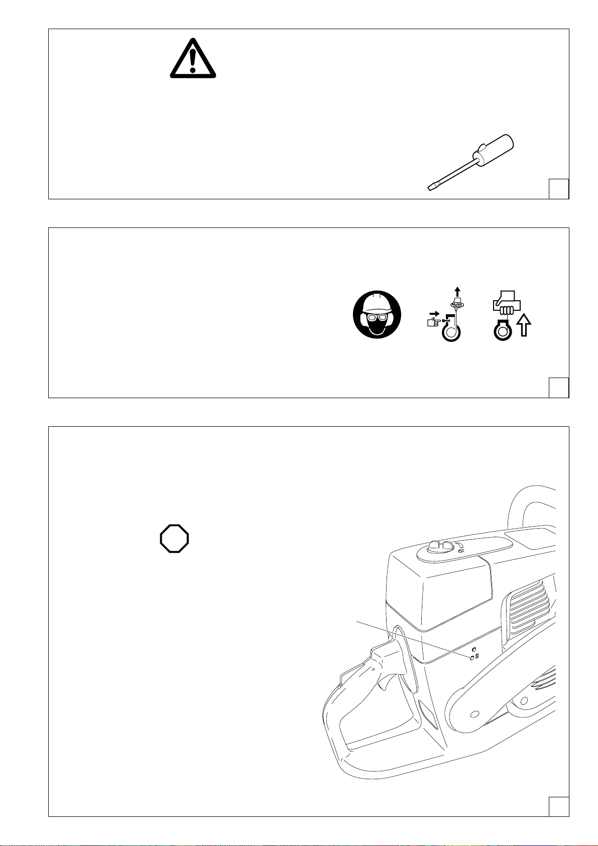
9
Adjusting
the carburetor
NOTE: The grinding parts are equipped with an electronic
ignition to limit the speed. The carburetor also has a fixed
jet which cannot be adjusted.
At the factory the idling speed has been set to approx.
2,500 1/min., but the running-in process of a new engine
may require slight readjustment of the idling speed.
For correct adjustment of the idling speed the following
steps must be carried out:
Start the engine and run it until it is warm
(about 3 - 5 minutes).
Set the idling speed with a screwdriver (width of blade: 4 mm/
0.16").
The screwdriver shown (order number 944 340 001) has a
molded-on lug to assist in adjustment.
E
2
1
F
Readjust the idling speed.
If the cut-off disc is still turning when the engine is running,
unscrew the adjusting screw of the throttle valve (9) until the
cut-off disc is no longer turning. When the engine is left
running at idling speed, loosen the screw a little.
Switch off the engine.
STOP
G
17
Page 18
A
B
STOP
SERVICE
MAINTENANCE
CAUTION:
Before doing any work on the Power Cut turn off the
engine, remove the cutting disc, pull the plug cap off the
spark plug and wear protective gloves!
CAUTION:
Start the Power Cut only after complete assembly and
inspection.
IMPORTANT:
Because many of the parts and assemblies not mentioned
in this Instruction Manual are vital to the safety of the unit,
and because all parts are subject to a certain amount of
wear and tear, it is important for your own safety that you
have the unit checked and maintained regularly by a
MAKITA service center.
IMPORTANT:
If the cutting wheel breaks during cutting, the
Power Cut must be repaired by a MAKITA service
centre before being used again!
C
7
65
8
4
3
1
2
9
10
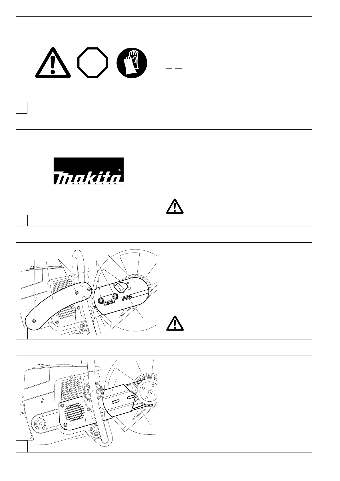
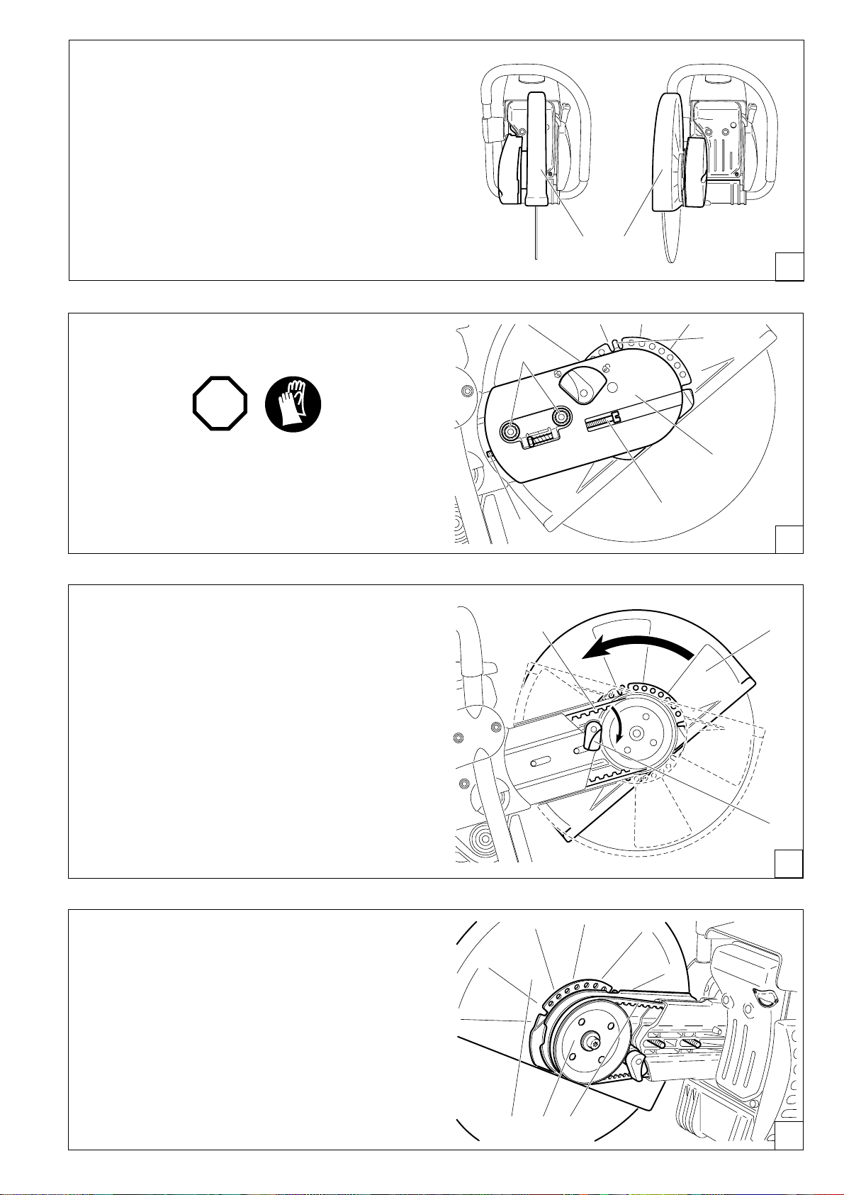
Changing the V-belt
Loosen nuts (3).
Loosen the tightening screw (1) (counter-clockwise) until the
end of the screw (2) is visible in the gap.
Unscrew the nuts (3) and remove the cover (4).
Remove the screws (5) and (7) and remove the side piece (6).
NOTE:
Screw (5) is longer than screws (7). Make sure
to put them back in the right places during
reassembly!
Unscrew screws (8) and remove the crankcase housing cover
(9).
Remove the old belt (10) or belt pieces. Clean out the inside of
the drive arm with a brush.
Put in a new V-belt.
NOTE:
Reassemble the crankcase housing cover (9), side piece (C/6)
and cover (C/4) in the reverse order.
To tighten the V-belt see ”Tightening the V-belt / Checking
V-belt tension”.
18
D
Page 19
STOP
16
17
18
Cleaning the protection hood
Over time, the inside of the protective hood can become caked
with material residue (especially from wet cutting), which if
allowed to accumulate can hinder the free rotation of the
cutting disc. For this reason the hood must be cleaned out
from time to time.
Take off the cutting wheel with spring washer and remove
the accumulated material from inside the hood with a strip of
wood or similar implement.
Clean the shaft and all disassembled parts with a cloth.
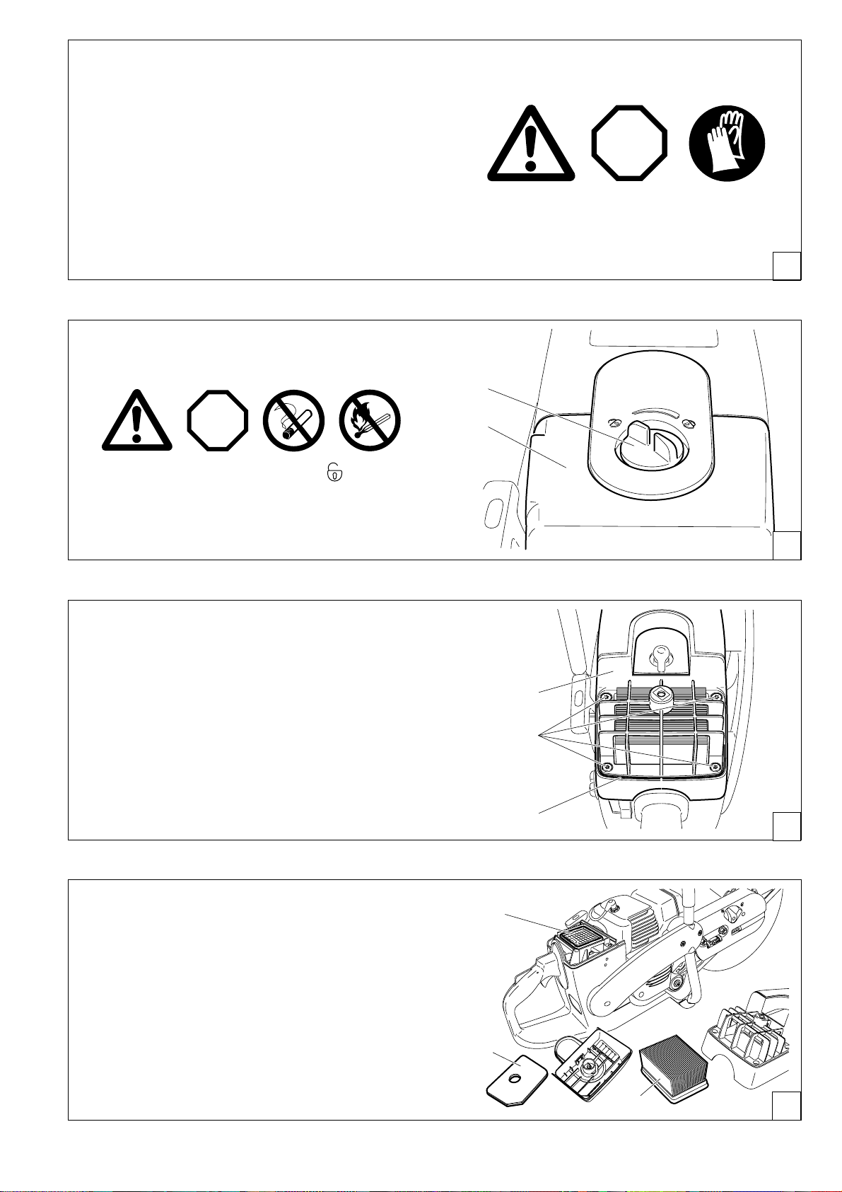
Cleaning / changing the air filter
NOTE: To install the cutting wheel see ”Mounting the cutting
wheel”.
E
11
STOP
Turn the cover lock (11) to the ”Unlocked ” position and
carefully remove the filter cover (12).
There is an O-ring (G/15) between the filter cover (12) and
the air filter hood (G/14).
Unscrew the screws (13) and remove the air filter hood (14).
Clean the O-ring (15) with a brush and inspect for damage.
12
F
14
13
15
G
Remove the foam prefilter (17) from the filter cover.
Pull the paper cartridge (18) from the hood.
Remove the inner filter (16) from the intake opening.
Note:
Do not allow dirt to get into the carburetor!
Switch the combination switch to ”Choke” or cover the
carburetor with a clean cloth.
H
19
Page 20
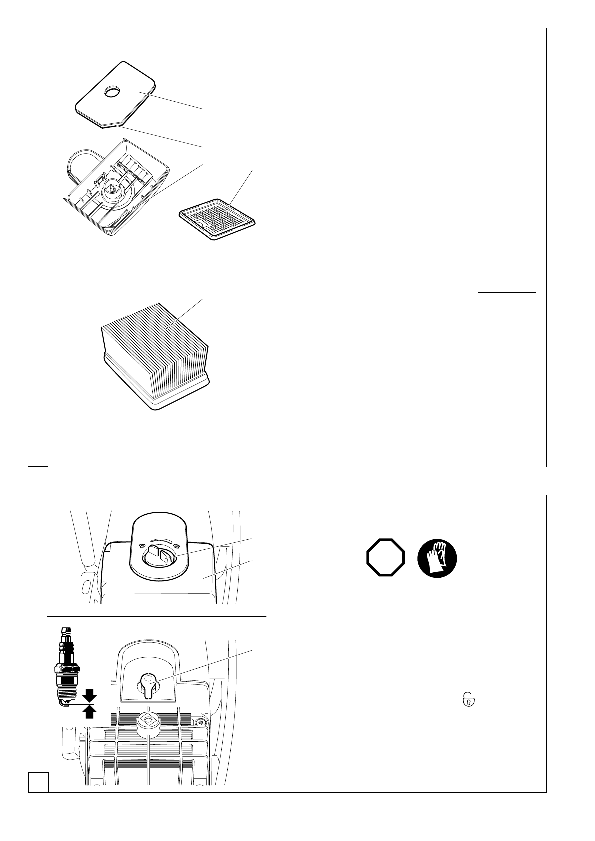
Foam prefilter and inner filter
IMPORTANT:
1
3
Do not use fuel to clean the foam prefilter and inner filter!
If the foam prefilter (1) and inner filter (2) are dirty, wash them
with dishwashing liquid in lukewarm water.
Dry thoroughly!
A
4
2
NOTE:
Under very dusty conditions it will be necessary to clean the
foam prefilter daily. If this is not possible on-site, have a
sufficient supply of reserve foam prefilters on hand.
When placing the foam prefilter in the filter cover position it with
the angled corner (3) against the angled corner in the inside of
the cover (4) and press into the filter cover.
Paper cartridge
The paper cartridge (5) filters the intake air through a very fine
paper filter laminate system. For this reason it must never be
5
washed.
Clean paper cartridge every week.
Spread the paper filter a little and tap it out on a clean surface.
Replace the cartridge periodically, and especially in case of
poor performance, reduced engine speed, or smoky exhaust.
Before reassembling the filter system, check the intake open-
ing for dirt particles, and remove any found.
CAUTION:
If the air filter becomes damaged, replace immediately!
Pieces of cloth or large dirt particles can destroy the
engine!
B
0,5 mm
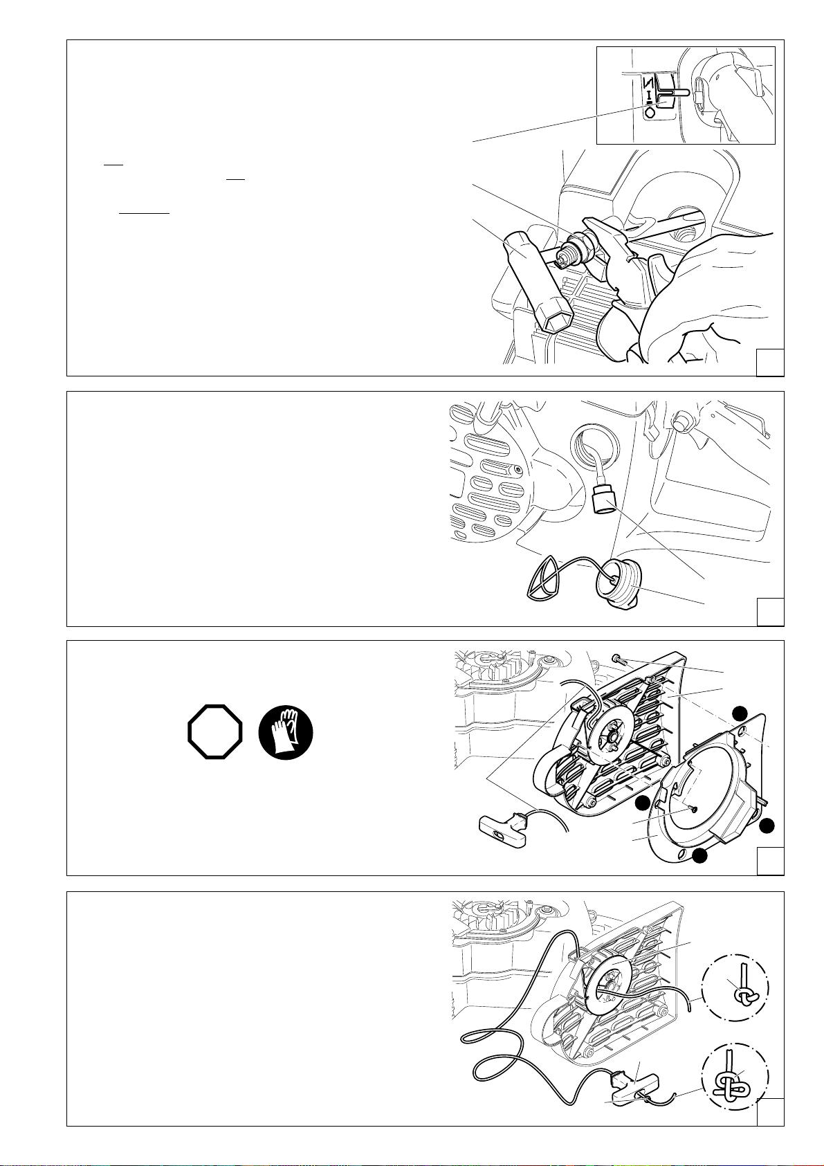
Replacing the spark plug
6
7
STOP
CAUTION:
Do not touch the spark plug or plug cap if the engine is
running (high voltage).
Switch off the engine before starting any maintenance
work.
8
A hot engine can cause burns. Wear protective gloves!
The spark plug must be replaced in case of damage to the
insulator, electrode erosion (burn) or if the electrodes are very
dirty or oily.
Turn the cover lock (6) to the ”Unlocked ” position and
carefully remove the filter cover (7).
Pull the plug cap (8) off the spark plug. Use only the combination
wrench supplied with the saw to remove the spark plug.
Electrode gap
The electrode gap must be 0.5 mm (.020").
20
Page 21
STO
P
9
10
11
Checking the ignition spark
15
18
14
17
16
A
B
C
D
22
23
19
21
20
Insert the combination wrench (9) between the hood and
cylinder only as shown.
CAUTION!
Do not insert the combination tool into the spark plug
hole, but make contact only with the cylinder (otherwise
you may damage the engine).
Using insulated pliers, hold the spark plug (10) (unscrewed
but with the plug cap on) against the combination tool (away
from the spark plug hole!).
Switch the combination switch (11) to ”I”.
Pull the starter cable hard.
If the function is correct, an ignition spark must be visible near
the electrodes.
CAUTION: Use only BOSCH WSR 6F spark plug, CHAMPION
RCJ-6Y or NGK BPMR 7A.
Replacing the suction head
The felt filter (13) of the suction head can become clogged. It is
recommended to replace the suction head once every three
months in order to ensure unimpeded fuel flow to the carburetor.
Unscrew the fuel tank cap (12) and pull the loss-prevention
stopper out.
Empty fuel tank.
To remove the suction head for replacement, pull it out through
the tank filler neck using a piece of wire bent at one end to
form a hook.
CAUTION: Do not allow fuel to come into contact with skin!
13
12
E
F
Replacing the starter cable
STOP
Unscrew four screws (14). Remove the fan housing (15).
Unscrew two screws (16) and carefully pull apart the air guide
(17) and fan housing (15). Important: Do this in the order A - B
- C - D as shown on the diagram.
Remove all pieces of cable (18).
G
Thread in a new cable (dia. 4.0 mm, length 1000 mm) as shown
in the Figure (don´t forget disc 19), and knot the ends as shown.
Pull knot (20) into the cable pulley (21).
IMPORTANT: The knot or cable end must not protrude from
the cable drum surface!
Pull knot (22) into the cable grip (23).
H
21
Page 22
A
26
24
Guide the cable into the recess (24) on the cable drum and use
the cable to turn the drum two turns in the direction shown by
the arrow.
Holding the cable drum in your left hand, straighten out the twist
in the cable with your right hand, pull the cable tight, and hold.
Release the cable drum. The drum´s spring force will now wind
the cable around the drum.
Repeat this procedure twice. The starter handle must stand out
from the fan housing.
NOTE: With the cable pulled all the way out, it must still be
possible to turn the pulley another 1/4 turn against the return
spring.
CAUTION! Injury hazard! When you pull out the starter
cable hold the starter handle firmly. It will whip back if the
cable pulley is released by accident.
Reinstall the air guide in the reverse order (fig. G on page 21).
Make sure that the guide (25) is lined up with the hole (26) in
the fan housing.
When replaceing fan housing, it may be necessary to pull the
starter cable lightly so that the cable pulley catches.
25
Replacing the return spring
Remove the fan housing (see above under “Replacing the
starter cable”).
Remove the air guide from the fan housing (see above under
“Replacing the starter cable”).
Take off circlip (1) (circlip pliers, see “Accessories”).
Remove the cable pulley (2).
5
4
3
2
1
Unscrew screw (3).
Evenly lever the return spring (4) out of the catch using a
screwdriver or similar tool. Be extremely careful - the return
spring is under tension and can pop out of its housing!
CAUTION! Injury hazard! Wear eye protection and work
gloves when performing this work!
Replacement return springs are delivered already tensioned in
the housing. CAREFUL - the spring can pop out. If it does, it
can be put back in as shown in the diagram (observe the
direction of rotation).
Grease the new return spring (4) with multi-purpose grease,
part no. 944 360 000, then insert it and tension it slightly so that
the lugs (5) click into their holes.
Screw in bolt (3) but do not tighten it hard.
Turn the cable pulley slightly when putting it back on, until you
hear it catch. Put the circlip back on.
Wind on the starter cable (see above under “Replacing the
starter cable”).
Reinstall the air guide (see Fig. A)
When replacing fan housing, it may be necessary to pull the
starter cable lightly so that the cable pulley catches.
22
B
Page 23
3
4
5
6
7
Cutting attachment in
1 2
8
9
10
1211 10
central / side position
NOTE: The Power Cut is delivered with the cutting attachment
mounted in the middle position (C). For cutting up against
obstacles, such as curbs or walls, the cutting attachment can
be mounted to one side (D). Use this position only when
actually necessary, and afterwards return the cutting attachment to the middle position. In this position the Power Cut has
better balance, is easier to guide, and is not as fatiguing for the
operator.
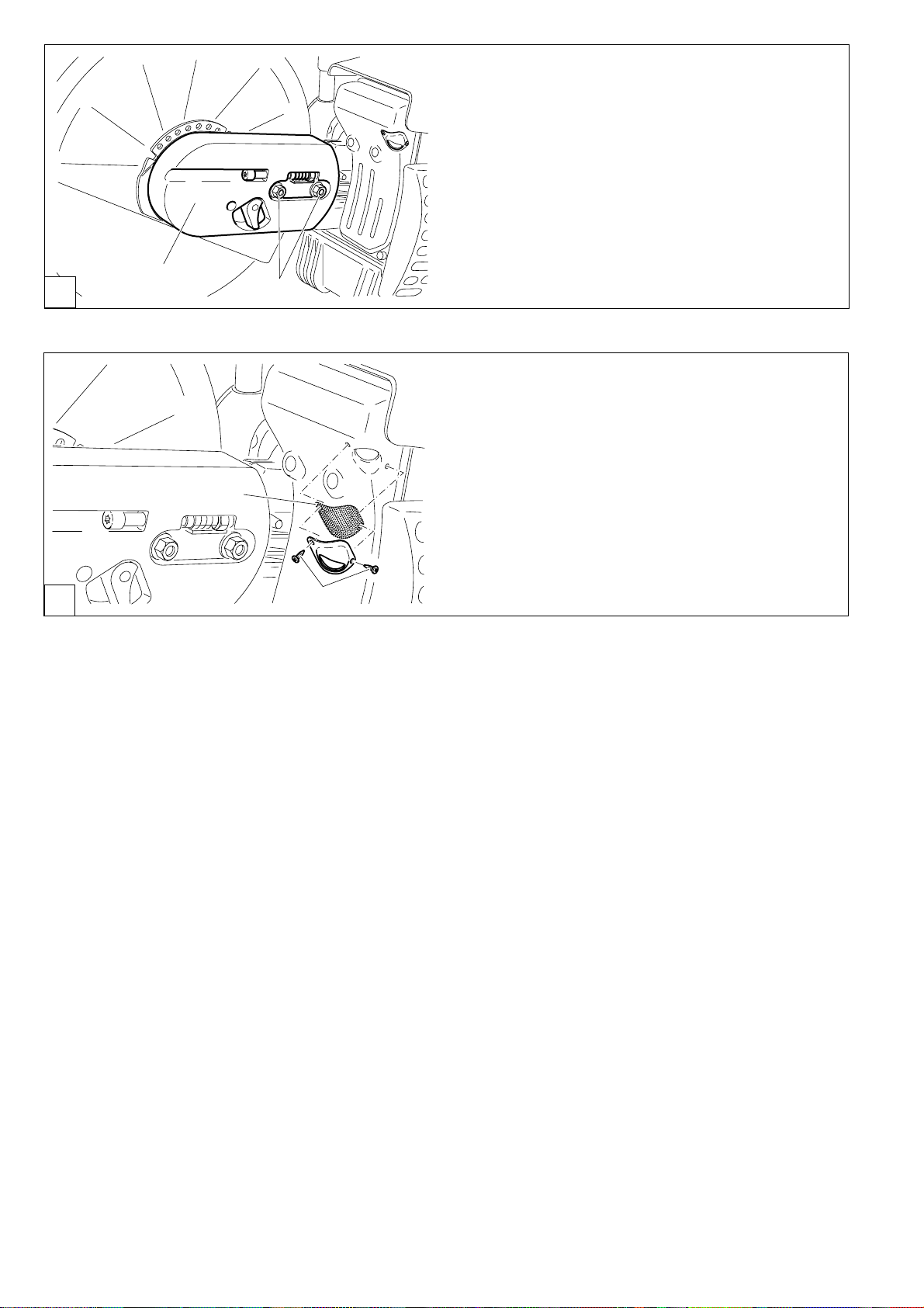
Repositioning the cutting attachment
STOP
Loosen nuts (5).
Loosen the tightening screw (3) (counter-clockwise) until the
end of the screw (4) is visible in the gap.
Unscrew the nuts (5) and remove the cover (6).
C
Turn the hood lock (8) clockwise as shown in the illustration (to
the highest point of the slanted level).
NOTE: The slip lock (Fig. D, 7) can only be overcome when the
hood lock (8) is in the position shown.
Turn the hood (9) as shown in the illustration.
Turn the hood lock (8) to the starting position and lock the hood
by turning it slightly (the hood lock will catch audibly).
Disengage the V-belt (10) and remove the cutting attachment.
Press the cutting attachment (11) in the side position onto the
drive arm attachment.
Guide the V-belt (10) over the V-belt wheel (12).
D
E
F
23
Page 24
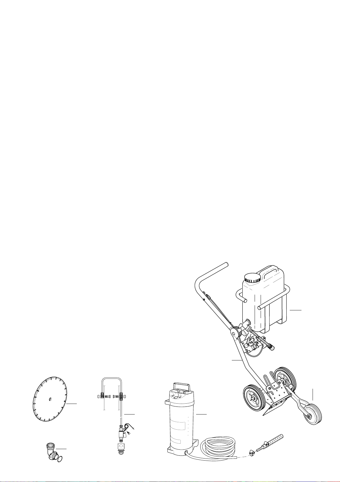
A
13
16
14
Put the guard plate (13) on.
Screw on nuts (14) and tighten by hand.
To tighten the V-belt see ”Tightening the V-belt / Checking
V-belt tension”.
Tighten the nuts (14) firmly with the combination wrench.
IMPORTANT:
When you reposition the cutting attachment, the direction
of rotation of the cutting wheel changes.
Diamond cutting wheels must be installed in the proper
direction of rotation!
Replacing/cleaning the spark arrester screen
The spark arrester screen should be checked and cleaned
regularly.
Loosen the 2 screws (15) and remove the spark arrester
screen (16).
Reassembly the spark arrester screen and tighten the screws.
B
CAUTION:
Do not use sharp or pointed objects for screen cleaning.
Damaged or misformed screen wires may result.
15
24
Page 25
SPECIAL ACCESSORIES
Diamond cutting discs (1)
MAKITA diamond cutting discs meet the highest demands in
working safety, ease of operation, and economical cutting
performance. They can be used for cutting all materials
except metal.
The high durability of the diamond grains ensures low wear and
thereby a very long service life with almost no change in disc
diameter over the lifetime of the disc. This gives consistent
cutting performance and thus high economy. The outstanding
cutting qualities of the discs make cutting easier.
The diamond discs give highly concentric running for minimal
vibration during use.
The use of diamond cutting discs reduces cutting time significantly. This in turn leads to lower operating costs (fuel consumption, wear on parts, repairs, and last but not least environmental damage).
Guide cart (2)
The MAKITA guide cart makes it much easier to do straight
cuts, while simultaneously enabling almost untiring working. It
can be adjusted for the operator´s height, and can be operated
with the cutting attachment mounted in the middle or on the
side.
For easier refuelling when using the cart, we recommend
adding an angled tank filler neck (3).
A depth limiter can be added for still easier and more accurate
cutting. It makes it possible to maintain a precise predetermined cut depth (4).
Water tank (5)
The water tank is designed to be mounted on the guide cart.
Its high capacity makes it especially suitable for situations
involving frequent site changes. For filling or for fast changing
to reserve tanks, the tank can be simply lifted off the cart.
The water tank comes with all necessary connections and
hoses. Mounting to the cart and Power Cut are very fast and
simple.
Mains/pressure water system (6)
The mains/pressure water system is designed to be mounted
on the Power Cut. It can be used with or without the cart, but
is especially suitable for applications involving hand-held,
stationary cutting. The water line has a fast-release connection, and can be fed either from a mains supply or from a
pressure tank (7).
The water system comes with all necessary connections and
lines. It can be quickly and easily mounted on the Power Cut.
See “Accessories” for order number.
To keep down dust and for better cutting-disc cooling, MAKITA
offers several options for wetting the disc during operation.
1
6
5
2
4
7
3
25
Page 26

Instructions for periodic maintenance
To ensure long life, prevent damage and ensure the full functioning of the safety features the following maintenance must be
performed regularly. Guarantee claims can be recognized only if this work is performed regularly and properly. Failure to perform
the prescribed maintenance work can lead to accidents! Users of the Power Cut must not perform any maintenance work not
described in this Instruction Manual. All such work must be carried out by a MAKITA service centre.
Page
General Entire Power Cut Clean exterior, check for damage. In case of damage,
Cutting disc Inspect regularly for damage and wear. 6
Clutch Have inspected at a service center.
Protection hood Clean 19
Before each start Cutting disc Inspect for damage and make sure the cutting wheel is 6
V-belt Check V-belt tension 13
Combination switch, Functional check
Safety locking button, Functional check
Throttle lever Functional check 15
Fuel tank cap Check for tightness
Every day Air filter Clean 19
Idle speed Check (cutting disc must not turn on idle) 17
Every week Fan housing Clean to ensure proper air cooling 11
Starter cable Check for damage 21
V-belt Check V-belt tension, inspect for damage and wear 18
Paper cartridge Clean 20
Spark plug Check and replace if necessary 20-21
Muffler Check tightness of mounting, clean spark arrester screen 11, 24
have repaired by a qualified service centre immediately
right for the job
(note: tension gauge must be purchased separately)
Every 3 months Suction head Replace 21
Fuel tank Clean
Storage Entire Power Cut Clean exterior, check for damage. In case of damage,
Cutting disc Remove and clean 12
Fuel tank Empty and clean
Carburetor Run empty
have repaired by a qualified service centre immediately
Service, spare parts and guarantee
Maintenance and repair
The maintenance and repair of modern cutoff saws and their safety-related components requires qualified technical training and a
workshop equipped with special tools and testing devices.
We therefore recommend that you consult a MAKITA service centre for all work not described in this instruction manual.
The MAKITA service centres have all the necessary equipment and skilled and experienced personnel, who can work out cost-effective
solutions and advise you in all matters.
Please contact your nearest service centre (list enclosed) or the general trading company or importer (see last page), who will gladly
provide you with the address of your nearest MAKITA service centre.
Spare parts
Reliable long-term operation, as well as the safety of your Power Cut, depend among other things on the quality of the spare parts used.
Use only original MAKITA parts, marked
Only original parts are from the same production line as the original unit and therefore ensure the highest possible quality of materials,
dimensions, functioning and safety.
Only original spare parts and accessories guarantee the highest quality in material, dimensions, functioning and safety.
Original spare parts and accessories can be obtained from your local dealer. He will also have the spare part lists to determine the
required spare part numbers, and will be constantly informed about the latest improvements and spare part innovations.
Please bear in mind that if parts other than original MAKITA spare parts are used, this will automatically invalidate the MAKITA product
guarantee.
We will furthermore not accept any liability damages arising from the use of non-MAKITA spare parts.
26
Page 27

Guarantee
MAKITA guarantees the highest quality and will therefore reimburse all costs for repair by replacement of damaged parts resulting from
material or production faults occurring within the guarantee period after purchase. Please note that in some countries particular
guarantee conditions may exist. If you have any questions, please contact your salesman, who is responsible for the guarantee of the
product.
Please note that we cannot accept any responsibility for damage caused by:
• Disregard of the instruction manual.
• Non-performance of the required maintenance and cleaning.
• Incorrect carburetor adjustment.
• Normal wear and tear.
• Obvious overloading due to permanent exceeding of the upper performance limits.
• The use of other than original MAKITA cutting discs.
• Use of force, improper use, misuse or accidents.
• Damage from overheating due to dirt on the fan housing.
• Work on the Power Cut by unskilled persons or inappropriate repairs.
• Use of unsuitable spare parts or parts which are not original MAKITA parts, insofar as they have caused the damage.
• Use of unsuitable or old oil.
• Damage related to conditions arising from lease or rent contracts.
Cleaning, servicing and adjustment work is not covered by the guarantee. All repairs covered by the guarantee must be performed by
a MAKITA service centre.
Troubleshooting
Malfunction System Observation Cause
Cutting disc does not
start turning Clutch Engine runs Damage to clutch
Engine does not start or Ignition system Ignition spark Malfunction in fuel supply system, comonly with difficulty pression system, mechanical malfunction.
No ignition spark Switch on STOP, fault or short-circuit in the
wiring, plug cap or spark plug defective.
Fuel supply Fuel tank is filled Choke in wrong position, carburetor defective,
suction head dirty, fuel line bent or interrupted.
Compression Inside Cylinder base packing ring defective, radial
system shaft packings defective, cylinder or piston rings
defective
Outside Spark plug does not seal.
Mechanical Starter does not engage Spring in starter broken, broken parts
malfunction inside the engine.
Warm start difficulties Carburetor Fuel tank is filled Wrong carburetor adjustment.
Ignition spark
Engine starts, but Fuel supply Fuel tank is filled Wrong idling adjustment, suction head or
dies immediately carburetor dirty.
Tank venting defective, fuel line interrupted,
cable defective, STOP switch defective. Starting
valve dirty.
Insufficient power Several systems Engine is idling Air filter dirty, wrong carburetor adjustment,
may be involved muffler clogged, exhaust channel in cylinder
simultaneously clogged, spark arrester screen clogged.
27
Page 28

Extract from the spare parts list
Use only original MAKITA parts. For repairs and
replacement of other parts, see your MAKITA service centre.
DPC 6400, 6401
DPC 7300, 7301
14
6
Pos. MAKITA-No. Qty. Denomination
Synthetic resin cutting disc
1 966 121 150 1 Cutting disc for steel,
1 966 121 120 1 Cutting disc for masonry,
1 966 144 150 1 Cutting disc for steel,
1 966 144 120 1 Cutting disc for masonry,
3 994 280 250 1 Hex screw M8x25
4 965 300 470 1 V-belt
5 963 601 130 1 Suction head
6 010 114 091 1 Fuel tank cap, cpl.
8 394 173 020 1 Inner filter
9 394 173 010 1 Paper cartridge
10 394 173 030 1 Foam prefilter
11 965 603 021 1 Spark plug
12 122 164 010 1 Starter cable ø 4,0x1000 mm
13 001 161 010 1 Starter grip
14 394 163 020 1 Return spring
15 923 208 004 2 Hexagonal nut M8
16 394 174 140 1 Spark arrester screen cpl.
19 941 719 140 1 Universal wrench SW 13/19
20 940 827 000 1 Offset screwdriver T27
21 944 340 001 1 Carburetor adjustment screwdriver
dia. 300 mm /12"
dia. 300 mm / 12"
dia. 350 mm /14"
dia. 350 mm / 14"
10
9
8
12
13
3 1
16
11
5
27
26
25
24
20 2119415
Accessories (not delivered with the Power Cut)
22 966 221 020 1 Concrete Standard, dia. 300 mm / 12"
22 966 321 020 1 Concrete DiaDuran, dia. 300 mm / 12"
22 966 221 010 1 Asphalt Standard, dia. 300 mm / 12"
22 966 321 010 1 Asphalt DiaDuran, dia. 300 mm / 12"
22 966 241 020 1 Concrete Standard, dia. 350 mm / 14"
22 966 341 020 1 Concrete DiaDuran, dia. 350 mm / 14"
22 966 241 010 1 Asphalt Standard, dia. 350 mm / 14"
22 966 341 010 1 Asphalt DiaDuran, dia. 350 mm / 14"
23 950 233 210 1 Tachometer
24 010 114 081 1 Angle fuel-tank filler neck, cpl.
25 700 394 353 1 Guide cart DT 2000 cpl.
26 957 802 600 1 Pressure water tank, cpl.
27 394 365 600 1 Mains water connection, cpl.
- 949 000 031 1 Combined can (for 5l fuel, 2.5l oil)
-
394 228 120 1 Adapter 20/25,4 mm
Diamond cutting disc
28
22
23
Page 29

Notes
29
Page 30

Nous vous remercions de votre confiance!
La découpeuse moderne de MAKITA vous a convaincu à
l’achat. Comme des tronçonneuses MAKITA, les découpeuses
MAKITA sont équipées de moteurs haute puissance
spécialement construits à cet effet présentant un rapport
puissance / poids excellent, donc une puissance moteur élevée
pour un poids faible. Autres avantages des découpeuses
MAKITA:
• construction robuste et haute fiabilité.
• allumage électronique nécessitant aucun entretien, protégé
hermétiquement contre la poussière et l’humidité.
• amortissement des vibrations selon le système 2 masses
MAKITA (D2M) garantissant un travail sans fatigue même
pour un appareil portatif.
• Système de filtre à air à cinq niveaux pour un fonctionnement
fiable même en cas d’important dégagement de poussières.
• deux possibilités de montage du disque à découper: en
position moyenne pour le balancement optimal de l’appareil
portatif ou en position latérale pour des coupes effectuées
près de murs ou en bordures de routes ou horizontal
directement au-dessus du sol.
• divers accessoires de disques à découper à la résine ou au
diamant ainsi que chariot de guidage avec amortissement
contre les vibrations, collecteur de poussière et différents
système d’amenée d’eau vers le disque à découper.
Dans l’appareil ont été observés les droits de protection
suivants: US 08510690, SE 95027298, SE 95027306, IT
95000653, IT 95000654, GBM 9412558, GBM 9412559.
Notre plus grande attente est que vous soyez un client
MAKITA satisfait.
Afin de garantir en permanence un fonctionnement optimal de
votre découpeuse MAKITA et d’assurer votre sécurité
personnelle, nous vous demandons de:
Lire attentivement ce manuel d’instructions et de sécurité
avant la première mise en route et veuillez observer avant
tout les prescriptions de sécurité! La non-observation de
ces instructions risque d’entraîner des blessures
mortelles!
ATTENTION!
Certaines poussières produites pendant le décapage au
sable, le sciage, l’affûtage, le perçage et pendant d’autres
travaux de coupe de matériaux, contiennent des substances
chimiques qui peuvent causer le cancer, des difformités de
naissance ou d’autres conséquences ultérieures dues à la
concentration dans le corps (Californie, Etats-Unis).
Quelques exemples de ces substances chimiques:
• plomb provenant de peintures à base de plomb
• silicate cristallisé venant de briques, du ciment
et d’autres produits de maçonnerie
• arsenic et chrome provenant de bois traité
chimiquement
Le risque dépend de la fréquence des travaux indiqués avec
ces substances chimiques. Pour réduire votre exposition
à ces substances chimiques: Ne travailler uniquement
que qu’à des endroits bien aérés, et avec l’équipement de
protection approuvé tel que le masque anti-poussières
conçu pour filtrer les micro-particules.
Sommaire Page
Emballage..........................................................................30
Etendue de la fourniture ..................................................31
Symboles ...........................................................................31
INSTRUCTIONS DE SÉCURITÉ
Instructions générales...................................................32
Equipement de protection personnel...................... 32-33
Produits de fonctionnement /Remplissage des
réservoirs ......................................................................33
Mise en route ................................................................33
Disques à découper ......................................................34
Rebond (klickback) et freinage .....................................35
Comportement et technique de travail .........................35
Découper les métaux ....................................................36
Découper pierre, béton, amiante ou asphalte ........ 36-37
Transport et stockage ...................................................37
Maintenance..................................................................38
Premier secours............................................................38
Caractéristiques techniques ...........................................39
Désignation des pièces....................................................39
MISE EN ROUTE
Montage du disque à découper ....................................40
Tendre la courroie / Contrôler la tension ......................41
Carburants / ravitaillement...................................... 41-42
Démarrer le moteur................................................. 42-43
Démarrage à froid .........................................................43
Démarrage à chaud ......................................................43
Comportement à suivre en cas de pannes...................44
Arrêter le moteur ...........................................................44
Marche hivernale ..........................................................44
Réglage du carburateur ...................................................45
TRAVAUX DE MAINTENANCE
Remplacer la courroie...................................................46
Nettoyer le capot de protection.....................................47
Nettoyer / remplacer le filtre à air ........................... 47-48
Remplacement de bougie.............................................48
Remplacement de la crépine d’aspiration ....................49
Remplacement du cordon de lancement................ 49-50
Remplacement du ressort de rappel ............................50
Indications de maintenance et d’entretien périodiques 54
Dispositif de coupe en positon médiane /
position extérieure ..................................................... 51-52
Démonter le dispositif de coupe ............................. 51-52
ACCESSOIRES SPECIAUX
Disques à découper au diamant, chariot de guidage,
réservoir à eau et conduite d’eau sous pression..........53
Service d’atelier, pièces de rechange et garantie... 54-55
Recherche de pannes ......................................................55
Extrait de la liste des pièces de rechange.....................56
Accessoires...................................................................56
Liste d'ateliers spécialisé ................................................86
Emballage
Votre découpeuse MAKITA est emballée dans un carton pour
éviter tout dommage durant le transport.
Les cartons sont des matières premières recyclables, ils peuvent
donc être remis dans le cycle de la matière première (réutilisation
des vieux papiers).
RE Y
30
Page 31

Etendue de la fourniture
STOP
34521
1. Découpeuse
2. Disque à découper
3. Outillage de montage 13/19
4. Tournevis coudé
5. Tournevis pour carburateur
6. Manuel d’instructions et de sécurité (sans illustration)
Si un des composants indiqués ici ne devait pas être dans la
fourniture, veuillez vous adresser à votre vendeur!
Symboles
Vous rencontrerez les symboles suivants sur l’appareil et dans le manuel d’instructions et de sécurité:
Lire manuel d’instrutions et
suivre les consignes de sécurité
et d’avertissement!
Danger et attention particuliers!
Interdit!
Porter le casque, les lunettes et
acoustiques de protection!
Porter des gants de protection!
Porter l’appareil de respiration!
Interdiction de fumer!
2
1
STOP
Commutateur combiné
Marche/Arrêt (E/S), starter
Verrouillé / Déverrouillé
Appuyer sur la soupape de mise
en marche
Démarrer le moteur
Marche hivernale
Arrêter le moteur!
Attention,
Rebond (kickback)!
Pas de feu ouvert!
Sens de rotation du
disque à découper
Attention: vitesse périphérique max.
de la disque à découper 80 m/s!
Dimensions du disque à découper
Mélange carburant
Premier secours
Recyclage
RE Y
31
Page 32

FE
A
B
C
D
INSTRUCTIONS DE SÉCURITÉ
Instructions générales
- Pour pouvoir manipuler l’appareil en toute sécurité,
l’utilisateur devra lire impérativement les présentes
instructions d’emploi (même si celui-ci a déjà travaillé
avec une découpeuse) de manière à se familiariser avec le
maniement de cette découpeuse. Par une utilisation inadéquate,
des serveurs insuffisamment informés et formés présentent
un danger pour eux-mêmes et pour d’autres personnes.
- Ne prêter uniquement la découpeuse qu’à des utilisateurs
ayant déjà manipulé une découpeuse. Les instructions d’emploi
doivent être transmises à cette fin.
- Nous conseillons aux utilisateurs novices de consulter un
spécialiste de manière à se familiariser avec les caractéristiques
de la découpe assurée par moteur.
- Les enfants et adolescents âgés de moins de 18 ans ne sont
pas autorisés à se servir de la découpeuse. Les adolescents
au-dessus de 16 ans sont exempte de cette interdiction que, si
pour des besoins de formation, ils sont sous la direction d’un
professionnel.
- Le travail avec la découpeuse exige une grande attention.
- Ne travailler qu’en bonne condition physique. Une fatigue, par
exemple, peut conduire à un inattention. Il faut particulièrement
faire attention à la fatigue de la fin de journée de travail.
Exécuter tous les travaux tranquillement et avec prudence. Le
serveur est d’autre part responsable par rapport à des tiers.
- Ne jamais travailler sous l’effet de l’alcool, de drogues, de
médicaments ou d’autres substances risquant d’affecter la
vue, l’aptitude ou les réflexes.
- Avoir un extincteur sous la main en cas de travaux dans un
végétation facilement inflammable ou par temps de sécheresse
(Danger d’incendie).
- Le découpage de l’amiante ou de substances susceptibles de
dégager des gaz toxiques ne doit être effectué qu’après en
avoir fait la demande et sous la surveillance des autorités
compétentes en la matière ou de la personne chargée de ce
travail tout en recourant aux mesures de sécurité
indispensables.
1
2
Equipement de protection personnel
- Pour éviter lors du découpage des blessures à la tête, aux
yeux, aux mains, aux pieds, ainsi qu’une baisse de
l’audition, il faut porter les équipements et moyens de
protection corporels suivants.
- Les vêtements doivent s’appliquer judicieusement au corps
sans toutefois présenter une gène. Les vêtements dans lesquels
des grains de matériau peuvent pénétrer (par exemple pantalon
à ourlet, vestes ou pantalons dont les poches sont ouvertes
etc.) ne peuvent être portés notamment lors du découpage de
métal.
- Ne pas porter de bijoux ou de vêtements pouvant se coincer ou
gêner l’utilisateur pendant le découpage.
- Porter pour l’ensemble des travaux un casque de protection
(A). Le casque de protection doit régulièrement être vérifié s’il
n’est pas endommagé et il doit être échangé au plus tard après
5 ans. N’utiliser que des casques agrées.
- Le masque (B) du casque stoppe la poussière d’abrasion et
les grains de matériau. Pour éviter toute blessures des yeux et
du visage, un masque ou des lunettes de protection (C) ou
doivent être portées pendant l’utilisation de la découpeuse.
- Pour éviter des dommages auditifs, il faut porter des moyens
de protection acoustiques personnels appropriés (casque
protège-oreilles (D), capsules, ouate à la cire, etc.). Analyse
par bandes d’octaves sur demande.
- Le découpage à sec de matériau pierreux produisant de la fine
poussière (pierre, béton etc.) exige impérativement le port d’un
appareil respiratoire (E) conforme aux prescriptions.
- Des gants de travail (F) en cuir résistant font partie de
l’équipement réglementaire et doivent être portés en
p
32
ermanence lors de l’utilisation de la découpeuse.
3
4
Page 33

H
G
- Des gants ou des bottes de sécurité (G) à semelle crantée,
une casquette en acier et un protège-jambe doivent être portés
pendant l’utilisation de la découpeuse. Les chaussures de
sécurité avec des recouvrements anti-coupure offre une
protection contre des blessures par coupure et assurent une
assise sure.
- Porter en permanence une combinaison de travail (H) en
matière résistante pour tout type de travaux.
Produits de fonctionnement / Remplissage des réservoirs
- Avant de remplir le réservoir d’essence, chercher un endroit sûr
et plat. Remplir le réservoir sur un échafaudage ou une pile
de matériaux ou objet similaire est interdit!
- Avant de remplir le réservoir d’essence de la découpeuse,
arrêter le moteur.
- Interdiction de fumer, et éviter tout feu ouvert à proximité (6).
- Avant de remplir le réservoir, laisser refroidir l’appareil.
- Les carburants peuvent contenir des substances assimilables
à des dissolvants. Eviter de rentrer en contact avec la peau et
avec les yeux avec les produits pétroliers. Lors du remplissage,
porter des gants (non pas les gants de travail). Changer
souvent de vêtements de protection et les nettoyez. Ne pas
respirer des vapeurs de carburants. La respiration de vapeurs
de carburant peut entraîner des dommages corporels.
- Ne jamais répandre du carburant. Si du carburant a été versé à
côté, nettoyer immédiatement la découpeuse. Ne pas mettre le
carburant en contact avec les vêtements. Si du carburant est
déversé sur les vêtements, changer immédiatement de vêtement.
- Veillez à ce que du carburant ne pénètre dans le sol (protection
de l’environnement). Utiliser des substrats adéquats.
- Ne pas faire le plein dans un local fermé, les vapeurs des
carburants s’amassent au sol (danger d’explosion).
- Bien fermer les capuchons vissés de réservoir à essence.
- Pour démarrer la découpeuse, changer d’emplacement (au
moins 3 mètres (10 pieds) de l’endroit où le remplissage a été
effectué) (7), non pas dans la prolongation de la zone de
pivotement (sens de projection des étincelles) du disque à
découper.
- Les carburants ne peuvent pas être stockés infiniment. N’acheter
que la quantité nécessaire couvrant un temps de marche
prévisible.
- Lorsque vous effectuez le mélange essence-huile, remplir
d’abord l’huile et ensuite l’essence dans le bac de mélange.
- Ne transporter et ne stocker le carburant que dans des nourrices
agrées et portant les indications nécessaires.
- Ne jamais laisser le carburant à la portée des enfants.
Mise en route
- Ne jamais travailler tout seul, en cas d’urgence quelqu’un
doit être à proximité (portée de la voix).
- Respecter les règlements en matière de protection contre les
bruits lors de l’utilisation de la découpeuse dans des zones
d’habitation.
- La découpeuse ne doit pas être utilisée à proximité de
matières combustibles ou de gaz explosifs. Il y a risque de
formation d’étincelles.
-S’assurer que les personnes se trouvant à moins de 30 m (100
pieds) de l’emplacement de travail (par ex. aides) portent un
équipement de protection (voir „Equipement de protection
personnel“) (8). Les enfants ou autres personnes doivent respecter
une distance minimale de 30 m (100 pieds) de la zone de travail
de la découpeuse. Attention également aux animaux (9).
- Avant le début du travail, contrôler le fonctionnement
parfait et l’état réglementaire de fonctionnement des
sécurités de la découpeuse.
Vérifier notamment l’état du disque à découper (remplacer
immédiatement les disques fissurés, endommagés ou
déformés), contrôlez si le disque à découper est bien monté, le
capot de protection enclenché, la protection de courroie bien
fixée, la courroie tendue correctement. Vérifiez également si le
levier de gaz, le verrouillage de levier de gaz et le commutateur
combiné fonctionnement correctement et si les poignées sont
propres et sèches.
- Ne mettre la découpeuse qu’en service après l’avoir
complètement assemblée et vérifiée. En principe, la découpeuse
ne doit être utilisée qu’à l’état complètement monté.
5
6
7
30 m (100 pieds)
8
9
3 mètres
(10 pieds)
= porter l’équipement de protection
33
Page 34

Disques à découper
- Le capot de protection doit toujours être monté. Ne remplacer
le disque à découper que lorsque le moteur est éteint!
- Il y a deux types de disques à découper:
- pour le métal (coupe à chaud)
- pour le béton (coupe à froid)
REMARQUE: Lorsque vous utilisez des disques à découper au
diamant, respecter impérativement la marque du sens de rotation
indiquée. Les disques à découper au diamant ne conviennent pas
pour le traitement du métal.
- Les disques à découper ne sont conçus qu’en vue d’un effort
radial pour la coupe. Ne jamais utiliser les faces latérales du
disque à découper pour poncer. Risque de rupture, donc
interdit! (10)
Attention! Il est interdit de changer de sens (rayons inférieurs
à 5 m -16 pieds-), d’appuyer latéralement sur la découpeuse ou
de la basculer pendant le découpage (11)!
- Les disques à découper ne doivent être utilisés que pour
tronçonner les matériaux prédéfinis. Le type de disque
correspondant doit être sélectionné en fonction du matériau
(métal ou béton).
- Le trou de forage intérieur du disque à découper doit s’adapter
exactement à l’arbre. Un trou de forage intérieur plus grand doit
être compensé par un anneau intermédiaire.
Le disque à découper doit être homologué par le DSA (organisme
-
allemand pour le contrôle des disques) pour une découpe à
main levée et présenter les caractéristiques suivantes: un
diamètre de 14”/350 mm jusqu’à 4370 t/min. ou 80 m/s ou bien
un diamètre de 300 mm jusqu’à 5100 t/min. ou 80 m/s.
- Le disque à découper doit être en parfait état (12).
Serrer toujours la vis de fixation du disque à découper à 30 Nm
sinon risque de torsion du disque.
- Avant de démarrer, le guide de la découpeuse doit prendre une
position stable.
-Ne démarrer la découpeuse que selon les instructions indiquées
dans la notice d’emploi (13).
la poignée et entourer la poignée avec le pouce.
techniques de lancement ne sont pas autorisées.
- Lors de la mise en route, la machine doit être solidement
maintenue et supportée. Pour cela, le disque à découper doit
être libre.
- Si le disque à découper est neuf, il doit être testé avant le premier
découpage au moins pendant 60 secondes à la vitesse maximale
indiquée. Pour cela, aucune partie du corps ou personne doit se
trouver dans la prolongation de la zone de pivotement du disque
à découper.
- Lors du travail, la découpeuse est à maintenir avec les deux
mains. La main droite maintient la poignée arrière, la main
gauche la poignée en forme d’étrier. Bien saisir les poignée avec
les pouces.
- ATTENTION: Dès que l’accélérateur est relâché, le disque à
découper tourne à vide pendant une courte durée (effet de
marche à vide).
- Il faut veiller constamment à avoir une bonne assise sure.
- La découpeuse est à manipuler pour que les gaz d’évacuation
ne peuvent pas être inspirés. Ne pas travailler dans des pièces
closes ou dans des fossés profonds (risque d’intoxication).
- Arrêter immédiatement la découpeuse lorsqu’on sent des
modifications dans son comportement.
Avant de vérifier la tension de la courroie, pour la retendre,
-
remplacer le disque à découper, ou changer le montage du
dispositif de découpe (position extérieure ou médiane) et
pour recourir à toute panne, il est impératif de mettre le
moteur hors service (14).
- En cas de changement audible ou sensible dans le découpage,
arrêter immédiatement le moteur) et vérifier le disque à découper.
- La découpeuse doit être arrêtée pendant les pauses et à la fin
du travail (14), elle doit être mise à l’arrêt de façon à ce que le
disque soit libre et que personne ne soit en danger.
- Ne pas poser la découpeuse chaude dans de l’herbe sèche ou
sur des objets inflammables. Le pot d’échappement rayonne
énormément de chaleur (danger d’incendie).
- ATTENTION: A l’issue du découpage sous arrosage, arrêter
d’abord l’arrosage et ensuite laisser tourner le disque à découper
pendant au moins 30 secondes de manière à faire évacuer l’eau
et empêcher la corrosion.
Poser toujours le peid droit gauche
D’autres
13
14
10
11
12
min. 5 m
(16 pieds)
P
O
T
S
● Maintenance
● Ravitaillement
● Remplacer le disque
à découper
● Démonter le dispositif
de découpage
● Pause de travail
● Transport
● Mise hors service
34
Page 35

Rebond (kickback) et freinage
- Un rebond ou freinage dangereux peut se produire en travaillant
avec la découpeuse.
- Le rebond se produit lorsque la partie supérieure du disque est
utilisé pour découper (15).
- La découpeuse est incontrôlée, accélérée et lancée en avant
avec une grande énergie en direction du guide-découpeuse
(risque de blessure!).
Pour éviter tout rebond, respecter les consignes suivantes:
- Ne jamais tronçonner avec le segment montré sur la figure 15!
Faites très attention lorsque vous découpez dans des
entailles!
- Le freinage se produit quand l’entaille est comprimée (fissure
ou pièce sous tension).
- La découpeuse est incontrôlée, accelérée et landée en avant
avec une grande énergie (risque de blessure!).
Pour éviter tout rebond, respecter les consignes suivantes:
- Toujours découper et réintroduire la lame dans des entailles à
plein régime.
- Toujours caler la pièce de manière à ce que l’entaille soit sous
tension de traction (16) pour ne pas que le disque à découpe
ne coince.
- Au début du découpage, toujours approcher le disque à
découper avec précaution, sans à-coups.
- Ne jamais tronçonner plusieurs pièces à la fois! Veiller à ce
qu’aucune autre pièce ne soit touchée lors du découpage.
15
Comportement et technique de travail
- Avant de commencer à travailler, vérifier si la zone de travail
ne présente aucun risque (câbles électriques, substances
inflammables). Délimiter la zone de travail bien distinctement
(en utilisant par exemple des panneaux d’avertissement ou
des barrages quelconques).
- Utilisez la découpeuse en la tenant correctement par la poignée
avant et arrière. Ne jamais laisser la découpeuse sans aucune
surveillance!
- Utiliser si possible la découpeuse au régime nominal de
broche (voir page «Caractéristiques techniques»).
- Ne travailler que sous de bonnes conditions de visibilité et
d’éclairage. Faire particulièrement attention en présence de
sol glissant, d’humidité, de glace et de neige (danger de
glissade).
- Ne jamais travailler sur un fondement instable. Faire attention
aux obstacles dans la zone de travail (risque de trébucher).
Continuellement veiller à avoir une assise solide et sure.
- Ne jamais découper au-dessus de la hauteur d’épaule (17).
- Ne jamais découper debout sur une échelle (17).
- Ne jamais travailler avec la découpeuse sur un échafaudage.
- Ne jamais travailler trop penché en avant. Toujours fléchir les
genoux en posant ou en prenant la découpeuse. Ne pas se
courber.
- Conduire la découpeuse de manière à ce qu’aucune partie du
corps ne se trouve dans la prolongation de la zone de pivotement
du disque à découper (18).
- Les disques à découper ne doivent être utilisés que pour
découper les matières prévues.
- Ne pas utiliser la découpeuse pour enlever et balayer les
restes de pièces et autres objets.
Attention risque de blessure! Nettoyer la zone de coupe
avant le découpage de corps étrangers tels que pierre, clous
etc. Ceux-ci peuvent être projetés lors de la coupe et provoquer
des blessures.
- Lors du tronçonnement de pièces, utiliser un support stable et
le fixer si nécessaire pour ne pas qu’il ne glisse. La pièce ne
doit pas être bloquée avec le pied ou par une autre personne.
- Les pièces rondes doivent être impérativement fixées pour ne
pas qu’elles se tordent dans la coupe.
-N’utiliser qu’en cas de besoin la découpeuse portative avec
dispositif de découpage en position extérieure. La découpeuse
avec dispositif de découpage en position médiane a un meilleur
équilibre évitant ainsi une fatigue prématurée.
16
17
18
35
Page 36

Découper les métaux
ATTENTION!
Porter l’appareil respiratoire réglementaire!
Le découpage de matières pouvant dégager des gaz toxiques
ne peut être effectué qu’après en avoir fait la demande et sous
la surveillance des autorités compétentes ou de la personne
en étant chargée.
ATTENTION!
Les métaux chauffent et fondent par la rotation rapide du
disque à découper au point de contact. Basculer le capot de
protection vers le bas le plus loin possible derrière la coupe
(19) pour diriger la protection d’étincelles si possible vers
l’avant, dans le sens opposé de l’opérateur (risque d’incendie
important).
-Déterminer et marquer le sens de découpage et approcher le
disque vers le matériau à une vitesse moyenne et dès qu’une
rainure de guidage est entaillée, continuer de couper à plein
régime en appuyant fortement.
- Couper uniquement droit et verticalement, ne pas tenir de
travers, sinon le disque risque de se rompre.
- On obtient une coupe optimale et égale en tirant et en faisant
aller et venir la découpeuse. Ne pas „pousser“ le disque à
découper dans la matière.
- Tronçonner les barres rondes massives de préférence par
étapes (20).
- Les tubes minces peuvent être simplement découpés en
coupant verticalement.
- Manipuler les tubes de grand diamètre comme les barres
massives. Pour éviter de tenir de travers et pour un meilleur
contrôle du découpage, ne pas laisser le disque trop pénétrer
dans le matériau. Toujours tronçonner à plat tout autour.
- Les disques à découper usées de faible diamètre ont au même
régime moins de vitesse périphérique et coupent par
conséquent moins bien.
- Tronçonner les supports en double T ou cornières par étapes,
voir figure 21.
- On découpe les fers feuillards ou plaques en fer comme les
tubes; tirer à plat, avec longue surface de coupe .
- Toujours entailler d’abord le matériau se trouvant sous tension
(matériau buté ou emmuré) légèrement sur le côté de poussée
et ensuite tronçonner depuis le côté de traction pour ne pas
que le disque ne se coince. Bloquer la pièce à découper de
manière à ce qu’elle ne puisse pas tomber!
ATTENTION:
En cas de crainte de prétension, s’attendre au rebond du
matériau et assurer au préalable une possibilité de recul.
Une attention particulière est requise dans les parcs à
ferrailles, sur les lieux d’accident ou en cas de piles de
matériaux en désordre. Il est difficile de prévoir les réactions
d’un matériau se trouvant sous tension, en train de glisser ou
de voler en éclats. Bloquer la pièce à découper de manière à
ce qu’elle ne puisse pas tomber! Travailler avec la plus
grande attention et avec un appareil impeccable.
Respecter les prescriptions en matière d’accidents du travail
de la caisse d’assurance mutuelle compétente et de
l’assurance.
19
20
21
Découper la pierre, le béton, l’amiante ou l’asphalte
ATTENTION!
Porter l’appareil respiratoire réglementaire!
Le découpage de l’amiante ou de matières pouvant dégager
des gaz toxiques ne peut être effectué qu’après en avoir fait
la demande et sous la surveillance des autorités compétentes
ou de la personne en étant chargée. Pour la coupe de poteaux
en béton armés et précontraints, il faut se reporter aux
consignes et aux normes fournies par les autorités
compétentes ou par le fabriquant. Le découpage de barres
d’armature doit être exécuté dans l’ordre réglementaire et en
respectant les consignes de sécurité correspondantes.
REMARQUE:
L’enduit à mortier, la pierre ou le béton entraînent une très fine
poussière lors du découpage. Pour prolonger la durée de vie du
36
Page 37

disque à découper (refroidissement), pour un meilleur contrôle
visuel et pour éviter un dégagement de poussière excessif, il est
préférable de découper au mouillé plutôt qu’à sec. Pour cela, le
disque à découper doit être arrosé d’eau de manière égale des
deux côtés. Dans la gamme MAKITA, vous trouverez à toute fin
d’utilisation le bon équipement pour le découpage au mouillé (voir
également „ACCESSOIRES SPECIAUX“.
- Nettoyer l’endroit de la coupe en éliminant les corps étrangers
tels que sable, pierres, clous etc.. Attention: Faites attention
aux câbles électriques!
Par la rotation rapide du disque à découper, le matériau est
arraché au point de contact et projeté en-dehors de la rainure
de coupe. Basculer vers le bas le capot de protection aussi
loin que possible derrière la coupe (23) pour diriger les
particules de matière découpées si possible vers l’avant,
dans le sens contraire de l’utilisateur.
- Marquer le tracé de coupe et tailler sur toute la longueur une
rainure d’env. 5 mm (1/5") de profondeur à demi-gaz que la
découpeuse finira exactement.
REMARQUE:
Pour les longues coupes droites, il est recommandé d’utiliser le
chariot de guidage (24, voir également „ACCESSOIRES
SPECIAUX“). Celui-ci permet de conduire facilement la
découpeuse en ligne droite en déployant peu de force.
- Le découpage est exécuté par des mouvements de va-etvient égaux.
- Lors de la pose de plaques de pierre, il suffit de tailler une
rainure plate (pour éviter le dégagement de poussière inutile)
afin d’enlever proprement le morceau saillant sur un support
plat (25).
ATTENTION!
Fixer impérativement le sens de coupe et l’ordre des coupes à
effectuer pour des coupes de mise à longueur, ruptures,
évidements etc. pour éviter que le morceau découpé ne coince le
disque à découper et pour éviter toute blessure par les morceaux
qui tombent.
23
24
Transport et stockage
- La découpeuse doit être à l’arrêt lors du transport et lors
d’un changement de lieu pendant le travail (26).
- Ne jamais porter et transporter la découpeuse pendant
que le moteur ou le disque est en marche.
- Ne porter la découpeuse que par la poignée-étrier. Le disque
à découper est orienté vers l’arrière (26). Ne jamais entrer en
contact avec le pot d’échappement (risque de brûlure).
- Utiliser une brouette ou un chariot pour le transport sur une
distance assez longue.
- Si la découpeuse est transportée par un véhicule automobile,
s’assurer que celle-ci soit dans une position sûre pour éviter
l’écoulement du carburant. Toujours démonter la découpeuse
pour le transport en véhicule automobile.
- Entreposer la découpeuse de manière sûre dans un local sec.
Elle ne doit pas être stockée en plein air. Toujours démonter
la découpeuse. Ne jamais laisser la découpeuse à la portée
des enfants.
- Avant un entreposage prolongé et avant l’expédition de
la découpeuse, suivre impérativement les consignes
indiquées dans le chapitre „Consignes de maintenance
et d’entretien périodiques“. Vider à chaque fois le
carburant et faire tourner le carburateur à vide.
- Pour l’entreposage des disques à découper, procéder
attentivement de manière suivante:
- nettoyer et bien sécher.
- toujours stocker à plat.
- Il est impératif d’éviter l’humidité, le gel, les rayons directs du
soleil, les températures élevées ou les variations de
température, sinon risque de rupture et d’éclat éventuel!
- Vérifier avant l’utilisation si les disques à découper neufs
ou stockés sont endommagés.
25
STOP
26
37
Page 38

Maintenance
STOP
- Pour tous les travaux de maintenance, arrêter la
découpeuse (27) et retirer la fiche de la bougie!
-Vérifier avant de commencer à travailler si l’état de la
découpeuse est fiable. S’assurer que le disque à découper
est monté en fonction des prescriptions. S’assurer que le
disque à découper n’est pas endommagé et convient
exactement pour l’utilisation prévue.
- La machine doit fonctionner avec le moins de bruit et de gaz
d’échappement possibles. Ceci suppose un bon réglage du
carburateur.
- Nettoyer régulièrement la découpeuse.
-Vérifier régulièrement si le bouchon du réservoir est étanche.
Respecter les prescriptions de prévoyance contre les
accidents de la corporation professionnelle
correspondante et de l’assurance. N’effectuer aucune
modifications de construction de la découpeuse. Vous
risquez votre sécurité.
Les travaux de maintenance et de réparations à exécuter sont
limités à ceux précisés dans la notice d’emploi. Tous les
autres travaux doivent être effectués par le Service Après
Vente de MAKITA.
N’utiliser que les pièces détachées et accessoires MAKITA
d’origine.
En cas d’utilisation de pièces détachées, accessoires n’étant
pas d’origine MAKITA, il faut s’attendre à un risque d’accident
important. MAKITA ne pourra être tenu responsable en cas
d’accidents ou de dommages avec des disques à découper
ou accessoires n’étant pas d’origine.
27
SERVICE
28
Premier secours
On devra toujours disposer sur le lieu de travail d’une boîte de
secours pour le cas d’un éventuel accident. Les produits
prélevés doivent immédiatement être remplacés.
Si vous appelez du secours, veuillez indiquer:
- le lieu de l’accident
- ce qui s’est passé
- le nombre de blessés
- le type de blessures
- le nom du demandeur
REMARQUE
Des dériorations au niveau des vaisseaux sanguins ou du systè-
me nerveux peuvent se produire chez des personnes souffrant
de troubles circulatoires et trop souvent soumises à des vibrations.
Les symptomes pouvant apparaitre à la suite de vibrations au
niveau des doigts, mains ou articulations sont les suivants:
engourdissement de membres corporels, chatouillement, douleurs, points, changement du teint ou de la peau.
Si ce genre de symptomes apparaissent, consultez un médecin.
29
38
Page 39

Caractéristiques techniques
DPC 6400 DPC 6401 DPC 7300 DPC 7301
Cylindrée cu in (cm3) 3,9 (64) 4,5 (73)
Alésage in (mm) 1,85 (47) 1,97 (50)
Course in (mm) 1,46 (37) 1,46 (37)
Puissance max. hp (kW) 4,3 (3,2) 5,6 (4,2)
Couple max. Nm 4,0 5,0
Vitesse de rotation à vide rpm 2.500 2.500
Vitesse de rotation d’embrayage rpm 3.800 3.800
Régime d’étranglement rpm 9.350 9.350
Régime nominal de broche rpm 4.300 4.300
Niveau sonore à l’oreille de l’opérateur
1)
Niveau sonore à la position de l’assistant (50 pieds)
Accélération d’oscillation a
selon EN 1454
h,w
- poignée-étrier (Ralenti / régime nominal de broche) m/s
- poignée (Ralenti / régime nominal de broche) m/s
dB (A) 97 104
1)
dB (A) 84 86
2
2
6 / 5 7 / 6
8 / 6 8 / 7
Carburateur (à membrane) Type TILLOTSON HS-273 A
Dispositif d’allumage (avec limiteur de vitesse de rotation) Type électronique
Bougie d’allumage Type
NGK BPMR 7A / BOSCH WSR 6F / CHAMPION RCJ 6Y
Ecartement électrodes in (mm) .020 (0,5) .020 (0,5)
Consommation carburant/puissance max. selon ISO 8893 kg/h 1,65 2,1
Consommation spéc./puissance max. selon ISO 8893 g/kWh 500 500
Capacité réservoir carburant fl oz (l) 37 (1,1) 37 (1,1)
Dosage mélange (carburant/huile 2 temps)
- avec utilisation huile MAKITA HP 100 100:1 100:1
- avec utilisation huile MAKITA 50:1 50:1
Disque à découper pour 80 m/s
Diamètre de broche in (mm) 20 mm 20 mm 20 mm 20 mm
Courroie n
Poids de la découpeuse
2) 3)
(homologué DSA)
(réservoirs vides, sans disque) lb 21.38 21.82 21.60 22.04
dimensions: in (mm)
o
12” / 20mm / 0,2”
14” / 20 mm / 0,2” 12” / 20mm / 0,2”
965 300 470 965 300 470
14” / 20 mm / 0,2”
1)
Selon les exigences d’essai UL en pleine charge (coupe concrète).
2)
Vitesse périphérique pour régime max.
3)
diamètre extérieur / trou de réception / épaisseur
Désignation des pièces
DPC 7301
0201 123456
EMI OFB
973108
22045 Hamburg, Germany
394.100.661 Typ 394
1 Poignée
2 Couvercle de filtre pour filtre à air
et fiche de bougie
3 Pièce de verrouillage du couvercle
4 Poignée-étrier
5 Silencieux avec pare-étincelles
6 Capot de protection
7 Pièce de verrouillage du capot de protection
8 Vis de réglage pour la tension de courroie
9 Ecrous de fixation
10 Béquille
11 Orifices pour le réglage du carburateur
12 Plaque signalétique
13 Réservoir avec protége-main
14 Soupape de mise en marche
15 Poingnée de lancement
16 Orifice d’aspiration d’air
17 Commutateur combiné
«Marche/Arrêt» (E/S), starter
18 Arretier-Knopf für Halbgas
19 Bouton de blocage pour mi-gaz
20 Levier de gaz
21 Bouchon de fermeture du réservoir carburant
22 Carter ventilateur avec dispositif de lancement
23 Disque à découper
24 Vis de fixation du disque à découper
25 Disque de contrainte
Plaque signatique (12)
à indiquer lors de commande de pièces de rechange!
Numéro de série
Année de construction
25
24
23
3 4 5 6
2
1
7
8
9
12 1113
10
14 15 16
17
18
19
20
2122
39
Page 40

A
STOP
MISE EN ROUTE
ATTENTION:
Pour tout travail effectué sur la découpeuse, il est impératif
de mettre le moteur hors tension, de retirer la fiche de la
bougie et de porter des gants de protection!
ATTENTION:
La découpeuse ne peut être mise en marche qu’après le
montage complet!
Pour les travaux suivants, utilisez l’outillage compris dans la
fourniture:
1. Clé combinée SW 13/19
2. Tournevis coudé
3. Tournevis pour le réglage du carburateur
B
C
Poser la découpeuse sur un support stable et effectuer les
1
2
3
Schématique
7
5
5
7
98
opérations suivantes pour le montage du disque à découper:
Monter le disque à découper
Vérifier si le disque à découper est en bon
état, voir CONSIGNES DE SECURITE page 32.
Dévisser la vis (9) et retirer le disque de contrainte (8).
Avant le montage, veiller à ce que le porte-outil et les moyeux
sont absolument propres.
Poser le disque à découper (5) sur l’arbre (7).
En cas d'utilisation de meules avec 1" comme diamètre
intérieur, poser la bague d'adaptation (*) disponible en option,
no. de pièce 394 228 120.
ATTENTION: Respecter impérativement le sens de rotation
en cas d’utilisation de disques à découper en diamant.
40
D
10
Poser le disque de contrainte (8) sur l’arbre, visser la vis (C/9)
8
2
1
à l’intérieur et la serrer à la main.
Tourner lentement le disque à découper jusqu’à ce que l’on
puisse voir le trou d’arrêt du disque de la courroie dans le trou
de forage du bras de transmission (10).
Enfoncer entièrement le tournevis coudé (2). L’arbre est
maintenant bloqué.
Bien serrer la vis au moyen de la clé combinée (1).
NOTE: Bien serrer la vis (30 ± 2 Nm). Le disque à découper
risque sinon de se tordre.
Page 41

Tendre la courroie /
Contrôler la tension
ATTENTION:
Il est indispensable de tendre correctement la courroie de
manière à atteindre le rendement de coupe désirée et à
garantir une consommation de carburant optimale. Une
tension incorrecte de la courroie provoque l’usure
prématurée de celle-ci et des disques de courroie ou
détériore le logement d’embrayage.
NOTE: Pour tendre la courroie et pour vérifier la tension, il faut
dévisser les écrous de fixation (11).
Pour augmenter la tension, tourner la vis de tension (12) vers
la droite (dans le sens des aiguilles) au moyen de la clé
combinée comprise dans la fourniture.
La courroie est correctement réglée si l’écrou (13) se trouve au
milieu du repère (14).
STOP
E
13
ATTENTION: Après avoir tendu la tension et
contrôlé la tension, il est impératif de bien serrer les
écrous de fixation (11) (30 ± 2 Nm).
Carburants
ATTENTION:
L’appareil est utilisé avec des produits d’huiles minérales
(essence et huile)!
Votre attention est requise lorsque vous manipulez
l’essence.
Il est interdit de fumer et tout feu immédiat n’est pas
autorisé (risque d’explosion).
Mélange carburant
Le moteur de la découpeuse est un moteur à deux temps de
haute capacité. Ce moteur est alimenté par un mélange de
carburant et d’huile moteur deux temps.
La conception du moteur a été réalisé pour fonctionner à
l’essence normal sans plomb avec un degré d’octane minimum
de 91 ROZ. Si un tel type de carburant n’était pas disponible,
on peut aussi utiliser un carburant d’un degré d’octane plus
élevé. Le moteur n’en subit aucun dommage.
Pour un fonctionnement optimal, ainsi que pour la protection de la santé et de l’environnement, utilisez toujours
un carburant sans plomb. Il ne faut pas utiliser d’essence
contenant de l’alcool avec les produits MAKITA.
Le graissage du moteur est réalisé par une huile moteur à deux
temps (échelle de qualité TC-3) qui est additionnée au carburant.
En usine le moteur a été réglé pour l’huile moteur deux temps
très performante de MAKITA HP 100 avec un rapport de
mélange de 100:1. Ceci garantit une longue durée de vie et un
fonctionnement fiable avec un très faible dégagement de fumées
du moteur.
11 12
14
Carburant
+
1.0 Us-gal. (3.7 litres) 1.25 floz. (37 cm3) 2.6 floz. (75 cm3)
2.5 Us-gal. (9.4 litres) 3.2 floz. (94 cm3) 6.4 floz. (189 cm3)
5.0 Us-gal. (18.9 litres) 6.4 floz. (189 cm3) 12.8 floz. (378 cm3)
Réalisation du rapport correct du mélange:
100:1 En utilisant l’huile deux temps de haute perfor-
mance MAKITA HP 100, ceci signifie mélanger
100 parties d’essence avec une partie d’huile.
50:1 En utilisant l’huile deux temps de haute perfor-
mance MAKITA, ceci signifie mélanger 50 parties d’essence avec une partie d’huile.
100:1
HP 100
F
50:1
OIL
50:1
G
41
Page 42

L’huile deux temps de haute performance MAKITA HP 100
peut être livrée selon les besoins dans des bidons aux
contenances suivantes:
0,5 l N° de commande 980 008 609
L’huile deux temps de haute performance MAKITA (50:1)
peut être livrée selon les besoins dans des bidons aux
contenances suivantes:
1 l N° de commande 980 008 607
100 ml N° de commande 980 008 606
REMARQUE: Pour fabriquer le mélange essence-huile, il
faut toujours mélanger préalablement le volume d’huile
prévu dans la moitié du volume d’essence, puis y ajouter le
volume d’essence restant. Avant de verser le mélange dans
l’appareil, bien le mélanger au préalable.
Attention: Ouvrir le bouchon du réservoir d’essence avec
précaution. Risque de montée de pression.
Il n’est pas raisonnable que par excès de conscience de
sécurité d’augmenter la part d’huile au delà du rapport
indiqué du mélange, le résultat serait plus de résidus de
combustion ce qui polluerait l’environnement et
A
boucherait la sortie d’échappement dans le cylindre,
ainsi que le silencieux. En outre, la consommation de
carburant augmenterait et la puissance diminuerait.
Stockage du carburant
Les carburants ne sont stockables que jusqu’à un certain
point. N’acheter le carburant que pour 4 semains d’utilisation.
Ne stocker le carburant que dans des fûts autorisés et
signalisés en conséquence.
EVITEZ LE CONTACT AVEC LA PEAU ET LES YEUX
Les produits pétroliers, ainsi que les huiles, dégraissent la
peau. Lors d’un contact répété et prolongé la peau se
dessèche. Les suites peuvent être différentes maladies de
peau. D’autre part, on connait les réactions allergiques.
Le contact avec les yeux de l’huile conduit à des irritations.
en cas de contact, rincer immédiatement l’oeil avec de l’eau
claire.
Si l’irritation continue, consulter immédiatement un médecin.
B
STOP
Mélange carburant
1
Remplissage des réservoirs
ATTENTION: RESPECTER IMPERATIVEMENT LES
REGLES DE SECURITE!
La manipulation de carburants exige une manipulation
avec précaution et prudence.
Opération à effectuer uniquement lorsque le moteur est
arrêté et refroidi!
Bien nettoyer autour de la zone de remplissage pour éviter
qu’aucune saleté n’entre dans le réservoir.
Poser la machine de coté sur un support plat.
Dévisser le bouchon du réservoir et verser le mélange de
carburant. Verser avec précaution pour ne pas renverser le
mélange.
Revisser fermement le capuchon du réservoir.
Nettoyer le capuchon et le pourtour après remplissage! Ne
jamais démarrer ou utiliser l’appareil là où l’essence y a
été versée.
Démarrer le moteur
si
42
nécessaire
Le modèle est équipé d’une soupape de mise en marche semiautomatique (1) (HappyStart) qui facilite le démarrage. Le fait
d’enfoncer la soupape de mise en marche réduit le travail de
compression et le moteur peut alors être accéléré à une vitesse
de démarrage avec un minimum de force utilisée au niveau du
cordon de lancement.
Etant donné que la pression s’élève sensiblement dans la
chambre d’explosion à la suite des premiers allumages, la
soupape de mise en marche se ferme automatiquement (le
bouton ressort).
C
Page 43

ATTENTION:
5
4
6
7
8
Respecter impérativement les INSTRUCTIONS DE SÉCURITÉ de la page 33.
La découpeuse ne peut être mise en marche qu’après le
montage complet!
Démarrer le moteur au moins 3 m (10 pieds) de l’endroit du
réservoir.
Prendre une position sure et poser la découpeuse de
manière à ce que le dispositif de découpage ne soit tourné
dans votre direction.
2
1
3 mètres
(10 pieds)
D
Tourner la pièce de verrouillage du capot de protection (2) en
position et la maintenir.
Basculer le capot de protection (3) vers l’arrière jusqu’à la
butée.
Relâcher la pièce de verrouillage du capot de protection, faire
aller et venir le capot de protection de façon à ce que la pièce
de verrouillage s’enclenche.
Démarrage à froid
Pousser le commutateur combiné (5) vers le haut (position
starter).
Saisir la poignée (la paume de la main appuie sur le bouton
d’arrêt de sécurité (7)).
Enfoncer le levier de gaz (8) et le maintenir.
Pousser la tête d’enclenchement (6) et relâcher le levier de gaz
(8) (le levier de gaz est bloqué par la tête d’enclenchement en
position demi-gaz).
IMPORTANT: Si la découpeuse est montée sur le chariot de
guidage, le levier de réglage doit être mis au deuxième cran.
Enfoncer la soupape de mise en marche (4).
3
2
E
F
Tenir la poignée-étrier à pleine main et appuyer la découpeuse
contre le sol.
Poser la pointe du pied gauche dans le pare-main.
Tirer vite et fort sur le cordon de lancement, jusqu’au déclenchement du premier allumage
Attention: Ne pas retirer le cordon de lancement de plus de
50 cm (20") et le ramener lentement à la main.
Enfoncer à nouveau la soupape de mise en marche (F/4).
Pousser le commutateur combiné (F/5) en position «I».
Tirer à nouveau le cordon de lancement jusq’à ce que le moteur
tourne.
Dès que le moteur tourne, actionner le levier de gaz (F/8) pour
que le bouton de blocage (F/6) ressorte et pour que le moteur
tourne au ralenti.
audible.
Démarrage à chaud
Comme décrit dans le paragraphe concernant le démarrage à
froid, toutefois sans utiliser le commutateur combiné (F/5) en
position starter.
G
43
Page 44

A
P
O
ST
1
STOP
Arrêter le moteur
Pousser le commutateur combiné (1) vers le bas en position .
STOP
Marche hivernale
Pour éviter le givrage du carburateur, se produisant en cas de
basses températures et de forte humidité de l’air, il est possible
d’aspirer de l’air chaud de la cavité du cylindre en cas de
températures inférieures à 0° C. La température de service est
alors plus vite atteinte.
Pour des températures supérieures à 0° C, de l’air froid
doit être impérativement aspiré.
En ne respectant pas cette consigne, le cylindre et le
piston peuvent être endommagés!
B
C
Tourner la pièce de verrouillage du couvercle (2) en position
«déverrouillé » et enlever le couvercle du filtre (3) avec
2
précaution.
3
Enlever l’élément de filtrage (4) du couvercle du filtre.
4
Enlever la cartouche Eté-Hiver de la position Eté (7) et l’enfoncer
comme montré sur la figure dans la position Hiver (8).
44
D
NOTE: En cas de températures supérieures à 0° C, il est
impératif de mettre la cartouche Eté-Hiver en position Eté (7)!
NOTE: En l’insérant dans le couvercle du filtre, aligner l’élément
de filtrage (4) avec le côté chanfreiné (5) vers la réception du
6
5
87
couvercle (6) et l’enfoncer dans le couvercle du filtre.
Page 45

Réglage du carburateur
9
REMARQUE: Les découpeuses sont équipées d’un allumage électronique à limitation de vitesse de rotation. Le
carburateur est en outre muni d’une buse fixe non réglable faisant office de gicleur principal.
Le régime de ralenti est préréglé en usine sur env. 2.500
1/min; il se peut néanmoins que la procédure de rodage
d’une nouvelle machine exige une léger rajustage du
régime de ralenti.
Les opérations suivantes sont nécessaires pour un réglage correct du régime de ralenti:
Démarrez le moteur et laissez-le tourner jusqu’à ce qu’il
soit chaud (env. 3 à 5 min.).
Réglage du régime de ralenti avec un tournevis (lame de 4 mm/
0.16"). Le tournevis de la photo (N° de commande 944 340
001) dispose d’un nez coulé servant au réglage.
E
2
1
Corrigez le réglage du régime de ralenti
Si le disque à découper tourne avec le moteur, dévissez la vis
de butée (9) du papillon du carburateur jusqu’à ce que le
disque ne tourne plus. Si le moteur s’arrête lorsqu’il tourne à
vide, revissez à nouveau légèrement la vis de butée.
Arrêtez le moteur
STOP
F
G
45
Page 46

TRAVAUX DE MAINTENANCE
ATTENTION:
A
B
STOP
SERVICE
Pour tout travail sur la d´copeuse, il est impératif d’arrêter
le moteur, de retirer le disque `découper, de tirer la cosse
de bougie et de porter les gants de protection!
ATTENTION:
La découpeuse ne peut être mise en marche qu’après le
montage complet!
IMPORTANT:
Etant donné que nombreuses pièces non abordées dans
ce manuel d’utilisation sont en partie des dispositifs de
sécurité importants et comme toute pièce est également
soumise à une certaine usure, une vérification et
maintenance régulière doit être effectuée par un atelier
spécialisé MAKITA pour garantir votre sécurité.
ATTENTION:
Si le disque à découper se fracture pendant la
découpe, l’appareil doit être révisé par un atelier
agréé MAKITA avant toute remise en marche!
C
7
65
8
4
3
1
2
9
10
Remplacer la courroie
Desserrer les écrous (3).
Desserrer la vis de tension (1) (dans le sens inverse des
aiguilles) jusqu’à ce que l’extrémité de la vis (2) soit visible
dans la fente.
Dévisser les écrous (3) et enlever le couvercle (4).
Dévisser les vis (5) et (7) et retirer l’entretoise latérale (6).
NOTE:
La vis (5) est plus longue que la vis (7).
Observer la position de montage.
Desserrer les vis (8) et retirer le couvercle du carter-moteur (9).
Enlever l’ancienne courroie (10) ou les restes de courroie.
Nettoyer l’intérieur du bras de transmission au moyen d’un
pinceau.
Mettre en place une nouvelle courroie.
NOTE:
Montage du couvercle du carter-moteur (9), de l’entretoise
latérale (C/6) et du couvercle (C/4) dans l’ordre inverse.
Tendre la courroie comme décrit au chapitre «Tendre la
courroie / Contrôler la tension».
46
D
Page 47

11
12
16
17
18
Nettoyer le capot de protection
A l’intérieur de la tôle de protection se constituent des dépôts
de matière (notamment lors du découpage au mouillé)
susceptibles d’empêcher la rotation du disque à découper.
Démonter le disque à découper et le disque de pression.
Enlever les dépôts de découpe à l’intérieur du capot de
protection au moyen d’un bâton en bois ou d’un objet similaire.
Nettoyer l’arbre et toutes les pièces démontées avec un
chiffon.
Nettoyer / remplacer le filtre à air
STOP
Tourner la pièce de verrouillage du couvercle (11) en position
«déverrouillé » et enlever le couvercle du filtre (12) avec
précaution.
Une bague d’étanchéité (G/15) se trouve entre le couvercle du
filtre (12) et le capot (G/14).
STOP
NOTE: Montage du disque à découper voir chapitre «Montage
du disque à découper».
E
F
Dévisser les vis (13) et retirer le capot (14).
Nettoyer la bague d’étanchéité (15) au moyen d’un pinceau et
vérifier si elle est endommagée.
Enlever le préfiltre en mousse (17) du couvercle du filtre.
Tirer la cartouche de papier (18) hors du capot.
Enlever le filtre intérieur (16) de la crépine d’aspiration.
Note:
Protéger le carburateur de manière à ce qu’aucune
poussière n’y pénètre.
Mettre le commutateur combiné en position «starter» ou
couvrir le carburateur d’un chiffon propre.
14
13
15
G
H
47
Page 48

Préfiltre en mousse et filtre intérieur
ATTENTION:
Ne pas nettoyer le préfiltre en mousse et le filtre intérieur
avec de l’essence.
1
3
4
2
Laver le préfiltre en mousse encrassé (1) et le filtre intérieur (2)
dans une eau de savon tiède avec un produit à laver la Bien
sécher le préfiltre en mousse et le filtre intérieur.
IMPORTANT:
Il est conseillé de nettoyer une fois par jour le préfiltre en
mousse en cas de fort dégagement de poussière. Avoir toujours
un préfiltre de réserve au cas où il n’est pas possible de le
nettoyer sur place.
Poser le préfiltre en mousse avec le côté chanfreiné (3) vers la
réception du couvercle (4) en l’insérant dans le couvercle du
filtre et l’enfoncer dans le couvercle du filtre.
Cartouche de papier
La cartouche de papier (5) filtre l’air aspiré au moyen d’un
système très fin de lamelles de filtrage en papier. C’est pourquoi
la cartouche
5
Nettoyer la cartouche de papier une fois par semaine.
Répartir légèrement les cases de la cartouche de papier et la
frapper avec précaution contre un support propre.
Remplacer la cartouche de papier régulièrement. Au plus tard
après une perte de puissance, chute de régime ou fumée dans
les gaz d’échappement.
Avant le montage du système de filtrage, contrôler l’orifice
d’aspiration si il n’y a pas de particule de saleté. Les enlever le
cas échéant.
ne doit être en aucun cas lavée.
ATTENTION:
Remplacer aussitôt le filtre à air endommagé!
Des morceaux de tissu déchirés et des particules de
salissure grossières peuvent détériorer le moteur.
A
B
0,5 mm
Remplacement de bougie
6
7
STOP
ATTENTION:
Les bougies d’allumage ou la fiche de la bougie ne doivent
pas être touchés le moteur en marche (haute tension).
N’effectuer des travaux de maintenance que si le moteur
est arrêté.
Risque de brûlure lorsque le moteur est chaud: porter
8
absolument vos gants de protection!
En cas de détérioration du corps isolant, d’usure importante
des électrodes resp. d’électrodes très encrassées ou pleines
d’huile, il faut procéder à un remplacement de la bougie.
Tourner la pièce de verrouillage du couvercle (6) en position
«déverrouillé » et retirer le couvercle du filtre (7) avec
précaution.
Retirer la fiche de la bougie (8) de la bougie. Démonter la
bougie uniquement avec la clé combinée comprise dans la
fourniture.
Ecartement des électrodes
L’écartement des électrodes doit être de 0,5 mm (.020").
48
Page 49

STOP
9
10
11
Vérification de l’étincelle d’allumage
15
18
14
17
16
A
B
C
D
22
23
19
21
20
N’introduire la clé combinée (9) entre le capot et le cylindre que
comme montré sur la figure.
ATTENTION!
Ne pas introduire la clé dans le trou de bougie, établir
seulement un contact avec le cylindre (sinon risque de
détérioration du moteur).
Presser contre la clé la bougie (10) dévissée avec la cosse bien
posée au moyen d’une clé
de bougie!)
Pousser le commutateur combiné (11) en position «l».
Tirer fortement sur le cordon de lancement.
En fonctionnement correct, l’étincelle doit être visible sur les
électrodes.
ATTENTION: N’utilisez comme rechange que les bougie
BOSCH WSR 6F, CHAMPION RCJ-6Y oder NGK BPMR 7A.
isolée (dans le sens inverse du trou
Remplacement de la crépine d’aspiration
Le filtre feutre (13) de la crépine d’aspiration peut se boucher
pendant l’utilisation. Pour assurer une alimentation sans
problème du carburant vers le carburateur, la crépine
d’aspiration devra être remplacée environ tous les 3 mois.
Dévisser le bouchon d’essence (12). Enlever l’anti-perte de
l’orifice du réservoir.
Nettoyer le réservoir carburant.
Retirer la crépine d’aspiration avec un crochet en fil de fer à
travers l’orifice de fermeture du réservoir.
Attention: Eviter de rentrer en contact avec la peau et avec les
yeux avec les produits pétroliers.
13
12
E
F
Remplacement du cordon de lancement
STOP
Retirer les quatre vis (14). Enlever le carter du ventilateur (15).
Dévisser les deux vis (16) et enlever avec précaution le
déflecteur de ventilateur (17) du carter du ventilateur (15).
Respecter l’ordre (A – B – C – D).
Enlever les anciens restes de cordon (18).
G
Enfiler le nouveau cordon (ø 4,0 mm, 1000 mm de long)
comme indiqué sur la figure (ne pas oublier le disque (19)) et
nouer les deux extrémités.
Insérer le noeud (20) dans le tambour d’enroulement (21).
ATTENTION : Le nœud ou l’extrémité du cordon ne doit en
aucun cas déborder de la surface du tambour.
Insérer le noeud (22) dans la poignée de lancement (23).
H
49
Page 50

A
26
24
25
Introduire le cordon dans l’évidement (24) sur le tambour
d’enroulement et tourner deux fois le tambour d’enroulement
avec le cordon dans le sens de la flèche.
Tenir le tambour d’enroulement de la main gauche, démêler le
cordon de la main droite, tendre et tenir le cordon.
Lâcher le tambour. Par l’effet de ressort, le cordon s’enroule
sur le tambour.
Répéter deux fois l’opération. La poignée de lancement doit
être droite sur le carter du ventilateur.
INDICATION: Si la corde de lancement est tirée fortement, le
tambour d’enroulement doit pouvoir faire un moins un 1/4 de
tour contre l’effort de ressort.
ATTENTION:
Risque de blessure! Bien tenir la poignée de lancement qui
a été tirée vers l’extérieur. Elle peut rebondir en arrière si
vous relâchez par inadvertance le tambour d’enroulement.
Monter le déflecteur de ventilateur (voir Fig. G, page 21) dans
l’ordre inverse. Veiller à ce que la pièce de guidage (25) soit
bien dans le logement (26) sur le carter du ventilateur.
Lors de la pose du carter de ventilateur, tirer légèrement si
nécessaire la poignée de lancement jusqu’à ce que le dispositif
de lancement s’enclenche.
B
Remplacement du
ressort de rappel
Enlever le carter du ventilateur (voir chapitre „Remplacement
de la corde de lancement“).
Retirer le déflecteur de ventilateur du carter de ventilateur (voir
chapitre „Remplacement de la corde de lancement“).
Enlever le circlip (1) (pince pour les circlips extérieurs, voir
accessoires).
5
4
3
2
1
Retirer le tambour d’enroulement (2).
Dévisser les vis (3).
Soulever le ressort de rappel (4) de son ancrage au moyen d’un
tournevis ou d’un outil similaire en un mouvement régulier en
recourant à une attention extrême. Le ressort de rappel est
prétendu et peut sauter de la cassette !
ATTENTION ! : Risque de blessure ! Porter impérativement
des lunettes de protection et des gants de protection en
effectuant ce travail !
Les ressorts de rappel de remplacement sont fournis tendus
dans le carter. ATTENTION, le ressort de rappel peut sauter.
Une fois enlevé, le ressort de rappel peut être réinséré comme
suit (respecter le sens de rotation !).
Avant le montage, graisser légèrement le nouveau ressort de
rappel (4) dans le carter du ventilateur avec de la graisse
universelle, n° de commande 944 360 000, ensuite insérer le
ressort de rappel (4) et le presser légèrement de façon à ce que
les attaches (5) viennent s’enclencher dans les logements.
Introduire la vis (3) et ne la serrer que légèrement.
Tourner légèrement le tambour d’enroulement en le posant
jusqu’à ce qu’il s’enclenche correctement. Monter le circlip
Enrouler le cordon de lancement (voir chapitre „Remplace-
ment de la corde de lancement“).
Monter le déflecteur de ventilateur (voir Fig. A).
Lors de la pose du carter de ventilateur, tirer légèrement si
nécessaire la poignée de lancement jusqu’à ce que le dispositif
de lancement s’enclenche.
50
Page 51

3
4
5
6
7
Dispositif de coupe en positon médiane /
1 2
8
9
10
1211 10
position extérieure
ATTENTION: Le dispositif de découpage a été monté par
l’usine pour le montage en position médiane (1). En cas
d’obstacles se trouvant à toute proximité du tracé du découpage
(par exemple bordure ou murs), le dispositif de découpage peut
être monté en position extérieure (2). N’utilisez la position
extérieure de la découpeuse que pour le travail à effectuer.
Remontez-la ensuite en position médiane. Quand le dispositif
de découpage est en position médiane, la découpeuse a un
meilleur centre de gravité empêchant ainsi une fatigue
prématurée.
Démonter le dispositif de coupe
STOP
Desserrer les écrous (3).
Desserrer la vis de tension (3) (dans le sens inverse des
aiguilles) jusqu’à ce que l’extrémité de la vis (4) soit visible
dans la fente.
Dévisser les écrous (5) et enlever le couvercle (6).
C
Tourner la pièce de verrouillage du capot de protection (8)
dans le sens des aiguilles comme montré sur la figure (au
point supérieur du plan incliné).
NOTE: La pièce anti-torsion (figure D, 7) ne peut être surmontée
que si la pièce de verrouillage du capot de protection (8) a la
position indiquée sur la figure.
Basculer le capot de protection (9) comme montré sur la figure.
Tourner la pièce de verrouillage du capot de protection (8) en
position initiale et verrouiller le capot de protection en tournant
légèrement (la pièce de verrouillage du capot de protection
s’enclenche en émettant un bruit audible).
Suspendre la courroie (10) et retirer le dispositif de coupe.
Pousser le dispositif de coupe (11) en position extérieure
contre le logement du bras de transmission.
Conduire la courroie (10) au-dessus du disque de la courroie
(12).
D
E
F
51
Page 52

A
13
16
14
Poser le couvercle (13).
Visser les écrous (14) et les serrer à la main.
Tendre la courroie comme décrit au chapitre «Tendre la
courroie / Contrôler la tension».
Serrer bien les écrous (14) avec la clé combinée.
ATTENTION:
Après chaque modification de montage du dispositif de
coupe, le sens de rotation du disque de découpe change!
Les disques au diamant doivent être montés en fonction
du sens de rotation!
Changement / nettoyage du pare-étincelles
Il faut vérifier et nettoyer régulièrement le pare-étincelles.
Desserrer les 2 vis (15) et enlever le pare-étencelles (16).
Remontez le pare-étincelles et serrez la vis.
ATTENTION:
N'utilisez pas d'objets coupants ou pointus pour nettoyer
le pare-étincelles car vous pourriez endommager ou
déformer les fils du pare-étincelles.
B
15
52
Page 53

ACCESSOIRES OPTIONNELS
Disques à découper en diamant (1)
En vue de satisfaire les exigences en matière de sécurité, de
confort de travail et de fournir une solution économique lors
des découpages, la gamme MAKITA contient des disques à
découper au diamant. Elles servent au découpage de toutes
les matières à l’exception du métal.
La grande compacité des grains du diamant réduit l’usure et
garantit ainsi une longue durabilité pour des diamètres de
disques restant pratiquement identiques. Il en résulte des
rendements de coupe presque constants et une rentabilité
élevée. Les propriétés excellentes des disques à découper
en diamant permet ainsi un travail sans fatigue.
Les disques en métal très stables présentent des propriétés
de concentricité très élevées permettant d’éviter en grande
partie les vibrations du disque à découper.
L’utilisation de disques à découper au diamant réduit
considérablement la durée de découpage. Il en résulte ainsi
des frais d’exploitation moins élevés (consommation de
carburant, pièces de rechange, réparations et pollution).
Le chariot de guidage (2)
Le chariot de guidage MAKITA facilite une conduite droite de
la découpeuse. Il permet en même temps un travail sans
fatigue et peut s’adapter aux dimensions de l’utilisateur. La
découpeuse peut fonctionner avec le dispositif de découpage
tant en position médiane qu’extérieure.
Le réservoir d’eau (5)
Le réservoir d’eau est prévu pour être monté sur le chariot de
guidage. Son importante capacité vous permet de l’utiliser
lorsque vous changez en permanence d’endroit. Pour remplir
le réservoir ou utiliser des réservoirs de rechange, il suffit
simplement de soulever du chariot de guidage.
Toutes les branchements nécessaires et les conduites d’eau
sont fournis. Le logement prévu sur le chariot de guidage et
sur la découpeuse permet un montage rapide et très facile à
effectuer.
La conduite d’eau au réseau / réservoir (6)
La conduite d’eau sous pression est conçue pour être montée
sur la découpeuse. Celle-ci peut être utilisée en relation avec
le chariot de guidage. La conduite d’eau sous pression convient
particulièrement lorsque vous travaillez avec la découpeuse
de manière stationnaire. Au moyen d’un accouplement de
rupture rapide, l’eau peut être alimentée soit au moyen du
réseau d’alimentation d’eau soit par le réservoir d’eau sous
pression (7).
Toutes les branchements nécessaires et les conduites d’eau
sont fournis. Le logement prévu sur le chariot de guidage et
sur la découpeuse permet un montage rapide et très facile
à effectuer.
N° de commande voir „Accessoires“.
Pour faciliter le ravitaillement en essence en cas d’utilisation
du chariot de guidage, il est recommandé de monter un
bouchon de réservoir angulaire sur le réservoir (3).
Le réducteur de profondeur est un plus en matière de confort
de travail et de précision de coupe. Il permet de respecter
exactement la profondeur de coupe exigée (4).
Pour éviter les poussières pendant le découpage et pour un
meilleur refroidissement du disque à découper, MAKITA offre
selon le mode d’utilisation de la découpeuse plusieurs variantes
permettant le mouillage du disque à découper à l’eau.
1
5
2
4
6
7
3
53
Page 54

Indications de maintenance et d’entretien périodiques
Pour obtenir une longue durée de vie et pour éviter des détériorations, il faut effectuer régulièrement les travaux de maintenance décrits
ci-après. Des demandes en garantie ne pourront être acceptées que si les travaux ont été effectués régulièrement et d’une façon
ordonnée.
Les utilisateurs des découpeuses ne sont pas autorisés à effectuer les travaux de maintenance et d’entretiens décrits dans la présente
documentation. Les travaux non compris dans cette liste ne doivent être exécutés que dans un atelier spécialisé de MAKITA.
Page
Généralités Découpeuse dans Nettoyer l’extérieur et vérifier si elle n’est pas détériorée.
l’ensemble En cas de détériorations, faire effectuer immédiatement les
réparations par un spécialiste.
Disque à découper Contrôler régulièrement si elle n’est pas endommagée ou usée34
Embrayage Faire vérifier dans un atelier spécialisé
Capot de protection Nettoyer 47
Avant toute mise Disque à découper Contrôler s’il est endommagé et si le disque de découpe 34
en route monté convient pour l’utilisation prévue.
Courroie Contrôler la tension de courroie 41
Commutateur combiné Vérifier le fonctionnement
Touche de blocage de sécurité
Levier de gaz Vérifier le fonctionnement 43
Fermeture réservoir Vérifier l’étanchéité
Journellement Filtre à air Nettoyer 47
Vitesse de rotation à vide Contrôler (Le disque à découper ne doit pas tourner) 45
Vérifier le fonctionnement
Toutes les semaines Carter du ventilateur
Cordon de lancement Vérifier s’il n’est pas détérioré 49
Courroie Contrôler la tension de courroie, vérifier si elle n’est pas
Cartouche de papier Nettoyer une fois par semaine. 48
Bougie Vérifier, le cas échéant, remplacer 48-49
Silencieux Vérifier s’il n’est pas encrassé, nettoyer le pare-étincelles 39, 52
Tous les 3 mois Crépine d’aspiration Remplacer 49
Réservoirs carburant Nettoyer
Stockage Découpeuse dans Nettoyer l’extérieur et vérifier si elle n’est pas détériorée.
l’ensemble En cas de détériorations, faire effectuer immédiatement les
Disque à découper Démonter et nettoyer 40
Réservoirs carburant Vidanger et nettoyer
Carburateur Le laisser se vider en marche
Nettoyer pour garantir un parfait guidage de l’air de refroidissement. 39
endommagée ou usée. 46
réparations par un spécialiste.
Service d’atelier, pièces de rechange et garantie
Maintenance et réparations
L’entretien et la remise à neuf des découpeuses modernes ainsi que des éléments importants pour la sécurité exigent une certaine
qualification et un atelier spécialisé équipé des outils spéciaux et des appareils de contrôle adéquats.
MAKITA conseille donc de faire exécuter tous les travaux de maintenance non décrits dans la manuel d’instructions par un atelier
spécialisé MAKITA. Le spécialiste dispose de la formation, de l’expérience et des équipements nécessaires pour vous apporter
chaque fois la solution économique la plus avantageuse et vous apporte une aide d’assistance en pratique et en conseil.
Veuillez relever sur le répertoire des points de service ci-jointe l’atelier spécialisé le plus proche de chez vous ou adressez vous à
la représentation générale indiquée au dos de cette notice ou à l’importateur indiqué. Vous y recevrez l’adresse de l’atelier spécialisé
la plus proche de chez vous.
Pièces de rechange
Le fonctionnement permanent fiable et la sécurité de votre appareil dépend aussi de la qualité des pièces de rechange utilisées.
N’utilisez que des pièces de rechange d’origine MAKITA, signalées par
Seulement les pièces d’origine proviennent de la production de l’appareil et garantissent donc une qualité optimale en ce qui
concerne les matériaux, le respect de cotes, le fonctionnement et la sécurité.
Les pièces accessoires et de rechange d’origine vous sont proposées par votre vendeur spécialisé. Il dispose des listes de pièces
de rechange nécessaires pour déterminer le numéro de la pièce de rechange nécessaire, et vous informera à fur et à mesure des
améliorations de détail et des nouveautés dans l’offre des pièces de rechange.
Veuillez aussi noter, qu’en utilisant des pièces qui ne sont pas d’origine de MAKITA vous perdez tout droit à la garantie de
l’organisation MAKITA.
Au cas où des pièces non d’origine provoqueraient de détériorations, nous n’assurerons pas les frais qui en découleraient.
54
Page 55

Garantie
MAKITA garantit un qualité irréprochable et supporte les frais pour une amélioration par remplacement des pièces défectueuses dans
le cas de défauts de matériel ou de fabrication qui se présentent dans le délai de garantie après le jour de vente. Veuillez noter que
dans certains pays, il existe des conditions de garantie spécifiques. Adressez vous, en cas de doute, à votre vendeur. En tant que
vendeur du produit, il doit vous assurer la garantie.
Nous vous prions de comprendre que nous ne pouvons pas assurer la garantie pour les causes de détériorations suivantes:
• Non respect de la manuel d’instructions
• Non exécution des travaux de maintenance et réparations nécessaires
• Détériorations par suite d’un réglage non conforme du carburateur
• Usure normale
• Surcharge manifeste par dépassement permanent de la limite supérieure de la puissance
• Utilisation de découpeuses non d’origine MAKITA
• Forçage, traitement non conforme, emploi non autorisé ou cas d’accidents
• Détériorations de surchauffe causées par des encrassements du carter du ventilateur.
• Interventions de personnes non compétentes ou essais de réparations non conformes
• Utilisation de pièces de rechange non appropriées resp. de pièces non d’origine MAKITA, dans la mesure où elles sont sources
de détériorations
• Utilisation de produits de fonctionnement inadaptés ou superposés
• Détériorations provenant de conditions d’utilisation du magasin de location
Les travaux de nettoyage, d’entretien et de réglage ne sont pas reconnus comme prestations de garantie. Tout travail au titre de la
garantie est à effectuer par le vendeur spécialiste MAKITA.
Recherche de pannes
Panne Système Observation Origine
La découpeuse ne démarre pas
Moteur ne démarre pas
ou démarre difficilement tème de compression, défaut mécanique
Embrayage Moteur tourne Panne au niveau de l’embrayage
Système d’allumage
Alimentation
carburant fectueux, crépine d’aspiration bouchée, conduite
Système de A l’intérieur de l’appareil Joint du pied de cylindre défectueux, bagues à
compression lèvres endommagées, segments de cylindre ou
Défaut Lanceur n’accroche pas Ressort dans le démarreur brisé, pièces
mécanique brisées à l’intérieur du moteur
Allumage existe Défaut dans l’alimentation du carburant, sys-
Pas d’allumage Commutateur STOP enclenché, défaut ou
court-circuit dans le câblage, fiche de bougie,
bougie défectueuse
Réservoir carburant rempli
A i'extérieur de l’appareil Bougie n’est pas étanche
Choke en mauvaise position, carburateur dé-
de carburant sectionnée ou coincée
de pistons endommagés
Problèmes de démarrage Carburateur Carburant dans réservoir Réglage du carburateur non correct
à chaud Etincelle existante
Moteur démarre, mais Alimentation Carburant dans réservoir Réglage du ralenti non correct, crépine
s’arrête immédiatement carburant d’aspiration ou carburateur encrassé
après Aération réservoir défectueux, conduite
carburant interrompue, câble défectueux,
commutateur STOP endommagé, Soupape de
mise en marche encrassée (HappyStart)
Manque puissance Plusieurs sys- Appareil tourne au ralenti Filtre à air encrassé, faux réglage du
tèmes peuvent carburateur, silencieux bouché, tuyau
être mis en cause d’échappement des gaz dans le cylindre est
bouché, pare-étincelles bouché.
55
Page 56

Extrait de la liste des pièces de rechange
N’utilisez que des pièces de rechange d’origine MAKITA. Pour les réparations et
la rechange pour d’autres pièces, votre atelier spécialisé MAKITA est compétent.
DPC 6400, 6401
DPC 7300, 7301
14
6
Pos. N°MAKITA pcs. Désignation
Disque à découper à la résine
1 966 121 150 1 Pour l’acier, diam. 300 mm (12")
1 966 121 120 1 Pour la pierre, diam. 300 mm (12")
1 966 144 150 1 Pour l’acier, diam. 350 mm (14")
1 966 144 120 1 Pour la pierre, diam. 350 mm (14")
3 994 280 250 1 Vis hexagonale M8x25
4 965 300 470 1 Courroie
5 963 601 130 1 Crépine d’aspiration
6 010 114 091 1 Capuchon cpl. réservoir essence
8 394 173 020 1 Filtre intérieur
9 394 173 010 1 Cartouche de papier
10 394 173 030 1 Préfiltre en mousse encrassé
11 965 603 021 1 Bougie
12 122 164 010 1 Cordon de lancement ø4,0x1000 mm
13 001 161 010 1 Poingnée de lancement
14 394 163 020 1 Ressort d’appel
15 923 208 004 2 Ecrou hexag. M8
16 394 174 140 1 Pare-étincelles cpl.
19 941 719 140 1 Clé combinée Ouverture 13/19
20 940 827 000 1 Tournevis coudé T27
21 944 340 001 1 Tournevis pour carburateur
10
9
8
12
13
3 1
16
11
5
27
26
25
24
20 2119415
Accessoires (non compris dans la livraison)
Disque à découper en diamant
22 966 221 020 1 Béton Standard diam. 300 mm (12")
22 966 321 020 1 Béton DiaDuran diam. 300 mm (12")
22 966 221 010 1 Asphalte Standard diam. 300 mm (12")
22 966 321 010 1 Asphalte DiaDuran diam. 300 mm (12")
22 966 241 020 1 Béton Standard diam. 350 mm (14")
22 966 341 020 1 Béton DiaDuran diam. 350 mm (14")
22 966 241 010 1 Asphalte Standard diam. 350 mm (14")
22 966 341 010 1 Asphalte DiaDuran diam. 350 mm (14")
23 950 233 210 1 Tachymètre
24 010 114 081 1 Bouchon de réservoir angulaire cpl.
25 700 394 353 1 Chariot de guidage DT 2000 cpl.
26 957 802 600 1 Réservoir d’eau sous pression cpl.
27 394 365 600 1
- 949 000 031 1
-
394 228 120 1 Adaptateur 20/25,4 mm
Conduite d’eau au réseau d’alimentation cpl.
Nourrice combinée (5l carburant, 2,5l huile)
56
22
23
Page 57

Note
57
Page 58

Agradecemos su confianza
Ud. ha decidido adquirir una moderna cortadora a muela de
MAKITA. Al igual que las motosierras MAKITA, también las
cortadoras a muela de MAKITA disponen de motores de alto
rendimiento con una excelente potencia másica, es decir, con
una elevada potencia de motor a un peso bajo.
Otras ventajas de las cortadoras a muela de MAKITA:
• Construcción robusta y alta fiabilidad.
• Encendido electrónico libre de mantenimiento, con protección
hermética contra el polvo y la humedad.
• Dispositivo antivibratorio según el sistema MAKITA de 2
masas (D2M) para un trabajo a prueba de fatiga, incluso con
un aparato manual.
• Sistema de filtraje de aire de cinco fases para un
funcionamiento confiable, incluso con fuerte producción de
polvo
• Dos diferentes posibilidades de montar la muela de tronzar:
en la posición media para un equilibrio óptimo del aparato
manual, o en posición exterior para realizar cortes junto a
muros o bordes de aceras, o bien horizontales directamente
sobre el suelo.
• Amplia gama de accesorios, con muelas de tronzar
aglomeradas con resina sintética o diamantadas, carrosguía con dispositivos antivibratorios, captadores de polvo y
diferentes sistemas de conducción de agua hasta la muela
de tronzar.
En el equipo están realizados los siguientes derechos de
propiedad industrial: US 08510690, SE 95027298, SE
95027306, IT 95000653, IT 95000654, GBM 9412558, GBM
9412559.
Deseamos contarlo entre los clientes satisfechos con MAKITA.
A efectos de asegurar siempre un funcionamiento y un
rendimiento óptimo de su cortadora a muela MAKITA y de
garantizar su seguridad personal, le rogamos que tenga en
cuenta lo siguiente:
Es indispensable leer con mucha atención el manual de
instrucciones y de seguridad antes de utilizar la cortadora a muela por primera vez. ¡Preste especial atención a
las recomendaciones de seguridad! ¡La no observación
de estas instrucciones puede ocasionar lesiones con
peligro de muerte!
¡ADVERTENCIA!
Algunos polvos que se producen al realizar trabajos por
chorro de arena, aserrado, esmerilado y rectificado,
barrenado, perforación y demás trabajos que implican separación de materiales, contienen sustancias químicas que
pueden ocasionar cáncer, defectos durante el embarazo u
otros daños secuenciales posteriores en la salud a causa
de su concentración en el organismo humano (conocidas
en California, EE.UU.).
Algunas de estas sustancias químicas son, por ejemplo:
• plomo, en pinturas con plomo
• silicatos cristalizados, en ladrillos, cemento y otros
materiales de mampostería
• arsénico y cromo, en maderas sometidas a
tratamiento químico
El riesgo de exposición a estos productos varía
dependiendo de la frecuencia con la que se realicen los
trabajos arriba mencionados.
Reduzca su exposición a estas sustancias químicas
trabajando exclusivamente en un entorno siempre bien
aireado y únicamente utilizando un equipo de seguridad
autorizado (p. ej., máscara protectora contra polvos, filtros)
y diseñado específicamente para la filtración de partículas
microscópicas.
Indice Página
Embalaje ............................................................................58
Extensión del suministro.................................................59
Símbolos............................................................................59
RECOMENDACIONES DE SEGURIDAD
Recomendaciones generales .......................................6 0
Accesorios para su protección ............................... 60-61
Combustibles / Cargar combustible..............................61
Puesta en marcha.........................................................61
Muelas de tronzar .........................................................62
Repulsión (kickback) y arrastre ....................................63
Comportamiento / Método de trabajar..........................63
Separar metales............................................................64
Separar piedra, hormigón, amianto o asfalto ......... 64-65
Transporte y almacenamiento ......................................65
Mantenimiento...............................................................66
Los primeros auxilios ....................................................66
Datos técnicos ..................................................................67
Denominación de los componentes...............................67
PUESTA EN MARCHA
Montaje de la muela de tronzar ....................................68
Tensión de la correa trapezoidal /
Controlar la tensión.......................................................69
Combustibles / Cargar combustible........................ 69-70
Arrancar el motor .................................................... 70-71
Arranque en frío ............................................................71
Arranque en caliente.....................................................71
Procedimiento en caso de averías ...............................72
Parar el motor ...............................................................72
Aplicación en invierno...................................................72
Ajustar el carburador .......................................................73
MANTENIMIENTO
Recambio de la correa trapezoida................................74
Limpieza de la cubierta de protección..........................75
Limpieza/ recambio del filtro de aire....................... 75-76
Cambiar la bujía............................................................76
Cambiar la cabezal de aspiración ................................77
Recambio de la cuerda de arranque ...................... 77-78
Recambio del muelle recuperador................................78
Instrucciones para el mantenimiento regular ...............82
Dispositivo de tronzar en posición media /
posición externa ......................................................... 79-80
Cambio de posición del dispositivo de tronzar....... 79-80
ACCESORIOS ESPECIALES
Muelas de tronzar diamantadas, carro-guía,
tanque de agua y tubería de agua a red/a presión ......81
Servicio, piezas de repuesto y garantía................... 82-83
Localización de averías ...................................................83
Extracto de la lista de piezas de repuesto.....................84
Accesorios.....................................................................84
Estaciones de servicio.....................................................86
Embalaje
Su cortadora a muela MAKITA se encuentra en un cartón que
la protege contra daños de transporte.
Cartonajes son una materia prima que se puede reciclar
(regeneración de papelote) o utilizar nuevamente.
RE Y
58
Page 59

Extensión del suministro
STOP
34521
1. Cortadora de muela de tronzar
2. Muela de tronzar
3. Herramienta de montaje 13/19
4. Destornillador acodado
5. Destornillador para regulación del carburador
6 Manual de instrucciones y de seguridad (no ilustradas)
Si uno de los componentes indicados en la lista no está
incluido en la extensión del suministro, póngase en contacto
con su vendedor.
Símbolos
En el equipo y durante la lectura del manual de instrucciones, Ud. se encontrará con los siguientes símbolos:
¡Leer el manual de instrucciones
y observar las advertencias e
instrucciones de seguridad!
¡Cuidado y atención especiales!
¡Prohibido!
¡Usar del casco de seguridad,
la protección de ojos y del oído!
¡Llevar guantes protectores!
¡Llevar equipo respirador!
¡Prohibido fumar!
2
1
STOP
Conmutador combinado
start/stop (I/O), choke
Bloqueado/desbloqueado
Presionar válvula de arranque
Arrancar el motor
Aplicación en invierno
¡Parar el motor!
¡Cuidado con las repulsiones!
(Kickback)
¡Prohibido fuego abierto!
Dirección de giro de la muela de
tronzar
¡Velocidad máxima del perí-metro
de la muela de tronzar 80 m/s!
Dimensiones de la muela de tronzar
Mezcla de combustible
Los primeros auxilios
Reciclaje
RE Y
59
Page 60

FE
A
B
C
D
RECOMENDACIONES DE SEGURIDAD
Recomendaciones generales
- A efectos de asegurar un manejo seguro, el usuario deberá
leer sin falta estas instrucciones de manejo (aún cuando
ya disponga de experiencia en el trabajo con una cortadora)
para familiarizarse con el manejo de este equipo. Operadores
no bien informados pueden arriesgar su seguridad y la de otras
personas si manejan la cortadora de muela de tronzar
inadecuadamente.
- Preste la cortadora solamente a aquellos usuarios que ya
tengan experiencia con el manejo de una cortadora. Entré-
guela junto con el manual de instrucciones.
- Los usuarios que la utilizan por primera vez deben instruirse
con un técnico especializado para familiarizarse con las
particularidades de la cortadora accionada a motor.
- Los niños y los jóvenes menores de 18 años no deben usar la
cortadora. Exceptuados de esta prohibición son menores de
más de 16 años si trabajan con la cortadora por razones de
formación y están bajo la vigilancia de un perito.
- El trabajo con la cortadora de muela de tronzar requiere un alto
grado de concentración.
- Trabajar sólo en buen estado físico. Cansancio corporal también
causa descuido. Al fin de una jornada la atención debe ser
especialmente grande. Efectuar todos trabajos con calma y
cuidado. El operador es responsable para la seguridad de
otras personas.
- No trabajar nunca bajo la influencia de alcohol, medicamentos
o de otras sustancias que pudieran afectar la capacidad visual,
la habilidad o la capacidad de discernir.
- Si se trabaja en una vegetación ligeramente inflamable o
durante sequedad, es necesario tener un extintor al lugar de
trabajo (peligro de incendio forestal).
- El cortado de amianto o de materias que puedan liberar
sustancias tóxicas solamente podrá realizarse previo aviso y
bajo la supervisión de las autoridades competentes o de la
persona encargada, con las correspondientes medidas de
seguridad.
1
2
Accesorios para su protección
- Para evitar heridas en cabeza, ojos, manos, pies y oído,
hay que llevar el equipo descrito a continuación.
- Llevar ropa adecuada, es decir ropa que es ajustada al cuerpo
pero no inconveniente. Durante el cortado, especialmente
cuando se corta metal, no deberá llevarse vestimenta en la que
pueden incorporarse granos de material (pantalones con vuelta,
chaquetas o pantalones con bolsillos descubiertos, etc.).
- No llevar joyas o vestimenta que pueda enredarse o que pueda
distraer al usuario del proceso de cortado.
- Se debe llevar un casco de seguridad (A) cuando se trabaja
en el bosque. Protege contra ramas que caen desde arriba.
Comprobar regularmente si el casco de seguridad tiene daños
y cambiarlo después de 5 años, lo más tarde. Unicamente
llevar cascos de seguridad con certificado de prueba.
- La protección facial (B) del casco resguarda del polvo de
amoladura y de los granos de material. Para evitar lesiones en
los ojos y en la cara, siempre debe llevarse una visera (C) o
una protección facial mientras se trabaje con la cortadora.
- a efectos de evitar daños en el oído siempre deben usarse
equipos antiacústicos personales adecuados. (protección
de los oídos (D), cápsulas, algodón encerado etc.). Análisis de
banda de octava, a pedido.
- Durante el cortado en seco de material pedroso que ocasione
polvo fino (piedra, hormigón, etc.) deberá llevarse sin excepción
un equipo respirador reglamentario (E).
- Los guantes de trabajo de cuero firme (F) son parte del
equipo reglamentario y deben llevarse
el trabajo con la cortadora.
constantemente durante
3
4
60
Page 61

H
G
- Durante el trabajo con la cortadora deben llevarse zapatos de
seguridad o botas de seguridad (G) con suela antideslizante,
puntera de acero y protección de piernas. Los zapatos de
seguridad con plantilla especial protegen contra cortaduras y
garantizan estabilidad.
- Lleve siempre un traje de trabajo (H) de material sólido
durante todos los trabajos.
Combustibles / Cargar combustible
- Antes de cargar el depósito o tanque, buscar un sitio seguro y
plano.Está prohibido cargar el tanque sobre un andamio,
una pila de material o en sitios similares.
- Antes de cargar el depósito de la cortadora/tronzadora, el motor
debe estar apagado.
- Es prohibido fumar o trabajar cerca de fuegos abiertos (6).
- Antes de cargar el tanque, deje enfriar la máquina.
- Combustibles pueden contener sustancias a modo de
disolventes. Evitar el contacto de la piel y los ojos con el
combustible. Llevar guantes al cargar combustible (pero no los
guantes de trabajo). Cambiar y limpiar su ropa de seguridad
con frecuencia. No aspirar vapores de combustible. La inhalación
de gases de escape puede perjudicar la salud.
- No vuelque combustible. Si se hubiera volcado combustible,
limpiar inmediatamente la cortadora de muela de tronzar. Evitar
el contacto de su ropa con combustible. Cambiarse
inmediatamente si su ropa ha tenido contacto con combustible.
- Prestar atención a que combustible o aceite no se fuguen por
la tierra (protección del ambiente). Usar una base apropiada.
- No cargar combustible en lugares cerrados. El vapor de
combustible se acumulará cerca del suelo (peligro de explosión).
- Cerrar firmemente los depósitos de combustible con los tapones.
- Cambie de sitio antes de poner en marcha la cortadora de
muela de tronzar (a una distancia mínima de 3 metros (10 pies)
del sitio de carga (7), pero no en el alcance de giro (dirección
de vuelo de chispas) de la muela de tronzar.
- Combustibles son de conservabilidad limitada. No comprar
más del que se pueda consumir pronto.
- Cuando elabore la mezcla de gasolina/aceite correcta, incorpore
siempre p
mezclador.
- Transportar y almacenar combustible sólo en bidones admitidos
y marcados.
- Mantener el combustible lejos del alcance de los niños.
rimero el aceite y luego la gasolina en el recipiente
Puesta en marcha
- No trabajar solo, es indispensable que haya una persona
que pueda pedir auxilio en caso de emergencia (al alcance
de la voz).
- Cuando se utilice la cortadora en zonas residenciales deberán
observarse las prescripciones de protección contra ruidos.
- La cortadora no debe utilizarse cerca de materiales
inflamables o de gases explosivos, porque la cortadora
puede generar chispas.
- Asegúrese de que las personas que se encuentren a una
distancia menor de 30 m (100 pies) del lugar de trabajo (p. ej.,
personal auxiliar) lleven un equipo de protección (véase „equipo
de protección personal”) (8). Los niños y las demás personas
deberán mantener una distancia mínima de 30 m (100 pies) del
sector de trabajo de la cortadora. Prestar atención a que
tampoco no están animales (9).
- Antes de comenzar el trabajo, comprobar si la cortadora de
muela de tronzar funciona correctamente y si su estado
corresponde a las prescripciones de seguridad de servicio.
Comprobar especialmente el estado de la muela de tronzar
(recambiar inmediatamente una muela de tronzar agrietada,
dañada o torcida); comprobar el montaje correcto de la muela,
si la cubierta de protección está encastrada, si la protección de
correa trapezoidal está fija, si la tensión de la correa trapezoidal
es correcta, si el acelerador se puede accionar suavemente, si
el bloqueo del acelerador funciona correctamente, si los asideros
están limpios y secos y si el conmutador combinado funciona
correctamente.
- La cortadora solamente se debe poner en marcha después del
montaje completo y de una inspección exhaustiva. ¡Nunca
trabajar con la cortadora si no está montada completamente!
5
6
7
30 m (100 pies)
8
9
3 metros
(10 pies)
= llevar equipo de protección
61
Page 62

Muelas de tronzar
- Siempre debe estar montada la cubierta de protección.
¡Recambie la muela de tronzar solamente cuando el motor
está desconectado!
- Existen dos tipos de muelas de tronzar:
- para metales (corte en caliente)
- para hormigón (corte en frío)
ADVERTENCIA: Cuando se utilicen muelas de tronzar diamantadas
deberán observarse sin falta sus marcas que indican la dirección de
giro. Las muelas de tronzar diamantadas no son adecuadas para
trabajar metales.
- Las muelas de tronzar solamente están diseñadas para una
carga radial, para cortar.
las superficies laterales de la muela para trabajos de cepillado,
ya que se puede romper. ¡Prohibido! (10).
¡Atención! ¡Durante el procedimiento de cortado está prohibido
cambiar de dirección (radios menores de 5 m -16 pies-), ejercer
presión lateral o volcar la cortadora (11)!
- Las muelas de tronzar solamente pueden utilizarse para separar
los materiales previstos. El tipo de muela deberá escogerse de
acuerdo al material a trabajar (metal u hormigón).
- La perforación interior de la muela de tronzar debe corresponder
exactamente con el eje. Una perforación interior mayor deberá
compensarse con un anillo intermedio.
-
La muela de tronzar debe estar autorizada por el DSA (Deut-
scher Schleifscheiben-Ausschuß = Comité Alemán para Muelas
de Tronzar) para el tronzado libre con muelas de tronzar de 14"
con diámetros de 350 mm, hasta 4370 1/min. y/o 80 m/s, o con
un diámetro de 300 mm, hasta 5100 1/min y/o 80 m/s.
tronzar debe estar totalmente intacta (12).
El tornillo de sujeción para la muela de tronzar siempre se debe
ajustar con 30 Nm, ya que de lo contrario podría producirse una
torsión de la muela de tronzar.
- Antes de conectar la cortadora a la red, el operador debe ocupar
una posición estable.
- Conectar la cortadora a la red sólo como descrito en las
instrucciones de manejo (13).
en el asidero y empuñar el asidero de puente usando también
el pulgar.
Otros métodos de arrancar el motor no son admisibles.
- Al arrancar la cortadora sostenerla seguramente. La muela de
tronzar debe estar libremente suspendida.
- Antes del primer procedimiento de tronzado, una muela de
tronzar nueva debe probarse al menos durante 60 segundos a las
máximas revoluciones indicadas; durante la prueba no debe
encontrarse en el alcance de giro prolongado de la muela ninguna
persona o parte del cuerpo humano.
- Durante el trabajo sostener la cortadora con ambas manos.
Poner la mano derecha al asidero trasero, la mano izquierda al
empuñadura de puente. Empuñar firmemente los mangos con
sus pulgares.
- ATENCION: Después de haberse soltado el acelerador, la
muela sigue girando un tiempo más (efecto de inercia).
- Siempre prestar atención a una posición estable.
- Manejar la cortadora de manera que no se pueda aspirar el gas
de escape. No trabaje en recintos cerrados ni en fosas profundas
(peligro de intoxicación).
- Desconectar la cortadora inmediatamente de la red si cambia
su comportamiento.
-
El motor debe apagarse siempre antes de comprobar la
tensión de la correa trapezoidal, para ajustar la tensión,
para recambiar la muela de tronzar, para cambiar la posición
del dispositivo tronzador (posición externa y/o posición media)
y para eliminar estorbos (14).
- Cuando se produzcan cambios audibles o sensibles en el
comportamiento de tronzado debe desconectarse inmediatamente
el motor y revisarse la muela (14).
- Durante las pausas de trabajo y una vez terminado el mismo
deberá desconectarse la cortadora (14), colocándola de tal modo
que la muela de tronzar quede libremente suspendida y no pueda
poner a nadie en peligro.
- No poner la cortadora calentada en hierba seca. El silenciador
emite mucha calor (peligro de incendio).
- ATENCION: Después del procedimiento de cortado en húmedo,
deberá cerrarse primero el paso del agua y dejarse en marcha la
muela de tronzar durante al menos 30 segundos más para
expulsar el agua y evitar la corrosión.
Bajo ningún concepto se deben usar
uela de
Colocar siempre el pie izquierdo
13
14
10
11
12
min. 5 m
(16 pies)
P
O
T
S
● Mantenimiento
● Tomar combustible
● Recambio de la muela
de tronzar
● Cambiode posición del
dispositivo de tronzar
● Paro
● Transporte
● Puesta fuera de
servicio
62
Page 63

Repulsión (kickback) y arrastre
- Durante el trabajo con la cortadora pueden producirse
peligrosos efectos de repulsión o de arrastre.
- La repulsión se produce cuando se utiliza el sector superior de
la muela para el tronzado (15).
- Cuando esto sucede, la cortadora sufre una aceleración o
lanzamiento descontrolado en dirección hacia la persona que
la maneja (¡peligro de lesiones!).
Para evitar la repulsión debe observarse lo siguiente:
- Nunca efectuar tronzados en el sector que indica la figura 15.
Debe tenerse mucha precaución cuando se realiza una
inserción en incisiones ya iniciadas.
- El arrastre se produce cuando la incisión se estrecha (grieta,
o pieza que está bajo tensión).
- En ese caso, la cortadora es lanzada/acelerada en forma
descontrolada y con gran energía hacia adelante (¡peligro de
lesiones!).
Para evitar el arrastre debe observarse lo siguiente:
- El procedimiento de tronzado y la reincorporación en incisiones
ya iniciadas deben realizarse siempre a máximas revoluciones.
- La pieza a trabajar siempre debe asegurarse de tal manera
que la incisión se encuentre bajo esfuerzo de tracción (16), a
efectos de evitar que la muela de tronzar no quede aprisionada
durante el tronzado subsiguiente.
- Al iniciar el procedimiento de tronzado, la muela de tronzar
siempre debe conducirse cuidadosamente hasta la pieza a
trabajar, evitando el contacto brusco.
- Nunca deben separarse varias piezas a la vez. Durante el
tronzado debe ponerse atención en que no se toque ninguna
otra pieza.
Comportamiento / Método de trabajar
- Antes de iniciar la tarea, inspeccionar el área de trabajo por
cualquier tipo de peligro (cables eléctricos, sustancias
inflamables). Identificar claramente el área de trabajo (p. ej.,
colocando carteles de advertencia o cordones de seguridad).
- Sujetar la cortadora en marcha fuertemente por el asidero
delantero y trasero. ¡La cortadora nunca se debe dejar en
marcha sin vigilancia!
- Usar la cortadora en lo posible con la velocidad nominal de
rotación del husillo (ver página „Datos técnicos)
- Trabajar únicamente si las condiciones de visibilidad y luz son
buenas. Prestar atención especial a superficies congeladas,
humedad y nieve (peligro de deslizarse).
- Nunca trabajar en un terreno inestable. Prestar atención a
obstáculos en la zona de trabajo, peligro de tropezar. Siempre
prestar atención a una posición estable.
- Nunca corte por encima de la altura de los hombros (17).
- Nunca corte parado sobre una escalera (17).
- Nunca realice trabajos con la cortadora sobre un andamio.
- No trabaje demasiado inclinado hacia adelante. Para apoyar
o para retirar la cortadora, flexione siempre las rodillas, pero
nunca se agache.
- Conducir la cortadora de tal manera que ninguna parte del
cuerpo se encuentre en el alcance de giro prolongado de la
muela de tronzar (18).
- Las muelas de tronzar solamente deben utilizarse para tronzar
las piezas previstas.
- No utilice la cortadora como palanca o como pala para eliminar
restos de piezas trabajadas o de otros objetos.
¡Atención, peligro de lesiones! Limpie el sector del corte
antes del procedimiento de tronzado de cuerpos extraños
como piedras, clavos, etc. Los cuerpos extraños pueden
ocasionar lesiones al ser proyectados.
- Para recortar una pieza, utilice una base segura, y si fuera
necesario, asegúrela contra deslizamientos. La pieza no debe
sujetarse con el pie o por otra persona.
- Las piezas a trabajar redondas deben asegurarse sin falta
contra la torsión durante el corte.
- Las cortadoras manuales sólo deben usarse con el dispositivo
tronzador en posición exterior en casos de necesidad, ya que
la cortadora con el dispositivo tronzador en posición media
dispone de un centro de gravedad más favorable que evita la
fatiga prematura.
15
16
17
18
63
Page 64

Separar metales
¡ATENCION! ¡Llevar el equipo respirador reglamentario!
El tronzado de materias que puedan liberar sustancias tóxicas
solamente podrá realizarse previo aviso y bajo la supervisión
de las autoridades competentes o de la persona encargada.
¡PRECAUCION! A causa de la velocidad de giro de la muela
de tronzar, los metales se calientan y se funden. Vuelque
hacia abajo la cubierta protectora detrás del corte en la mayor
medida posible (19) para desviar en el mayor grado posible el
vuelo de las chispas hacia adelante, lejos del usuario (¡peligro
de incendios!).
- Determinar la dirección del tronzado, marcarla y acercar la
muela de tronzado a revoluciones medias hasta el material;
solamente una vez hecha una incisión guía, seguir cortando a
toda marcha y ejerciendo mayor presión.
- Llevar el corte recto y perpendicular sin ladearlo, ya que esto
podría ocasionar la rotura de la muela.
- El modo más indicado para obtener un corte seguro y liso:
arrastre y/o mueva la cortadora hacia adelante y atrás. No
„empuje“ la cortadora dentro del material.
- Se recomienda efectuar gradualmente la separación de barras
redondas (20).
- Los tubos delgados pueden separarse simplemente mediante
un corte descendiente.
- Los tubos de gran diámetro deben tratarse como las barras
redondas. Para evitar el ladeado y para un mejor control de
procedimiento de tronzado, la muela de tronzar no debe
penetrar con demasiada profundidad en el material. Cortar en
redonda y con poca profundidad.
- A iguales revoluciones, las muelas de tronzar gastadas de
poco diámetro tienen una menor velocidad periférica y por eso
no cortan tan bien como las nuevas.
- Los perfiles en doble T o los perfiles angulares deben separarse
por pasos, véase figura 21.
- Los flejes o las planchas de hierro se separan como los tubos;
arrastrando con poca profundidad, con una larga superficie de
corte.
- En el material que se encuentra bajo tensión (material
apuntalado o empotrado) siempre debe hacerse primero una
pequeña incisión en la parte bajo presión, separando luego
desde la parte de tracción a efectos de evitar que la muela de
tronzar quede atrapada. ¡Asegurar contra la caída el material
que se va a cortar!
ATENCION: Cuando deba presumirse una tensión inicial,
prepárese para la repulsión del material, asegurándose
previamente de la posibilidad de retroceder.
Debe guardarse especial atención en los depósitos de
chatarra, en sitios de accidentes o cuando hay pilas
desordenadas de material. El material que se encuentra bajo
tensión, que se desliza o que se rompe es difícil de controlar.
¡Asegurar contra la caída el material que se va a cortar!
Trabaje con sumo cuidado y solamente con aparatos en
perfecto estado.
Observe las normas de prevención de accidentes de trabajo
de la asociación gremial competente y de la compañía de
seguros.
Tronzar piedra, hormigón, amianto o asfalto
¡ATENCION!
¡Llevar sin falta el dispositivo respirador reglamentario!
El tronzado de amianto o de materias que puedan liberar
sustancias tóxicas solamente podrá realizarse previo aviso y
bajo la supervisión de las autoridades competentes o de la
persona encargada. Para cortar pilares de hormigón
pretensados y armados deberán observarse las instrucciones
y las normas impartidas por las correspondientes autoridades
o fabricantes. El corte de los hierros de armadura deberá
efectuarse en el orden reglamentario y observando las
instrucciones de seguridad pertinentes.
NOTA: El mortero, la piedra o el hormigón ocasionan grandes
cantidades de polvo durante el corte. Para prolongar la vida útil de
64
19
20
21
Page 65

la muela de tronzar (refrigeración), para un mejor control visual
y para evitar una generación de polvo excesiva, es preferible
optar por el procedimiento húmedo y no por el tronzado en seco.
Para ello, la muela de tronzar debe ser regada con agua en forma
constante de ambos lados por igual. En el programa MAKITA Ud.
encontrará el equipo indicado para todas las aplicaciones de
tronzado húmedo (véase también „ACCESORIOS
ESPECIALES“).
- Quitar cuerpos extraños como por ejemplo arena, piedras,
clavos, etc., de la zona de corte. ¡Atención, sin falta, a los
cables eléctricos!
Dada la velocidad de giro de la muela de tronzar, el material
es arrancado en el punto de contacto y expulsado de la
ranura de corte. Vuelque hacia abajo la cubierta protectora
detrás del corte en la mayor medida posible (23) para desviar
las partículas cortadas hacia adelante, lejos del usuario, en
el mayor grado posible.
- Marcar el recorrido del corte, y en toda la longitud, a media
marcha, tronzar una ranura de unos 5 mm (1/5") de
profundidad, que servirá de guía para la cortadora durante el
procedimiento de corte que se realizará a continuación.
NOTA:
Si los cortes son largos y rectos, se recomienda utilizar un carroguía (24, véase también „ACCESORIOS ESPECIALES“), ya que
facilita una conducción sencilla y recta de la cortadora que
requiere poco esfuerzo.
- El proceso de tronzado se realiza con movimientos uniformes
hacia adelante y hacia atrás.
- Para el ajuste de planchas de piedra es suficiente realizar una
ranura de poca profundidad (para evitar la generación
superflua de polvo) y luego, sobre una base plana, quitar por
golpes precisos la pieza excedente (25).
¡ATENCION!
Para trabajos de cortes a medida, caladas, recortados, etc.,
siempre deben determinarse previamente la dirección del corte
y el orden de los cortes a realizar, para evitar que quede trabada
la muela de tronzar por la pieza extraída o bien las lesiones
ocasionadas por partes que caen.
Transporte y almacenamiento
- Para el transporte y para un cambio de ubicación durante
un trabajo debe desconectarse la cortadora (26).
- La cortadora nunca debe cargarse ni transportarse con el
motor y/o la muela de tronzar en marcha.
- Cargar la cortadora unicamente cogida por la empuñadura de
puente. La muela de tronzar indica hacia atrás (26). Evitar el
contacto con el silenciador (peligro de quemaduras).
- Para el transporte a una distancia mayor, utilizar un carro o un
coche.
- Para el transporte en el automóvil debe ponerse atención en
una ubicación segura de la cortadora para que no pueda
fugarse combustible. La muela de tronzar siempre debe
desmontarse para el transporte en automóvil.
- La cortadora debe almacenarse segura en un recinto seco.
No debe guardarse a la intemperie. La muela de tronzar debe
desmontarse siempre. Dejar la cortadora lejos del alcance de
los niños.
- Antes de un almacenamiento más prolongado y antes de
expedir la cortadora, léase sin falta el capítulo
„indicaciones sobre mantenimiento y cuidados
periódicos“. De todas maneras deberá vaciarse el tanque
de combustible y limpiarse el carburador mediante marcha
en vacío.
- Durante el almacenamiento de las muelas de tronzar, proceder
con especial cuidado:
- Limpiarlas y secarlas cuidadosamente.
- Guardarlas siempre en posición horizontal.
- La humedad, las heladas, la radiación solar directa, las
temperaturas elevadas o grandes cambios de temperatura
deben evitarse, ya que de lo contrario las muelas se pueden
romper o astillar.
- Las muelas de tronzar nuevas o almacenadas siempre
deben inspeccionarse en cuanto a posibles deterioros
antes de su utilización.
23
24
25
STOP
26
65
Page 66

Mantenimiento
STOP
- ¡Para realizar trabajos de mantenimiento desconectar la
cortadora, desacoplar el capuchón de bujía (27)!
- Antes de iniciar cada trabajo debe comprobarse el
funcionamiento seguro de la cortadora. Debe ponerse especial
atención en el montaje reglamentario de la muela de tronzar.
Asegurarse de que la muela de tronzar no esté dañada y que
sea adecuada para el uso correspondiente.
- Siempre trabajar a un mínimo de ruido y un mínimo de
emisión de sustancias dañinas. Prestar atención a un ajuste
correcto del carburador.
- Limpiar la cortadora con regularidad.
- Comprobar con regularidad la hermeticidad del cierre del
tanque.
Observar los reglamentos de prevención de accidentes
de las asociaciones profesionales competentes y de las
entidades aseguradoras. No altere la construcción de la
cortadora bajo ningún aspecto. Vd. arriesga su propia
seguridad.
Realizar únicamente los trabajos de mantenimiento y
reparación indicados en las instrucciones de manejo. Dejar
realizar todos los otros trabajos por el servicio de MAKITA.
Utilice solamente piezas de recambio y accesorios de MAKITA.
Si se utilizan piezas de recambio, accesorios y muelas de
tronzar que no son originales de MAKITA puede aumentar el
riesgo de accidentes. Si se producen accidentes o daños con
muelas de tronzar o accesorios que no son originales de
MAKITA cesará toda responsabilidad.
27
SERVICIO
28
Los primeros auxilios
Para eventuales accidentes es necesario tener una farmacia
portátil al lugar de trabajo. Completar la farmacia portátil
inmediatamente después de haberla usardo.
En caso de pedir auxilio indicar las informaciones
siguientes:
- dónde ocurrió el accidente
- qué ocurrió
- cuantos heridos
- qué clase de lesiones
- ¡quién habla!
Advertencia
Si las personas que sufren de afecciones cardiovasculares se
exponen con demasiada frecuencia a las vibraciones se puede
producir un daño en los vasos sanguíneos o en el sistema
nervioso.
Las vibraciones pueden producir los siguientes síntomas en los
dedos, las manos o las muñecas: entumecimiento de las partes
del cuerpo, cosquilleo, dolor, dolor punzante, cambio de color de
la piel o de la piel.
Si se comprobaran estos síntomas, acudir a un médico.
29
66
Page 67

Datos técnicos
Cilindrada
cu in (cm3) 3,9 (64) 4,5 (73)
DPC 6400 DPC 6401 DPC 7300 DPC 7301
Diámetro del cilíndro in (mm) 1,85 (47) 1,97 (50)
Carrera in (mm) 1,46 (37) 1,46 (37)
Máxima potencia hp (kW) 4,3 (3,2) 5,6 (4,2)
Máximo par Nm 4,0 5,0
Número de revoluciones sin carga rpm 2.500 2.500
Número de revoluciones de embrague rpm 3.800 3.800
Velocidad de regulación rpm 9.350 9.350
Velocidad nominal de giro del husillo rpm 4.300 4.300
Nivel de presión sonora en el oído del operador
Nivel de presión sonora en la posición de la persona acompañante
Aceleración a
- empuñadura de puente
segun EN 1454
h,w
(Rev. sin carga/velo. nominal giro del husillo)
1)
(50 ft)
- asidero (Rev. sin carga/velo. nominal giro del husillo) m/s
dB (A) 97 104
1)
dB (A) 84 86
2
m/s
2
6 / 5 7 / 6
8 / 6 8 / 7
Carburador (Carburador de membrana) Tipo TILLOTSON HS-273 A
Instalación de encendido (con limitación de revoluciones) Tipo elektrónica
BujíaTipo
NGK BPMR 7A / BOSCH WSR 6F / CHAMPION RCJ 6Y
Distancia entre electrodos in (mm) .020 (0,5) .020 (0,5)
Consumo de combustible, max. potencia según ISO 8893 kg/h 1,65 2,1
Consumo específico, max. potencia según ISO 8893 g/kWh 500 500
Capacidad del depósito de combustible fl oz (l) 37 (1,1) 37 (1,1)
Relación de mezcla (combustible/aceite)
- al emplear aceite de alto rendimiento HP 100 de MAKITA 100:1 100:1
- al emplear aceites de MAKITA 50:1 50:1
Muela de tronzar para 80 m/s
2) 3)
(Autorisada por la DSA) dimensiones:
in (mm)
12” / 20mm / 0,2”
14” / 20 mm / 0,2” 12” / 20mm / 0,2”
14” / 20 mm / 0,2”
Diámetro del husillo in (mm) 20 mm 20 mm 20 mm 20 mm
Correa trapezoidal no. 965 300 470 965 300 470
Peso de la cortadora
(tanques vacíos, sin muela de tronzar) lb 21.38 21.82 21.60 22.04
1)
Conforme a las exigencias del UL-test con plena carga (cortando hormigón).
2)
Velocidad periférica a máximas revoluciones.
3)
Diámetro exterior / orificio de alojamiento / grosor.
Denominación de los componentes
DPC 7301
EMI OFB
973108
0201 123456
22045 Hamburg, Germany
394.100.661 Typ 394
1 Asidero
2 Tapa de filtro para filtro de aire y
capuchón de bujía
3 Bloqueo de la tapa
4 Protección contra quemaduras
5 Silenciador con rejilla parachispas
6 Cubierta de protección
7 Bloqueo de la cubierta de protección
8 Tornillo de ajuste de la correa trapezoidal
9 Tuercas de sujeción
10 Pie
11 Aperturas para ajuste del carburador
12 Placa de características
13 Depósito de combustible con
protector de mano
14 Válvula de arranque
15 Tirador de arranque
16 Aperturas de aspiración de aire
17 Conmutador combinado
«Start/Stop» I/O, choke»
18 Botón de retención para gas medio
19 Pulsador de bloqueo (de seguridad)
20 Acelerador
21 Tapón del depósito de combustible
22 Cárter del ventilador con dispositivo de arranque
23 Muela de tronzar
24 Tornillo de sujeción de la muela de tronzar
25 Plato de arrastre
Placa de características (12)
¡Indicar al pedir piezas de repuesto!
Número de serie
Año de fabricatión
2
1
25
24
23
3 4 5 6
12 1113
10
14 15 16
2122
7
8
9
17
18
19
20
67
Page 68

A
STOP
PUESTA EN MARCHA
ATENCION:
¡Apagar sin falta el motor, extraer el capuchón de bujía y
colocarse guantes de protección durante todas las tareas
que se realicen con la tronzadora!
ATENCION:
¡La cortadora solamente podrá ponerse en marcha después
de completado su montaje y su inspección!
Para las tareas siguientes, utilice las herramientas de montaje
incluídas en el suministro:
1. Llave-combinación SW 13/19
2. Destornillador acodado
3. Destornillador para ajustar el carburador
B
C
Colocar la cortadora sobre una base firme y realizar los
1
2
3
siguientes pasos para el montaje de la muela de tronzar:
Montaje de la muela de tronzar
esquemático
7
5
5
7
98
Inspeccione la muela de tronzar sobre posibles
daños, véase INSTRUCCIONES DE SEGURIDAD
en página 58.
Desenroscar el tornillo (9) y desmontar el plato de arrastre (8).
Previo al montaje, prestar atención a máxima pulidez del
receptor-herramienta y del cubo.
Colocar la muela de tronzar (5) sobre el eje (7).
Cuando aplicando muelas de tronzar de un diámetro interior de
1", coloque el anillo adaptador (*), obtenible como accesorio,
no. de pieza 394 228 120.
ATENCION: Si se emplea una muela de tronzar diamantada es
absolutamente necesario observar el sentido del rotación.
68
D
10
Colocar el plato de arrastre (8) sobre el eje atornillando el
8
2
1
tornillo (C/9) y ajustándolo de forma manual.
Girar lentamente la muela de tronzar, hasta que en la perforación
del brazo de engranaje (10) quede visible la perforación de
encastre de la polea de correa.
Meter el destornillador acodado (2) completamente en esta
perforación; ahora, el eje está bloqueado.
Ajustar firmemente el tornillo con la llave-combinación (1).
ADVERTENCIA: Ajustar firmemente el tornillo (30 ± 2 Nm), ya
que de lo contrario podría torsionarse la muela de tronzar
durante el corte.
Page 69

Tensión de la correa trapezoidal /
Controlar la tensión
ATENCION:
Un máximo rendimiento de corte con un óptimo consumo
de combustible requiere una exacta tensión de la correa.
Una tensión deficiente de la correa redundará en un
desgaste prematuro de la correa o de las poleas de correa
o en defectos del cojinete de embrague.
ADVERTENCIA: Para tensar la correa trapezoidal y para
comprobar la tensión, deben soltarse las dos tuercas de
sujeción (11).
Para aumentar la tensión, girar el tornillo de tensión (12) hacia
la derecha (en el sentido de las agujas del reloj) con la llavecombinación incluida en el suministro.
La correa trapezoidal está ajustada correctamente cuando la
tuerca (13) se encuentra centrada con respecto a la marca
(14).
ATENCIÓN: Después de la tensión/
comprobación, ajustar sin falta firmemente las
tuercas de sujeción (11). (30 ± 2 Nm).
13
STOP
14
E
11 12
F
Combustibles
ATENCION:
El equipo marcha con productos de petróleo (gasolina y
aceite)
¡El manejo de gasolina requiere una atención especial!
Prohibido fumar o cualquier fuego abierto (peligro de
explosión)
Mezcla de combustible
El motor de la cortadora es un motor de dos tiempos de alto
rendimiento. Es accionado con una mezcla de combustible y
aceite para motores de dos tiempos.
El motor es construido por gasolina normal libre de plomo con
un número de octano mínimo de 91 ROZ. Si la gasolina de este
tipo no está disponible, se puede emplear gasolina con un
número de octano más alto. Estas gasolinas no causan daños
al motor.
¡Emplear siempre gasolina libre de plomo para lograr un
funcionamiento óptimo del motor y para proteger su salud
y el ambiente! La Gasolina que contiene alcohol no debe
usare con productos de MAKITA.
Para lubrificar el motor, emplear aceite para motores de dos
tiempos (calidad TC-3), añadirlo al combustible.Por parte de la
fábrica, el Motor ha sido diseñado para el aceite de alto
rendimiento de dos tiempos MAKITA HP 100, con una relación
de mezcla de 100:1 respetuosa con el medio ambiente. Esta
mezcla garantiza una duración larga y un funcionamiento
seguro del motor con una emisión baja de humos.
Combustible
+
1.0 Us-gal. (3.7 litros) 1.25 floz. (37 cm3) 2.6 floz. (75 cm3)
2.5 Us-gal. (9.4 litros) 3.2 floz. (94 cm3) 6.4 floz. (189 cm3)
5.0 Us-gal. (18.9 litros) 6.4 floz. (189 cm3) 12.8 floz. (378 cm3)
La relación de mezcla correcta:
100:1 Al usar el aceite de alto rendimiento de dos
tiempos MAKITA HP 100, es decir, mezclar
100 partes de combustible con una parte de
aceite.
50:1 Al usar el aceite de alto rendimiento de dos
tiempos MAKITA, o sea, mezclar 50 partes de
combustible con una parte de aceite.
100:1
HP 100
50:1
OIL
50:1
G
69
Page 70

El aceite de alto rendimiento de dos tiempos MAKITA HP
100 se suministra en los siguientes tamaños de embalaje o
envases:
0,5 l número de pedido 980 008 609
Se puede comprar aceite para motores de dos tiempos
(50:1) de alto rendimiento de MAKITA en los tamaños de
embalaje siguientes, dependiente de su consumo:
1 l número de pedido 980 008 607
100 ml número de pedido 980 008 606
NOTA: Para preparar la mezcla de combustible y aceite,
primero mezclar todo el aceite en medio volumen de combustible, luego añadir el combustible restante. Antes de incorporar la mezcla en el equipo, sacudirla para obtener una
mezcla homogénea.
Atención: Abrir cuidadosamente la tapa del depósito de
combustible, ya que puede estar bajo presión.
No es recomendable aumentar la parte de aceite por una
exagerada consciencia de seguridad. Resulta en más
residuos de combustión que son de perjuicio para el
ambiente y atrancan el canal de salida de humos en el
cilindro así como el silenciador. Además causa un
A
aumento del consumo de combustible y simultáneamente una reducción de la potencia.
Almacenamiento de combustibles
Los combustibles sólo pueden almacenarse durante un
cierto tiempo. Compre solamente es combustible que necesite en 4 semanas.
Almacene el combustible solamente en recipientes
autorizados y rotulados.
¡EVITAR EL CONTACTO CON OJOS Y PIEL!
Productos de aceite mineral, y también aceites, desgrasan
la piel. Por frecuentes contactos largos la piel se seca.
Pueden resultar diversas enfermedades de la piel. Además,
se conocen reacciones alérgicas.
El contacto de aceite con los ojos causa afecciones. En este
caso inmediatamente enjuagar los ojos con agua limpia.
¡En caso de una afección continua, inmediatamente acuda
a un médico!
STOP
B
Mezcla de combustible
1
Cargar combustible
ATENCION:
DACIONES DE SEGURIDAD!
Los combustibles requieren un manejo cuidadoso y prudente
¡Cargar únicamente con el motor apagado y enfriado!
Limpiar cuidadosamente las inmediaciones del sector de llenado
para que no penetre suciedad en el tanque.
Sobre una superficie plana, colocar la máquina sobre un costado.
Desenroscar el cierre del tanque y llenar con la mezcla de
combustible. Llenar con cautela para evitar derrames de
combustible.
Atornillar firmemente el tapón.
¡Limpiar el tapón y el alrededor del tapón después de
rellenar los depósitos! ¡Jamás poner en marcha el equipo
en el sitio de carga de combustible ni tenerlo en marcha en
ese lugar!
¡PRESTAR ATENCION A LAS RECOMEN-
Arrancar el motor
si fuera
70
necesario
El modelo está equipado con una válvula de arranque (1)
semiautomática a efectos de facilitar el arranque. Presionando hacia adentro la válvula de arranque se reduce el trabajo
de compresión; con un pequeño esfuerzo realizado en la
cuerda de arranque, el motor ya se acelera hasta su velocidad
de arranque.
La válvula de arranque se cierra automáticamente (el botón
salta hacia afuera) por el fuerte aumento de presión que los
primeros encendidos ocasionan en la cámara de combustión.
C
Page 71

ATENCION:
5
4
6
7
8
Observe sin falta las INSTRUCCIONES DE SEGURIDAD en
la página 61. ¡La cortadora solamente podrá ponerse en
marcha después de completado su montaje y su inspección!
Alejarse al menos 3 m (10 pies) del lugar de carga de
combustible.
Adoptar una posición firme y colocar la cortadora sobre el
suelo de tal manera que el dispositivo de tronzar quede
suspendido en el aire.
2
1
3 metros
(10 pies)
D
Girar el bloqueo de la cubierta de protección (2) hacia la
posición y mantenerlo en esa posición.
Girar la cubierta de protección (3) hacia atrás, hasta el tope.
Soltar el bloqueo de la cubierta de protección y girar la cubierta
de protección ligeramente hacia un lado y el otro para que
encastre el bloqueo.
Arranque en frío
Empujar el conmutador combinado (5) hacia arriba (posición
de choke)
Asir el asidero (la palma de la mano accionará la tecla de
bloqueo de seguridad (7).
Presionar a fondo el acelerador (8) y mantenerlo presionado.
Presionar el botón de retención (6) y soltar el acelerador (8) (el
acelerador queda encastrado por el botón de retención en
posición de medio gas).
INDICACION: Si la cortadora está montada sobre un carroguía, la palanca reguladora debe colocarse en la segunda
posición de retención.
Presionar la válvula de arranque (4) hacia adentro.
3
2
E
F
Asir firmemente la empuñadura de puente con una mano y
apretar la cortadora sobre el suelo
Colocar la punta del pie izquierdo en el asidero trasero.
Tirar del cable de arranque rápidamente y con mucha fuerza
hasta que se
Atención: No tirar el cable por más de aproximadamente
50 cm (20") y sólo retrocederlo manual y lentamente.
Volver a presionar hacia adentro la válvula de arranque (F/4).
Empujar el conmutador combinado (F/5) a la posición «l».
Volver a tirar de la cuerda de arranque hasta que el motor esté
en marcha.
Ni bien esté en marcha el motor, pulsar la palanca del
acelerador (F/8) para que salte el botón de engatillado (F/6)
y el motor marche en vacío.
Arranque en caliente:
Igual a lo descrito para arranque en frío, pero sin accionar el
conmutador combinado (F/5) en posición choke.
sienta la primera ignición.
G
71
Page 72

A
P
O
ST
1
STOP
Parar el motor
Empujar hacia abajo el conmutador combinado (1).
STOP
Aplicación en invierno
A efectos de evitar el congelamiento del carburador, que se
puede producir a bajas temperaturas y elevada humedad,
cuando las temperaturas bajan de los 0° se puede aspirar aire
caliente del recinto del cilindro. Así también se obtiene con
mayor rapidez la temperatura de funcionaimiento.
¡Con temperaturas superiores a 0° C debe absorberse sin
falta aire frío!
¡En otro caso pueden ocurrir daños en el cilíndro y el
pistón!
B
C
Girar el bloqueo de la tapa (2) a la posición «desbloqueado »
y retirar cuidadosamente la tapa del filtro (3).
2
3
Extraer el elemento de filtro (4) de la tapa del filtro.
4
Quitar la pieza de inserción verano-invierno de la posición de
funcionamiento verano (7) e insertarla, como indica la
ilustración, en la posición funcionamiento de invierno (8).
72
D
ADVERTENCIA: Para temperaturas superiores a 0°, la pieza
de inserción debe colocarse sin falta en la posición de
funcionamiento verano (7)
ADVERTENCIA: Orientar el elemento de filtro (4) al incorporarlo
6
5
87
en la tapa de filtro, con el lado biselado (5) hacia el alojamiento
de la tapa, y presionarlo dentro de la tapa del filtro.
Page 73

Ajustar el carburador
NOTA: Las cortadoras a muela están equipadas de un
encendido electrónico limitador del número de revoluciones. Aparte de ello posee el carburador un chiclé fijo en
calidad de chiclé principal, el que no es ajustable.
El número de revoluciones sin carga es ajustado en
fábrica en unas 2.500 1/min, pero el proceso de rodaje de
una máquina nueva puede hacer necesario un pequeño
ajuste ulterior.
Los siguientes pasos de trabajo son necesarios para un
ajuste correcto del número de revoluciones:
Arrancar el motor y dejar que se caliente
(aprox. 3 a 5 minutos)
Efectuar el ajuste del número de revoluciones sin carga con
ayuda de un destornillador (anchura de la hoja: 4 mm/0.16").
El destornillador aquí reproducido (número de pedido 944 340
001) está provisto de una saliente fundida con la pieza, que
sirve de ayuda de ajuste.
E
2
1
Reajustar el número de revoluciones sin carga
Si la muela de tronzar girara junto con el motor, desenroscar
ligeramente el tornillo de tope de la válvula reductora (9) hasta
que la muela de tronzar ya no gire. Si el motor se detiene al
marchar sin carga, volver a enroscar ligeramente el tornillo.
Parar el motor
STOP
F
9
G
73
Page 74

MANTENIMIENTO
ATENCIÓN:
A
B
STOP
SERVICIO
¡Durante todos los trabajos que se realicen con la cortadora
es absolutamente necesario apagar el motor, retirar la
muela de tronzar, extraer el capuchón de bujía y llevar
guantes de protección!
ATENCION:
¡La cortadora solamente podrá ponerse en marcha después
de completado su montaje y su inspección!
ADVERTENCIA:
Muchas piezas, aún cuando no están contempladas en
estas instrucciones de empleo, pueden ser importantes
dispositivos de seguridad, y como toda pieza están
expuestas a un determinado desgaste. Por esta razón, y
para su propia seguridad, debe realizarse un exanen y
mantenimiento periódico por parte de un taller
especializado MAKITA.
ATENCIÓN: Si se produjera una rotura de la muela de
tronzar durante el proceso de corte, el
equipo tendrá que someterse a la revisión
técnica de un taller MAKITA antes de
ponerlo en marcha nuevamente.
C
7
65
4
3
1
Recambio de la correa trapezoidal
Soltar las tuercas (3).
Soltar el tornillo tensor (1) (en sentido contrario a las agujas del
reloj) hasta que el final del tornillo (2) se vea en la ranura.
Desenroscar las tuercas (3) y quitar la cubierta (4).
Desenroscar los tornillos (5) y (7) y retirar el travesaño lateral (6).
ADVERTENCIA: El tornillo (5) es más largo que los tornillos (7).
Observar su posición inicial al realizar el
nuevo montaje.
2
8
9
10
Desenroscar los tornillos (8) y quitar la cobertura de la caja del
cigüeñal (9).
Retirar la correa trapezoidal vieja (10) y/o los restos de correa.
Limpiar el interior de la caja de engranajes con un pincel.
Incorporar una nueva correa.
ADVERTENCIA:
El montaje de la caja del cigüeñal (9), del travesaño lateral
(C/6) y de la cubierta (4) se debe realizar en orden inverso.
Tensar la correa trapezoidal: ver capítulo «tensar correa
trapezoidal/comprobar tensión».
74
D
Page 75

11
12
16
17
18
Limpieza de la cubierta de protección
Con el correr del tiempo, en el interior de la cubierta de
protección se forman depósitos de ma terial (especialmente
por los cortes en húmedo) que pueden obstaculizar la libre
rotación de la muela de tronzar.
Desmontar la muela de tronzar con el plato de ajuste y limpiar
el interior de la cubierta de protección con un listón de madera
u objeto similar de los residuos de material.
Limpiar con un paño el eje y todas las partes desmontadas.
Limpieza / recambio del filtro de aire
STOP
Girar el bloqueo de la tapa (11) a la posición «desbloque-
ado » y retirar cuidadosamente la tapa del filtro (12).
Entre la tapa del filtro (12) y la cubierta se encuentra una
junta (G/15).
STOP
ADVERTENCIA: Para el montaje de la muela de tronzar, ver
capítulo «Montaje de la muela de tronzar».
E
F
Desenroscar los tornillos (13) y extraer la cubierta (14).
Limpiar la junta (15) con un pincel y examinarla en cuanto a
posibles daños.
Extraer el filtro previo de material esponjado (17) de la tapa del
filtro.
Extraer el cartucho de papel (18) de la cubierta.
Extraer el filtro interior (16) del embudo de aspiración.
Advertencia:
¡Prevenir la caída de ensuciamientos en el carburador!
Llevar el conmutador combinado a la posición «choke» o
cubrir el carburador con un paño limpio.
14
13
15
G
H
75
Page 76

A
Filtro previo de goma-espuma y filtro interior
ATENCION:
Nunca limpiar con combustible el filtro previo de gomaespuma ni el filtro interior.
1
3
4
2
Enjuagar el filtro previo de goma-espuma ensuciado (1) y el
filtro interior (2) en una lejía de detergente común para vajilla.
Secar cuidadosamente el filtro previo de goma-espuma y el
filtro interior.
INDICACION:
El filtro previo de goma-espuma debería limpiarse una vez al
día cuando se produce mucho polvo. Si no fuera posible
efectuar una limpieza en el sitio de aplicación, se recomienda
tener disposibles filtros previos de recambio.
Orientar el filtro previo al incorporarlo en la tapa de filtro, con
el lado biselado (3) hacia el alojamiento de la tapa (4), e
incorporarlo a presión dentro de la tapa del filtro.
Cartucho de papel
El cartucho de papel (5) filtra el aire de aspiración a través de
un sistema muy fino de láminas de filtro de papel; por esta
razón, el cartucho
5
Limpiar el cartucho de papel una vez a la semana.
Transhojear ligeramente el cartucho de papel y eliminar
ensuciamientos con ligeros golpecitos sobre una superficie
limpia.
El cartucho de papel debe recambiarse en forma periódica, a
más tardar después de una pérdida de rendimiento, disminución
de velocidad o formación de humo en el escape.
Antes de montar el sistema de filtro, controlar la apertura de
aspiración por eventuales partículas de suciedad que hubieran
caído dentro, y en ese caso retirarlas.
ATENCIÓN:
¡En caso de daños cambiar el filtro inmediatamente!
Las piezas de tejido arrancadas y las partículas gruesas
de suciedad pueden destruir el motor.
no debe lavarse bajo ningún aspecto.
B
0,5 mm
Cambiar la bujía
6
7
STOP
ATENCIÓN:
No tocar la bujía o la tapa bujía al marchar el motor (alto
voltaje).
Efectuar el mantenimiento sólo si el motor está parado.
El motor caliente puede ocasionar quemaduras. ¡Usar
8
siempre guantes de protección!
Cambiar la bujía si el cuerpo aislador está dañado, una merma
grande de los electrodos ocurre o los electrodos están sucios
o cubiertos de aceite.
Girar el bloqueo de la tapa (6) a la posición «desbloqueado »
y retirar cuidadosamente la tapa del filtro (7).
Quitar el capuchón de bujía (8) de la bujía. La bujía solamente
debe desmontarse mediante la llave combinada adjunta.
La distancia entre los electrodos
La distancia entre los electrodos debe ser de 0,5 mm (.020").
76
Page 77

STOP
9
10
11
Controlar la chispa de encendido
15
18
14
17
16
A
B
C
D
22
23
19
21
20
Introducir la llave-combinación (9) entre la cubierta y el cilindro,
únicamente como muestra la ilustración.
¡ATENCIÓN!
Nunca introduzca la llave en la perforación de la bujía;
establezca solamente contacto con el cilindro (de lo
contrario, posiblemente se dañe el motor).
Presionar la bujía desenroscada (10), con el capuchón de
bujía fijamente colocado, mediante una pinza aislada contra la
llave (¡del lado opuesto a la perforación de la bujía!).
Empujar el conmutador combinado (11) a la posición «I».
Tirar con fuerza del cable de arranque.
Si el funcionamiento es correcto se debe ver una chispa cerca
de los electrodos.
ATENCIÓN: Usar sólo las bujías siguientes BOSCH WSR 6F,
CHAMPION RCJ-6Y o NGK BPMR 7A.
Cambiar la cabeza de aspiración
El filtro de fieltro (13) de la cabeza de aspiración puede ser
obstruido. Para poder garantizar una alimentación de
combustible perfecta para el carburador se debe cambiar la
cabeza de aspiración cada 3 meses.
Desenroscar la tapa del depósito de combustible (12) y extraer
el ancla de la tapa por la apertura del tanque.
Descargar depósito de combustible.
Para su recambio, extraer la cabeza de aspiración con un
gancho de alambre a través de la abertura del depósito de
combustible.
Atención: ¡Evitar el contacto de la piel y los ojos con el
combustible!
13
12
E
F
Recambio de la cuerda de arranque
STOP
Desenroscar completamente cuatro tornillos (14). Quitar la
caja del ventilador (15).
Desenroscar dos tornillos (16) y con cuidado separar la conducción de aire (17) de la carcasa del ventilador (15). En el
acto, atenerse a la secuencia (A - B - C - D).
Eliminar restos de cuerda vieja (18).
G
Enhebrar una nueva cuerda (ø 4,0 mm, 1000 mm de longitud)
tal como indica la figura (sin olvidar la arandela 19) y hacer
nudos en ambos extremos.
Tirar de la cuerda hasta que el nudo (20) quede alojado en el
tambor (21).
ATENCIÓN: El nudo y el punto de la cuerda no deben sobresalir
por encima de la superficie del tambor de cuerda.
Ahora, alojar el nudo (22) en la agarradera (23) de la cuerda.
H
77
Page 78

A
26
24
25
Llevar la cuerda a la entalladura (24) del tambor de la cuerda,
y con la cuerda misma girar dos veces el tambor de la cuerda
en la dirección de la flecha.
Mantener sujetado el tambor de la cuerda con la mano izquierda
y con la mano derecha corregir la distorsión de la cuerda;
estirar la cuerda y mantenerla sujetada.
Soltar el tambor de la cuerda. Con la acción de resorte, la
cuerda se enrolla en el tambor de la cuerda.
Repetir el procedimiento dos veces. El asidero de arranque
debe estar parado en posición vertical junto a la caja del
ventilador.
NOTA: Una vez tirada la cuerda completamente hacia afuera,
el tambor debe poder ser girado al menos 1/4 de vuelta en
sentido contrario a la fuerza del muelle recuperador.
ATENCION: ¡Peligro de lesiones! Sujetar firmemente el
asidero extraído, ya que ésta se recobraría instantáneamente en caso de destrabarse involuntariamente el tambor.
Montar la conducción de aire en secuencia inversa (vea Fig. G,
pág. 21). Prestar atención a que la conducción de aire (25) esté
puesta en el asiento (26) en la carcasa del ventilador.
Al colocar la carcasa del ventilador, tirar levemente de la
agarradera de arranque si fuese necesario, hasta que agarre
el dispositivo de arranque.
B
Recambio del muelle
recuperador
Desmontar la carcasa del ventilador (véase „recambio de la
cuerda de arranque“).
Separar la conducción de aire de la carcasa del ventilador
(véase „recambio de la cuerda de arranque“).
Quitar el anillo de seguridad (1) (con la pinza para anillos de
seguridad externos, véase „accesorios”).
Desmontar el tambor (2).
5
4
3
2
1
Desenroscar los tornillos (3).
Con un destornillador o un útil semejante, elevar
equilibradamente el muelle recuperador (4) de su pestillado.
En el acto, mantener alta alerta, el muelle recuperador
lleva tensión inicial y puede desprenderse del cartucho!
ATENCIÓN: Peligro de lesión! Para este trabajo, sin falta
llevar gafas y guantes de protección!
Los muelles de recuperación de repuesto se suministran ya
tensados en la caja. CUIDADO, el muelle puede saltar
afuero. Un muelle desprendido puede ser recolocado según la
descripción (observar el sentido de giro!).
Previo a su colocación en la carcasa del ventilador, el nuevo
muelle recuperador (4) debe ser ligeramente engrasado con
grasa de aplicación múltiple, número de pedido 944 360 000.
Luego, introducir el muelle recuperador (4) y ligeramente
aprisonarlo para que las lengüetas (5) engatillen en los alojamientos.
Atornillar el tornillo (3) y no apretarlo sino ligeramente.
Al colocarlo, girar levemente el tambor de la cuerda de arranque,
hasta que engatille en forma perceptible. Montar el anillo de
seguridad.
Enrollar la cuerda de arranque (véase „recambio de la cuerda
de arranque“).
Colocar la conducción de aire (vea Fig. A).
Al colocar la carcasa del ventilador, tirar levemente de la
agarradera de arranque si fuese necesario, hasta que agarre
el dispositivo de arranque.
78
Page 79

3
4
5
6
7
Dispositivo de tronzar en posición media/
1 2
8
9
10
1211 10
posición externa
INDICACION: El dispositivo de tronzar viene montado de
fábrica en la posición media (1). Cuando existen obstáculos
que se encuentran muy cerca del trayecto del corte (p. ej.
bordes de aceras o de muros), el dispositivo de tronzar puede
montarse en posición exterior (2). Cuando trabaje en forma
manual, utilice la posición exterior solamente para esos trabajos
a realizar. A continuación, vuelva a montar la posición media.
Con el dispositivo de tronzar en posición media, la cortadora
dispone de un centro de gravedad más favorable que evita un
cansancio prematuro.
Cambio de posición del
dispositivo de tronzar
STOP
Soltar las tuercas (5).
Soltar el tornillo tensor (3) (en sentido contrario a las agujas del
reloj) hasta que el final del tornillo (4) se vea en la ranura.
Desenroscar las tuercas (5) y quitar la cubierta (6).
C
D
Girar el bloqueo de la cubierta de protección (8) según
muestra la imagen, en el sentido de las agujas del reloj (al
punto más elevado del plano inclinado)
ADVERTENCIA: El bloqueo de torsión (imagen D, 7) solamente
puede superarse en la posición del bloqueo de la cubierta
de protección (8) que indica la imagen.
Tornar la cubierta de protección (9) según indica la imagen.
Girar el bloqueo de la cubierta de protección (8) hacia la
posición inicial y bloquear la cubierta de protección mediante
un leve giro (el encastre del bloqueo de la cubierta de protección
se oye claramente).
Desenganchar la correa trapezoidal (10) y retirar el dispositivo
de corte.
Presionar el dispositivo de corte (11) en posición exterior sobre
el alojamiento del brazo de embraque.
Conducir la correa trapezoidal (10) por el disco de correa
trapezoidal (12).
E
F
79
Page 80

A
B
13
Colocar la cubierta (13).
Enroscar las tuercas (14) y ajustarlas a mano.
Tensar la correa trapezoidal (ver capítulo «Tensión de la
correa trapezoidal/Controlar la tensión»).
Ajustar firmemente las tuercas (14) con la llave-combinación.
ATENCIÓN:
¡Después de cada nuevo montaje del dispositivo de corte
cambia el sentido de giro de la muela de tronzar!
¡Las muelas de trozar diamantadas deben montarse de
acuerdo con el sentido de giro!
14
Recambio/limpieza de la rejilla parachispas
La rejilla parachispas debe examinarse y limpiarse a intervalos regulares.
Suelte los 2 tornillos (15) y remueva la rejilla parachispas (16).
Vuelva a montar la rejilla parachispas y ajuste los tornillos.
16
PRECAUCIÓN:
No use objetos afilados ni puntiagudos para limpiar la
rejilla parachispas, ya que podría deteriorar o deformar
los alambres de la rejilla.
15
80
Page 81

ACCESORIOS ESPECIALES
Muelas diamantadas (1)
Para las máximas exigencias de seguridad y confort laboral y
para una solución económica de la realización de procesos de
corte, MAKITA ofrece, dentro de su programa, las muelas
diamantadas. Son apropiadas para cortar todos los materiales
usuales, con excepción de los metales.
La gran solidez de los granos de diamante garantiza un
desgaste mínimo y una larga vida útil, manteniéndose el
diámetro de la muela de tronzar prácticamente constante. Esto
redunda en prestaciones de corte casi constantes y, en
consecuencia, una elevada rentabilidad. Gracias a las
excelentes propiedades de corte de las muelas de tronzar
diamantadas es posible realizar un trabajo descansado.
Las muelas metálicas muy sólidas presentan altas propiedades
de concentricidad, con lo que pueden evitarse en su mayor
medida las vibraciones de la muela de tronzar.
El trabajo con muelas de tronzar diamantadas acorta
notablemente el tiempo de corte, de lo cual resultan bajos
costos de explotación (consumo de combustible, repuestos,
reparaciones e impacto ambiental).
Carro-guía (2)
El carro-guía de MAKITA facilita una conducción recta de la
cortadora a muela. Asimismo facilita un trabajo descansado y
puede graduarse conforme a la talla del usuario. La cortadora
puede accionarse con el dispositivo de tronzado en posición
media o exterior.
Tanque de agua (5)
El tanque de agua está previsto para el montaje en el carroguía. Gracias a la gran capacidad del tanque, el mismo es
particularmente apropiado para usarlo en lugares de aplicación
que varían constantemente. Para llenar el tanque o para usar
tanques de reserva, este puede levantarse simplemente del
carro-guía.
Con el equipo se suministran todas las conexiones necesarias
y la correspondiente tubería de agua. El alojamiento que se
encuentra en el carro guía y en la cortadora facilita un montaje
rápido y sencillo.
Tubería de agua bajo presión (6)
La tubería de agua bajo presión está prevista para el montaje
en la cortadora. Esta también puede utilizarse en conexión
con el carro-guía. La tubería de agua bajo presión es
particularmente apropiada para la utilización de cortadoras
manuales durante trabajos estacionarios. Para ello, mediante
una desconexión rápida, el suministro de agua se establece
ya sea a través de la red de agua o a través del tanque de agua
bajo presión (7).
Con el equipo se suministran todas las conexiones necesarias.
El alojamiento que se encuentra en la cortadora facilita un
montaje muy rápido y sencillo.
Para facilitar el proceso de llenado del tanque con la utilización
del carro-guía se recomienda aplicar en el tanque un cierre de
tanque acodado (3).
El limitador de profundidad es un avance más hacia el confort
de trabajo y la precisión del corte, ya que permite mantener
exactamente la profundidad de corte requerida (4).
Para la aglutinación del polvo durante el proceso de corte y
para una mejor refrigeración de la muela de tronzar, MAKITA
ofrece según el tipo de aplicación de la cortadora diferentes
alternativas para la humectación de la muela de tronzar.
1
El N° de pedido figura bajo “Accesorios”.
5
2
4
6
7
3
81
Page 82

Instrucciones para el mantenimiento regular
A efectos de lograr una prolongada vida útil, de evitar daños y de asegurar el pleno funcionamiento de los dispositivos de seguridad,
los trabajos de mantenimiento descritos a continuación deberán realizarse con regularidad. Los derechos de garantía se
reconocerán solamente si estos trabajos se han realizado de forma regular y reglamentaria. ¡La no observación de estas
instrucciones puede originar accidentes!
Los usuarios de las cortadoras solamente podrán realizar los trabajos de mantenimiento y cuidado descritos en estas instrucciones
de empleo. Todos los otros trabajos deben ser llevados a cabo por un taller especializado de MAKITA.
En general La cortadora completa Limpiar el exterior y examinar por daños
Dejar efectuar reparaciones inmediatamente por un taller
especializado
Muela de tronzar Examinación periódica por fallas y desgaste 62
Embrague Examinación por parte del taller expecializado
La cubierta de protección Limpiar 75
Antes de cada puesta Muela de tronzar Comprobar por daños y si está montada la muela de 62
en marcha tronzar adecuada para la tarea prevista
Correa Controlar la tensión de la correa 69
Conmutador combinado Prueba de funcionamiento
Pulsador de bloque (segur.)
Acelerador Prueba de funcionamiento 71
Tapón de los depósitos de Examinar hermeticidad
combustible
Cada día Filtro de aire Limpiar 75
Núm. de revoluc., vacío Examinar (la muela de tronzar no debe girar también) 73
Prueba de funcionamiento
Página
Cada semana Cárter del ventilador Limpiar, a efectos de garantizar la perfecta 67
circulación del aire de refrigeración
Cuerda de arranque Examinar por daños 77
Correa Controlar tensión de correa, examinar por fallas
y desgaste 74
Cartucho de papel Limpiar una vez a la semana 76
Bujía Examinar y cambiar si es necesario 76-77
Silenciador Examinar si presenta obturaciones, 67
limpiar la rejilla parachispas 80
Cada 3 meses Cabeza de aspiración Cambiar 77
Depósito de combust. Limpiar
Anual La cortadora completa Hacer realizar una inspección por un taller
Antes de almacenar La cortadora completa Limpiar el exterior y examinar por daños.
Dejar efectuar reparaciones inmediatamente por un taller
especializado
Muela de tronzar Desmontar y limpiar 68
Depósito de combust. Descargar y limpiar
Carburador Dejar marchar el motor hasta el agostamiento de combustible
Servicio, piezas de repuesto y garantía
Mantenimiento y reparaciones
El mantenimiento y la reparación de cortadoras modernas y de grupos constructivos con altas exigencias de seguridad requieren
una preparación especializada y cualificada así como un taller especial equipado con herramientas especiales y aparatos de prueba.
Por eso recomendamos dejar realizar todos los trabajos no descritos en estas instrucciones de manejo por un taller de MAKITA.
Nuestros prácticos tienen la formación, la experiencia y el equipo necesarios para ofrecerle la solución más económica.
Por favor, ver por el taller más próximo en la lista de direcciones adjuntada o dirigirse al representante general indicado en el dorso
de esto manual de instrucciones o también al importador nombrado.
Piezas de repuesto
La seguridad funcional en el servicio continuo y la seguridad de su cortardora dependen entre otras cosas de la calidad de las piezas
de repuesto.Usar sólo piezas de repuesto de orígen MAKITA, identificadas como sigue:
Unicamente las piezas originales son parte de la producción del equipo, garantizando con ello una máxima calidad en cuanto a
materiales, exactitud de dimensiones, función y seguridad.
Piezas de repuesto de orígen MAKITA se pueden comprar al comerciante especializado. Tiene las listas de piezas de repuesto con
los números de pedido requeridos y está siempre al tanto mejora de innovaciones en la oferta de piezas de repuesto.
Prestar atención a que al utilizar piezas de repuesto no de orígen MAKITA, MAKITA no puede conceder una garantía.
Costes consecutivos no son pagados por MAKITA si los daños son causados por piezas de repuesto no de orígen MAKITA.
82
Page 83

Garantía
MAKITA garantiza una calidad perfecta y paga para retoques, es decir para el cambio de piezas defectuosas por razón de defectos
del material o de fabricación que ocurren dentro del plazo de garantía después del día de compra. Prestar atención a que en algunos
países las condiciones de garantía sean diferentes. En caso de duda dirigirse a su vendedor. Es responsable para la garantía del
producto.
Esperamos que Vd. tenga comprensión para que en los casos siguientes la garantía deje de aplicarse. Estos son daños por:
• No observación del manual de instrucciones.
• Omisión de trabajos de mantenimiento y limpieza necesarios.
• Ajuste inadecuado del carburador.
• Desgaste normal.
• Sobrecarga evidente por sobrepaso permanente de la potencia máxima.
• Utilización de muelas de tronzar que no sean MAKITA originales.
• Uso de fuerza, tratamiento inadecuado, uso impropio o accidente.
• Avería por recalentamiento debido a ensuciamientos en la caja del ventilador.
• Reparaciones por personas no experimentadas o reparaciones inadecuadas.
• Uso de piezas de repuesto inadecuadas o de piezas no de orígen MAKITA, si han provocado el daño.
• Uso de combustibles inadecuados o viejos.
• Daños provocados por las condiciones de aplicación del alquilamiento profesional.
Trabajos de limpieza, mantenimiento y ajuste no son incluidos en la garantía. Dejar realizar todos los trabajos que afectan la garantía
por un comerciante especializado de MAKITA.
Localización de averías
Avería Sistema Observación Causa
La muela de tronzar Embrague Motor marcha Embrague dañado
no arranca
Motor no arranca o sólo Sistema de Hay chispa de encendido Defecto en alimentación de combustible, sistecon gran dificultades encendido ma de compresión, avería mecánica
No hay chispa de Accionado el conmutador STOP, fallas o
encendido cortocircuito en los cables, defecto del
Alimentación de Depósito de combustible Choke en posición incorrecto, carburador decombustible lleno ectuoso, cabeza de aspiración sucio, tubería
Sistema de En el interior Junta al pie del cilíndro defectuosa, retenes
compresión radiales del eje defectuosos, cilíndro o aros de
Al exterior Bujía no cierra herméticamente
capuchón de bujía o de la bujía.
de combustible quebrada o interrumpida
pistón defectuosos
Avería Dispositivo de arranque Muelle en dispositivo de arranque roto, compomecánica no engrana nentes rotos en el interior del motor
Arranque en caliente difícil Carburador Depósito cargado (comb.) Ajuste del carburador incorrecto
Chispa de encendido
Motor arranca, Alimentación de Depósito de combustible Ajuste incorrecto de las r. p. m. en marcha sin
pero no marcha combustible cargado carga, cabeza de aspiración o carburador su-
cios, ventilación del depósito defectuosa, tubería
de combustible interrumpida, cable defectuoso,
interruptor arranque-parada defectuoso, válvula
de arranque ensuciada (HappyStart)
Potencia insuficiente Posiblemente Motor marcha en vacío Filtro de aire sucio, ajuste del carburador
varias sistemas incorrecto,silenciador obstruido, canal de
al mismo tiempo salida de humos en el cilíndro atrancado,
la rejilla parachispas atrancado
83
Page 84

Extracto de la lista de piezas de repuesto
Usar sólo piezas de repuesto de orígen MAKITA. Dejar realizar reparaciones y
remplazos de otras piezas por un taller especializado de MAKITA.
DPC 6400, 6401
DPC 7300, 7301
14
6
Pos. No. MAKITA No. Denominación
Muelas de tronzar resina
sintética
1 966 121 150 1 Para acero ø 300 mm (12")
1 966 121 120 1 Para piedra ø 300 mm (12")
1 966 144 150 1 Para acero ø 350 mm (14")
1 966 144 120 1 Para piedra ø 350 mm (14")
3 994 280 250 1 Tuerca hexagonal M8x25
4 965 300 470 1 Correa
5 963 601 130 1 Cabezal de aspiración
6 010 114 090 1 Tapón, depósito de comb., cpl.
8 394 173 020 1 Filtro interior
9 394 173 010 1 Cartucho de papel
10 394 173 030 1 Filtro previo
11 965 603 021 1 Bujía
12 122 164 010 1 Cuerda de arranque ø4,0x1000 mm
13 001 161 010 1 Tirador de arranque
14 394 163 020 1 Muelle recuperador
15 923 208 604 2 Tuercas hexagonal M8
16 394 174 140 1 Rejilla parachispas, cpl.
19 941 719 140 1 Herramienta de montaje 13/19
20 940 827 000 1 Destornillador acodado T27
21 944 340 001 1 Atornillador del carburador
10
9
8
12
13
3 1
16
11
5
27
26
25
24
20 2119415
Accesorios (no suministrados con la cortardora)
Muelas de tronzar diamantada
22 966 221 020 1 Hormigón Standard ø 300 mm (12")
22 966 321 020 1 Hormigón DiaDuran ø 300 mm (12")
22 966 221 010 1 Asfalto Standard ø 300 mm (12")
22 966 321 010 1 Asphalt DiaDuran ø 300 mm (12")
22 966 241 020 1 Hormigón Standard ø 350 mm (14")
22 966 341 020 1 Hormigón DiaDuran ø 350 mm (14")
22 966 241 010 1 Asfalto Standard ø 350 mm (14")
22 966 341 010 1 Asphalt DiaDuran ø 350 mm (14")
23 950 233 210 1 Cuentarrevolutiones
24 010 114 081 1 Cierre del tanque, acodado, compl.
25 700 394 353 1 Carro-guía DT 2000, compl.
26 957 802 600 1 Tanque de agua bajo presión, compl.
27 394 365 600 1 Tubería de agua bajo presión, compl.
- 949 000 031 1 Depósito combinado
-
394 228 120 1 Adaptor 20/25,4 mm
(para 5l
combust.
, 2,5l
aceite
)
84
22
23
Page 85

Nota
85
Page 86

éavis
86
Makita U.S.A., Inc.
14930 Northam Street
La Mirada
CA 90638-5753
USA
Makita Canada Inc.
DOLMAR Division
1950 Forbes Street
Whitby, Ontario
Canada, L1N 7B7
Form: 995 704 642 (2.02 GB, F, E)
Specifications subject to change without notice
Changements sans pr
Mejoras constructivas sin previo aviso
 Loading...