

Page 1
T
Description
ECHNICAL INFORMATION
Model No.
DP4010, DP4011
2-Speed Drill 13mm (1/2")
PRODUCT
P 1/ 8
L
CONCEPT AND MAIN APPLICATIONS
Models DP4010 and DP4011 have been developed as
13mm (1/2") Drill for professional users, featuring:
*2-speed gear selection with variable speed in each range
for a wide range of applications
*Extra-rigid cylindrical motor housing
*Sturdy aluminum gear housing
Specification
Voltage (V) Cycle (Hz)
110
120
220
230
240
Current (A)
6.9
6.6
3.4
3.3
3.2
50/60
50/60
50/60
50/60
50/60
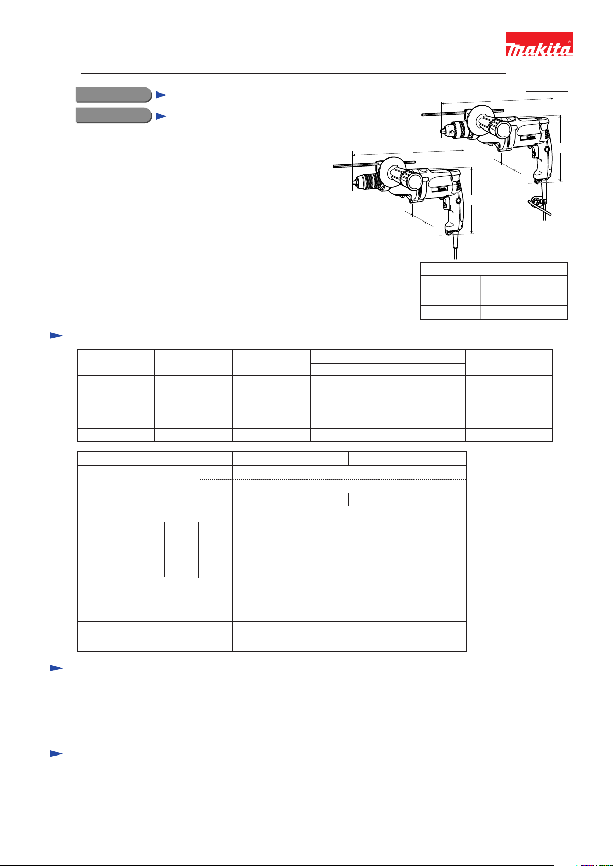
L
W
DP4011
Length (L) 347 (13-5/8)
Width (W)
Height (H)
Continuous Rating (W)
Input Output
720
---
720
720
720
360
360
360
360
360
H
W
DP4010
H
Dimensions: mm (")
70 (2-3/4)
220 (8-5/8)
Max. Output (W)
660
660
660
660
660
Model
No load speed: min -1= rpm
Drill chuck type
Chuck capacity: mm (")
Steel
Capacities: mm (")
Wood
Reverse switch
Torque limiter Yes
Protection against electric shock
Power supply cord: m (ft)
Net weight: kg (lbs)
High
Low
High
Low
High
Low
DP4010
0 - 2,900
0 - 1,200
Keyed
1.5 - 13 (1/16 - 1/2)
8 (5/16)
13 (1/2)
25 (1)
40 (1-9/16)
Yes
Double insulation
2.5 (8.2)
2.2 (4.9)
Standard equipment
Chuck key S-13 ............... 1 (for DP4010)
Key holder 12 .................. 1 (for DP4010)
Side handle ...................... 1
Depth gauge ..................... 1
Note: The standard equipment for the tool shown above may differ by country.
DP4011
Keyless
Optional accessories
Metal drill bits 1.5 - 13 mm (1/16 - 1/2")
Wood drill bits 3 - 40 mm (1/8 - 1-9/16")
Center drill for hole saw
Hole saws 16 - 90 mm (5/8 - 3-1/2")
Metal borers 14 - 35 mm (9/16 - 1-3/8")
Depth gauge
Wrench 9
Side handle
Drill chuck
Chuck key S-13 (for DP4010)
Drill stand Type 43
Page 2
P 2 / 8
Repair
CAUTION: Remove the bit from the machine for safety before repair/ maintenance
in accordance with the instruction manual!
[1] NECESSARY REPAIRING TOOLS
DescriptionCode No. Use for
781024-2 Wrench 43
Gear extractor (large)1R045
1R139 Drill chuck extractor
1R223 Torque wrench shaft 20-90N.m
1R224 Ratchet head 12.7 for 1R223
1R298
1R316
Hex. bar 10 with square socket
Bearing extractor1R269
Wrench for bearing retainer
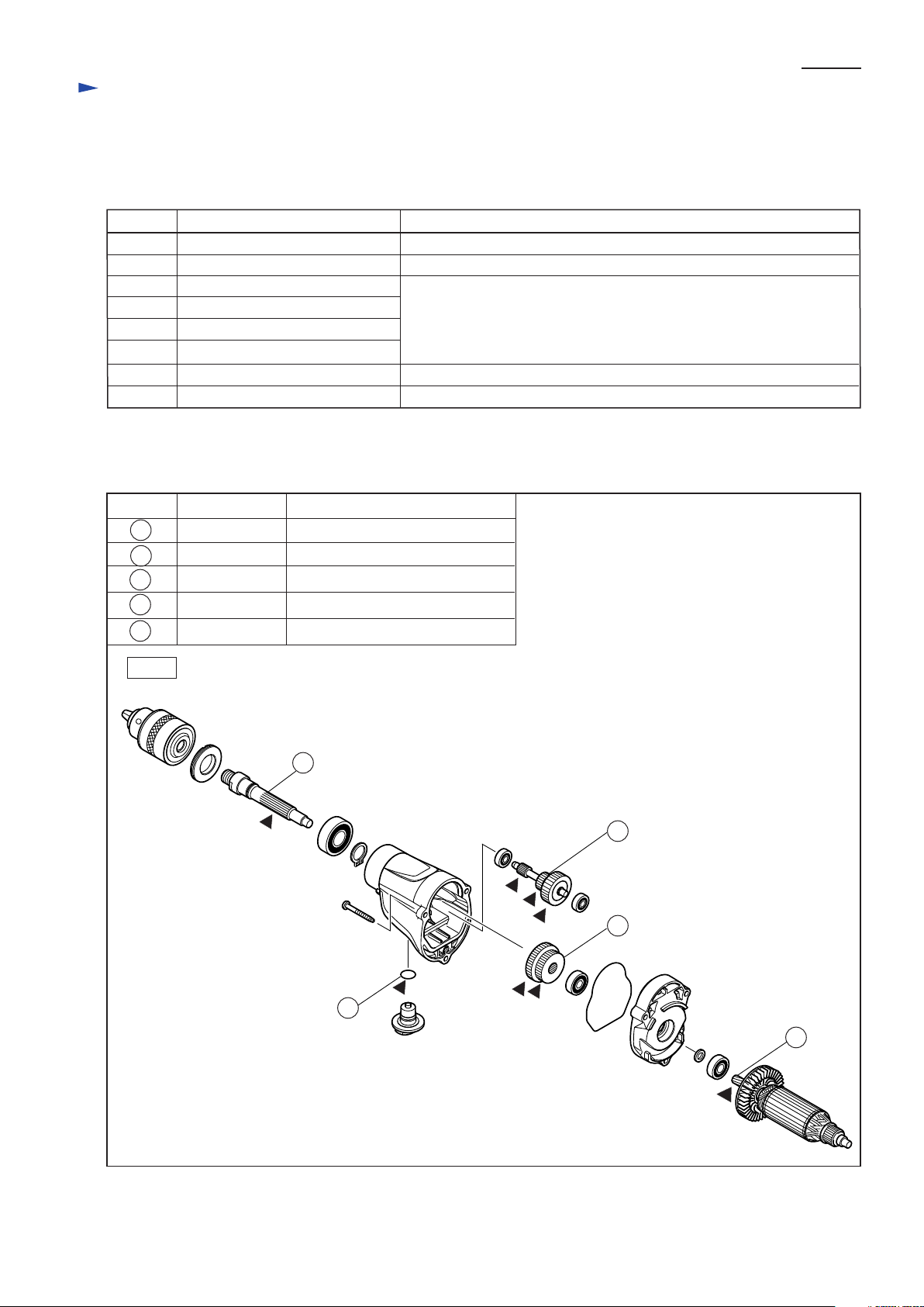
[2] LUBRICATION
Apply 30g in total of Makita grease N. No.1 to the following portions designated with the black triangle to protect parts
and product from unusual abrasion.
Item No. Description Portion to lubricate
3
13
15
30
19
Spindle
Gear complete Gear teeth
Spur gear 29-37 Gear teeth
Armature Gear teeth
O ring 12 Whole portion
Spline portion
Removing the damaged Keyed-drill chuck
Removing Armature
Removing / Assembling Drill chuck
Removing Ball bearings
Removing / Assembling Bearing retainer
Fig. 1
3
13
15
19
30
Page 3
P 3 / 8
Repair
[3] DISASSEMBLY/ASSEMBLY
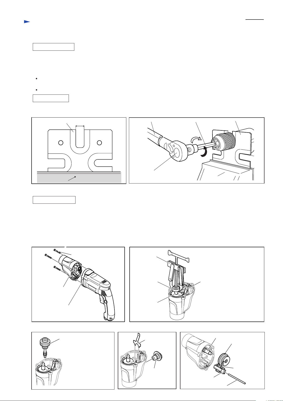
[3] -1. Drill Chuck
DISASSEMBLING
1) Secure 1R139 firmly with Vise as illustrated in Fig. 2.
2) Fix Spindle on 1R139 by inserting Spindle into the U-shaped notch on 1R139 with the flat sides of the Spindle
facing the edges of the notch. And then remove Drill chuck by turning it counterclockwise with 1R223, 1R224 and
1R298. (Fig. 3)
Use Pipe wrench to remove the Drill chuck, if the sleeve of Drill chuck does not turn because of some troubles
with Drill chuck. Grip the periphery of the sleeve with wrench, and turn wrench counterclockwise.
The keyed Drill chuck of DP4010 can be removed using a Wrench 43 (781024-2).
ASSEMBLING
When fastening the Drill chuck to the Spindle, set the torque of 1R223 to 35.7 to 45.9 N.m.
Fig. 2
8419B
1R139
UT2201
6310
DP4700
17.0mm (11/16")
HP2031
8420V
8406C
8406
6300L
6300LR
6013BR
6300-4
Fig. 3
1R223
1R298
Fastening
1R139
Loosening
1R224
Vise
Vise
[3] -2. Gear Section
DISASSEMBLING
1) Remove three 4x35 Tapping screws, and Separate Gear housing from Gear housing cover complete. (Fig. 4)
2) Remove Ball bearing 608ZZ from Spindle with 1R269 (Fig. 5) and pull out Gear complete with Ball bearing 606ZZ.
(Fig. 6)
Note: Gear complete with Ball bearing 606ZZ can not be pulled out without removing Ball bearing 608ZZ in advance.
3) After removing Lock plate, pull off Change lever B. (Fig. 7)
4) Remove Spur gear 29-37 from Spindle. Change plate B, Rack 12 and Pin 4 can be removed. (Fig. 8).
Fig. 4
4x35 Tapping screw: 3 pcs.
Gear housing
Gear housing cover complete
Fig. 5
1R269
Ball bearing
608ZZ
Spindle
Gear complete with Ball
bearing 606ZZ
(A part of Gear complete is
caught on Ball bearing 608ZZ.)
Fig. 6 Fig. 7
Gear complete with
Ball bearing 606ZZ
Note: Do not disassemble
the Gear complete,
because it has torque
limiter function and
requires difficult
adjustment when
reassembled.
Lock plate
Change lever B
Fig. 8
Spindle
Spur gear 29-37
Change plate B
Rack 12
Pin 4
Page 4

P 4 / 8
Repair
[3] DISASSEMBLY/ASSEMBLY
[3] -2. Gear Section (Cont.)
ASSEMBLING
1) Insert the arms of Change plate B through the slots in Rack 12, and then put Spur gear 29-37 between the arms of
Change plate B. (Fig. 9)
2) Insert the Pin 4 into Rack 12. Install Spur gear 29-37 to Spindle together with the parts you have assembled toRack 12.
(Fig. 10)
At this time, do not fail to set Leaf spring in place. (Fig. 10)
Fig. 9
Spur gear 29-37
Rack 12
arm
Change plate B
3) Push Rack 12 into Gear housing until it stops.
And then, install Change lever B on Gear housing
with its "I" mark which indicates low speed aligned
with the triangular mark on Gear housing. (Fig. 11)
4) Install Lock plate on Gear housing with its tail portion
inserted between the ribs on Gear housing as
illustrated in Fig. 11.
5) Assemble Gear complete with Ball bearing 606ZZ
to Gear housing as illustrated in Fig. 6.
Fig. 10
Gear housing
Fig. 11
Spur gear 29-37
Spindle
Leaf spring
Spur gear 29-37
Pin 4
Rack 12
with change plate B
Spindle
Rack 12
Change lever B
Align with I.
Ribs
Lock plate
Page 5

P 5 / 8
Repair
[3] DISASSEMBLY/ASSEMBLY
[3] -3. Armature
DISASSEMBLY
1) Disassemble Handle cover by removing Tapping screws. Then remove Carbon brush with slotted screwdriver (Fig. 12)
2) Remove Gear housing cover complete from Motor housing after removing Gear housing. (Fig. 4)
Therefore, Armature comes out with Gear housing cover complete.
3) Remove Armature from Gear housing cover complete with 1R045. (Fig. 13)
4) The Ball bearings are removed from the both end of Armature shaft. (Figs. 14 and 15)
Fig. 12
Handle cover
Slotted
screwdriver
M4x25 Tapping screw
Carbon brush
Carbon brush
Fig. 13
Fig. 15
After removing Labyrinth rubber ring 19, Ball bearing 607LLB and Insulation washer are removed.
Labyrinth rubber ring 19
Armature
1R045
Gear housing
cover complete
Fig. 14
1R269
Note: When replacing Ball bearing 608DDW,
it is removed together with Ring 8.
This Ring 8 is easy to be deformed.
Therefore, do not reuse Ring 8
when removing it.
Ring 8
Ball bearing
608DDW
Ball bearing 607LLB Insulation washer
ASSEMBLY
Do the reverse of the disassemble step.
1R269
Page 6

Repair
[3] DISASSEMBLY/ASSEMBLY
[3] -4. Bearing Retainer 19-36
DISASSEMBLY
(1) Remove Gear section from Gear housing. Refer to Figs. 4 to 8.
(2) Remove Bearing retainer 19-36 with 1R316. (Fig. 16)
(3) Ball bearing 6202LLB can be disassembled as illustrated in Fig. 17.
Fig. 16
1R316
P 6 / 8
Bearing retainer 19-36
Fit these pins of 1R316
to the groove of
Bearing retainer 19-36.
Fig. 17
Retaining ring S-15
Ball bearing 6202LLB
Spindle
Turn 1R316 clockwise,
and Bearing retainer 19-36
will be removed.
Retaining
ring S-15
ASSEMBLY
Do the reverse of the disassembling step.
Ball bearing 6202LLB
Page 7

Circuit diagram
Fig. D-1
P 7 / 8
Color index of lead wires' sheath
Black
White
Red
Purple
Blue
FA F'A
Brush
Holder A
FB
Brush
Holder B
F'B
Switch
Noise
suppressor
Power supply cord
Page 8

Wiring diagram
Fig. D-2
P 8 / 8
Fix the Lead wires with
Lead wire holder.
FA F'A
Fix the Lead wires with
Lead wire holder.
Brush
Holder A
FB F'B
Switch
Brush
Holder B
Route the Lead wires of
Power supply cord between
the inner wall and the Rib.
Noise suppressor
Noise Suppressor is not
used for some countries.
Power supply cord
 Loading...